1
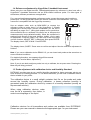
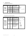
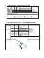
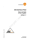
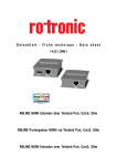
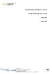
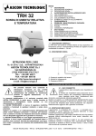
Calibration Procedure for ROTRONIC
Digital Products
and Service Cable Overview
Contents:
1.
Procedures: ..............................................................................................................2
1.1
General recommendations ................................................................................2
1.2
Sources of errors...............................................................................................2
1.3
Periodic probe calibration..................................................................................2
1.4
Reference adjustment by HygroPalm 3 handheld instrument ...........................3
1.5
Probe adjustment with calibration device and Humidity Standard .....................3
2. Cable Overview ........................................................................................................5
2.1
HygroPalm connected to PC .............................................................................5
2.2
HygroPalm connected to HygroFlex..................................................................5
2.3
HygroPalm connected to M- & Roline L Series .................................................6
2.4
M23 / M33 connected directly to PC..................................................................6
2.5
M1-Series & Roline L connected to PC via HygroPalm.....................................7
2.6
M1- & Roline L Series connected to PC via MOK-WIN and ACRLXB5 .............7
2.7
M1S- & Roline LxS Series connected to PC via MOK-WIN and ACRLXB5 ......8
2.8
Frequently asked questions ..............................................................................9
3. Theory on calibration ..............................................................................................10
3.1 Multipoint adjustment ...........................................................................................10
3.2
Single point Adjustment...................................................................................13
1.
Procedures:
1.1 General recommendations
Relative humidity is extremely dependent on temperature. Proper measurement of relative
humidity requires that the probe and its sensors are at exactly the temperature of the
environment to be measured. Because of this, the location you choose to install the probe can
have a significant effect on the performance of the instrument. The following guidelines should
guarantee good instrument performance:
a) Select a representative location: install the probe where humidity, temperature and pressure
conditions are equal to the environment to be measured.
b) Provide good air movement at the probe: air velocity of at least 1 meter/second
facilitates adaptation of the probe to changing temperature.
c) Avoid the following:
Close proximity of the probe to a heating element, a cooling coil, a cold or hot wall, direct
exposure to sun rays, etc.
Close proximity of the probe to a steam injector, humidifier, direct exposure to precipitation
etc., unstable pressure conditions resulting from excessive air turbulence.
1.2 Sources of errors
Measurement values may be affected by :
- Temperature faults:
Too short adaptation time, cold walls, heating elements, sun radiation etc. Even the
body-radiation of man may affect the measurement. When calibrating, keep as much
distance as possible.
- Humidity faults
Humidity errors due to sprayed steam or water, dripping water, attempts to measure nonhygroscopic substances. The reproducibility and long-term stability are not influenced even if
the sensor was exposed to high humidity or saturation with water vapour condensation.
1.3 Periodic probe calibration
The Pt 100 RTD temperature sensor as well as the electronics are very stable and normally do
not have to be adjusted after the factory-calibration.
The long-term stability of the ROTRONIC Hygromer sensors is typically better than
1 %rh per year. For maximum accuracy, we recommend to calibrate the probes once or twice a
year. In applications where the sensor is exposed to pollutants, it may be necessary to calibrate
or adjust more often. The calibration may be performed by the user on-site or in the
laboratory/workshop.
For routine calibrations, the probe should be checked at one point, preferably at the
prevailing values. For applications in the ambient, this would normally be at 50 %rh.
In industrial and pharmaceutical applications, where the accuracy must be higher, we
recommend to calibrate the probes at 3 points: (in this sequence): 35, 80, 10 %rh.
If measurements are performed at very low humidity, we recommend to calibrate/ adjust
also at 0 (0.5) %rh.
Note: The electronics of the Rotronic transmitters usually does not require any field
maintenance. However, the probe itself should be calibrated at least once per year, in order to
maintain it’s high quality. For details of calibration, see users manual (full version). It may be
downloaded from the internet.
\\Kalibrierung\Calibration_procedures_2.doc
2
1.4 Reference adjustment by HygroPalm 3 handheld instrument
When using the new digital devices, calibration/adjustment by reference is done best with a
HygroPalm 3 handheld instrument and an SCS-certified reference probe. For older types of
transmitters, different procedures are applicable.
For a one point adjustment against a reference probe, connect the proper service cable to
probe input 1 of the HygroPalm3 and to the service connector of the transmitter. (The 5-pin
connector is compatible with the HygroClip connector).
Use an adaptor cable such as MOK-02-B5 to connect the
reference probe to probe input 2 of the HygroPalm 3. (Details
regarding the service cable / device combination you will see in
the tables on pages 5 to 7.) Bring both probes next to each other.
Allow sufficient time to acclimate. Be careful not to influence the
measurement by body-radiation/humidity. When the equilibrium is
reached (both arrows of the trend indicator visible), you’re ready
for adjustment. Press the „Menu“ key, then one of the arrow keys
until the function „ADJUST REF“ is displayed. Now press ENTER.
The display shows „REF=PALM“. Press ENTER.
The display shows „SURE?“ Press enter to confirm and adjust. Now the reference adjustment is
finished.
Note: If you use a calibration device EDM15-15, you can insert both probes at the same time to
ensure identical conditions.
For detailed information, see separate HygroPalm manual.
(HygroPalm Function Menu, Adjust Ref.)
Note: If you do not wish to adjust a probe, but only to calibrate, do not press enter. Pressing the
Menu key will bring you back.
1.5 Probe adjustment with calibration device and Humidity Standard
ROTRONIC provides easy-to-use, certified humidity standards for those customers who do not
have access to a humidity generator. To use these standards, you will need a calibration device
that is suitable for your probe.
The calibration device is a small airtight container that fits on the probe and seals
around the humidity sensor. During calibration, a known reference humidity is
generated inside the calibration device by means of a humidity standard (usually an
aqueous salt solution).
When using calibration devices, make
sure the lid is screwed-in from below, in
order to avoid spillage of the liquid.
Calibration devices for all transmitters and probes are available from ROTRONIC.
Please see your user manual to determine the appropriate type for your instrument.
\\Kalibrierung\Calibration_procedures_2.doc
3
Certified Humidity Standards
The ROTRONIC certified standards are available in boxes of 5 glass ampoules of the same
value, which can be stored indefinitely. Standards in the range of 5 to 95 %RH are nonsaturated aqueous salt solutions that are precisely titrated at our factory for the right
concentration. The 0 %RH humidity standard is made of small granules of a highly porous
ceramic that have been dried at a high temperature. A Material Safety Data Sheet is available
for each standard. Since most standards are a salt solution, parts which have come in contact
with the liquid should be cleaned after each use.
Each box of standards comes with a certificate that provides statistical information on the
manufacturing batch of the standard. Information on the effect of temperature on each standard
is provided on the cover of each box of standard. When calibrating either with the HygroPalm or
with the HW3 software, the effect of temperature on the standards is compensated by the
software and no further correction is required. The value of the standards is not affected by
altitude.
Instructions for using the Standards
• Install the calibration device on the probe so that the receptacle (or solution holder) is under
the probe. Check for a tight fit and remove the receptacle from the calibration device.
• Place one fibre disc (each box of standards includes 5 discs) in the receptacle of the
calibration device. The purpose of this disc is to prevent accidental spilling of the solution
inside the calibration device or on the humidity sensor.
• Tap the top of the ampoule so that all liquid drops to the bottom of the ampoule. Snap off top
and empty contents on fibre disc. Since the ampoule is made of glass, exercise proper
caution (gloves, safety glasses) when snapping off the top.
• Put the receptacle back on the calibration device and make sure that the solution does not
come in contact with the sensor: The solution inside the calibration device should never be
on top of the sensors.
• Allow at least 60 minutes to insure that the calibration device, the solution and the sensor
are in a state of equilibrium. This is verified by monitoring the display.
• After adjusting the probe, remove the receptacle from the calibration device. Throw away the
wet disc (non reusable). Thoroughly wash and wipe dry the receptacle.
General Recommendations
During calibration, temperature stability is the single most important requirement. If possible,
calibrate the probe at room temperature (18 to 25°C). Room temperature should be stable to ±
0.25°C or better during the period of time required for each calibration point. Do not calibrate
close to an air vent or a heater, in direct exposure to sun rays, etc.
If using a humidity generator to calibrate the probe, make sure that the probe is as fully
immersed in the generator as possible to minimize temperature effects.
\\Kalibrierung\Calibration_procedures_2.doc
4
2.
Cable Overview
2.1 HygroPalm connected to PC
Service Cable
RS232
Cable
AC1622
Palm 2 Palm 3 Possible Functions
yes
yes
yes
yes
yes
yes
yes
yes
B3<>D9sub
Communication by RS232
between Palm and PC,
Configuration of Palm with
HW3
1 point probe adjustment of
probe 1, probe 2 or both at the
same time
Multi point probe adjustment of
probe 1, probe 2 or both at the
same time
1 point adjustment against
reference probe
In this function, probe 2 is
always the reference probe
2.2 HygroPalm connected to HygroFlex
Service Cable
Palm 2
Palm 3
yes
yes
yes
yes
yes
yes
yes
yes
Remote
Cables
AC1621
DAT5<>B2
AC1620
B5<>B2
\\Kalibrierung\Calibration_procedures_2.doc
Possible Functions
Display the readings from
any probe connected to the
HygroFlex
Display the HygroFlex
status (configuration, serial
number, etc.)
1-point adjustment of any
HygroClip digital probe
connected to the
transmitter, using the probe
connected to the
HygroPalm as a reference
Access the functions
(except for calculate and
display) of the transmitter,
primarily the adjust M.PT
function for multi point
probe calibration
5
2.3 HygroPalm connected to M- & Roline-L Series
Service
Cable
ACRLXB5
B5<>HE14-10
ACRLYB5
M1
M22
M23/M33
L-1x
yes
yes
yes
yes
no
no
yes
no
yes
yes
yes
yes
yes
yes
yes
yes
yes
yes
yes
yes
no
no
yes
no
Yes
no
no
yes
Possible Functions
Display the measurement values of
any probe connected to the M2 / M3
transmitter
Display the status (configuration, serial
number, RS status, probe serial
number, firmware version etc.)
1-point adjustment of any digital probe
respectively transmitter, using the
probe connected to the HygroPalm
probe 2 connector as a reference
1-point adjustment of any digital probe
respectively transmitter, using a RHS
humidity standard.
Multi- point adjustment of any digital
probe respectively transmitter, using a
RHS humidity standard.
Set trend indicator and units of the
transmitter
Probe adjustment and output validation
Works only in conjunction with
ACRL001…ACRL420
2.4 M23 / M33 connected directly to PC
Device
Service cable
ACML232
M23
M33
Yes
Yes
Yes
Yes
Possible
Functions
Configuration of transmitter
Scaling of output signals
1-point adjustment
Multi point adjustment
\\Kalibrierung\Calibration_procedures_2.doc
6
Accessories
required
PC, HW3 software
2.5
M1-Series & Roline-L connected to PC via HygroPalm
Device
Service cable
ACRL001
ACRL005
ACRL010
ACRL020
ACRL420
M1xW
M1S
M1xD
Yes
Yes
Yes
Yes
L1x
Yes
Yes
Possible
Functions
Scaling of output signals
Adjustment of digital/analog
converter
Service cable compensation
Simulation of analogue outputs
Accessories
required
PC, HW3
software,
HygroPalm,
AC1622 or
Docking Station
Yes
Yes Yes
Yes
Yes Yes
Note:
Use the appropriate cable according to the output signal of the transmitter that
is to be adjusted
2.6 M1- & Roline-L Series connected to PC via MOK-WIN and ACRLXB5
Device
M1xW
M1xD
L1xD/W
Yes
Yes
Yes
Yes
Yes
Yes
Yes
Yes
Yes
Yes
Service cable
MOK-02-WIN
Possible
Functions
Display the measurement
values of the M1 / L1x
transmitter
1-point adjustment using a
RHS humidity standard.
Multi- point adjustment using
a RHS humidity standard.
1 point or 2 point adjustment
of temperature
Display the serial number, last
calibration date of
temperature and humidity
calibration)
Accessories required
PC running
HW3 software
ACRLXB5
MOK-02-WIN
(eventually
AC adaptor AC1207)
Note:
HW3 will recognize the transmitters as a single HygroClip probe.
Do not attempt to adjust temperature unless you have very accurate reference
instruments!
\\Kalibrierung\Calibration_procedures_2.doc
7
2.7 M1S- & Roline-LxS Series connected to PC via MOK-WIN and ACRLXB5
Device
M1xS
M1xS
L1xS
Yes
Yes
Yes
Yes
Yes
Yes
Yes
Yes
Yes
Yes
Service cable
MOK-02-WIN
Possible
Functions
Display the measurement
values of the M1 / L1x
transmitter
1-point adjustment using a
RHS humidity standard.
Multi- point adjustment using
a RHS humidity standard.
1 point or 2 point adjustment
of temperature
Display the serial number, last
calibration date of
temperature and humidity
calibration)
Accessories required
PC running
HW3 software
AC1625
MOK-02-WIN
(eventually
AC adaptor AC1207)
Note:
HW3 will recognize the transmitters as a single HygroClip probe.
Do not attempt to adjust temperature unless you have very accurate reference
instruments!
Note:
The shaded functions can be performed with the distributor version of HW3 only.
\\Kalibrierung\Calibration_procedures_2.doc
8
2.8 Frequently asked questions
Question:
I am using at present a ACRL010 on a HygroPalm 3, input 1. I plug into the M-series. Input 2 is
connected to a MOK-02-B5 with my reference HygroClip. I read the unit and compare the value with the
value of the HygroClip on input 2. I go then to adjust the M22 series. I go to adjust REF. Palm displays
“Palm = Reference” and I press OK, and I adjust my M-series. Is this OK or do I risk errors on the ACRL
010 ? The input 1 of the HygroPalm is configured for a digital probe.
Answer:
The HygroClip probes connected on any of the M-series transmitters can be adjusted that way. It
must be pointed out, that only the HygroClip probes, but not the output signals can be adjusted
that way. Of course, the output signal will be changed also according to the adjustment deviation
of the probe.
Question:
When I do a multi point adjust, I do e.g. 35 % as first point and I come out of the menu and change my
solution to e.g. 80 %. I then await stabilization and go back into the adjust menu and do my 80 %. How
does the clip know that its not a 1 point adjust at 80 % instead of a second point at 80 %? The fact that I
began at 35 % does it memorize or does this set something off ?
Answer:
The determination is done in the adjustment window of HW3. There you select either a single or
multi-point adjustment.
If a multipoint adjustment is done, the software will check for the entered values.If a value
between 25 and 55 %rh is entered, the algorithm will consider this as the offset point. A value >55
% is considered as slope value, while a value >1>25 % is used for linearity adjustment in the low
range.
Question:
When I do a 1 point adjustment, is the adjusted probe only correct for the point done and false for the rest
of the curve.? When I do one point do I not just displace the whole slope up or down?
Answer:
A one point adjustment always just influences the offset, but not the slope and neither the
linearity. This means that on the particular point, the instrument will be accurate, but the farther
away from that point, the bigger the deviation. Within HW3 and also with HygroPalm handhelds,
you can always select the mode of adjustment: 1 point or multiple point. When you select one
point, you definitely move the offset and only the offset.
The offset is the parallel movement of the whole curve in vertical direction as shown in the left
graph, while the slope is the steepness of the curve, as the graph to the right shows.
Offset
Slope
A fourth point may be adjusted in order to get perfect linearity.
Details see in subsequent pages.
\\Kalibrierung\Calibration_procedures_2.doc
9
3.
Theory on calibration
3.1 Multipoint adjustment
An ideal characteristic line of a sensor would be absolutely straight.
Output
67
[F]
67
A real characteristic line of a humidity sensor curve is not straight, but slightly
bent. Hence, the aim must be to achieve a linearisation.
Output
Relative humidity
0
10
80
35
Adjustment points
The Hygromer® sensor is by its nature linear between 30 and 100 %rh.
Below 30 %rh, there is a kink in the curve which needs linearisation.
Therefore, the adjustment point are set as follows:
1st point (Offset) 35 %rh
2nd point (Slope) 80 %rh
3rd point (Linearity between 30 and 10 %rh
4th point (Linearity between 10 and 0 %rh
\\Kalibrierung\Calibration_procedures_2.doc
10
As first step to achieve this, the offset value must be set correctly.
This is usually done at 35 %rh.
Output
Ideal curve
Before adjustment
After adjustment
Relative humidity
(0)
(10)
35
80
Adjustment points
The offset is now adjusted, the blue line goes through the 35 % point. As the line is not
going trough zero and maximum, the slope and linearity must be adjusted next: The
slope will be set at 80 %. This results in linearity between 30 and 100 %.
Output
e.g. 80%
Pivot at 35%
Relative humidity
(0)
(10)
\\Kalibrierung\Calibration_procedures_2.doc
35
80
11
Adjustment points
Next, the linearity between 30 and 10 % must be set:
Output
Fix due to 80% adjustment
Fix due to 35% adjustment
Relative humidity
(0)
35
10
80
Adjustment points
If measurement is required below 10%rh, the 4th point should also be set. Usually, this is
done at 0 (0.5 %rh
Output
e.g 80%
e.g.35%
10%
0%
Relative humidity
0
10
80
35
Adjustment points
When all these adjustments are done, the characteristic line is linear, and the probe is
perfectly adjusted.
\\Kalibrierung\Calibration_procedures_2.doc
12
3.2 Single point Adjustment
If a one point adjustment only is performed, the measured values are accurate around
the selected point. But as slope and linearity are not adjusted, the ranges that are far
away from the adjusted point are not very accurate.
Offset of the
charachteristic
Output
Relative humidity
0
10
35
80
Adjustment points
We therefore recommend to perform multiple-point adjustments in order to achieve
maximum accuracy.
\\Kalibrierung\Calibration_procedures_2.doc
13