1
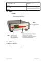
E-M-HyLabC1-V1 Rotronic AG Bassersdorf, Switzerland Document code Unit HygroLab C1 bench-top indicator: User Guide Instruction Manual Document Type Page Document title 1 of 28 HygroLab C1 Bench-Top Indicator User Guide © 2011; Rotronic AG E-M-HyLabC1-V1 E-M-HyLabC1-V1 Rotronic AG Bassersdorf, Switzerland Document code Unit HygroLab C1 bench-top indicator: User Guide Document title Instruction Manual Document Type Page 2 of 28 Table of contents 1 Overview ...................................................................................................................................................... 3 2 General description .................................................................................................................................... 4 2.1 Configuration software ............................................................................................................................. 4 2.2 Power supply............................................................................................................................................ 4 2.3 Probe inputs ............................................................................................................................................. 4 2.4 Measured parameters .............................................................................................................................. 4 2.5 Calculated parameters ............................................................................................................................. 4 2.6 Alarm Indication on the display ................................................................................................................ 5 2.7 Real time clock ......................................................................................................................................... 5 2.8 Back panel and digital interface ............................................................................................................... 5 3 Basic operation ........................................................................................................................................... 6 3.1 Display ..................................................................................................................................................... 6 3.2 Keypad ..................................................................................................................................................... 7 3.3 ON/OFF key ............................................................................................................................................. 7 3.4 Internal menu ........................................................................................................................................... 8 3.5 Frequently used settings ........................................................................................................................ 11 3.5.1 Unit system ............................................................................................................................ 11 3.5.2 Date and time ......................................................................................................................... 11 3.5.3 Select the calculated parameter for a probe input .................................................................. 11 3.5.4 Select which probe and/or parameters are shown on the display .......................................... 11 3.6 Connecting the HygroLab C1 to a PC .................................................................................................... 11 3.7 Practical advice for measuring humidity ................................................................................................. 12 4 Aw Measurement ...................................................................................................................................... 12 4.1 Enabling Aw Measurement .................................................................................................................... 12 4.2 Water activity measurement settings:..................................................................................................... 13 4.3 Aw probe usage guidelines .................................................................................................................... 13 4.4 Using the AwQuick mode ....................................................................................................................... 14 4.5 Using the AwE mode .............................................................................................................................. 17 4.6 Viewing the captured data (automatic data capture enabled) ................................................................ 19 5 User configurable settings and functions .............................................................................................. 20 5.1 Factory default settings .......................................................................................................................... 20 5.2 Interaction between the HygroLab C1 and HygroClip 2 probe ............................................................... 21 5.3 User defined parameter.......................................................................................................................... 21 6 Maintenance .............................................................................................................................................. 22 6.1 Periodic calibration check of the HygroClip 2 probe ............................................................................... 22 6.2 Cleaning or replacing the probe dust filter .............................................................................................. 22 6.3 Firmware updates................................................................................................................................... 22 7 Probe Calibration and Adjustment Procedures ..................................................................................... 23 7.1 Overview ................................................................................................................................................ 23 7.2 Calibration against a reference environment .......................................................................................... 23 7.3 Calibration against a reference HygroClip 2 probe................................................................................. 24 7.4 Adjustment of humidity and temperature ................................................................................................ 24 8 Technical data ........................................................................................................................................... 25 8.1 Specifications ......................................................................................................................................... 25 8.2 Dew point accuracy ................................................................................................................................ 26 9 Accessories............................................................................................................................................... 27 10 Supporting documents............................................................................................................................. 27 11 Document releases ................................................................................................................................... 28 © 2011; Rotronic AG E-M-HyLabC1-V1 E-M-HyLabC1-V1 Rotronic AG Bassersdorf, Switzerland Document code Unit HygroLab C1 bench-top indicator: User Guide Document title Instruction Manual Document Type Page 3 of 28 Applicability: This manual is valid for the HygroLab C1 with firmware version 1.xx, where 1.xx can be 1.0a, 1.1b etc. Changes to the last two digits of the version number reflect minor firmware changes that do not affect the manner in which the instrument should be operated. 1 Overview The HygroLab C1 is a multifunction bench-top indicator that can read simultaneously up to 4 HygroClip 2 digital humidity-temperature probes. The HygroLab C1 is primarily designed for measuring the water activity (aw) of foods, pharmaceuticals and cosmetics. The HygroLab C1 can also be used in other laboratory applications that require measuring humidity and temperature. The HygroLab C1 is equipped with both a USB and an Ethernet interface. The HygroLab C1 features two distinct operating modes: ► Aw Measurement: This specialized mode is used for measuring the water activity (Aw) of product samples and materials in bulk such as powders, seeds, etc. When set to operate in the water activity mode, the HygroLab C1 automatically displays humidity as Aw (1.000 aw = 100 %RH). The Aw Mode offers the following options: Accelerated water activity measurement (AwQuick): permits measuring the water activity of most products in typically 5 minutes. The measurement starts simultaneously for all four probe inputs and is ended automatically. Conventional water activity measurement (AwE): the measurement starts simultaneously for all four probe inputs. The HygroLab C1 automatically detects full equilibrium conditions and ends the measurement at that time. The HygroLab automatically signals the end of each water activity measurement and offers the option of automatically capturing both the end result and the value of temperature in 4 separate data bins (one nonvolatile memory per probe). Up to 500 records can be captured per probe and each record is stamped for date and time. Data viewing can be done from the keypad and the data can be saved to a PC using the Rotronic HW4 software. ► Standard Mode: in this mode the HygroLab C1 can be used as a general purpose indicator with the following functions: o Relative humidity and temperature data measured by up to 4 HygroClip 2 digital probes o Calculated humidity parameter such as dew / frost point or other, for up to 4 HygroClip 2 probes o Up to 4 user defined calculations such as the difference between the temperature and the dew point measured by a probe, the average of the temperature measured by two probes, etc. The HygroLab C1 is available with a wide assortment of HygroClip 2 humidity-temperature probes to meet almost any requirement. The HygroClip 2 probes feature well proven, durable sensors. Digital signal processing ensures consistent product performance and also facilitates the task of field maintenance with features such as potentiometer free – digital calibration. © 2011; Rotronic AG E-M-HyLabC1-V1 E-M-HyLabC1-V1 Rotronic AG Bassersdorf, Switzerland Document code Unit HygroLab C1 bench-top indicator: User Guide Instruction Manual Document Type Page Document title 2 General description 2.1 Configuration software 4 of 28 Most of the HygroLab C1 settings can be configured directly from the keypad. However, some of the settings and access to some of the functions requires connecting the HygroLab C1 to a PC running the HW4 software version 3.1 or higher, using either USB or Ethernet. For instructions see the following HW4 manual: E-MHW4v3-F2-019 2.2 Power supply The HygroLab C1 requires the power adapter model AC1211 (100…240 VAC – 12 VDC, 200 mA). As an alternative, the HygroLab C1 can also be powered via the USB port (no power adapter - current draw: about 70 mA). In this case, the Ethernet port is inactive and cannot be used. 2.3 Probe inputs The HygroLab C1 has 4 probe inputs designed for use with all HygroClip 2 digital probes with the standard UART interface (see also Back panel and digital interface options). Pin-Out Diagram 1: RXD (UART- digital probe) 2: GND (digital and power) 3: V+: 3.3 VDC nominal 4: Not used 5: Not used 6: Not used 7: TXD (UART – digital probe) 2.4 Measured parameters The HygroClip 2 probe measures relative humidity with a ROTRONIC Hygromer® IN1 capacitive sensor and temperature with a Pt100 RTD. 2.5 Calculated parameters The HygroLab C1 can calculate any of the following parameters based on the humidity and temperature values measured by the probe (to select the calculated parameter, use either the keypad or the HW4 software > Device Manager): o o o o o o o o o o Dew point (Dp) above and below freezing Frost point (Fp) below freezing and dew point above freezing Wet bulb temperature (Tw) Enthalpy (H) Vapor concentration (Dv) Specific humidity (Q) Mixing ratio by weight (R) Vapor concentration at saturation (Dvs) Vapor partial pressure (E) Vapor saturation pressure (Ew) © 2011; Rotronic AG E-M-HyLabC1-V1 E-M-HyLabC1-V1 Rotronic AG Bassersdorf, Switzerland Document code Unit HygroLab C1 bench-top indicator: User Guide Document title Instruction Manual Document Type Page 5 of 28 Note: calculating some of the above parameters requires barometric pressure as an input parameter. A fixed barometric pressure value can be specified using either the keypad or the ROTRONIC HW4 software. In addition, the HygroLab C1 can display for each probe input a user defined calculation such as the difference between the temperature and the dew point measured by a probe, the average of the temperature measured by two probes, etc. Configuration of the HygroLab C1 for a user defined calculation requires the Rotronic HW4 software version 3.1 or higher (see separate document E-M-HW4v3-F2-019) 2.6 Alarm Indication on the display Depending on the type of alarm, the display shows either a symbol or a text when the HygroLab C1 detects an alarm condition: o o o 2.7 Out-of-limits value (defined with the HW4 software for each probe input, includes measured values and calculated parameter). Display of fixed values when no probe is connected the input. Easily identified humidity and temperature values can be specified with the HW4 software for each probe input. Bad RH sensor or major sensor failure (open or shorted sensor – humidity and temperature) Real time clock The HygroLab C1 clock keeps track of the date and time and can be adjusted from the keypad. Using the HW4 software, the clock can be synchronized with the PC date and time. The clock does not automatically adjust for daylight saving time (DST). 2.8 Back panel and digital interface As an option, the HygroLab C1 is available with any of the following digital interfaces: o o o USB only (can be used to power the HygroLab C1) Ethernet only (RJ45) USB and Ethernet (only one interface can be used at any time) Use of the Ethernet interface always requires the HygroLab to be powered with the AC1211 power adapter. HygroLab C1 back panel showing the four probe inputs as well as the USB and Ethernet ports: © 2011; Rotronic AG E-M-HyLabC1-V1 E-M-HyLabC1-V1 Rotronic AG Bassersdorf, Switzerland Document code Unit HygroLab C1 bench-top indicator: User Guide Instruction Manual Document Type 6 of 28 Page Document title 3 Basic operation 3.1 Display The LC display has a backlight which can be set to be on all the time or whenever a key is pressed. The backlight can also be disabled. Using the HygroLab C1 Menu > Display Settings > Mode, the display mode can be changed as shown below: Standard: o o o %RH Temperature Date and time 3-line display: o o o o %RH Temperature Calculated parameter No date and time The display can also be configured to show a trend indicator on each line: ▲: increasing value ▼: decreasing value Both arrows: stable In the event of an alarm the symbol [ ! ] appears to the right of the value. The bottom of the display shows the date and time as well as which probe is currently selected: © 2011; Rotronic AG E-M-HyLabC1-V1 E-M-HyLabC1-V1 Rotronic AG Bassersdorf, Switzerland Document code Unit HygroLab C1 bench-top indicator: User Guide Instruction Manual Document Type Page Document title 3.2 7 of 28 Keypad UP / DOWN: o o Changes the probe being displayed When the menu is active, use to navigate the menu, make a selection or change a value ON/OFF: Turns the instrument on or off. ENTER: o MENU: 3.3 Activates the internal menu. Press this key again to go back to the previous sub-menu or to exit the menu o When the menu is active, use to confirm the selection of a menu item, effect a change of settings and confirm any change In the Aw Mode, use to start, hold or stop the water activity measurement function ON/OFF key The ON/OFF key is used as follows: o o To turn the instrument on: press the ON/OFF key To turn the instrument off: press the ON/OFF key © 2011; Rotronic AG E-M-HyLabC1-V1 E-M-HyLabC1-V1 Rotronic AG Bassersdorf, Switzerland Document code Unit HygroLab C1 bench-top indicator: User Guide Instruction Manual Document Type 3.4 8 of 28 Page Document title Internal menu Note: Unauthorized access to the menu can be prevented by disabling “display menu” (use the HW4 software > Device Manager > Display) Submenu Items Selections or Information Main Menu Menu Items Device Info Serial Nbr Serial number Version Firmware version Type Device type Name Device name Device Settings Display Settings Metric / English Ref. Probe 1/2/3/4 Reference probe input used to adjust probes connected to the other inputs Trend ON / OFF Trend indication on the display Decimals 1 or 2 Display resolution Mode Standard H+T+Calc See 4.1.1 LC display contrast adjustment Contrast Back Light Key Press/ON/OFF Time Settings Display backlight mode Press on ENTER when highlighted and use UP or Down to adjust Date dd mm yyyy mm dd yyyy yyyy mm dd Date format Date Fmt Separator . or / or - Date separator Press on ENTER when highlighted and use UP or Down to adjust Time Time Fmt © 2011; Rotronic AG User defined Fixed barometric pressure value required for calculating some psychrometric parameters Pressure Unit Sys Notes 24h / 12 h Time format E-M-HyLabC1-V1 E-M-HyLabC1-V1 Rotronic AG Bassersdorf, Switzerland Document code Unit HygroLab C1 bench-top indicator: User Guide Instruction Manual Document Type 9 of 28 Page Document title Main Menu Menu Items Aw Settings Enable AW Submenu Items Selections or Information ON / OFF Notes Enable = ON changes the display as follows: o o SaveResult ON / OFF Humidity unit changes to aw No calculated parameter ON: When the Aw measurement is ended, both the end result and temperature are saved in the following data bins: Probe 1: to Bin 1 Probe 2: to Bin 2, etc. Mode AwQuick / AwE o o AwQuick: accelerated water activity measurement AwE: conventional water activity measurement Dwell Time minutes Dwell time (AwQuick) AwQ Temp °C / minute Temperature stability definition (AwQuick) AwE Temp °C / minute Temperature stability definition (AwE) AwE Humi aw / minute Humidity stability definition (AwE) Data Storage o Displays the names of the 4 data bins Bin 1 = Probe 1 Bin 2 = Probe 2, etc. © 2011; Rotronic AG o Press on ENTER to select the highlighted data bin o Shows the individual data records Use the up and down keys to navigate the records View Samples o Summary Shows the minimum, maximum and average values for the data bin Clear Data Clears the data bin E-M-HyLabC1-V1 E-M-HyLabC1-V1 Rotronic AG Bassersdorf, Switzerland Document code Unit HygroLab C1 bench-top indicator: User Guide Instruction Manual Document Type Main Menu Probe Settings 10 of 28 Page Document title Menu Items Submenu Items Calc 1… 4 Selections or Information Notes Psychrometric Parameter. See 2.5 Calculated parameter Probe 1, 2, 3, 4 User defined calculation Probe 1, 2, 3, 4 (requires HW4 software) Probe Actions (select probe input first) Formula 1…4 ON / OFF Probe Info Serial Number Version Probe Name Humi Adjust Acquired Points Lists the cal. points present in the probe memory (a max. of 10 points are shown) Acquire Ref Probe Clear all cal. points Clear the last point Manual entry: known reference environment Saves value entered manually as a cal. point Start Adjustment Adjusts the probe Effect depends on number of calibration points in probe memory Acquired Points Returns the probe to the initial factory adjustment Lists the cal. points present in the probe memory (a max. of 2 points are shown) Additional Options: o o Clear all cal. points Clear the last point Saves value measured by the reference probe as a cal. point Acquire Ref Value Manual entry: known reference environment Saves value entered manually as a cal. point Start Adjustment Adjusts the probe Effect depends on number of calibration points in probe memory Reset to Factory © 2011; Rotronic AG o o Acquire Ref Value Acquire Ref Probe Set as reference Probe Additional Options: Saves value measured by the reference probe as a cal. point Reset to Factory Temp Adjust When ON, this calculation replaces the psychrometric parameter both on the local on the display and on a PC monitor (HW4 software) Returns the probe to the original factory adjustment Sets the selected probe as the reference probe E-M-HyLabC1-V1 E-M-HyLabC1-V1 Rotronic AG Bassersdorf, Switzerland Document code Unit HygroLab C1 bench-top indicator: User Guide Document title Instruction Manual Document Type Page 11 of 28 NOTE: use the MENU key to go back one step from any sub-menu or to exit the entire menu (this may require several key presses). 3.5 Frequently used settings 3.5.1 Unit system Press the MENU key and select Device Settings > Unit Sys. Press ENTER to activate the Unit Sys menu item, use the UP or DOWN arrow key to change the unit system. Press ENTER to confirm and press MENU to exit. The HW4 software can also be used to change the unit system. WARNING: changing the unit system does not change the numerical value of the fixed barometric pressure used in some psychrometric calculations. Always verify and modify as required the numerical pressure value after changing the unit system. 3.5.2 Date and time Press the MENU key and select Time Settings > Date or Time. Press ENTER to activate either the Date or the Time menu item, use the UP or DOWN arrow key to change the Date or the Time. After each change, the cursor moves to the right. When done, press ENTER to confirm and press MENU to exit. To change either the date or the time format, Press the MENU key and select Time Settings > Date Fmt or Time Fmt. Press ENTER to activate either the Date Fmt or the Time Fmt menu item, use the UP or DOWN arrow key to change the Date or the Time format. When done, press ENTER to confirm and press MENU to exit. The HW4 software can also be used to set the clock of the HygroLab C1 to the PC date and time. 3.5.3 Select the calculated parameter for a probe input Press the MENU key and select Probe Settings > Calc1 to Calc 4. Press ENTER to activate the Calc submenu, use the UP or DOWN arrow key to select the calculated parameter. Press ENTER to confirm and press MENU to exit. 3.5.4 Select which probe and/or parameters are shown on the display Press the MENU key and select Display Settings > Mode. Press ENTER to activate the Mode menu item, use the UP or DOWN arrow key to select the display mode. Press ENTER to confirm and press MENU to exit. Use the UP or DOWN arrow key to change the probe being displayed. NOTE: The calculated parameter is shown only if enabled for the probe input that is selected (MENU > Probe Settings). 3.6 Connecting the HygroLab C1 to a PC USB connection: connect the HygroLab C1 to the USB port of a PC with the ROTRONIC HW4 software installed. Note that the ROTRONIC USB driver must be installed on the PC prior to connecting the HygroLab C1 as explained in the HW4 manual E-M-HW4v3-Main. Both the driver and the installation instructions are located on the HW4 CD and are also available from the Rotronic website. Ethernet connection: use of the Ethernet interface requires configuring the HygroLab C1 so as to ensure compatibility with the LAN to which the HW4 PC is connected. See document E-M-TCPIP-Conf available from our website. © 2011; Rotronic AG E-M-HyLabC1-V1 E-M-HyLabC1-V1 Rotronic AG Bassersdorf, Switzerland Document code Unit HygroLab C1 bench-top indicator: User Guide Document title 3.7 Instruction Manual Document Type Page 12 of 28 Practical advice for measuring humidity The most common source of error when measuring relative humidity is a difference between the temperature of the probe and the temperature of the environment. At a humidity condition of 50 %RH, a temperature difference of 1°C (1.8 °F) typically results in an error of 3 %RH on relative humidity. It is always good practice to monitor the display for temperature stability. The probe should be given sufficient time to equilibrate with the environment to be measured. The larger the initial temperature difference between the probe and the environment to be measured, the more time temperature equilibration requires. This time can be shortened, and errors avoided, by using the probe configuration that fits best for your application. In extreme situations, condensation may occur on the sensors when the probe is colder than the environment. As long as the humidity / temperature limits of the humidity sensor are not exceeded, condensation does not alter the calibration of the sensor. However, the sensor has to dry out before it can provide a valid measurement. Non-moving air is an excellent insulator. When there is no air movement, surprising differences in temperature and humidity can noted over short distances. Air movement at the probe generally results in measurements that are both faster and more accurate. 4 Aw Measurement When enabled to measure water activity, the HygroLab C1 automatically displays humidity as Aw (1.000 aw = 100 %RH) and offers the following options: • AwE mode: the HygroLab C1 waits for the full equilibration of the measured product and probe. For most products, this takes from 30 to 60 minutes. The HygroLab C1 automatically detects equilibrium conditions (humidity and temperature) and ends the measurement at that time by freezing the display. • AwQuick mode: the HygroLab C1 uses an algorithm to accelerate the water activity measurement and provides a result in typically 5 minutes. The measurement ends automatically and the display is frozen. When temperature conditions are stable (both at the product and probe), the value measured with the AwQuick mode is generally within ± 0.005 aw of the value that would be obtained by waiting for full equilibration of the product and probe. NOTE: See technical paper E-T-AW (Measuring Water Activity) for basic information on water activity and its applications. 4.1 Enabling Aw Measurement To enable the HygroLab C1 to measure water activity: o o o o o o Press the MENU key and select “Aw Settings”. Press ENTER to activate the menu. With the “Enable Aw” menu item highlighted, press ENTER and use the UP or DOWN arrow key to select ON. Press ENTER to confirm the selection. Optional: Use the DOWN arrow key to select the “SaveResult” menu item and press ENTER. Use the UP or DOWN arrow key to select either ON or OFF. Press ENTER to confirm the selection Use the DOWN arrow key to select the “Mode” menu item and press ENTER. Use the UP or DOWN arrow key to select either AwQuick or AWE. Press ENTER to confirm the selection. The settings for either the AwQuick or AWE function can be changed after using the UP or DOWN arrow key to highlight the setting and by pressing on ENTER. Use the UP or DOWN arrow key to change each digit. Press ENTER to move the cursor to the right. When done, press ENTER to save the value. Press MENU twice to fully exit the menu. © 2011; Rotronic AG E-M-HyLabC1-V1 E-M-HyLabC1-V1 Rotronic AG Bassersdorf, Switzerland Document code Unit HygroLab C1 bench-top indicator: User Guide Document Type Page Document title 4.2 Instruction Manual 13 of 28 Water activity measurement settings: Setting Applies to Notes Dwell Time AwQuick The HygroLab C1 waits the specified amount of time before processing the humidity data with the AwQuick algorithm. Recommended value: 3 or 4 minutes. AWQ-Temp AwQuick The HygroLab C1 considers temperature to be stable when the rate of change of the temperature signal is less than the specified value. Recommended value: 0.01 °C / min AWE-Temp AwE The HygroLab C1 considers temperature to be at equilibrium when the rate of change of the temperature signal is less than the specified value. Recommended value: 0.01 °C / min AWE-Humi AwE The HygroLab C1 considers humidity to be at equilibrium when the rate of change of the humidity signal is less than the specified value. Recommended value: 0.0001 Aw / min SaveResult AwQuick AwE When the Aw measurement is ended, the result is saved in the following data bins: Probe 1: Bin 1, Probe 2: Bin 2, Probe 3: Bin 3, Probe 4: Bin 4 4.3 Aw probe usage guidelines 1) HC2-AW probe: check that the red LED on top of the probe is lit. This indicates that the probe is being powered. If necessary, power the probe by pressing once on the red button located on top of the probe. When the red LED is not lit, the HC2-AW probe is not powered and the instrument is not receiving a signal from the probe. 2) Measuring with less than 4 probes: both the AwQuick and AwE functions run simultaneously for all HygroLab C1 probe inputs. We strongly recommend to either disconnect or to power down any unused probe. IMPORTANT: o o o o The measurement starts simultaneously for all probe inputs (disconnect or power off any unused probe) Usually, the measurement ends at a different time for each probe. When using multiple probes, the HygroLab C1 emits a short beep whenever a probe is done measuring. A long beep indicates that the last probe is done. When Data Storage is enabled, the end result of each probe end result is stored in memory (bins 1 to 4) Each probe can be displayed by using the UP or the DOWN key Pressing ENTER resets all probe inputs and discards any measurement result that has not been stored. © 2011; Rotronic AG E-M-HyLabC1-V1 E-M-HyLabC1-V1 Rotronic AG Bassersdorf, Switzerland Document code Unit HygroLab C1 bench-top indicator: User Guide Document title 4.4 Instruction Manual Document Type Page 14 of 28 Using the AwQuick mode The HygroLab C1 uses an algorithm to project the full equilibrium value (water activity) of the product sample: 1) 2) 3) The value of the humidity signal is constantly monitored The stability of the temperature signal is constantly monitored After an initial period of time (dwell time), the humidity data is used to project the end value of the equilibration process (water activity). The measurement ends automatically as soon as the projected Aw value is stable. At that time, the HygroLab C1 freezes the display. The measurement is automatically ended and typically requires about 5 to 6 minutes. With the default dwell time of 4 minutes, the difference between the AwQuick function and the conventional measurement method is typically 0.005 aw or less. The value of the dwell time can be set by the user (see SETTINGS) and is a tradeoff between speed of measurement and accuracy. Generally, a longer dwell time produces more accurate results but causes measurements to take longer. The value of temperature shown at the end of the measurement is the average temperature during the measurement. The HygroLab C1 displays a trend indicator to the left of the temperature value. This is used to verify that temperature was stable during the measurement. 1. AWQ Reset: the HygroLab C1 is ready to start measuring all connected probes When ready to measure, press on the ENTER key. © 2011; Rotronic AG E-M-HyLabC1-V1 E-M-HyLabC1-V1 Rotronic AG Bassersdorf, Switzerland Document code Unit HygroLab C1 bench-top indicator: User Guide Instruction Manual Document Type 15 of 28 Page Document title 2. AWQ Dwell: the measurement is in the “dwell” phase Current humidity value Current temperature value Elapsed time hh:mm:ss Probe 1 is being displayed AwQuick mode is in the dwell phase 3. AWQ Running: at the end of the “dwell” phase the HygroLab C1 starts projecting the end result Current Aw projection Average temperature © 2011; Rotronic AG E-M-HyLabC1-V1 E-M-HyLabC1-V1 Rotronic AG Bassersdorf, Switzerland Document code Unit HygroLab C1 bench-top indicator: User Guide Document title Instruction Manual Document Type Page 16 of 28 4. AWQ Ended: when the projection is stable for a probe being displayed, the HygroLab C1 automatically ends the measurement and freezes the display for that probe. A check mark appears to the left of the water activity value. In addition the HygroLab C1 can be set with the HW4 software to emit an acoustic signal (Beep) lasting 5 seconds when the last probe is done. The acoustic signal can be stopped by pushing a key (do not press the ENTER key). When several probes are connected to the HygroLab C1, use the UP or DOWN key to view each probe. IMPORTANT: do not press the ENTER key until you have reviewed each probe. Final Aw projection Measurement ended 5. AWQ Reset: write down the measurement for each probe or use the automatic data capture function. This function can be enabled from the keypad: MENU > Aw Settings > SaveResult > ON. The Aw value measured by probe 1 is saved to Data Bin 1. Probe 2 is saved to Data Bin 2, etc. Press ENTER. The HygroLab C1 is ready to start a new measurement © 2011; Rotronic AG E-M-HyLabC1-V1 E-M-HyLabC1-V1 Rotronic AG Bassersdorf, Switzerland Document code Unit HygroLab C1 bench-top indicator: User Guide Document Type 17 of 28 Page Document title 4.5 Instruction Manual Using the AwE mode The HygroLab C1 monitors the water activity and temperature values measured by the probe. When both values are at equilibrium during a few minutes, the measurement is automatically ended. Depending both on the product being measured and on the stability of temperature, measurements typically require 30 to 60 minutes. 1. AWE Reset: the HygroLab C1 is ready to start a measurement using up to 4 probes When ready to measure, press on the ENTER key. 2. AWE Running: the HygroLab C1 starts monitoring the humidity and temperature signals for equilibrium Current humidity value Current temperature value Elapsed time hh:mm:ss Probe 1 is being displayed AwE mode is running © 2011; Rotronic AG E-M-HyLabC1-V1 E-M-HyLabC1-V1 Rotronic AG Bassersdorf, Switzerland Document code Unit HygroLab C1 bench-top indicator: User Guide Document title Instruction Manual Document Type Page 18 of 28 3. AWE Ended: when both the humidity and temperature signals measured by a probe are stable, the HygroLab C1 automatically ends the measurement and freezes the display for that probe. A check mark appears to the left of the water activity value. In addition the HygroLab C1 can be set with the HW4 software to emit an acoustic signal (Beep) every 5 seconds when the last probe is done. The acoustic signal can be stopped by pushing a key (do not press the ENTER key). When several probes are connected to the HygroLab C1, use the UP or DOWN key to view each probe. IMPORTANT: do not press the ENTER key until you have reviewed each probe. Final Aw measurement Measurement ended 4. AWE Reset: write down the measurement for each probe or use the automatic data capture function. This function can be enabled from the keypad: MENU > Aw Settings > SaveResult > ON. The Aw value measured by probe 1 is saved to Data Bin 1. Probe 2 is saved to Data Bin 2, etc. Press ENTER. The HygroLab C1 is ready to start a new measurement © 2011; Rotronic AG E-M-HyLabC1-V1 E-M-HyLabC1-V1 Rotronic AG Bassersdorf, Switzerland Document code Unit HygroLab C1 bench-top indicator: User Guide Document title 4.6 Instruction Manual Document Type Page 19 of 28 Viewing the captured data (automatic data capture enabled) Press the MENU key and select Data Storage. See 3.4 Internal Menu for instructions. o View Samples: view individual data records o Summary: view the maximum, minimum and average values o Clear Data: erase the contents of the data-bin Press MENU to exit. The captured data can be saved to a PC running the Rotronic HW4 software v3.1 or higher (see separate document E-M-HW4v3-F2-019) © 2011; Rotronic AG E-M-HyLabC1-V1 E-M-HyLabC1-V1 Rotronic AG Bassersdorf, Switzerland Document code Unit HygroLab C1 bench-top indicator: User Guide Instruction Manual Document Type Page Document title 5 20 of 28 User configurable settings and functions The HygroLab C1 can be used just as any conventional humidity and temperature indicator. Making use of the HygroLab C1 configurable settings and functions is entirely up to the user and the appropriate settings depend on the user application. We have provided below a short description of the HygroLab C1 functions and also indicated the factory default settings. 5.1 Factory default settings Notes: o o Configuration of the HygroLab C1 and probe by the user and access to its functions requires a PC with the ROTRONIC HW4 software (version 3.1 or higher) installed. Any available digital interface option can be used to connect the HygroLab C1 to the PC. Settings and functions that can also be accessed from the keypad are marked with the letter K (see also Operation > Internal Menu). HygroLab C1 Configurable Settings Factory default Device write protection Disabled RS-485 address 0 Device name Instrument model Fixed barometric pressure value K 1013.25 hPa (29.92 In Hg or 14.70 PSI) Date and time K Time zone dependent Unit system (Metric or English) K Metric, except USA: English Date and time format, date separator K European format (except North America) Input name Probe 1, Probe 2, Probe 3 or Probe 4 Psychrometric calculation for the input K No calculation Display backlight K On Key Press Displayed parameters / display mode K Humidity and temperature + date and time Display resolution K 2 decimals Trend indicator (display) K Enabled Menu access from keypad Enabled User Defined Calculation K Disabled Humidity / temperature calibration K Enabled Humidity / temperature adjustment K Enabled Aw Measurement K Disabled Automatic data capture (Aw measurement) K Disabled Device write protection Disabled Out-of-limit values alarm Disabled Monitor sensor alarms Enabled (this function cannot be disabled) Simulator mode (fixed values) Disabled For a detailed description of all HygroClip 2 probe (AirChip 3000) functions see document E-T-AC3000-DF-V1 Instructions regarding the configuration of the HygroLab C1 and probes as well as access to the functions are provided in the following manuals: © 2011; Rotronic AG E-M-HyLabC1-V1 E-M-HyLabC1-V1 Rotronic AG Bassersdorf, Switzerland Document code Unit HygroLab C1 bench-top indicator: User Guide Instruction Manual Document Type Page Document title 21 of 28 E-M-HW4v3-F2-019 E-M-HW4v3-F2-001 E-M-HW4v3-Main (§ 6.5) E-M-HW4v3-DR-001 E-M-HW4v3-A2-001 E-M-AC3000-CP 5.2 Interaction between the HygroLab C1 and HygroClip 2 probe It is important to note that when used together, the HygroLab C1 indicator and HC2 probe (HygroClip 2) constitute a 2-component system. Each system component has its own microprocessor, firmware and functions. Some of these functions are unique to each system component. Other functions are found in both components. The functions and settings of the HygroLab C1 indicator and HygroClip 2 probe (HC2) operate together as indicated below: HygroLab C1 HC2 Device protection X X Individual to the HygroLab C1 and HC2 probe RS-485 address X X Individual to the HygroLab C1 and HC2 probe Device Name X X User defined description The device name of the HC2 probe is not displayed by HW4 and is replaced with the HygroLab C1 Input Name Calculation X X Psychrometric calculation HygroLab C1 setting overrides HC2 probe setting Simulator function X X Generates fixed humidity and / or temperature value When enabled, the HygroLab C1 settings override the HC2 probe settings Function / Setting Notes The HygroLab C1 setting overrides HC2 probe setting. The HC2 probe settings still apply when the probe is used alone Unit system X X Make sure to use the same humidity symbol and the same temperature unit for both the HygroLab C1 and probe. The HygroLab C1 settings are independent from the HC2 probe settings. Out-of-limits value alarm 5.3 X X The HC2 probe settings have no effect on the HygroLab C1 and out-of-limits values defined at the probe level do not generate a HygroLab C1 alarm. User defined parameter Using the HW4 software, the HygroLab C1 can be enabled to calculate for each probe input a user defined parameter such as the difference between the temperature and the dew point measured by a probe, the average of the temperature measured by two probes, etc. The user defined parameters can be shown on the display by turning on the Formula option (HygroLab C1 internal menu - accessed from the keypad). For additional explanations and instructions see the following HW4 manual: E-M-HW4v3-F2-019. © 2011; Rotronic AG E-M-HyLabC1-V1 E-M-HyLabC1-V1 Rotronic AG Bassersdorf, Switzerland Document code Unit HygroLab C1 bench-top indicator: User Guide Document title Instruction Manual Document Type Page 6 Maintenance 6.1 Periodic calibration check of the HygroClip 2 probe 22 of 28 Both the Pt 100 RTD temperature sensor used in the probe and associated electronics are very stable and should not require any calibration after the initial factory adjustment. Long term stability of the ROTRONIC Hygromer humidity sensor is typically better than 1 %RH per year. For maximum accuracy, calibration of the probe should be verified every 6 to 12 months. Applications where the probe is exposed to significant pollution may require more frequent verifications. 6.2 Cleaning or replacing the probe dust filter See document E-M-HC2 Probes-V1 6.3 Firmware updates Firmware updates will be available on the ROTRONIC website for downloading. Firmware files are given a name that shows both to which device the file applies and the version number of the firmware. All firmware files have the extension HEX. WARNING: for reasons of compatibility update the current instrument Firmware only with a Firmware file with the same “Main” version. Examples: 1.0a 1.5b = OK, 1.3b 2.1d = NOT OK Procedure for updating the firmware: o o o o Connect the HygroLab C1 to a USB port of a PC with the ROTRONIC HW4 software installed. Note that the ROTRONIC USB driver must be installed on the PC as explained in the HW4 manual E-MHW4v3-Main Note: the Ethernet port can be also used to connect the HygroLab C1 to the HW4 PC. . Copy the firmware update file from the ROTRONIC website to the PC. Start HW4 software on the PC and search for the HygroLab C1 (HW4 Main Menu Bar > Devices and Groups > Search for USB Masters). After finding the HygroLab C1, expand the device tree to its functions. Select Device Manager. In the Device Manager menu bar select Tools > Firmware Update. For instructions see document E-M-HW4v3-F2-019 © 2011; Rotronic AG E-M-HyLabC1-V1 E-M-HyLabC1-V1 Rotronic AG Bassersdorf, Switzerland Document code Unit HygroLab C1 bench-top indicator: User Guide Document title Instruction Manual Document Type Page 7 Probe Calibration and Adjustment Procedures 7.1 Overview 23 of 28 The HygroLab C1 uses two distinct and separate procedures: 1) 2) Acquisition and capture of calibration points to the memory of a probe or device Adjustment of the probe or device based on the calibration points present in the probe or device memory When the purpose is just to calibrate the probe or device, use only procedure 1. Up to 2 temperature calibration points and up to100 humidity calibration points can be held indefinitely in the probe or device memory. No calibration point is saved within the HygroLab C1 itself. A calibration protocol can be printed with the HW4 software. Either the HW4 software or the HygroLab C1 can be used at any time to delete unwanted calibration points from the probe or device memory. Adjustment can be carried out at any time after calibration, even several days later. Adjustment is a purely electronic process based on memorized data and the probe or device does not need to be exposed to any specific environment. Notes: o o 7.2 Instructions for using the ROTRONIC calibration devices and humidity standards are provided in document E-M-CalBasics Probe adjustment is available in the water activity mode, but when using this function humidity is shown as %RH as opposed to aw. Calibration against a reference environment Connect the probe to be calibrated to the HygroLab C1. Expose the probe to a known environment (or to a humidity standard or to a saturated salt solution) and wait for full equilibrium. o o o o Press the UP or the DOWN key and select the probe input to which the device is connected. Press MENU and select Probe Actions. Press ENTER to activate the menu. Use the DOWN arrow key to select either “Humi Adjust” or “Temp Adjust” (in any order). Press ENTER to confirm and open the next sub-menu. Use the DOWN arrow key to select the “Acquire (Ref. Value)” menu item and press ENTER to confirm. o Humi Adjust: the HygroLab C1 displays both the current humidity read by the probe to be calibrated and the reference humidity (known environment). Use the DOWN key to highlight the reference value and press ENTER. Use the UP or DOWN arrow key to change each digit. Press ENTER to move the cursor to the right. When done, press ENTER to save the value. Use the DOWN arrow key to select <Acquire>. Press ENTER to activate the Acquire function. Press ENTER to confirm and save the calibration point to the probe memory. The HygroLab C1 automatically exits the menu. Temp Adjust: the HygroLab C1 displays both the current temperature read by the probe to be calibrated and the reference temperature (known environment). Use the DOWN key to highlight the reference value and press ENTER. Use the UP or DOWN arrow key to change each digit. Press ENTER to move the cursor to the right. When done, press ENTER to save the value. Use the DOWN arrow key to select <Acquire>. Press ENTER to activate the Acquire function. Press ENTER to confirm and save the calibration point to the probe memory. The HygroLab C1 automatically exits the menu. o Note: the procedure can be repeated with different reference environments so as to accumulate several calibration points (temperature: maximum 2 points, humidity: maximum 100 points). © 2011; Rotronic AG E-M-HyLabC1-V1 E-M-HyLabC1-V1 Rotronic AG Bassersdorf, Switzerland Document code Unit HygroLab C1 bench-top indicator: User Guide Document title 7.3 Instruction Manual Document Type Page 24 of 28 Calibration against a reference HygroClip 2 probe Connect the reference probe to any input of the HygroLab C1. Press MENU > Probe Actions. Use the DOWN key to highlight Set as Ref. Probe and select the probe. Press ENTER. Connect the probe to be calibrated to any of the other inputs of the HygroLab C1. Use the UP or the DOWN key to display the probe to be calibrated. Expose both probes to the same stable environment and wait for full equilibrium with the environment. Whenever possible, provide some ventilation. o o o o o Press the MENU key and select Probe Actions. Press ENTER to activate the menu. Use the DOWN arrow key to select either “Humi Adjust” or “Temp Adjust” (this can be done in any order). Press ENTER to confirm and open the next sub-menu. Use the DOWN arrow key to select the “Acquire (Ref. Probe)” menu item and press ENTER to confirm. Humi Adjust: the HygroLab C1 displays both the current humidity read by the probe to be calibrated and the value provided by the reference probe. Press ENTER to accept the calibration point. Press ENTER to confirm and save the calibration point to the probe memory. The HygroLab C1 automatically exits the menu. Temp Adjust: the HygroLab C1 displays both the current temperature read by the probe to be calibrated and the value provided by the reference probe. Press ENTER to accept the calibration point. Press ENTER to confirm and save the calibration point to the device memory. The HygroLab C1 automatically exits the menu. Note: the procedure can be repeated under different conditions so as to accumulate several calibration points (temperature: maximum 2 points, humidity: maximum 100 points). 7.4 Adjustment of humidity and temperature After saving calibration points to the memory of a probe, the HygroLab C1 can be used to do a humidity and temperature adjustment of up to 4 probes (one probe at a time). Humidity and temperature adjustment are two separate processes. o o o o o o o Use the UP or the DOWN arrow key to display the probe to be adjusted Press the MENU key and select Probe Actions. Press ENTER to activate the menu. Use the DOWN arrow key to select either “Temp Adjust” or “Humi Adjust” (we recommend selecting Temp Adjust first). The following steps are the same for a temperature or a humidity adjustment. Press ENTER to confirm and open the next sub-menu. Optional: with the “Show Acquired Points” menu item selected press ENTER and review the calibration points present in memory. This submenu allows you to delete unwanted calibration points. Press MENU when done. Use the DOWN arrow key to select the “Start Adjustment” menu item and press ENTER to confirm. Press ENTER to activate the Adjust function. After completing the adjustment process, this function automatically erases the calibration points in the probe memory. When done adjusting, the HygroLab C1 automatically exits the menu. © 2011; Rotronic AG E-M-HyLabC1-V1 E-M-HyLabC1-V1 Rotronic AG Bassersdorf, Switzerland Document code Unit HygroLab C1 bench-top indicator: User Guide Technical data 8.1 Specifications Document Type Page Document title 8 Instruction Manual 25 of 28 General HygroLab C1 Device type Humidity-temperature bench-top indicator with 4 probe inputs (HygroClip 2 digital probe) and real time clock (date and time) Model AC1211 power adapter (100…240 VAC – 12 VDC, 200 mA). Power The USB interface can be used to power the HygroLab C1 (no power adapter required - current draw: about 70 mA). Use of the Ethernet interface always requires a power adapter. Operating modes HygroLab C1 Display of water activity and temperature AW measurement o o AwE : conventional measurement AwQuick : accelerated measurement Standard mode Display of %RH, temperature + calculated parameter Display of analog probe measurement Probe inputs HygroLab C1 Number of probe inputs 4 Probe type HygroClip 2 digital humidity temperature probe Humidity and temperature measurement HygroClip 2 probe See document E-M-HC2 Probes > Specifications Calculated parameters HygroLab C1 Psychrometric calculations Dew point (Dp) above and below freezing Frost point (Fp) below freezing and dew point above freezing Wet bulb temperature (Tw) Enthalpy (H) Vapor concentration (Dv) Specific humidity (Q) Mixing ratio by weight (R) Vapor concentration at saturation (Dvs) Vapor partial pressure (E) Vapor saturation pressure (Ew) Start-up time and data refresh rate HygroLab C1 Start-up time 3 s (typical) Data refresh rate 1 s (typical) Functions HygroLab C1 Water activity measurement o o o o © 2011; Rotronic AG Conventional water activity measurement Accelerated water activity measurement Automatic end of measurement Simultaneous measurement of up to 4 probes E-M-HyLabC1-V1 E-M-HyLabC1-V1 Rotronic AG Bassersdorf, Switzerland Document code Unit HygroLab C1 bench-top indicator: User Guide Document Type Page Document title Functions Instruction Manual 26 of 28 HygroLab C1 o o o Available only when Aw measurement is enabled 4 separate data bins (one for each probe input) Up to 500 records per data bin: Aw end value, temperature + date and time stamp o o o Can be used to calibrate and adjust HygroClip 2 probes Fully fledged calibration and adjustment function Calibration against reference probe or reference environment User defined parameter o Using the HW4 software, the HygroLab C1 can be set to calculate one user defined parameter per probe input General specifications HygroLab C1 Display LC, 3 lines, backlight, trend, alarm indication Resolution: 3 decimals water activity 1 or 2 decimals other parameters Display modes Water activity and temperature %RH and temperature + date and time %RH, temperature and calculated parameter %RH or temperature or calculated parameter + date and time Housing material ABS, Aluminum Housing protection grade IP21 Overall dimensions 236 x 172 x 70 mm (9.3 x 6.8 x 2.8”) Weight 1000 g (2 lb 0.5 oz) Conformance to standards HygroLab C1 CE / EMC immunity EMC Directive 2004/108/EG: EN 61000-6-1: 2001, EN 61000-6-2: 2005 EN 61000-6-3: 2005, EN 61000-6-4: 2001 + A11 Solder type Lead free (RoHS directive) FDA / GAMP directives Compatible Environmental limits HygroLab C1 Storage and transit -20…+70 °C / 0…100 %RH, non condensing Operating limits at electronics -10….60 °C (limited by LC display) 0…100 %RH, non condensing Temperature limits at probe Depends on probe model Maximum humidity at probe 100 %RH up to 80 °C (176 °F) 75 %RH at 100 °C (212 °F) 45 %RH at 125 °C (260 °F) 15 %RH at 150 °C (302 °F) Maximum air velocity at probe 20 m/s (3,935 ft /min) Critical environments Humidity sensor: as per DV04-14.0803.02 - Critical chemicals Automatic Data capture Probe Calibration / Adjustment 8.2 Dew point accuracy See document E-M-HC2 Probes > Dew point accuracy © 2011; Rotronic AG E-M-HyLabC1-V1 E-M-HyLabC1-V1 Rotronic AG Bassersdorf, Switzerland Document code Unit HygroLab C1 bench-top indicator: User Guide Document Type Page Document title 9 Instruction Manual 27 of 28 Accessories For accessories and parts such as the HW4 configuration software, service cables, calibration accessories and spare dust filters, please see document E-M-HC2-accessories 10 Supporting documents Document File Name Contents E-M-HC2 Probes-V1 HygroClip 2 (HC2) Humidity Temperature Probes, User Guide E-M-HC2-accessories Accessories and parts for probes, indicators and transmitters E-T-AC3000-DF-V1 AirChip 3000 Description and Main Functions E-M-HW4v3-DIR List of the HW4 manuals E-M-HW4v3-Main HW4 software version 3: General instructions and functions common to all devices E-M-HW4v3-F2-019 HW4 software version 3: HygroLab C1 hand-held indicator and probes Device Manager and Data Recording functions E-M-HW4v3-F2-001 HW4 software version 3: Device Manager – HC2 probe series E-M-HW4v3-A2-001 HW4 software version 3: Probe Adjustment function AirChip 3000 devices E-M-HW4v3-DR-001 HW4 software version 3: Data Recording Function AirChip 3000 Devices E-M-AC3000-CP AirChip 3000 Communication Protocol E-M-CalBasics Temperature and humidity calibration basics Instructions for using the ROTRONIC humidity standards E-T-HumiDefs Humidity Definitions E-T-AW Measuring water activity E-M-TCPIP-Conf Configuration procedures for ROTRONIC devices with Ethernet (TCP/IP) interface Note: The above documents can be downloaded from our website. All document file names have an extension corresponding to the document release number. This extension is not shown in the above table. © 2011; Rotronic AG E-M-HyLabC1-V1 E-M-HyLabC1-V1 Rotronic AG Bassersdorf, Switzerland Document code Unit HygroLab C1 bench-top indicator: User Guide Document Type Page Document title 11 Instruction Manual 28 of 28 Document releases Doc. Release Date Notes _10 May 18, 2011 Original release © 2011; Rotronic AG E-M-HyLabC1-V1