1
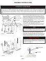
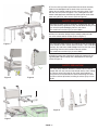
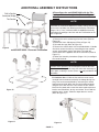
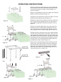
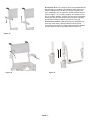
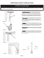
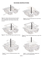
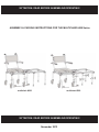
!ATTENTION: READ BEFORE ASSEMBLING/OPERATING!
ASSEMBLY & PACKING INSTRUCTIONS FOR THE MULTICHAIR 6000 Series
multichair 6000
multichair 6200
!ATTENTION: READ BEFORE ASSEMBLING/OPERATING!
November 2012
ASSEMBLY INSTRUCTIONS
!ATTENTION: PLEASE READ!
Please see LIMITED WARRANTY of these instructions. If the warranty is not acceptable, contact Nuprodx, Inc. for information about
returning the chair for a refund (Restocking fees and shipping charges will be applied). This chair is designed and intended for indoor
shower and bathroom use. It is not designed for outdoor use and will void the warranty if used in this fashion. If thresholds, shower
curbs or barriers are encountered that exceed ½” in height, the area in question should be brought within the code for disabled accessibility.
Roll-in Section
Connector Bridge
Tub Section
A The multiCHAIR 6000 and 6200 (Refer to Figure 1) are composed of three sections: the roll-in section with offset legs and 5”
casters, the connector bridge section, and the tub section which
has straight legs and adjusting feet. The chair is shipped standard
with the tub section positioned on the user’s left side.Unpack all
parts from the shipping carton.
B Remove all tape and/or packing from the chair. Keep shipping
materials for future use. Note the location of padding materials
and sheet-plastic which protects parts of your chair.
C Position the frames upside down and install the legs (Refer to
Figure 2): The roll-in frame has caster legs and the tub section
has stationary legs.
NOTE!
If you need to position the chair so the tub is on the user’s right
side, refer to the Additional Assembly Instructions on Page 3.
Figure 1
multiCHAIR 6000
D Position the roll-in legs so that the offset points out at a 45degree angle. Note the small pin that mates with holes in the
frame. Make sure that the legs slide “home” into the socket of the
seat frame. Use the included ¼” Allen wrench to securely tighten
the bolts located at the corners of the frame (Refer to Figure 3).
SAFETY PRECAUTION!
If any of the legs are not fitted correctly into the socket of the seat
frame or are not securely tightened there is an extreme risk of the
legs dislodging completely from the chair. This could cause serious injury or even death!
offset leg with
pin
seat frame
Figure 2
Figure 3
- PAGE 1 -
F Turn the chair right side up and install the backrest assembly.
Slide the two backposts into the back of the seat frame and
tighten the two socket head cap screws using the yellow T-handle Allen wrench (Refer to Figures 4 & 5). Also tighten the four
button head capscrews that attach the back cushion to the back
posts using the 5/32” Allen wrench (Refer to Figure 6).
SAFETY PRECAUTION!
Both backrest posts must be completely engaged with the seat
frame and securely tightened. If they are not fitted correctly, there
is a risk of the posts dislodging from the seat frame.
This could cause serious injury or even death!
G Place the connector bridge into the matching holes on both
the roll-in section and tub section (Refer to Figure 7).
SAFETY PRECAUTION!
The connector bridge must be fully seated into the corresponding
holes of both the roll-in section and tub section. If this is not done
correctly, the seat frame could dislodge itself from the chair when
transferring from the roll-in section to the tub section.
This could cause serious injury or even death!
Figure 4
H Install the swing-away footrests by sliding the gooseneck tubing/foot paddle into the clamp that is attached to the front legs
(Refer to Figure 8).
SAFETY PRECAUTION!
Figure 5
Figure 6
The swing-away footrests should be installed into the footrest
clamps after the user has been transferred into the chair. Putting
an extreme amount of weight on the swing-away footrests or
using them as an assistive device when transferring can cause
the entire chair to tip forward, resulting in serious injury or even
death!
Figure 8
Figure 7
- PAGE 2 -
ADDITIONAL ASSEMBLY INSTRUCTIONS
A Reconfigure the multiCHAIR 6000 with the Tub
Section on the user’s right side (Refer to Figures 9,
10 & 11):
Roll-in Section
Connector Bridge
Tub Section
NOTE!
Assemble the multiCHAIR 6000 to the factory setting (with the tub
on the user’s left side) first, following the Assembly Instructions
(Pages 1 & 2). Then, if desired, follow the Additional Assembly
Instructions to reconfigure the chair with the Tub Section on the
user’s right side.
Figure 9
multiCHAIR 6000 - Reversed Orientation
1) Remove the roll-in section legs from the frame (Refer to
Figure 10)
2) Rotate the frame 180 degrees (Refer to Figure 10)
3) Re-install the legs (Refer to Figure 10)
4) Reverse the release latch: Use the provided black L-Handle
wrench to remove the latch by unscrewing the two machine
screws, which attach it to the seat frame. Re-install the
release latch on the opposite side of the seat frame (Refer to
Figure 11).
5) Follow the Assembly Instructions (Pages 1 & 2) to configure
the rest of the chair.
NOTE!
Release Latch Assembly: Do not attempt to unscrew the inner
slotted screws. Doing so can cause the entire latch assembly to
come apart, rendering it useless (There is no tool provided for this
operation) .
B Cantilever Arms: If desired, the cantilever arms can be
removed from the backrest assembly for storage during traveling. This can be accomplished by unscrewing the socket
head cap screws that attach the arms to the backrest posts
using the 5/32” Allen wrench. Then remove the arm assemblies from the posts and re-insert the socke head cap screws
into the arm assemblies, so they are not lost. To re-install the
cantilever arms, simply follow the steps above in reverse
(Refer to Figure 12).
Figure 10
(2) Machine
Screws
Figure 11
Figure 12
- PAGE 3 -
OPERATING INSTRUCTIONS
A Ensure all fasteners (bolts/washers) are securely tightened
and all chair parts have been assembled correctly (Refer back
to Assembly Instructions if needed. Contact Nuprodx, Inc. if
unsure of anything).
B Place the assembled tub section of the slider into the desired
position of the bath tub (Refer to Figure 13).
C Position the assembled roll-in section of the slider next to the
outside wall of the bath tub (Refer to Figure 14).
D Adjust the height of the tub section to match the height of the
roll-in section by either adjusting the four inner legs (tub section) and/or the adjustable crutch tips (tub section) - Refer to
Figure 15.
Figure 13
E Insert the connector bridge into the four eyelet holes (Two
located on the roll-in section and two located on the tub section) - Refer to Figure 16. Switch the four shoulder screws to
the lock position on the connector bridge (Refer to Figure 17).
F Release the latch mechanism on the roll-in section and slide
the slider seat assembly onto the tub section, making sure the
latch engages fully and locks in place. If the roll-in section and
tub section are not level in height or out of alignment, the slider
seat assembly will not function correctly and safely. To ensure
the safety of the user, make adjustments to both sections as
needed and retry Step F (Refer to Figure 18).
Figure 14
Inner Leg
Adjustment
G Remove the connector bridge to test the stability of the tub
section. Also, ensure that the slider seat frame is locked into
place and will not remove during use. Once this is complete,
replace the connector bridge and slide the slider seat frame
back to the roll-in section. The connector bridge can then be
removed and the chair is ready for use.
Crutch Tip
Adjustment
Figure 17
Figure 15
Figure 18
Figure 16
- PAGE 4 -
D Cantilever Arms: The cantilever arms can be adjusted to the
desired height by completing the following steps: Loosen the
socket head cap screws on the arm clamps, raise/lower the
arms accordingly, then re-tighten the socket head cap screws
(Refer to Figure 19). For safety purposes, the cantilever arms
lock in the down position. To switch the arms to the up position,
simply push the arms toward the back of the chair (releasing
the locking mechanism) and lift up (Refer to Figure 20).
E Footrest Assemblies: Footrest clamps are installed on the
front legs at the factory. Slide the footrest into the clamp.
Loosen the pinch bolt on the footrest clamp and slide up/down
as required by the user’s leg length (Refer to Figure 21).
Figure 19
Figure 21
Figure 20
- PAGE 5 -
ADDITIONAL SAFETY PRECAUTIONS
!ATTENTION: PLEASE READ!
WARNING! Failure to account for the afformentioned and the following safety precautions can result in serious
injury to the user or even death!
A Leg Height Adjustment: When making height adjustments to
any of the legs, make sure that the brass buttons are fully
engaged into the outer legs. If pushed too hard the button
could become stuck inside the inner leg (Contact Nuprodx, Inc.
if this occurs). Leg height adjustment should only be made
before transferring the user into the chair (Refer to Figure 22).
A
B Caster Wheels: When transferring into the chair, out of the
chair and sliding the user from the roll-in section into the tub
section, all four caster wheels should be securely locked in
place. Failure to do so could cause the chair to become unstable (Refer to Figure 23).
Figure 22
C Fasteners: Over time the screws and washers on the chair
may become loose. It is very important that these are checked
and securely tightened before each use. Failure to do so could
cause a part to dislodge from the chair (Refer to Figure 24).
B
D Release Latch: Verify that the release latch is fully engaged
on the slider seat before removing the connector bridge (Refer
to Figure 25).
Figure 23
E Leveling: The roll-in and tub sections must both be level and
equal in height. To further adjust the height on the tub section
legs, rotate the crutch tip feet clockwise or counterclockwise
(Refer to Figure 26).
C
Figure 24
Release Latch
Figure 26
Figure 25
- PAGE 6 -
LIMITED WARRANTY
A WARRANTY ACTIVATION Please read this warranty before operating or using your multiCHAIR. To activate the
warranty on your multiCHAIR register it online (www.nuprodx.com/form-registration/index.htm) or by phone. By operating or using the chair, you agree to the terms of this warranty.
B WARRANTY: Nuprodx, Inc. warrants this product against defects in material and workmanship as follows: There is
a 10-Day conditional money-back warranty. During this time period, the customer is permitted to try out the
multiCHAIR, fully-clothed, keeping the chair in “like new” condition (NOTE: “Like new” condition, in terms of the
multiCHAIR, is defined by Nuprodx, Inc. as no visible wear/usage/water marks for the multiCHAIR to be accepted and
refunds issued when returned to Nuprodx, Inc.). If the customer decides that the multiCHAIR will not work for them,
before the 10-Day period has passed and with the authorization of Nuprodx, the chair can be returned for a full refund
minus a 10% restocking charge (NOTE: The customer is responsible for both in-bound and out-bound freight). After
the initial 10-Day period has passed, there is a two-year limited warranty for all parts of the chair, with the exception of
the seat and back cushions (NOTE: Because of the fragile nature of the foam, there is no warranty for the cushions).
The warranty does not cover normal “wear and tear” from everday use of the product and custom parts/custom cushions
are also excluded from the warranty and cannot be returned for a refund under any circumstances. Please see section E
WARRANTY LIMITATION AND EXCLUSIONS for more info on warranty exclusions.
C The warranty period begins on the date you receive the chair. For warranty service, please contact Nuprodx, Inc. no
later than one month following the applicable warranty term. The chair will be repaired or replaced at the discretion of
Nuprodx, Inc. with no charges to you for parts and labor, provided you have proof of purchase and of purchase date.
D DISCLAIMER: Except for the above warranty, and the acknowledgement by Nuprodx, Inc. that the chair, as manufactured by it, is fit for the general purpose for which most persons acquire a chair of its kind, Nuprodx, Inc. provides
that you accept the chair as is, without warranties, either express or implied. Nuprodx, Inc. makes no warranty of fitness for your particular purpose and no warranty of merchantability beyond that already stated. No warranties extend
beyond the duration of the express warranty stated above.
E WARRANTY LIMITATIONS AND EXCLUSIONS: The only obligation of Nuprodx, Inc. is to provide the purchaser
with free repair and replacement as described above. This exclusive warranty remedy will not have failed as long as
Nuprodx, Inc. is willing and able to repair or replace as described, but if this remedy should be held to have failed, the
only remaining warranty obligation of Nuprodx, Inc. shall be to refund the acts beyond the control of Nuprodx, Inc. The
warranty does not cover normal “wear and tear” from everday use of the product. Standard seat/back cushions/custom
parts/custom cushions are not covered under the warranty.
F This warranty gives you specific legal rights, and you may have other rights that may vary from state to state.
G This warranty does not apply to problems arising from normal wear, improper operation, improper maintenance,
improper storage or similar disclaimer of implied warranties, and some do not allow limitations on how long an implied
warranty may last. Some do not allow exclusion or limitation of incidental or consequential damages. So the above
limitations or exclusions may not apply to you.
H RETURN INSTRUCTIONS In the event that you need to return the Nuprodx multiCHAIR, please follow the instructions below:
1) Review the information contained in your warranty to see if this applies to you
2) Obtain a Return Authorization # from Nuprodx, Inc.
3) Re-package the entire chair and its contents in the original packaging and ship to the following address:
Nuprodx, Inc.
c/o PNM Company
Attn: RMA# xxxx
2547 N. Business Park Ave.
Fresno, CA 93727
4 Malone Lane, San Rafael, CA 94903
(415) 472-1699, (415) 492-1396 fax, (855) 220-5171 toll free, [email protected]
- PAGE 7 -
PACKING INSTRUCTIONS
Figure A - Drape the black strap across the bottom
of the carrying case (not shown for clarity). Place
the inverted shuttle & roll-in section frames inside
the case.
Figure B - Place the plastic panel over the inverted
cushion and frame.
Figure C - Place the foam ring on top of the frame.
Figure D - Place the tub section frame on top of the
foam ring.
Figure E - Center the folded footrests down inside
the frames.
Figure F - Position the hourglass shaped foam
piece on top of the folded footrest.
- PAGE 8 -
Figure G - Place the tub section legon top of the
hourglass shaped foam.
Figure I - Place the connector bridge and
foam on top of the legs with casters.
Figure H - Place the legs with casters in the black
plastic tray and center it over the tub section legs.
Figure J - Wrap the black strap tightly around the completed package and position the cantilever arms along
side it. Finally place the backrest assembly on top
4 Malone Lane, San Rafael, CA 94903
(415) 472-1699, (415) 492-1396 fax, (855) 220-5171 toll free, [email protected]
- PAGE 9 -