1
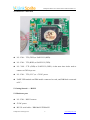
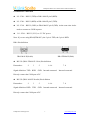
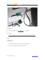
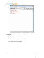
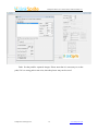
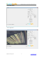
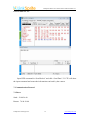
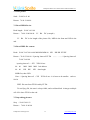
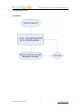
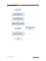
LinkSprite JPEG Color Camera Serial UART Interface User Manual July, 2013 LinkSprite Technologies, Inc www.linksprite.com LinkSprite JPEG Color Camera Serial UART Interface V1.1 Doc Title Version LinkSprite JPEG Color Camera Serial UART Interface User Manual Number LS-Y201-2MP Version 1.2 Date Description 1.0 31/03/2012 The first edition Nancy 1.1 04/07/2012 The second edition Nancy 1.2 16/07/2013 The third edition Nancy LinkSprite Technologies Inc. 2 Author www.linksprite.com LinkSprite JPEG Color Camera Serial UART Interface V1.1 Table of Content 1. Introduction ................................................................................................................ 4 2. Specification............................................................................................................... 4 3. Application................................................................................................................. 5 4. Getting Started - TTL................................................................................................. 5 4.1 Hardware part ....................................................................................................... 5 4.2 Hardware connection............................................................................................ 6 5. Getting Started——RS232 ........................................................................................ 6 5.1 Hardware part ....................................................................................................... 6 5.2 Hardware connection............................................................................................ 7 5.3 Hardware connection............................................................................................ 8 5.4 Software ............................................................................................................... 8 6. Test............................................................................................................................. 8 6.1 Regular test........................................................................................................... 8 6.2 Software ............................................................................................................... 9 6.3 Test with software .............................................................................................. 11 6.4 Test with X-CTU................................................................................................ 12 7. Communication Protocol ......................................................................................... 12 7.1 Reset ................................................................................................................... 12 7.2 Take picture ........................................................................................................ 13 7.3 Read JPEG file size ............................................................................................ 13 7.4 Read JPEG file content ...................................................................................... 13 7.5 Stop taking pictures ............................................................................................ 13 7.6 Compression Ratio ............................................................................................. 14 7.7 Image size........................................................................................................... 14 7.8 Power Saving...................................................................................................... 14 7.9 Changing Baud Rate........................................................................................... 14 8. Program flow chart................................................................................................... 16 8.1 Initialize.............................................................................................................. 16 8.2 Take JPEG picture:.......................................................................................... 17 LinkSprite Technologies Inc. 3 www.linksprite.com LinkSprite JPEG Color Camera Serial UART Interface V1.1 1. Introduction LS-Y201-2MP is LinkSprite’s new generation serial port camera module. It can capture high resolution pictures using the serial port. LS-Y201-2MP is a modular design that outputs JPEG images through UART, and can be easily integrated into existing design. 2. Specification VGA/QVGA/160*120 resolution Support capture JPEG from serial port Default baud rate of serial port is 115200 DC 5V power supply Size 32mm X 32mm Current consumption: 80-100mA Near the C03 pin is AV output, this is a analog output pin. Footprint LinkSprite Technologies Inc. 4 www.linksprite.com LinkSprite JPEG Color Camera Serial UART Interface V1.1 3. Application Different image capture systems Environmental monitoring Industry monitoring Medical equipment Video phone Security Vehicle based GPS 4. Getting Started - TTL 4.1 Hardware part LS - Y201 – TTL camera 5V DC power UART-232 module LinkSprite Technologies Inc. 5 www.linksprite.com LinkSprite JPEG Color Camera Serial UART Interface V1.1 4.2 Hardware connection LS - Y201 - TTL (TXD) to UART-232 (RXD). LS - Y201 - TTL (RXD) to UART-232 (TXD). LS - Y201 - TTL (GND) to UART-232 (GND). At the same time it also need to connect to GND in power. LS - Y201 - TTL (VCC) to +5V DC power. UART-USB module and DB9 needle connected to each, and DB9 hole connected to PC。 5. Getting Started——RS232 5.1 Hardware part LS - Y201 - RS232 camera 5V DC power RS-232 serial cable(DB9 MALE/FEMALE) LinkSprite Technologies Inc. 6 www.linksprite.com LinkSprite JPEG Color Camera Serial UART Interface V1.1 5.2 Hardware connection LS - Y201 - RS232 (TXD) to DB-9 MALE pin 2(RXD). LS - Y201 - RS232 (RXD) to DB-9 MALE pin 3(TXD). LS - Y201 - RS232 (GND) to DB-9 MALE pin 5(GND). At the same time it also needs to connect to GND in power. LS - Y201 - RS232 (VCC) to +5V DC power. Note: If you are using DB-9(FEMALE), the 2 pin is TXD, the 3 pin is RXD. DB-9 Pin definition DB-9 MALE(Needle) DB-9 FEMALE(Hole) RS-232 (DB-9 FEMALE / Hole) Pin definition Pin number: 2 Signal definition: TXD 3 RXD 5 1. 4. 6 GND Internal connected 7. 8 Internal connected Directly connect the COM port of PC RS-232 (DB-9 MALE/ Needle) Pin definition Pin number: 2 Signal definition: RXD 3 TXD 5 1. 4. 6 7. 8 GND Internal connected Internal connected Directly connect the COM port of PC LinkSprite Technologies Inc. 7 www.linksprite.com LinkSprite JPEG Color Camera Serial UART Interface V1.1 5.3 Hardware connection 5.4 Software X-CTU Download Link:www.digi.com Software: (test software) http://www.linksprite.com/download/showdownload.php?id=36&lang=en 6. Test 6.1 Regular test Power up information in X-CTU as the following ASCII: Please note that the baud rate should be 115200. LinkSprite Technologies Inc. 8 www.linksprite.com LinkSprite JPEG Color Camera Serial UART Interface V1.1 6.2 Software Com Port:Choose the right Com Port。 Data Port:Baud Rate settings, here it is 115200。 Click ―Open‖ to open Com connection LinkSprite Technologies Inc. 9 www.linksprite.com LinkSprite JPEG Color Camera Serial UART Interface V1.1 Path:Set the path for captured images. Please note that it is necessary to set the path, if it is a wrong path or not exist, then the picture may not be saved. LinkSprite Technologies Inc. 10 www.linksprite.com LinkSprite JPEG Color Camera Serial UART Interface V1.1 6.3 Test with software Click ―Single Shot‖: LinkSprite Technologies Inc. 11 www.linksprite.com LinkSprite JPEG Color Camera Serial UART Interface V1.1 6.4 Test with X-CTU Input HEX command in ―Send Packet‖ and click ―Send Data‖,X-CTU will show the input command and return the information sent back by the camera. 7. Communication Protocol 7.1 Reset Send:56 00 26 00 Return:76 00 26 00 LinkSprite Technologies Inc. 12 www.linksprite.com LinkSprite JPEG Color Camera Serial UART Interface V1.1 7.2 Take picture Send:56 00 36 01 00 Return:76 00 36 00 00 7.3 Read JPEG file size Read length:56 00 34 01 00 Return :76 00 34 00 04 00 2C 2C B4 DC (example) B4 DC is the length of the picture file, MSB in the front and LSB in the end. 7.4 Read JPEG file content Read:56 00 32 0C 00 0A 00 MM MM MM 00 KK Return :76 00 32 00 00 (Spacing Interval)FF D8 KK KK XX XX 。。。……。。。 (Spacing Interval) 76 00 32 00 00 (spacing interval)= XX XX*0.01ms 00 00 MM MM MM 00 00 KK KK KK Init address data length MSB first, then LSB Note: (Spacing Interval)= XX XX*0.01ms,it is better to be smaller,such as: 00 0A JPEG file start from FF D8 end by FF D9. To read Jpeg file, the start is always 0000, and read data block in integer multiple of 8 till it show FF D9 at the end. 7.5 Stop taking pictures Stop :56 00 36 01 03 Return :76 00 36 00 00 LinkSprite Technologies Inc. 13 www.linksprite.com LinkSprite JPEG Color Camera Serial UART Interface V1.1 7.6 Compression Ratio Send:56 00 31 05 01 01 12 04 XX Return:76 00 31 00 00 XX is usually 1-9. 7.7 Image size Send Resolution Return 56 00 54 01 22 160*120 76 00 54 00 00 56 00 54 01 11 320*240 76 00 54 00 00 56 00 54 01 00 640*480 76 00 54 00 00 56 00 54 01 1D 800*600 76 00 54 00 00 56 00 54 01 1C 1024*768 76 00 54 00 00 56 00 54 01 1B 1280*960 76 00 54 00 00 56 00 54 01 21 1600*1200 76 00 54 00 00 Do not disconnect or reset after sending the command, or it will turn back. 7.8 Power Saving Send: 56 00 3E 03 00 01 01 Return :76 00 3E 00 00 Quit Saving:56 00 3E 03 00 01 00 Return:76 00 3E 00 00 7.9 Changing Baud Rate Send :56 00 24 03 01 XX Return :76 00 24 00 00 XX baud rate LinkSprite Technologies Inc. 14 www.linksprite.com LinkSprite JPEG Color Camera Serial UART Interface V1.1 0Xae 9600 0X2A 38400 0X1C 57600 0X0D 115200 0X7E 128000 0X56 256000 Please Note: The starting read address must be the 8 integer multiples For multiple cameras 56 XX 36 01 00,XX is the Device Number( Default is 00 ) UART is in RS232 level. If connect to the MCU, please add a level converter or re move the MAX3232 ic. RS232 level are used in the modules,UART communication distance can not be longer than 1m. The serial port will show the below info when connect with powe r: Init end The host only have to make sure when to receive “Init end”(36 32 35 0D 0A 49 6E 69 74 20 65 6E 64 0D 0A), then take the capture command in 2-3s. LinkSprite Technologies Inc. 15 www.linksprite.com LinkSprite JPEG Color Camera Serial UART Interface V1.1 8. Program flow chart 8.1 Initialize LinkSprite Technologies Inc. 16 www.linksprite.com LinkSprite JPEG Color Camera Serial UART Interface V1.1 8.2 Take JPEG picture: LinkSprite Technologies Inc. 17 www.linksprite.com LinkSprite JPEG Color Camera Serial UART Interface V1.1 LinkSprite Technologies, Inc. Add:1067 S Hover St, Unit E-186, Longmont, CO 80501 Tel:720-204-8599 Email:[email protected] Web:www.linksprite.com LinkSprite Technologies Inc. 18 www.linksprite.com