1
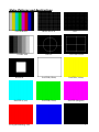
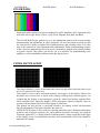
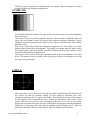
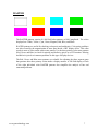
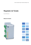
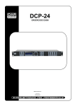
GME User’s Manual Rev 1.3 TEST INSTRUMENT SAFETY GUIDELINES WARNING An electrical shock of over 10 milliamps of current to pass through the heart will stop most human heartbeats. Voltage as low as 35 volts dc or ac rms should be considered dangerous and hazardous since it can produce a lethal current under certain conditions. Be sure to observe following safety precautions: 1. Do not expose high voltage needlessly in the equipment under test. Remove housings and covers only when necessary. Turn off equipment while making test connections in high-voltage circuits. Discharge high-voltage capacitors after removing power. 2. If possible, familiarize yourself with the equipment being tested and the location of its high voltage points. However, remember that high voltage may appear at unexpected points in defective equipment. 3. Use an insulated floor material or a large, insulated floor mat to stand on, and an insulated work surface on which to place equipment; make certain such surfaces are not damp or wet. 4. When using a probe, touch only the insulated portion. Never touch the exposed tip portion. 5. When testing ac powered equipment, remember that ac line voltage is usually present on some power input circuits such as the on-off switch, fuses, power transformer, etc. any time the equipment is connected to an ac outlet, even if the equipment is turned off. Limited One-Year Warranty GME Technology warrants to the original purchaser that this product and the component parts thereof, will be free from defects in workmanship and materials for a period of one years from the data of purchase. GME Technology will, without charge, repair or replace, at its’ option, defective product or component parts. Returned product must be accompanied by proof of the purchase date in the form a sales receipt. Term and Conditions The warranty period is based upon the invoice date of the original purchase by the end-user. Warranty only applies to defects in materials and/or workmanship, which occur during normal use. Warranty does not apply to those products that are damaged due to misuse, abuse, negligence or modification. Warranty does not extend to any damage that occurs in shipment or due to natural phenomenon (i.e. lightning or line surges). Warranty will be voided if the original serial number on the product is removed by accident or intentionally This warranty gives you specific rights and you may have other rights, which vary from state-to-state. Service & Repair The following are procedure for returning a GME product for servicing and repair. Turn around time for repair is normally within five (5) working days excluding shipping time. RMA Procedure Before sending your GME product in for service, be sure to contact GME Technology first to obtain a RMA number. If your product is still under warranty, please send in the product along with a copy of the receipt showing the date when the product was purchased. If the warranty has already expired, please ask for the repair cost when you contact GME Technology for the RMA number and include a check or money order for the repair cost when you send in the product. Please make check payable to: GME Technology You may send your GME product to our service & repair department at: GME Technology ATTN: Service & Repair Department 380 S. East End Ave., #H Pomona, CA 91766 Be sure to include a note showing your RMA number, your name, telephone number, return address, and a description of the problem with the product. For the most recent support information, please visit GME Technology website at www.gmetechnology.com/support Table of Contents Page Introduction …………………………………………………………………………. 1 Item Checklist ……………….…………………………………………………….... 1 Features ……………………………………………………………………………... 1 Understanding the Front Panel …………………………………………………….... 2 Basic Operation ……………………………………………………………………... 3 Video Patterns and Applications ………………………………………………….... 4-8 Specifications ………………….……………………………………………………... 9 GME Product Information ………………………………………………………....… 10 Notes ……….………………….……………………………………………………... 11 Introduction Thank you for purchasing the PG-38 NTSC Pattern Generator. This is an easy-to-use handheld video pattern generator that generates a wide variety of test patterns for comprehensive testing, calibration, and repair of NTSC television and other video equipments. The PG-38 delivers the quality and functionality you would expect from an expensive high end NTSC pattern generator at a very affordable price. With its easy to understand interface, the PG-38 is designed to meet the need of people from all levels ranging from novice to video professionals. The PG-38 features a wide selection of popular video patterns including Color Bars, Crosshatch, Dot, Staircase, Circle, Center Cross, Window, and Raster for accurate and comprehensive TV troubleshooting and testing. It also supports both progressive and interlace scanning system. RF video is output on Channel 3 with 1kHz audio tone for audio troubleshooting. Item Checklist One PG-38 NTSC pattern generator One User’s Manual Features 8 commonly used video test patterns including COLOR BARS, CROSS HATCH, DOT, STAIRCASE, CIRCLE, CENTER CROSS, WINDOW, and RASTER (choose from White, Yellow, Cyan, Green, Magenta, Red, Blue, and Black) Single push button selectable patterns with hold down reverse Selectable progressive and interlace scanning system Composite video and S-Video output RF output on Channel 3 with 1kHz audio test tone (BNC connector) AC adaptor power source or standard 9V battery operation Low battery indicator Ideal for on-the-bench and in-the-field testing Easy to use, lightweight, and portable Understanding the Front Panel 1. Power ON/OFF switch This Power ON/OFF switch is on the left side of the unit. Slide the switch upward to turn the unit on and downward to turn the unit off. 2. Power ON/OFF LED 7 8 9 2 4 1 Power is ON when the LED lights up and power is OFF when the LED is off. 3 3. Battery Low LED When the PG-38 is operating on a standard 9V battery and the voltage on the battery has drop down to around 5V, this green LED will turn on indicating the voltage on the battery is low. 5 4. 9V AC adaptor input The user may connect a 9V 100mA 5.5mm x 2.1mm center positive AC adaptor (not included) to power the PG38. 6 5. Scanning Format switch Use this selector to choose between PROGRESSIVE or INTERLACE scanning system. 6. Video Pattern button Use this button to cycle through one of the following video patterns: COLOR BARS CROSS HATCH DOT STAIRCASE CIRCLE CENTER CROSS WINDOW RASTER NOTE: Holding down this button will display previous patterns in reverse order until COLOR BARS pattern is reached. 7. RF Video Output (BNC connector) RF video is output on Channel 3 with 1kHz audio test tone. Connect this to the TV’s antenna connector and switch to Channel 3 for video signal. 8. S-Video output Connect this to TV’s s-video input for video signal 9. Composite Video Output (RCA connector) Connect this to TV’s composite video input for video signal www.gmetechnology.com 1 Basic Operation 1. Choose the scanning system you prefer using the Scanning Format selector. 2. Connect the appropriate video output (choose from RF, S-video, and Composite video) to the corresponding inputs of the equipment under test. 3. Slide the power switch to turn on the PG-38. 4. Push the video pattern button to step to the desire video pattern for display. Available video patterns include COLOR BARS, CROSS HATCH, DOT, STAIRCASE, CIRCLE, CENTER CROSS, WINDOW, and RASTER (choose from White, Yellow, Cyan, Green, Magenta, Red, Blue, and Black). **NOTE: Holding down the video pattern button will display previous patterns in reverse order until COLOR BARS pattern is reached www.gmetechnology.com 2 Video Patterns and Applications COLOR BARS STAIRCASE WINDOW RASTER (Cyan) www.gmetechnology.com CROSS HATCH CIRCLE DOT CENTER CROSS RASTER (White) RASTER (Yellow) RASTER (Green) RASTER (Magenta) 3 RASTER (Red) RASTER (Blue) RASTER (Black) COLOR BARS Eight equal width vertical color bars are displayed at 100% amplitude, 100% saturation in the order from left to right: White, Yellow, Cyan, Green, Magenta, Red, Blue, and Black. The COLOR BARS video pattern serves as the fundamental pattern used for most testing, troubleshooting and adjustments in video equipment. Use this test pattern to check and test the video device’s ability to produce fully saturated primary and secondary colors. It is often used as the reference for color adjustment and compensation. When troubleshooting, analysis of the colors bars pattern helps television service personnel to pinpoint color related problem to specific circuits. This pattern can also be use as a reference for troubleshooting color amplifier or color demodulator problems inside the display device. CROSS HATCH & DOT This pattern displays a series of horizontal and vertical straight white lines that forms a grid of 16 x 12 squares of the same size. This pattern is used to check and adjust dynamic convergence of the display. Observe the horizontal and vertical lines to detect color fringing resulting from misconvergence. An example that the display is misconverged is when the white lines become separated Red, Green, and Blue lines. Adjust the display’s RGB convergence control to align the colors to overlap so the horizontal and vertical lines appear as white lines. This pattern can also provide a convenient reference for making vertical and horizontal linearity adjustments. Each square should be the same size. CROSS HATCH pattern is also useful for checking pincushion (bow) distortion and display geometry such as picture centering, size, and trapezoid (keystone) correction. For trapezoid correction, adjust the TV’s display control so that the pattern’s edges are parallel to the edges of the display screen. For pincushion correction, the horizontal and vertical lines should be adjusted to be straight. www.gmetechnology.com 4 The DOT pattern is preferred for checking static convergence. Static convergence is always performed before and after purity adjustments. STAIRCASE The STAIRCASE pattern displays six equal-width vertical bar steps of increasing luminance from left to right. This pattern is useful in checking amplifier linearity. The increment of amplitude from one step to the next should be equal. Non-equal steps represent non-linear distortion. Typical luminance nonlinear distortions will result in a loss of grey-scale distinctions, which means that detail is loss. Each of the vertical bars should have distinctive brightness level. The display is too dark when the black vertical bars blend together. The display is too bright when the white vertical bars blend together. Adjust the display cutoff/bias controls and drive/gain controls so each vertical bar has distinctive brightness level. This pattern is also useful for checking and adjusting the grayscale performance of a video device. This pattern is seen as a primary color (red, green, or blue) tint on display device with poor grayscale performance. CIRCLE This pattern shows a 4:3 aspect ratio circle that is perfectly round and one horizontal line and one vertical line that are perfectly straight. Use this pattern to determine your video equipment’s alignment for a 4:3 aspect ratio display. There should be a perfect circle centered on your display with a horizontal line and a vertical line intersecting at the center of the screen. This test can be used to test a misaligned deflection coil as well. If the monitor displays the test pattern off to one side, this would indicate an improper centering adjustment. Titled lines or squeezing of the circle indicate problems with the display device. Check for tilted line to determine the areas of the monitor where the display is not consistent. www.gmetechnology.com 5 CENTER CROSS The CENTER CROSS pattern should intersect at the center of the screen and the lines should not be tilted. If the centering is not exact, adjust the display device with the centering control. Improper centering can be due to a deflection circuit fault. If the display is tilted, repositioning of the deflection yoke may correct the problem. This pattern also provides a good general check of vertical and horizontal sync. WINDOW The WINDOW pattern displays a centered white window on black background. Use this pattern to measure the chromaticity of the display device. This pattern is preferred over the full field white raster because the WINDOW pattern more closely duplicates the APL (average picture level) of typical program material and does not unnaturally stress display circuits. For gray-scale tracking, the WINDOW can be set to low luminance for adjusting cutoff controls and high luminance for adjusting drive controls. www.gmetechnology.com 6 RASTER The RASTER patterns consist of 8 full field color patterns at 100% amplitude. The colors displayed are: White, Yellow, Cyan, Green, Magenta, Red, Blue, and Black. RASTER patterns are useful for checking color purity and uniformity. Color purity problems are often caused by the magnetization of some parts inside a CRT display device. This often results in areas of color on the white raster pattern. Use the three primary color raster patterns (Red, Green, and Blue) to check for missing and defective pixels on a LCD monitor. Missing and defective pixels are common problems on this type of display devices. The Red, Green, and Blue raster patterns are valuable for adjusting the three separate guns that generate these three primary colors inside a display monitor. A full field display of each of the eight individual color RASTER patterns also simplifies the analysis of hue and saturation problems. www.gmetechnology.com 7 Specifications Video Patterns COLOR BARS CROSS HATCH DOT STAIRCASE CIRCLE CENTER CROSS WINDOW RASTER (White, Yellow, Cyan, Green, Magenta, Red, Blue, and Black Scanning System Interlace and Progressive RF Output Composite Video S-Video Channel 3 (61.25MHz), crystal controlled 1.0Vp-p into 75Ω Chrominance output: 0.6Vp-p into 75Ω Luminance plus Sync output: 0.8Vp-p into 75Ω Sound 1 kHz audio tone Power one standard 9V battery OR 9V AC adaptor (100mA, 5.5mmx2.1mm center positive) Dimension 5.7"(H) x 3.8"(W) x 1.5"(D) Weight 0.8 lb www.gmetechnology.com 8 WWW.GMETechnology.COM For product updates and information CHECK OUT THESE OTHER TEST EQUIPMENT AVAILABLE FROM GME GME offers many different types of electronic test equipment to suit your needs. Here are some of the test equipment products we offer. Model Description HG139 HDTV Pattern Generator SG-10 10 MHz DDS Signal Generator 236 In-Circuit ESR & DCR Capacitor Tester PG-16A NTSC & Monitor Tester (Handheld Model) PG-68 NTSC & Monitor Tester (Benchtop Model) PG-38 NTSC Pattern Generator MT-160 Computer Monitor Tester LC200 Digital LC Meter C350 Capacitance Meter Other products such as digital / analog panel meters, step motor drivers are also available. Please visit our website at www.gmetechnology.com for complete detail. www.gmetechnology.com 9 Notes www.gmetechnology.com 10