1
53
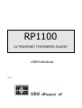
ULTRASONIC THICKNESS GAUGE
USER MANUAL
Rev. 0
1 INDICE
1
INDICE ........................................................................................................................................................................ 2
2
INTRODUCTION........................................................................................................................................................ 3
2.1
2.2
2.3
2.4
2.5
2.6
2.7
FEATURES........................................................................................................................................................... 4
STANDARD KIT .................................................................................................................................................. 4
DESCRIPTION ..................................................................................................................................................... 5
MEASURING PRINCIPLE ........................................................................................................................................... 6
LCD ...................................................................................................................................................................... 6
COUPLING........................................................................................................................................................... 6
BATTERY ............................................................................................................................................................ 7
3
HOW TO START ........................................................................................................................................................ 8
4
HOW TO MEASURE.................................................................................................................................................. 8
5
PROBE SELECTION AN PROBE “ZERO SETTING” ............................................................................................ 8
VISUALIZATION AND/OR MODIFICATION OF VELOCITY VALUE........................................................................ 9
CALIBRATION OF VELOCITY VALUE.......................................................................................................................... 9
4
MESSAGES SHOWN ON LCD ................................................................................................................................ 10
7
WARNING................................................................................................................................................................. 11
6
TECHNICAL FEATURES......................................................................................................................................... 12
7
STANDARD ACCESSORIES .................................................................................................................................... 12
8
ALLEGATO:DIAGRAMMA DI FLUSSO FUNZIONAMENTO RP1100................................................................ 14
2
2 INTRODUCTION
Thank you to have choosed our ultrasonic thickness gauge type RP 1100.
Before to use it you must read carefully this manual.
The RP 1100 is a simple thickness gauge with many different functions and good performances.
It is produced with late electronic technology and leave the factory after hours of tests.
For this reason we are sure you will be satisfied using it.
Do not esitate to signal us possible misfunctioning that will occurs in the time.
Our customers service is ever ready to eliminate eventual faults and to recovers the original features, as
well to certificate periodically the instrument.
3
2.1
•
FEATURES
Easing to use
To start to measure it is enought to switch on the unit because the RP 1100 keep in the memory the
preceding value of velocity and setting
•
Sound velocity setting
It is possibile mesure the thickness of a material for wich we do not know the sound velocity it we
have a sample of the same material of wich we know the thickness
•
Automatic switch off
The RP 1100 automatically switch off if it does not works for 10 minutes
•
Sound velocity and probe “zero setting” are automatic storied
The sound velocity and the probe “zero setting” are atomaticly stored in the unit thanks to a memory
chip and to the battery.
2.2
STANDARD KIT
In the transportation bag you will find::
•
•
•
•
•
•
•
This manual
RP 1100 thickness gauge
Twin crystal probe Φ 10 mm 4 MHz
The battery charger
The couplant dispenser
The testing certificate
The guarantee certificate
It is recommended to avoid strong shock the RP 1100 instrument because some components (as the
LCD, glass made), can be damaged.
Keep the transportation bag, to recover the unit and all the accessories when not in use.
4
2.3
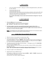
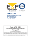
DESCRIPTION
1
2
3
4
5
6
7
8
9
10
11
12
Transmitter probe connector
Receiving probe connector
Transportation belt juncture
LCD display
UP button
DOWN button
[ON/OFF] button
RP1100 serial number label with some velocità settino values
Battery cover. To replace batteries it is necessari to unscreww two screww under a plastic
cover. Three alkaline dry cells R68 or LR6 type or three NiCd AA ] 900 mA/h have to be inserted
Twin crystal probe with cable
Calibration block (5mm)
Battery charter connector
5
2.4
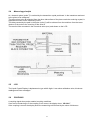
Measuring principle
An ultrasonic pulse (pulse T) is emitted by the transmitter crystal positioned in the transducer and sent
to the piece to be measured.
The echo pulse (echo B) reflected from the other side surface of the piece reach the receiving crystal, is
amplified and sent to time measuring circuit.
The delay caused by the path in the probe (echo S) will be subtract from the total time from the transmission of the echo to the receiving of the echo B.
The result will be converted in the numerical value (mm) and shown on the LCD.
2.5
LCD
The Liquid Crystal Display is alphanumeric type with 8 digits. It can show calibration value, thickness
readings and short messages.
2.6
COUPLING
A coupling signal show probe material coupling conditions.
If we are not measuring or if the coupling is not correct, the display show “NO ACC.”
If the coupling is correct the display show the measuring unit followed by the value of thickness
6
2.7
BATTERY
Checking of the battery charge
The display will show “LOW BATT” when the battery is empty.
Replace the cells or recharge the NiCd battery.
7
3 HOW TO START
1.
Insert 3 dry Alcaline Cells R6P or LR6 type or 3 NiCd rechargeable batteries ] 900 mA/h in
the RP 1100 unit
2.
Connect the probe to the unit
Connect the probe to the unit
Connect the cable of the probe to the two connectors positioned on the top of the RP 1100
Plug in the red connector in the side female connector and neutral connector in the internal female connector (see also DRWG NR 1).
Do not weld, disassembly or throw cells in the fire because is dangerous. They can
explose.
4 HOW TO MEASURE
1. Press the [ON] button for some seconds.
The LCD will displays in sequence the following indications:
RP1100
m/s xxxxx (stored velocity)
NO ACC..
ON
2. Put some couplant on the piece to be measured and apply the probe pushing a little.
The LCD shows the value of the thickness preceded by the measuring unit (mm or inches)
At the end of the measuring section push again the button [ON] for some seconds, the RP1100
will switch off, while the LCD shows [OFF]
NOTE: It is necessary to put some couplant on the surface of the piece to be measured to allow
the passage of ultrasonic beam through the inspected material
5
PROBE SELECTION AN PROBE “ZERO SETTING”
1. Select the velocity of the material to be measured (see. 2.4)
2. On the unit already switched on, push shortly the button “ON”
The LCD will display for a second “PROBE” , after will appear the type of probe precedently selected. By using the
button select the probe actually in use and press shortly the [ON] button. The LCD will shows [CAL. S+ N-], (calibration Y+ NO- ).
3. To calibrate the probe “zero setting push the button , it will appear on the LCD [CALXX.XX]
where xx.xx is the calibration value.
If you are using the calibration block built on the unit select a velocity of 5920 m/s and a calibration value of 5.0 mm.
Using a different calibration block with material velocity and thickness known, select this values.
Use
or buttons to increase or to reduce the calibration value of thickness.
4. Put some couplant on the calibration block
5. Apply the probe on the calibration block
Push shortly the “ON” button; the LCD will display CALIBR.
value of thickness measured in real time.
At this point the “zero probe” setting is calibrated.
8
WAIT
DONE!, followed by the
If during the calibration the LCD will show [ERROR!] for at least 3 second, repeat again the calibration (starting from point 1).
NOTE:
.
The calibration values of different probes can be stored in the unit.
Recalling a type of probe also the relevant calibration setting value will be recalled
The calibration procedure have to be repeated every time it is used a new probe.
It is better any way repeat the calibration procedure every time you feel it is necessary.
If you want avoid the calibration procedure press shortly the button
when you
are at point 3).
VISUALIZATION AND/OR MODIFICATION OF VELOCITY VALUE
or 1
Press shortly the button
2
Press [ON] shortly to go back to the measuring position
3
Press longer the
or to show the actual velocity value setted.
buttons to increase or to decrease the velocity value
CALIBRATION OF VELOCITY VALUE
If the value of velocity of material it is unknown, it can be determined as follow:
1. Calibrate the probe “zero setting” as described in 2.3 using the calibration block built on
the unit.
2. Choose a block of the material with unknown velocity
3. Measure by means of a caliper of a micrometer the exact thickness of this block
4. Put some couplant an the block surface
5.
Apply the probe on the block with known thickness
6. Ad just the value of thickness shown on the LCD increasing or reducing the ultrasound velocity as described in point 2.4.
9
4 MESSAGES SHOWN ON LCD
•
ON
The RP 1100 is switched on
•
OFF
The RP 1100 is switched off. It can be manual or automatic (automatic
Switch-off)
•
ERROR!
It appear when the calibration is not satisfactory (lack of coupling,
insufficient signal feedback, out of range thickness, ecc..)
NOTE :
It appear also during the measuring section for too low or too high
thickness, in good calibration or if we are using an unsuitable probe
•
NO ACC.
It appear when the probe is not coupled to the measuring piece. It also may
signify an insufficient signal feedback (no transparent to ultrasound material).
•
PROBE
It appear for 1 second before the type of the setted probe
•
CAL. Y+ N-
Demand of confirmation of calibration. Pushing
to the measuring position
•
CAL
CAL followed by a numerical value means you can ad just by pushing the
or
buttons the value of thickness
•
CALIBR.
•
LOW-BATT
WAIT
button you will return
DONE!
They appear for about 1 second during the automatic calibration
Means the cells or the rechargeable batteryes are discharged. After this
indication the RP 1100 switch-off
10
7 WARNING
•
Use the RP 1100 with the twin crystal probes and the accessories contained in the standard kit.
•
Measures made with non standard probes or accessories may give not affordable values of
thickness yourself with at least two unit when you foresee the need of maintenance without
stopping the measuring process
•
Avoid big temperature shocks, collisions, excessive oil or water. Do not drop the unit or the connectors in water.
Do not drop on the ground the unit or the probes.
•
Do not pull probe cables to extract connectors or to lift the instrument
•
Do not use solvent to clean the instrument; tiepid water with a foft cleaner and a cloth are the
best tools for cleaning
•
Take out the cells from the unit if you don’t use the instrument for long time
11
6
TECHNICAL FEATURES
•
MEASURING METHOD
- PULSE-ECHO TECHNICS
•
MEASURING UNIT
-
mm (inches optional)
•
MEASURING RANGE
-
0,5 mm ÷ 300.0/500.0 mm (0,02/0.08 inch ÷ 12/20 inch) in Fe
•
WORKING FREQUENCY
-
2 ÷ 8 MHz
•
REPETITION FREQUENCY
-
Circa 4 mis/sec
•
ACCURACY
-
± 0.05 mm (0.002 inches)
•
DISPLAY RESOLUTION
-
0.01 mm (0.0004 inch)
•
VELOCITY SETTING
-
200 ÷ 15999 m/sec)
•
DISPLAY
-
Alfanumerical (LCD)
•
BATTERY
-
3 dry cells 1.5V alkalin type R6P or LR6 or 3 NiCd rechargeable batteries
≥900 mAh
•
BATTERY LIFE
- More than 10 hours of measurements
•
AUTOMATIC SWITCH OFF
- After 10 min of non use
•
BATTERY CECK
-
Replace or recharge batteries when “LOW BATT” appears on the display
•
WORKING TEMPERATURES
-
0°C ÷ 50°C humidity lower than 85%
•
STOCKING TEMPERATURES
-
-10°C ÷ 55°C
•
DIMENSIONS
-
145 x 80 x 30 mm³
•
WEIGHT
-
About 500 g.
7
STANDARD ACCESSORIES
•
TWIN CRYSTAL PROBE
-
1
•
CALIBRATION BLOCK (5mm)
-
1
•
TESTING CERTIFICATE
-
1
•
GUARANTY CERTIFICATE
-
1
•
USER MANUAL
-
1
( ):
( )
To obtain a good accuracy in all the instruments working field it is necessary to respect some
basical conditions as:
a)
it is a good thing the instrument be calibrated with calibration blocks of same thickness,
material, superficial roughness, similar to those of the piece to be measured
12
b)
surfaces of pieces to be tested and of the calibration block have to be flat and parallel
c)
dimensions of pieces to be tested and of the calibration block have to be adeguate to the
transmission of ultrasonic beam
d)
same coupling agent and same pression an the probe have to be used
e)
ambient conditions (temperature and humidity) have to be similar
13
8
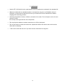
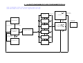
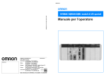
ALLEGATO:DIAGRAMMA DI FLUSSO FUNZIONAMENTO RP1100
* P E R A CC EN DE RE : Pr emer e "ON " fino alla com par sa della scrit ta "ON"
* P E R S P EG NE RE : P r emere " ON" fino alla com par sa della scr it ta "OF F"
(
)
( O N ) breve
S D 1 0/4
(
(
( O N ) pr olu ngato
C AL XXXX
)
S D 5 /4
S P E G NIM E NT O
)
N
C A LIB R A ZIO N E S I
O N ----> NO !
(
FU NZ IO N A M E NTO
N O RM A L E
C O M P A R E LA S C RITTA
"S O N DA " p er un s econ do
circa
(
)
)
A U TO M A TIC O
( )
S D 12 /2.2
(
( O N ) breve
per CO NF E RM A
C A L. S
S D 5 /5
( A CC E NS IO NE )
( ON )
br eve
CO M P A IO NO
LE S C RITTE :
( )
( ON )
breve
( O N ) pr ol ungato
)
S D . ....
(
V E LO CIT A ' m /s
........ .....
( O N ) breve
per conferm a
)
NO
C A LIB R .
....................
IN CO RS O
...................
FA TTO !
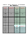
!#"$&%('()*+%
,.-&/102.3&-4&/526&/
7 89: ;;<
= >?@ AB
C D E F G HI J K L M N
O P QR S TU V W X Y
Alluminio
Alluminium
Alpacca
Alpacca
Argento
Silver
Bismuto
6320
4760
3600
2180
2780
5240
5900
3500 ÷ 5800
5770
4660
1450
6800 ÷ 7300
5630
3240
Zinc
Polistirolo
2350
Porcellana
5600 ÷ 6200
Quarzo
5570
Resine epossidiche
Epoxy resins
Teflon
2400 ÷ 2900
1350
Vetro Flint
4260
Vetro Kron
5660
2160
3960
Acqua
1483
Water
4700
Gasolio
1250
Diesel oil
3320
5460
Wolframio
Zinco
2200 ÷ 2600
}~
4400
Platinum
Rame
Copper
Stagno
Tin Pond
Wolframio
Poliammidi
Glass Kron
Lead
Platino
2730
Glass Flint
Brass
Piombo
Plexiglas
Teflon
Gold
Ottone
2200
Quartz
Nichel
Oro
Paraffina solida
China
hard Metal
Nichel
1480
Polistirolo
Mercury
Metallo duro
Gomma tenera
Polyamides
Manganina
Mercurio
2300
Plexiglas
Magnesium
Manganina
Gomma dura
solid Paraffin
Cast iron
Magnesio
3980
tender Rubber
Iron
Ghisa
Ghiaccio
hard Rubber
Costantana
Ferro
9000 ÷ 11000
Ice
Cadmium
Costantana
Allumina
Alluminia
Bismuth
Cadmio
Z [ Z \ ] ^ _ ` ` a j k l m n op q r s t u
b c d e fdg hi
v f hc w xd y z { |
4170
Glicerina
Glycerine
Olio lubrificazione
Lubrication oil
1920
1740