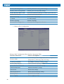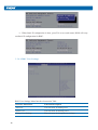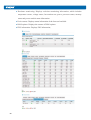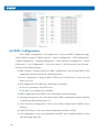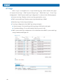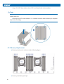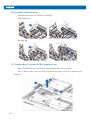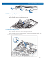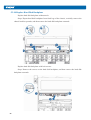
1
Copyright Introduction
Document version: V1.0
Date: 5th Dec. 2014
Document Introduction: The 1st formal issuance.
Abstract
The manual introduces issues closely related to maintenance such as specification, hardware
operation, software configuration, service terms, fault diagnosis etc. of the server.
Readers of this guide will be deemed to have abundant knowledge about the server product,
and will not cause any personal injury or product damage during operation and maintenance, for
sufficient trainings received by them.
Target Audience
This manual mainly adapts to the following personnel:
● Technical support engineers
● Product maintenance engineers
It is suggested that server maintenance operation shall be carried out by professional engineers
with related server knowledge via referring to this manual.
Table of Content
1 SAFETY INTRODUCTION ......................................................................................................
2 PRODUCT SPECIFICATION INTRODUCTION .................................................................
2.1 Introduction .........................................................................................................................
2.2 Features and Specification ..................................................................................................
2.3 Front Panel ..........................................................................................................................
2.4 Rear Panel ...........................................................................................................................
2.5 Mainboard Layout...............................................................................................................
2.6 Mainboard Jumper Introduction .........................................................................................
3 BIOS CONFIGURATION .........................................................................................................
3.1 System BIOS Configuration Methods ................................................................................
3.2 BIOS Configuration ............................................................................................................
3.3Firmware Update .................................................................................................................
4 BMC CONFIGURATION..........................................................................................................
4.1 Introduction .........................................................................................................................
4.2 Functional Modules ............................................................................................................
4.3 Web Interface Introduction .................................................................................................
4.4 Remote Control ...................................................................................................................
4.5 Power Supply and Heat Radiation ......................................................................................
4.6 BMC Configuration ............................................................................................................
4.7 Logs ....................................................................................................................................
4.8 Fault Diagnosis ...................................................................................................................
4.9 System Maintenance ...........................................................................................................
4.10 Command Line Function Introduction .............................................................................
4.11 Time Zone Table ...............................................................................................................
5 HARDWARE MAINTENANC111 ............................................................................................
5.1 Tool Preparation ..................................................................................................................
5.2 Parts Replacement...............................................................................................................
6 FREQUENT FAULTS, DIAGNOSIS AND TROUBLESHOOTING ....................................
6.1 Frequent Faults ...................................................................................................................
6.2 Diagnosis and Exclusion Instructions .................................................................................
7 SPECIFICATIONS .....................................................................................................................
7.1 USA FCC Statement ...........................................................................................................
7.2 CE Statement of EU ............................................................................................................
7.3 China CCC ..........................................................................................................................
7.4 China Environmental Symbols ...........................................................................................
Safety Introduction
1 Safety Introduction
Warning: the following warnings show that there are potential dangers that may cause
property loss, personal injury or death:
1
The power supply equipment in the system may generate high voltage and dangerous
electrical energy and thus cause personal injury. Please do not dismount the cover of
the host or to dismount and replace any component in the system by yourself, unless
otherwise informed by the distributor; only maintenance technicians trained by the
distributor have the right to disassemble the cover of the host, dismount and replace the
internal components.
2
Please connect the equipment to appropriate power supply, and the power should
be supplied by external power supply which is indicated on the rated input label. To
prevent your equipment from damages caused by momentary spike or plunge of the
voltage, please use relevant voltage stabilizing equipment or uninterruptible power
supply equipment.
3
If extended cables are needed, please use the three-core cables matched with correct
earthed plug, and check the ratings of the extended cables to make sure that the sum of
rated current of all products inserted into the extended cables do not exceed 80% of the
limits of the rated currents of the extended cables.
4
Please be sure to use the supplied power supply component, such as power lines, power
socket (if supplied with the equipment) etc. For the safety of equipment and the user, do
not replace randomly power cables or plugs.
5
To prevent electric shock dangers caused by leakage in the system, please make sure
that the power cables of the system and peripheral equipment are correctly connected
to the earthed power socket. Please connect the three-core power line plug to the threecore AC power socket that is well earthed and easy to access, be sure to use the earthing
pin of power lines and do not use the patch plug or the earthing pin unplugged with
cables. In case of the earthing conductors not installed and it is uncertain whether there
are appropriate earthing protections, please do not operate or use the equipment. Contact
and consult with the electrician.
6
To avoid short circuit of internal components and fire or electric shock hazards, please
do not fill any object into the open pores of the system.
1
7
Please place the system far away from the cooling plate and at the place with heat
sources, and be sure not to block the air vents.
8
Be sure not to scatter food or liquid in the system or on other components, and do not
use the product in humid and dusty environment.
9
The replacement of batteries with those of another model may cause explosion. When
replacement of batteries is required, please consult first the manufacturer and choose
batteries of the same or a similar model recommended by the manufacturer. Do not
dismount, extrude and pink the batteries or make the external connection point short
circuit, and do not expose them in the environment over 60°C. Never throw them into
fire or water. Please do not try to open or repair the batteries, and be sure to reasonably
deal with the flat batteries and do not put the fl at batteries, the circuit boards that may
include the batteries and other components with other wastes. For relevant battery
recovery, please contact the local waste recovery and treatment mechanism.
10
Before installing equipment in the chassis, please install front and side supporting feet
on the independent chassis; for cabinet connecting with other chassis, it shall install
the front supporting foot first. If you fail to install correspondingly the supporting foot
before installing equipment in the chassis, it may cause the cabinet to turn over in some
cases, and thus may cause personal injury. Therefore, it is necessary to install supporting
feet before installing equipment in the chassis. After installing the equipment and other
components in the chassis, it can only pull out one component from the cabinet through
its sliding component at one time. Pulling out several components at the same time may
lead the cabinet to turn over and cause serious personal injury.
11
Please do not move the chassis independently. Considering the height and weight of the
chassis, at least two people are needed to complete its movement.
12
Please do not carry out direct contact operation on power copper busbar when the
cabinet is powered on, and it is prohibited to carry out direct short circuit of power
copper busbar.
13
The product is Grade A product, and in the living environment, it may cause radio
interference. In such case, it may need the user to take feasible measures for the
interference.
Note: In order to help you use the equipment, the following considerations can help avoid the
occurrence of problems that may damage the components or cause data loss etc.
2
Safety Introduction
1
In case of the following cases, please unplug the power line plug of products from the
power socket and contact customer service department of the distributor:
1) The power cables, extended cables or power plugs are damaged.
2) The products get wet by water.
3) The products have fallen off or been damaged.
4) Objects fall into the products.
5) When operating according to the operation instructions, the products cannot function
normally.
2
If the system becomes damp, please dispose according to the following steps:
1) Switch off the power supplies of the system and the equipment, disconnect them
with the power socket, wait for 10 to 20 minutes, and then open the cover of the
host.
2) Move the equipment to the ventilation place to dry the system at least for 24 hours
and make sure that the system is fully dried.
3) Close the cover of the host, re-connect the system to the power socket, and then start
the equipment.
4) In case of operation failure or abnormal situation, please contact the distributor and
get technical support.
3
Pay attention to the position of the system cables and power cables, wire them in places
not to be stepped on or knocked down and ensure not to place other objectives on the
cables.
4
Before dismounting the cover of host or contacting the internal components, you shall
cool down the equipment first; to avoid damaging the main-board, please power off the
system and wait for 5 seconds, and then dismount the components from the main-board
or disconnect the connection of peripheral equipment of the system.
5
If there are modulator-demodulator, telecommunication or local area network options in
the equipment, please pay attention to the following matters:
1) In case of thunder and lightning weather, please do not connect or use the
modulator-demodulator. Otherwise, it may be subject to lightning strike.
2) Never connect or use modulator-demodulator in moist environment.
3) Never insert the modulator-demodulator or telephone cables to the socket of
network interface controller (NIC).
4) Before unpacking the product package, contacting or installing internal components
3
or contacting un-insulated cables or jacks of the modulator-demodulator, please
disconnect the modulator-demodulator cables.
6
In order to prevent the electrostatic discharge from damaging the electronic components
in the equipment, please pay attention to the following matters:
1) You shall conduct off the static electricity on the body before dismounting or
contacting any electronic component in the equipment. You can conduct off the
static electricity on the body by contacting the metal earthing objects (such as the
unpainted metal surface on the chassis) to prevent the static electricity on the body
from conducting itself to the sensitive components.
2) For electrostatic sensitive components not ready to be installed for application,
please do not take them out from the antistatic package materials.
3) During the work, please touch the earthing conductor or the unpainted metal surface
on the cabinet regularly to conduct off the static electricity on the body that may
damage the internal components.
7
When dismounting the internal components with the approval of distributor, please pay
attention to the following matters:
1) Switch off the system power supply and disconnect the cables, including
disconnecting any connection of the system. When disconnecting the cables, please
grab the connector of cables and plug it out, and never pull the cables.
2) Before dismounting the cover of cabinet or touching the internal components, the
products need to be cooled down.
3) Before dismounting and touching any electronic component in the equipment,
you shall conduct off the static electricity on the body by touching the metal
earthingobjectives.
4) During the dismounting process, the operation shall not be too big, so as to prevent
damage to the components or scratching of the arms.
5) Carefully deal with the components and plug-in cards, and please never touch, the
components or connection points on the plug-in cards. When taking the plug-in
cards or components, you should grab the edges of the plug-in cards or components
or their metal fixed supports.
8
During the process of cabinet installation and application, please pay attention to the
following matters:
1) After the installation of cabinet is finished, please ensure that the supporting feet
4
Safety Introduction
have been fixed to the rack and supported to the ground, and all weight of the rack
have been fell onto the ground.
2) It shall install into the cabinet according to the sequences from the bottom to the top,
and first install the heaviest component.
3) When pulling out the components from the cabinet, it shall apply force slightly to
ensure the cabinet to keep balance and stabilization.
4) When pressing down the release latch of the sliding rail of components and sliding
in or out, please be careful, as the sliding rail may hurt your figures.
5) Never make the AC power branch circuit in the cabinet overload. The sum of cabinet
load shall not exceed 80% of the ratings of branch circuits.
6) Ensure that components in the cabinet have good ventilation.
7) When repairing components in the cabinet, never step on any other components.
5
2. Product Specification Introduction
2.1 Introduction
This type is a kind of server product developed independently. It adopts Intel GrantleyEP platform, and uses Wellsburg chip set. It supports two mainstream Intel Xeon E5-26**
V3 series processors. It supports 16 DIMM DDR4 memory, up to 2133MHz. It supports
ECC Registered and multiple senior memory redundancy functions. It supports up to 2.5”
x8 SAS/SATA/SSD hot-plugging hard disks or 3.5” x4 SAS/SATA/SSD hot-plugging hard
disks + 2.5” x2 SSD hot-plugging hard disks. Mainboard integrates a Gigabit net card of high
performance, and supports network advanced features. Mainboard integrates BMC/KVM
chips. 2 PCI-Express expansion slots are available.
Supports SAS 3.0 (12Gb/s) or SAS Raid cards, and implements flexible SAS/SAS
RAID solutions. Modular design on components such as structure, storage, PCI expansion,
power supply and fan etc. Energy-saving and noise reduction design, equipped with PMbus
power supply of high efficiency, supports DPNM function, and implements energy saving
and consumption reducing.
●
2.5”×8 configuration (i.e. full configuration)
It supports 8 front set 2.5” SAS/SATA/SSD hard disks, and the related appearance is as
shown in the following figure.
●
3.5”×4 configuration (i.e. full configuration)
It supports 4 front set 3.5”/2.5” SAS/SATA/SSD hard disks and 2 2.5” SSD hard disks,
while the related appearance is as shown in the following figure.
6
Product Specification Introduction
Note: 3.5” hard disk bracket could hold 3.5”/2.5” hard disks.
2.2 Features and Specification
Processor
Processor Type
Intel dual-way Xeon E5-26XX V3 Series (supports up to two 145W)
Interface
Two Socket-R3 slots.
Chipset
Chipset Type
PCH C610(Wellsburg)
Memory
Memory Type
DDR4 ECC RDIMM/LRDIMM memory
Single Inline Memory
16
Module Qty.
Memory Volume
It supports up to 1024GB (64GB for single)
I/O Interface
USB Interface
2 front set USB 3.0 interfaces, 2 built-in USB 3.0 interfaces, and 2 rear
set USB 3.0 interfaces.
Display Interface
1 front set VGA interface
1 rear set VGA interface
Serial Interface
1 built-in serial port
ID Indicator Interface
1 ID indicator (blue) and its press button
Display Controller
Controller Type
Aspeed 2400
7
SAS Backplane
SAS3.0 backplane
3.5x4 backplane: The backplane supports 3.5"x4 hard disks, and SAS
backplane provides 1 HD Mini SAS interface, 1 8PIN power interfaces;
1 2.5x2 backplane is installed:
The backplane supports 2.5"x2 hard disks, and the backplane provides 2
SATA interfaces and 1 4PIN power interfaces; while 1 2.5x8 backplane
is installed:
The backplane supports 2.5"x2 hard disks, and SAS backplane provides
2 HD Mini SAS interfaces and 1 8PIN power interfaces; while 1 is installed
Network Card
The mainboard is optionally integrated with 1 Intel I350 dual or four
Gigabit net card, providing two or four 1000M adaptive RJ45 network
Network Card
ports;
Controller
The mainboard is optionally integrated with 1 Intel 82599 single-port or
dual-port net card, providing one or two 10 gigabit SFP+ network ports.
Management Chip
Management Chip
It integrates 1 independent 1000Mbps network interface, which is used
in IPMI remote management.
Mainboard:
1 onboard PCI Express 3.0 x24 slot (used to support PCI-E Riser, which
could not adapt to external cards); 3 vertically inserted PCIE slots;
PCI Extension Slot
In the system:
Single CPU: It could support 1 PCIE x8+x1 slot (able to support
network sub card of management function), which transfers via a halfheight and half-length PCI-E Riser card.
Dual CPUs:
Could support 1 PCIE x8+x1 slot (able to support network sub card
of management function), which transfers via PCI-E Riser card, and
supports half-height and half-length cards.
Could support 1 PCIE x16 slot (x16 signal), which transfers via
installing one Riser card, and supports full-height and half-length cards.
Hard Disk
Hard Drive Type
Front set 2.5/3.5 inch SAS and SATA hard disks; Up to 2 front set SSD
hard disks could be supported. (Subject to actual type you purchased)
External Storage Driver
8
CD Driver
It supports Slim SATA interface DVD drive (9.5 mm)
External USB CD drive.
Drive U Disk
Optional drive U disk.
Product Specification Introduction
Power Supply
Specification
Output power of sing/double power 550W/800W and above; 1+1
redundancy; 2 power modules; it supports PMBus power supply, and
implements Node Manager 3.0 function.
Power Input
Please refer to power input on nameplate tag of the host.
Physical Specification
External Dimension
635 width × 215 height × 955 depth (unit: mm)
of Package
Host Size
430 width × 44 height × 730 depth (unit: mm)
Product Weight
Gross weight: 26kg. (Gross weight includes: Host + Packing Box + Rail
+ Parts Kit)
Environment Parameters
Working Environment
10℃ -35℃
Temperature
Storage &
Transportation
Temperature
-40℃ -55℃
Working Humidity
35% -80% relative humidity
Storage &
Transportation
Humidity
20% -93% (40℃ )relative humidity
2.3 Front Panel
2.3.1 2.5×8 Disk Position
No.
Module Name
1
Securing buckle of server and cabinet
2
Front set VGA interface
3
Front set USB 3.0 interface
4
Server switch button
5
ID light and button
6
See Section 2.3.3 item 4-9.
7
Hard disk slot
9
2.5×8 disk position hard disk sequence diagram
2.3.2 3.5×4 Disk Position
No.
Module Name
1
Securing buckle of server and cabinet
2
CD Driver
3
Front set VGA interface
4
Front set USB 3.0 interface
5
Server switch button
6
ID light and button
7
See Section 2.3.3 item 4-9.
8
2.5 inches SSD hard disk slot
9
3.5 inches hard disk slot
3.5×8 disk position hard disk sequence diagram
2.3.3 Front Control Panel Buttons and Indicators
10
Product Specification Introduction
No.
Module Name
1
USB interface
2
Server switch button
3
ID light and button
4
Network status indicator
5
Memory fault indicator
6
Power fault indicator
7
System overheating indicator
8
Fan fault indicator
9
System fault indicator
2.3.4 Indicators on Hard Disk Bracket
Number
Module Name
Description
1
Hard disk activity
status indicator
Constant green: Normal
Flashing green: Hard disk is reading and writing
2
Hard disk fault
alarming indicator
Constant red: Hard disk fault
Constant blue: Hard disk positioning
Constant blue: In coordination with RAID rebuilding
2.4 Rear Panel
11
No.
Module Name
1
PSU0
2
PSU1
3
PCIE x8 slots
4
PCIE x16 slots
5
IPMI management ports
6
USB 3.0 ports (2)
7
VGA port
8
Gigabit network port
9
ID light and button
10
BMC Reset Button
11
10 Gigabit net card indicator
12
10 Gigabit net card
2.5 Mainboard Layout
12
Product Specification Introduction
No.
Module Name
1
Memory slot (corresponding with CPU0)
2
CPU0
3
Memory slot (corresponding with CPU1)
4
CPU1
5
GPU Power supply interface
6
System fan interfaces (8 interfaces in all)
7
I2C interface
8
GPIO interface
9
IPMB interface
10
SATA interfaces (6)
11
CLEAR CMOS jumper
12
TCM interface
13
COM interface
14
sSATA interfaces (4)
15
Front set USB 3.0 interface
16
Built-in USB 3.0 interface
17
Front set VGA interface
18
IPMI management interface / rear set USB 3.0 interface (2)
19
PCIEx24 slots (corresponding with CPU1)
20
Rear set VGA interface
21
Debug light
22
Gigabit network port
23
ID light and button
24
BMC Reset button
25
10 Gigabit net port
26
PCIEx16 slots (corresponding with CPU1)
27
PCIEx8 (corresponding with CPU0)
28
PCIEx8 (in x16 slots corresponding with CPU0)
29
Mainboard handle
30
PSU1
31
PSU0
32
Power interface (4 ports)
33
Power interface (8 ports)
34
Front control panel interface
35
LSI 3008 HD mini SAS interface
36
LSI 3008 SAS Key
13
2.6 Mainboard Jumper Introduction
2.6.1 Clear CMOS Jumper Introduction
See [2.5 Mainboard Layout] for jumper positions.
Jumper No.
Function Description
Jumper Functions
CLR_CMOS
CMOS clear jumper
J46 Short-circuit pin1-2, to restore normal status;
short-circuit pin2-3, to clear CMOS.
It is required to shut down the system, as well as disconnect power supply during CMOS
cleaning, and hold for 5 seconds after short-circuiting Pin2-3; then short-circuit Pin1 and Pin2 of
CLR_CMOS jumper with a jumper cap (the default status), to restore its original status.
14
Product Specification Introduction
3 BIOS Configuration
This chapter introduces BIOS function setup and mainboard jumper of the server. All
operations described in this section are only limited to operators or administrators with
system maintenance qualification.
BIOS is a basic input and output system. The system parameter and the hard drive
parameter can be adjusted through special set program. BIOS has great influence on the
system start and running so that setting parameters improperly may arose the conflict among
the hardware resource, or fall down the system run performance. Hence understanding the
BIOS setup is significant to the configuration of your server. If no especial requirement, you
are suggested to use the default value and not alter the parameters optionally.
1. Before the server BIOS setup is altered, please record the corresponding original setup.
Hence when there are operating problems in the system due to the option altered, the setup can
revert.
2. Ordinarily the factory default system value is the optimized setup. Don’t try to alter the
parameters before you understand their denotations.
3. The common setup is introduced in detail in this paper. The less referred options in the
application procedure are simply explained or not.
4. The content of the BIOS is diverse based on the different configurations of the products;
hence the detailed introduction is elided.
3.1 System BIOS Configuration Methods
Power on the server, system starts to boot, when the following content appears below
the distributor logo on the screen:
“Press <DEL> to SETUP or <TAB> to POST or <F12> to PXE Boot.”, press [DEL]
button, when “Entering Setup...” appears on bottom right on the screen, it will enter system
BIOS configuration later, and you could select options using arrow buttons on BIOS main
menu to enter sub-menu.
Note: Options in grey are not available. Options with symbol“
”, have a sub-menu.
15
Control key instruction table
Press Key
Function
<Esc>
Exit or return from sub-menu to main menu.
<←>or<→>
Select a menu.
<↑>or<↓>
Move the cursor up or down.
<Home>or<End>
Move the cursor to top or bottom of the screen.
<+>or<->
Select the previous or next numerical value or setting of the current one.
<F1>
Help
<F2>
Restore the last configuration.
<F9>
Restore default configuration.
<F10>
Save and exit
<Enter>
execute commands or select a sub-menu.
3.2 BIOS Configuration
3.2.1 Main Menu
Main Menu Interface Instruction Table
16
Interface Parameters
Function Description
BIOS Information
Displays current BIOS information.
Processor Information
Displays CPU information.
Memory Information
Displays memory volume and current speed.
System Date(Day mm/dd/yyyy)
System Time (hh/mm/ss)
Displays system time.
Access Level
Current access level
Product Specification Introduction
3.2.2 Advanced Menu
Advanced Menu Interface Instruction Table
Interface Parameters
Function Description
Trusted Computing
Trustable computing configuration
ACPI Settings
Advanced configuration and power interface settings
AST2400 Super IO Configuration
AST2400 I/O chip parameter configuration
Serial Port Console Redirection
Serial port console redirection settings
PCI Subsystem Settings
PCI subsystem settings
Network Stack Configuration
Network stack configuration
CSM Configuration
CMS configuration
USB Configuration
USB configuration
Onboard LAN Configuration
Onboard network card configuration
3.2.2.1 Trusted Computing
Trusted Computing Menu Interface Instruction Table
Interface Parameters
Function Description
Security Device Support
BIOS’s security device support settings
Current Status Information
Status information of the current security device
17
3.2.2.2 ACPI Settings
Advanced Menu Interface Instruction Table
Interface Parameters
Function Description
Enable ACPI Auto Configuration
To allow ACPI’s automatic configuration.
Lock Legacy Resources
The locking legacy resources setting
3.2.2.3 AST2400 Super IO Configuration
AST2400 Super IO Configuration Menu Interface Instruction Table
18
Interface Parameters
Function Description
Super IO Chip
The current I/0 chip
Serial Port 1 Configuration
Serial port 1 configuration
Product Specification Introduction
3.2.2.4 Serial Port Console Redirection
Serial Port Console Redirection Menu Interface Instruction Table
Interface Parameters
Function Description
Console Redirection
The console redirection switching settings
Console Redirection Settings
The console redirection parameter settings
3.2.2.4.1 Console Redirection Settings
When the Console Redirection option is set to [Enabled], the Console Redirection
Settings menu is started.
19
Console Redirection Settings Menu Interface Introduction
Interface Parameters
Function Description
Terminal Type
Terminal type settings
Bits per second
Baud rate settings
Data Bits
Data bits settings
Parity
Parity check settings
Stop Bits
Stop bits settings
Flow Control
Flow control settings
VT-UTF8 Combo Key Support
VT-UTF8 Combo key support settings
Recorder Mode
Recorder mode settings
Redirection 100×31
Expanded terminal resolution settings
Legacy OS Redirection Resolution
Terminal resolution settings of legacy OS
Putty KeyPad
Putty’s functional keys and keyboard settings
Redirection After BIOS POST
Redirection after BIOS bootup settings
3.2.2.5 PCI Subsystem Settings
PCI Subsystem Settings Menu Interface Instruction Table
20
Interface Parameters
Function Description
PCI Latency Timer
PCI delay timer settings
PCI-X Latency Timer
PCI-X delay timer settings
VGA Palette Snoop
VGA color correction settings
Above 4G Decoding
64bit equipment’s decoding settings on address space
larger than 4G.
Product Specification Introduction
3.2.2.6 CSM Configuration
CSM Configuration Menu Interface Instruction Table
Interface Parameters
Function Description
CSM Support
CSM support settings
GateA20 Active
A20 address line’s control mode settings
Option Rom Message
Option Rom display mode settings
Boot option filter
Boot option filter settings
Option ROM execution
Option Rom execution method
Network
Network card Option Rom execution method settings
Storage
Storage device Option Rom execution method settings
Video
Video device Option Rom execution method settings
Other PCI devices
Other PCI devices Option Rom execution method settings
3.2.2.7 USB Configuration
21
USB Menu Interface Instruction Table
Interface Parameters
Function Description
Legacy USB Support
Legacy USB device settings
XHCI Hand-off
Expansible host controller interface settings, orienting to
USB 3.0.
EHCI Hand-off
Enhanced host controller interface settings, orienting to
USB2.0.
USB Mass Storage Driver Support
USB mass storage driver support settings
Port 60/64 Emulation
USB port 60/64h emulation settings
3.2.2.8 Onboard LAN Configuration
Onboard LAN Configuration Menu Interface Instruction Table
22
Interface Parameters
Function Description
Onbaord I350 NIC1 Control
Onboard network card NIC1 switching settings
Onbaord NIC2 Control
Onboard network card NIC2 switching settings
Onboard NIC1 ROM
Onboard network card NIC1 PXE Oprom switching settings
Onboard NIC2 ROM
Onboard network card NIC2 PXE Oprom switching settings
Product Specification Introduction
3.2.3 Chipset Menu
Chipset Menu Interface Instruction Table
Interface Parameters
Function Description
Processor Configuration
Processor configuration
Advanced Power Management Configuration
Advanced power management configuration
QPI Configuration
QPI configuration
Memory Configuration
Memory configuration
IIO Configuration
IIO configuration
PCH Configuration
PCH configuration
Server ME Configuration
Server ME configuration
Runtime Error Logging
Runtime error log configuration
Common Configuration
Common options configuration
3.2.3.1 Processor Configuration
23
Processor Configuration Menu Interface Instruction Table
Interface Parameters
Function Description
Hyper Threading Technology
Processor information sub-menu, and processor detailed
information.
Hyper threading technology settings
Core Enabled
CPU core number settings
Execute Disable Bit
Virus protecting technology settings
Intel TXT Support
Intel trustable execution technology support settings
VMX
Intel hardware-assisted virtualization technology settings
SMX
Safe mode expansion settings
Hardware Prefetcher
Hardware prefetch settings
Adjacent Cache Prefetch
Adjacent high speed cache prefetch settings
DCU Streamer Prefetcher
DCU Streamer prefetch settings
DCU IP Prefectcher
DCU IP prefetch settings
Direct Cache Access (DCA)
Direct high speed cache access settings
AES-NI
Intel AES-NI advanced encryption standard settings
Processor Information
3.2.3.2 Advanced Power Management Configuration
Advanced Power Management Configuration Menu Interface Instruction Table
Interface Parameters
Function Description
Power Technology
To set power management
CPU P State Control
CPU C State Control
24
CPU P State control sets sub-menu, and starts when
Power Technology is set to [Custom].
CPU C State control sets sub-menu, and starts when
Power Technology is set to [Custom].
Energy Performance Tunning
CPU performance and energy tuning sub-menu
Socket RAPL Configuration
Turbo power limit settings sub-menu, and EIST option
requires to be set to [Enabled].
DRAM RAPL Configuration
DRAM RAPL configuration sub-menu
Product Specification Introduction
1)CPU P State Control
CPU P State Control Menu Interface Instruction Table
Interface Parameters
Function Description
EIST(P-states)
EIST switching settings
Turbo Mode
Turbo mode switching settings
2)CPU C State Control
CPU C State Control Menu Interface Instruction Table
Interface Parameters
Function Description
Package C State limit
C state limit settings
CPU C3 report
C3 switching settings
CPU C6 report
C6 switching settings
Enhanced Halt State (C1E)
C1E switching settings
25
3)Energy Performance Tuning
Energy Performance Tunning Menu Interface Instruction Table
Interface Parameters
Function Description
Energy Performance Tunning
To select BIOS or OS to carry out energy performance tuning
Energy Performance BIAS
Energy performance management settings
Workload Configuration
Workload configuration
Force
3.2.3.3 QPI Configuration
26
Product Specification Introduction
QPI Configuration Menu Interface Instruction Table
Interface Parameters
Function Description
QPI Satus
QPI status display sub-menu
Degrade Precedence
To degrade to priority settings.
Link Speed Mode
Link speed mode settings
Link Frequency Select
Link frequency selection settings
Link L0p Enable
Link power saving mode settings, which is made when
bandwidth is half of the peak bandwidth..
Link L1 Enable
In the case that system is extremely idle, turn off QPI Link.
E2E Parity Enable
E2E parity check enabling settings
COD Enable
COD enabling settings
Early Snoop
Early Snoop settings
3.2.3.4 Memory Configuration
Memory Configuration Menu Interface Instruction Table
Interface Parameters
Function Description
Enforce POR
To execute POR settings
Memory Frequency
Memory frequency settings
ECC Support
ECC support settings
Rank Multiplication
Rank multiplication settings
LRDIMM Module Delay
LRDIMM module delay settings
Data Scrambling
Data scrambling settings
Refresh Options
Refresh mode settings
Command/Address Parity
DDR4 command/address parity check settings
27
Memory Throttling Mode
Memory thermal throttling mode settings
Memory Power Savings Mode
Memory power saving mode settings
Socket Interleave Below 4GB
Processor Interleaving settings on address space below 4G.
Channel Interleaving
Channel interleaving settings
Rank Interleaving
Rank interleaving settings
A7 Mode
A7 mode settings
Memory Topology
Memory Topology
Memory RAS Configuration
Memory RAS configuration sub-menu
1)Memory RAS Configuration
Memory RAS Configuration Menu Interface Instruction Table
28
Interface Parameters
Function Description
Memory Mode
As for memory mode configuration, there’re 3 options of
[Independent], [Mirroring] and [Lock Step].
Lockstep X4 DIMMs
X4 DIMMs’ Lockstep switching settings
Memory Rank Sparing
Memory Rank hot sparing settings
Correctable Error Threshold
Correctable error threshold settings
DRAM Maintenance
DRAM maintenance settings
Patrol Scrub
Patrol Scrub settings
Patrol Scrub Interval
Patrol Scrub interleaving settings
Demand Scrub
Demand Scrub settings
Device Tagging
Device tagging settings
Product Specification Introduction
3.2.3.5 IIO Configuration
IIO Configuration Menu Interface Instruction Table
Interface Parameters
Function Description
IIO0 Configuration
IIO0 configuration sub-menu, used to set link speed of
PCIE device of CPU0.
IIO1 Configuration
IIO1 configuration sub-menu, used to set link speed of
PCIE device of CPU1.
I/OAT Configuration
Intel I/O acceleration technology configuration sub-menu.
Intel VT for Directed I/O (VT-d)
Intel VT-d switching settings
3.2.3.6 PCH Configuration
29
PCH Configuration Menu Interface Instruction Table
Interface Parameters
Function Description
Chassis Intrusion
Chassis intrusion switching settings
Restore AC Power Loss
AC power-on power status settings
PCH sSATA Configuration
PCH sSATA configuration sub-menu
PCH SATA Configuration
PCH SATA configuration sub-menu
USB Configuration
USB configuration sub-menu
1)PCH SATA Configuration
Taking PCH SATA Configuration menu as an example, introduce onboard SATA port,
and SATA hard disk configuration, while PCH Ssata Configuration is similar to this, which
will not be repeated here.
PCH SATA Configuration Menu Interface Instruction Table
Interface Parameters
Function Description
SATA Controller
SATA controller switching settings
Configure SATA as
As for SATA mode configuration, there’re two modes of [AHCI] and
[RAID] for setting.
SATA Port 0/1/2/3/4/5
Information of hard disks connected to onboard SATA port
0/1/2/3/4/5.
SATA RAID mode configuration.
a、Configure SATA as an option set to [RAID], press F10 to save settings, and system
restarts.
b、During system startup, the following content will display on the screen:
30
Product Specification Introduction
Press<CTRL-I> to enter Configuration Utility…
Meanwhile, press [Ctrl] and [I] synchronously to enter SATA RAID configuration
interface, and one example is as shown in the following figure.
c、After entering SATA RAID configuration interface, menu list information,
information of hard disk connecting to SATA controller (hard disk ID number, hard disk type,
hard disk capacity as well as whether hard disk is a volume member etc.), existed RAID
volume information (including volume ID number, name, RAID level, capacity, status,
whether information bootable) will all display.
Press Key
Description
↑↓
Used to move cursor in different menus or to change values of menu options.
TAB
To select the next menu setting option.
Enter
To select a menu.
Esc
To exit menu or return to previous menu from sub-menu.
d、SATA RAID configuration interface has the following 4 executable menus:
Create RAID Volume
To create an RAID volume.
Delete RAID Volume
To delete an existed RAID volume.
To reset hard disks in RAID volume, and to restore them to
non-RAID status.
To exit SATA Host RAID configuration interface.
Reset Disks to Non-RAID
Exit
31
a)Create RAID Volume Menu
After entering SATA RAID configuration interface, you could use up and down arrows
to select this menu, then press [Enter] to create an RAID volume menu, or directly enter the
number before the menu to create an RAID volume menu, for other menu operations are
similar, so it will not be repeated here. A Create RAID Volume instance is as shown in the
following figure:
System displays the following menu options:
Name
Please enter a volume label name less than 16 characters without containing any
special character.
RAID Level
Please select RAID volume level, if no volume has been created at
present, there’re four volume levels of RAID0(Stripe), RAID1(Mirror),
RAID10(RAID0+1) and RAID5(Parity)for selection, please select volume level
according to actual requirements.
RAID0: This RAID volume is allowed to be made on 2 or above hard disks.
RAID1: This RAID volume is allowed to be made on 2 hard disks.
RAID10: This RAID volume is allowed to be made on 4 hard disks, which is
only available when hard disk quantity is 4 or above.
RAID5 (Parity): This RAID volume is allowed to be made on 3 or above hard
disks.
Disks
Select hard disks to make RAID volume, press enter after this option is selected,
system will enter hard disk selection interface, please select hard disks to make
RAID volume using space key accordingly, and then press enter to return to
volume create menu.
Strip Size
Please select strip size, only RAID0 and RAID5 volumes could select this option.
Capacity
Set volume capacity, and the default value is the max. volume capacity.
After completing the above configuration, please select [Create Volume], and press
enter, system prompts: “WARNING:ALL DATA ON THE SELECTED DISKS WILL BE
32
Product Specification Introduction
LOST. Are you sure you want to create this volume ?(Y/N):”.
To create an RAID volume, please enter “Y”, a volume will be created, and all data on
the selected disk will be lost.
Otherwise, please enter “N”, to exit volume creation.
Here we enter “Y” to create an RAID volume, after creation completed, return to SATA
Host RAID configuration main interface, and the created RAID volume will display in RAID
volume.
b)Delete RAID Volume Menu
After entering Delete RAID Volume menu, system prompts: “Deleting a volume will
reset the disks to non-RAID. Warning:ALL DISKS DATA WILL BE DELETED.”.
To delete an RAID volume, please press [DEL], system prompts: “ALL DATA IN THE
VOLUME WILL BE LOST!” again. Are you sure you want to delete “Volume*”?(Y/N):”, to
delete this RAID volume, please enter “Y”, to cancel deletion of this RAID volume, please
enter “N”.
c)Reset Disks to Non-RAID Menu
33
After entering Reset Disks to Non-RAID menu, system will display all hard disks in
RAID volume, please select the hard disk to reset using the space key according to actual
demand, and then press enter to reset the hard disk, system prompts “Are you sure you want
to reset RAID data on selected disks? (Y/N)” again, enter “Y” or “N” according to prompt.
It is to be noted that, during resetting hard disk, data on this disk will all be lost, meanwhile,
this disk will not belong to RAID volume any more.
d)Exit Menu
System prompts:”Are you sure you want to exit?(Y/N):”, enter “Y”, to exit SAS RAID
configuration interface, enter “N”, to cancel exit operation.
3.2.3.7 Server ME Configuration
34
Product Specification Introduction
Server ME Configuration Menu Interface Instruction Table
Interface Parameters
Function Description
Operational Firmware Version
Operational ME firmware version
Recovery Firmware Version
Recovery ME firmware version
ME Firmware Features
ME firmware features
ME Firmware Status #1
ME FW status value #1
ME Firmware Status #2
ME FW status value #2
Current State
Current state
Error code
ME FW error code
3.2.3.8 Common Configuration
Common Configuration Menu Interface Instruction Table
Interface Parameters
Function Description
MMCFG Base
MMCFG base address settings
Isoc Mode
Isoc mode settings
MeSeg Mode
MeSeg mode settings
Numa
Numa switching settings
BIOS Guard
BIOS guarding settings
VGA Priority
Integrated video card and external video card priority settings.
35
3.2.4 Server Mgmt
Server Mgmt Menu Interface Instruction Table
36
Interface Parameters
Function Description
BMC Firmware Version
BMC firmware version
FRB-2 TImer
FRB-2 clock settings
FRB-2 Timer timeout
FRB-2 clock expiration time settings
FRB-2 Timer policy
Policy settings after FRB-2 clock expiration
OS Watchdog Timer
System watchdog clock settings
OS Wtd Timer timeout
OS watchdog clock expiration time settings
OS Wtd Timer policy
Policy settings after OS watchdog clock expiration
BMC network configuration
BMC network settings
System Event Log
System event log sub-menu
View FRU information
To view FRU information sub-menu.
BMC network configuration
BMC network configuration sub-menu
BMC User Settings
BMC user settings sub-menu
SystemHealth Information
System health information sub-menu
Product Specification Introduction
3.2.4.1 System Event Log
System Event log Menu Interface Instruction Table
Interface Parameters
Function Description
SEL Components
System event log switching settings during startup
Erase SEL
System event log erasing settings
When SEL is Full
Operation settings after system event log is full.
Log EFI Staus Codes
Logging EFI status codes settings
3.2.4.2 View FRU Information
The View FRU Information menu lists BMC FRU information read by BIOS, and
BIOS will interact with BMC at each system restart, keeping synchronous update of FRU
information.
37
3.2.4.3 BMC network configuration
、
BMC network configuration Menu Interface Instruction Table
Interface Parameters
Function Description
Configuration Address Source
Configuration BMC Network Status Parameter: It
could set static IPs, and obtain IPs dynamically, while
[Unspecified] will not modify BMC network parameters.
Current Configuration Address
Current configuration address status
Station IP adderess
Port IP address
Subnet mask
Subnet mask
Station MAC address
Port MAC address
Router IP address
Router IP address
Router MAC address
Router MAC address
BMC network configuration on BIOS setup interface, is to configure BMC management
network via BIOS.
1)If no operation is carried out in BIOS, by default, it will read BMC, and configure its
Dedicated management port and shareline management port, taking Dedicated management
port as an example, the BIOS reading configuration is as shown in the following figure:
38
Product Specification Introduction
2)BIOS could carry out Dynamic and Static network settings on BMC Dedicated
management port and sharelink management port, taking Dedicated management port as an
example, to set a BMC Static IP as follows:
a、Set the Configuration Address Source option to [Static]
b、Set the Configuration Address Source option to [Static]
c、Select the Station IP Address option, and press Enter, to pop up the Station IP
Address window, enter the Static IP to set manually, after configuration is completed, press
Enter to confirm, and an example is as shown in the following figure:
c、Select the Subnet Mask option, and press Enter, to pop up the Subnet Mask box,
enter the Subnet Mask to set manually, after configuration is completed, press Enter to
confirm, and an example is as shown in the following figure:
d、Select the Router IP Address option, and press Enter, to pop up the Router IP
Address box, enter the Router IP Address to set manually, after configuration is completed,
press Enter to confirm, and an example is as shown in the following figure:
39
e、When Static IP configuration is done, press F10 to save and restart, BIOS will carry
out Static IP configuration for BMC.
3.2.4.4 BMC User Settings
BMC User Settings Menu Interface Instruction Table
40
Interface Parameters
Function Description
Add User
The sub-menu for adding users.
Delete User
The sub-menu for deleting users.
Change User Settings
The sub-menu for changing user settings.
Product Specification Introduction
1)Add User operation
a、Select the User Name option, and press Enter to pop up the User Name box, enter
the user name to set manually, after configuration is completed, press Enter to confirm.
b、Select the User Password option, and press Enter to pop up the User Password box,
enter the user password to set manually, after configuration is completed, press Enter to
confirm.
c、Channel NO is set to 1 or 8.
d、The User Privilege Limit option, sets privilege for new user, after configuration
is completed, press Enter, to pop up the BMC USER SETTINGS INFO box, when system
prompts “Set User Access Command Passed”, press Enter and then OK to confirm, the new
user is added successfully, and the example is as shown in the following figure:
41
2)Delete User operation
a、Select the User Name option, and press Enter to pop up the User Name box,
manually enter the user name to delete, after configuration is completed, press Enter to
confirm.
b、Select the User Password option, and press Enter to pop up the User Password box,
manually enter the user password to delete, after that, press Enter to confirm, and the BMC
USER SETTINGS INFO prompt will pop up, indicating user password deletion is done or
not.
3)Change User Settings
42
Product Specification Introduction
a、Select the User Name option, and press Enter to pop up the User Name box,
manually enter the user name to modify, after configuration is completed, press Enter to
confirm.
b、Select the User Password option, and press Enter to pop up the User Password box,
manually enter the user password, and press Enter to confirm.
c、Select the User option, and set to [Enable] or [Disable].
d、Select the Change User Password option, to change user password.
e、Channel No. is set to 1 or 8.
f、The User Privilege Limit option, could change user’s privilege, after configuration is
completed, press Enter, to pop up the BMC USER SETTINGS INFO prompt, when system
prompts “Set User Access Command Passed”, press Enter and then OK to confirm, the user
settings information is changed successfully.
3.2.4.5 System Health Information
System Health Information Menu Interface Instruction Table
Interface Parameters
Function Description
System Temperature Information
System temperature information sub-menu
System Fan Speed
System fan speed sub-menu
System Voltage Information
System voltage information sub-menu
43
1)System Temperature Information
2)System Fan Speed
3)System Voltage Information
44
Product Specification Introduction
3.2.5 Security Menu
Security Menu Interface Instruction Table
Interface Parameters
Function Description
Administrator Password
Create a password for administrator.
User Password
Create a password for normal user.
3.2.6 Boot Menu
45
Boot configuration Menu Interface Instruction Table
Interface Parameters
Function Description
Bootup NumLock State
Numlock keys status settings after bootup.
Boot Options Retry
The booting device polling settings
Quiet Boot
To boot quietly, set this option to Enabled, and boot logo
displays as that set by manufacturer, disabled, boot logo
displays as AMI’s default logo.
Boot Option Priorities
Boot Option #X
Hard Driver BBS Priorities
Network Device BBS Priorities
Boot option priority settings
Hard disk device BBS priority settings
Network device BBS priority settings
To set BIOS boot operation:
Enter Boot menu, move the cursor to Boot option #X via up and down arrows to select,
and set system boot sequence, with X set to 1, 2, 3 etc., while an example is as shown in the
following figure:
Taking Boot option #1 as an example, you could set the first boot device for the system:
Move the cursor to Boot option #1, and press Enter, to pop up the boot option for selection:
i.e. IBA GE slot 0400 v1543, UEFI: Built-in EFI Shell, UEFI:USB2.O DISK 1100, USB2.O
DISK 1100 etc., select one via up and down keys, i.e. USB2.O DISK 1100, and press Enter,
to select USB DOS disk as the first boot device for the system.
46
Product Specification Introduction
3.2.7 Save & Exit Menu
Save & Exit Menu Menu Interface Instruction Table
Interface Parameters
Function Description
Save Changes and Exit
To Save and exit
Discard Changes and Exit
To abandon changes and exit.
Save Changes and Reset
To save changes and reboot
Discard Changes and Reset
To abandon changes and reboot
Save Changes
To save changes.
Discard Changes
To abandon changes.
Restore Defaults
To restore factory settings.
Save as user Defaults
To save as defaults.
Restore user Defaults
To restore user defaults.
Boot Override
To reload boot device, you could select all boot devices
in the following.
3.3 Firmware Update
For BIOS update, you could select to update in DOS or OS.
1)Use afudos tool to update BIOS in DOS
System boots from USB DOS startup disk, enters the directory containing afudos tool,
while bin files of the corresponding new BIOS version have been put into this folder, execute
command: afudos BIOS.bin /b /p /n /x /me to update BIOS and ME, for BIOS.bin – bin files
of the new BIOS version, an example is as shown in the following figure:
47
When there’s no change in ME part, to update BIOS part, it is only required to execute
command: afudos BIOS.bin /b /p /n /x.
Parameter instructions: /b -- Program Boot Block
/p -- Program Main BIOS
/n -- Program NVRAM
/x -- Don’t Check ROM ID
/me -- Program ME Entire Firmware Block
2)Use afudos tool to update BIOS in Linux OS
There’re 32bit and 64bit Linux OS afulnx tools, taking Linux 64bit OS as an example,
use afulnx_64 tool, to enter the directory containing afulnx_64 tool, meanwhile, put bin files
of corresponding BIOS into this folder, and enter command: /afulnx_64 BIOS.BIN /P /B /N /
X /R, while an example is as shown in the following figure:
When there’s any change in ME part, to update BIOS part, it is required to execute
command: afudos BIOS.bin /b /p /n /x /me, with parameter instructions identical to DOS.
3)Use afuWin tool to update BIOS in Windows OS
48
Product Specification Introduction
There’re 32bit and 64bit Windows OS afuwin tools, and afuwinx64.exe is used in 64bit
OS, run a command prompt, to enter the directory containing afuwinx64.exe tool, meanwhile,
put bin files of corresponding BIOS into this folder, and enter command: afuwinx64.exe
BIOS.BIN /P /B /N /X /R, to update BIOS files.
Meanwhile, GUI method is provided in Windows to refresh BIOS. Taking Windows
2008R2 OS as an example, use AFUWINGUI tool to update BIOS.
a、Run AUWINGUI.EXE tool, as shown in the following figure:
b、Click the Open button, after selecting the BIOS.bin file to update, system enters
Setup interface automatically.
49
c、Select Program all Blocks and Do Not Check ROM ID options on Setup interface,
click flash button, system enters Progress interface automatically, and executes BIOS update
accordingly according to colors shown on the right, thus BIOS update is done as shown in
the following figure:
50
Product Specification Introduction
4 BMC Configuration
4.1 Introduction
This chapter introduces specifications and main functions to be abided by management
software.
the distributor server management software is a control unit realizing server
management, which is compatible with management standard of the server industry IPMI2.0
specification.
It mainly realizes the following functions:
● Remote control:
It realizes server control via functions such as KVM (Keyboard Video and Mouse), SOL
(Serial Over Lan) and virtual media etc.
Note: SOL function has to be realized via third party tools such as IPMITool etc.
● Alarming management
Reports alarming information in a real-time way, and carries out corresponding solutions
according to information.
● Status monitoring
Monitors various running states of all monitoring units in a real-time way.
● Device information management
Provides device version information, type and asset information.
● Heat radiation control
It could adjust fan rotation rate according to ambient temperature and workload
dynamically.
● Supports IPMITool tool management.
Supports operation according to commands sent by IPMITool, and you could download
IPMITool by yourself.
Note: IPMITool downloading website:http://ipmitool.sourceforge.net/manpage.html
● Supports WEB interface management
Provides a friendly and visual interface management, and you could complete tasks of
configuration and query via a click on the interface quickly.
51
● Supports account centralized management
Supports to store accounts in Active Directory server, and direct certification to server,
so as to realize management system login with domain accounts.
4.2 Functional Modules
This chapter introduces the distributor server management system module composition
as well as functions of these modules.
4.2.1 Module Composition
The distributor server management system is mainly composed of IPMI module,
command line module, WEB module, KVMOver IP and virtual media etc.
● Command module realizes the calling of IPMI module. User realizes the operation on
IPMI module via command lines.
● WEB module realizes daily management on server in the form of visual interface via
calling IPMI commands, and WEB module has integrated functions of KVM and virtual
media.
4.2.2 IPMI Module Introduction
IPMI module realizes management on server system according to IPMI2.0 standard.
Functions realized by IPMI module include:
● System real-time monitoring
It could realize alarming report, alarming indication and self-protection of startup
system, when there’s any fault detected.
● System remote control
It could realize management requirements such as remote power-on/off, and business
system reset etc. via command lines and Web.
4.2.3 Command Line Function Introduction
Command line module includes query and configuration commands for network, sensor,
fan, user management, system and server etc.
52
Product Specification Introduction
4.2.4 Remote Control Module Introduction
Remote control module includes:
● KVM Over IP: It means a management method that user carries out monitoring and
control on remote devices via using local video, keyboard and mouse at client, to
operate remote devices in a real-time way.
● Virtual media: A method of providing remote access on local media (CD-Rom, floppy
drive or CD/floppy disk iso file) in the form of virtual CD driver and floppy drive on
server via internet.
Instructions:
If Java runtime environment does not comply with requirements, user could login
http://www.oracle.com/technetwork/java/javase/downloads/index.html to download.
4.3 Web Interface Introduction
About this chapter
It introduces Web interface of management system as well as operation steps to login
Web interface.
● Login Web interface.
Introduces methods to login Web interface.
● Web interface introduction
Introduces Web interface layout.
4.3.1 Login Web Interface
It introduces methods to login Web interface.
This guide introduces operation steps to login Web management interface, taking
Windows 7 operation system and FireFox browser as examples.
Note: When carrying out interface operation via Web, up to 20 users could login
synchronously.
Step 1 Ensure management net ports on Client and server are connected to internet.
Step 2 Open the browser, and enter “http://ipaddress” in the address bar. (In which
ipaddress is the IP address of management port, for specific determining method on IP
address, please refer to the annex to determine IP address of management network port)
53
Step 3 The login interface pops up, as shown in the following figure, in this interface:
1. Enter user name and password.
Note: System provides a default user “admin” in administer user group, and the default
password is “admin”.
2. Click “Login”, to enter the management interface.
4.3.2 Web Interface Introduction
The Web interface helps users to accomplish server management via its visual
and friendly interface, and the Web interface contains online help, so users could query
instructions and operation guide on this interface via clicking button
on any interface.
Web interface is divided into four parts, as shown in the following figure.
● The name of Web interface is displayed on top left of the interface.
● Meanings of all buttons on top right of the interface:
Click the System Abstract button, to return to the System Abstract page.
Click the Refresh button, to refresh the page.
Click the Language button, to shift language, which supports Chinese and English.
Click the Help button to query help information on corresponding page.
Click the Logout button, to return to login page.
● There’s a navigation tree on the left, via nodes on the tree, you could select different
54
Product Specification Introduction
functional interfaces. Functions able to be realized via Web interface include: Viewing
the overall situation, viewing system information, remote control, power management,
event and log query, real-time monitoring, diagnosis and orientation, system
maintenance, and system configuration etc. For detailed introduction on all functions,
please refer to the following chapters.
● Specific operation interface is on the right of the interface.
4.3.3 Overall Situation
Click System Abstract, to open the “System Abstract” interface, as shown in the
following figure.
4.3.4 System Information
Select “System Information” on navigation tree, which includes five interfaces of “Asset
Information”, “Hardware Monitoring”, “Device Status”, “BIOS Option”, “FRU Information”,
as shown in the following figure.
● Asset information: Displays system configuration information, which includes CPU,
memory, PCIE device and Mac address information.
55
● Hardware monitoring: Displays real-time monitoring information, which includes
temperature sensor, voltage sensor, fan rotation rate, power, processor status, memory
status and power module status information.
● Device status: Displays status information of the front set hard disk.
● BIOS options: Displays the setstate of BIOS options.
● FRU information: Displays FRU information;
56
Product Specification Introduction
4.4 Remote Control
Select “Remote Control” on navigation tree, to open the remote control interface, which
contains six interfaces of “Console Redirection (KVM)”, server switch-on/off control, server
orientation, remote session configuration, virtual media configuration and mouse mode
configuration, as shown in the following figure.
● Console redirection (KVM): To pop up the KVM console window.
● Server switch-on/off control: To control startup, shutdown and restart of the server.
● Server orientation: To turn on/off the positioning light.
● Remote session configuration: To set KVM session encryption, media encryption
and virtual media connection methods.
● Virtual media configuration: To set the quantity of virtual media (floppy disks, CD
drives and hard disks etc.)
● Mouse mode configuration: To set the mouse working mode for KVM remote
console.
57
58
Product Specification Introduction
4.5 Power Supply and Heat Radiation
Select “Power Supply and Heat Radiation” on navigation tree, to open the power supply
and heat radiation page, which contains three pages of power supply monitoring, power
supply management, fan rotation rate control, as shown in the following figure.
● Power supply monitoring: Contains power supply module presence status, alarming
status, temperature, input power, output power, input voltage, output voltage, input
current, output current and power supply module firmware version information.
● Power supply management: Contains power supply module presence status, current
status and primary/secondary mode switching function.
● Fan rotation rate control: Contains fan status, current rotation rate information and
rotation rate control function.
Note: Fan rotation rate control contains the following rotation rate gears:
★ Low speed gear: About 20% duty ratio.
★ Medium speed gear: About 50% duty ratio.
★ High speed gear: About 80% duty ratio.
★ Full speed gear: 100% duty ratio.
59
4.6 BMC Configuration
Select “BMC Configuration” on navigation tree, to open the BMC configuration page,
which contains 10 pages of “BMC Network”, “Service Configuration”, “NTP Configuration”,
“SMTP Configuration”, “Alarming Management”, “Active Directory Configuration”, “LDAP/
E-Directory”, “User Configuration”, “IP Access Control”, “NCSI Network Card Selection”,
as shown in the following figure.
● BMC network: Contains network for BMC configuration (static IP and DHCP), DNS
configuration and network interface binding function.
● Service configuration: Configures BMC’S Web service, KVM service, ssh service and
telnet service etc.
● NTP configuration: Sets BMC time, which has two methods:
★ One is to synchronize from NTP server.
★ The other is to configure time manually.
● SMTP configuration: Sets SMTP server information related to alarming.
● Alarming management: Sets information about BMC management module alarming
event filtering and alarming targets etc.
● Active directory configuration: Carries out related configuration on BMC active
directory.
● LDAP/E-Directory: Carries out related configuration on BMC’s LDAP.
● User configuration: Carries out management on BMC users, including add user, delete
user and change password.
60
Product Specification Introduction
● IP access control: Configures IP address fields accessible to BMC.
● NCSI network card selection: Includes NCSI network card switching, and NCSI work
mode switching functions.
61
62
Product Specification Introduction
63
4.7 Logs
Select “Logs” on navigation tree, to open related log page, which contains four pages
of “System Event Logs”, “BMC System Design Logs”, “Black Box Logs”, “Event Logs
Configuration”, “BMC System Audit Logs Configuration”, as shown in the following figures.
● System event logs: Displays various event logs generated by server.
● BMC system audit logs: Displays system logs and audit logs of BMC.
● Black box logs: Used to import fault logs.
● Event logs configuration: Sets BMC logs storage strategies:
★ Linear strategy: To clean all logs after log storage is full and record again.
★ Circulation strategy: To record circularly after log record is full.
● BMC system audit logs configuration: Sets information about BMC system audit logs
storage methods and lengths etc.
64
Product Specification Introduction
4.8 Fault Diagnosis
Select “Fault Diagnosis” on navigation tree, to open fault diagnosis page, which
contains three pages of “Task Restart”, “Last Crash Screen” and “System Power On Self test
codes”. As shown in the following figure.
● Task restart: Contains restart two functions of restarting BMC and restarting KVM
service;
● Last crash screen: Used to capture information on the last screen at system crash;
Note: Blue screen only adapts to Windows 2008R2 and Windows 2012 OS;
● System power on self test codes: Displays power-on codes during system startup.
65
4.9 System Maintenance
Select “System Maintenance” on navigation tree, to open system maintenance page,
which contains four pages of “BMC Firmware Update”, “BIOS Firmware Update”, “Restore
Factory Configuration” and “System Administrator”. As shown in the following figures.
● BMC firmware update: Carries out update on BMC FW via BMC Web interface;
● BIOS firmware update: Carries out update on BIOS via BMC Web interface;
● Restore factory configuration: Restores BMC’s configuration to factory state.
● System administrator: Displays the information of system administrator.
66
Product Specification Introduction
4.10 Command Line Function Introduction
About this chapter
It introduces Web interface of management system as well as operation steps to login
Web interface.
67
● Login command line
Introduces methods of login command line.
● Command line function introduction
Introduces command line functions.
4.10.1 Command line login:
Command line using ssh to login BMC, default user name: root, and default password:
rootuser.
After login, you could enter the command line interface:
Enter help, you could view online help:
4.10.2 Command Line Function Introduction
4.10.2.1 Network Information Acquisition and Configuration:
You could acquire and configure BMC’s network information via ipconfig instruction:
68
Product Specification Introduction
4.10.2.2 Sensor Information Acquisition:
Via sensor instruction, you could acquire all sensor information lists:
4.10.2.3 FRU Information Acquisition and Configuration:
Via FRU instruction, you could acquire FRU configuration information:
4.10.2.4 Chassis Status Acquisition and Control:
Via chassis instruction, you could acquire and control system power status.
69
Acquiring system power status:
4.10.2.5 User Acquisition, Adding and Deleting:
Via user instruction, you could acquire the user list, to add or delete users.
Acquiring user list:
4.10.2.6 BMC Version Acquisition and BMC Restart
Via mc instruction, you could acquire BMC version information, and restart BMC.
Acquiring BMC version information:
70
Product Specification Introduction
4.10.2.7 Fan Work Mode Configuration and Fan Rotation Rate Acquisition:
Via fan instruction, you could either set fan work mode, or acquire fan rotation rate.
Fan rotation rate acquisition:
4.10.2.8 Power Module Information Acquisition and Configuration:
Via Psu instruction, you could either acquire power module information, or set power
module as main output.
Power module information acquisition:
71
4.10.2.9 Change Root Password:
Via password instruction, you could change root user’s password:
4.11 Time Zone Table
72
Time Zone
Countries and Regions
GMT-12:00
West Date Line
GMT-11:00
Appiah, Niue, Pago Pago, Midway
GMT-10:00
Fakaofo, Rarotonga, the island of Tahiti, Johnston, Hawaii
GMT-09:30
Marquesas
GMT-09:00
Alaska, Gambier Islands
GMT-08:00
Pacific Time (USA and Canada), Pitcairn, Whitehorse, Tijuana, Vancouver
GMT-07:00
Mountain Time (USA and Canada), Edmonton, Hermosillo, the Tao gave birth
to Crick, Chihuahua, Yellowknife, Arizona, Mazatlan
GMT-06:00
Central Time (USA and Canada), Belize, Costa Rica, Easter Island, Galapagos
Islands, Salvatore, Guatemala, Managua, Mexico City, Regina, Winnipeg
GMT-05:00
Eastern Time (USA and Canada), Panama, Bogota, Toronto, Grand Turk Island,
Montreal, Iqaluit, Guayaquil, Havana, the Cayman Islands, Leo Brown Cu,
Lima, Nassau, Port au Prince, Jamaica
GMT-04:00
Atlantic Time (Canada), Aruba, Anguilla, Antigua, Babado J, Bermuda, Puerto
Rico, Bo Avesta, Campo Grande, Halifax City, Dominica, Grenada, Guadeloupe,
Guyana, Caracas, Curacao, Cuiaba, Labasse, Martinique, Manaus, Montserrat,
Palmer, Santiago, Santo Domingo, St. Kitts, St Lucia, St. Thomas, Vincent,
STANLEY, Thule, Tortora, Porto Velho, port of Spain, Asuncion
GMT-03:30
St. Louis
GMT-03:00
Aragua ina, Belem, Buenos Aires, Fortaleza, Geert Holob, cayenne, Recife,
Lutheran, Maceio, Montevideo, Miquelon Island, Paramaribo, Salvatore, St.
Paul
GMT-02:00
South Georgia, Noronha
GMT-01:00
Cape Verde, Si kolle SBI Sander, Azores
GMT+00:00
Abidjan, Accra, Bamako, Banjul, Laayoune, Bissau, Dakar, Dublin, Freetown,
Greenland, the Canary Islands, Casablanca, Conakry, Reykjavik, Lisbon,
London, Monrovia, Nouakchott, Saint Lome, how beautiful, St. Helena,
Ouagadougou
Product Specification Introduction
GMT+01:00
Algiers, Amsterdam, Andorra, Oslo, Paris, Berlin, Bangui, Porto Novo,
Budapest, Brazzaville, Brussels, Tirana, Douala, Ndjamena, Copenhagen,
Warsaw, Kinshasa, Lagos, Liebe Weil, Luxemburg, Luanda, Rome, Madrid,
Malta, Monaco, Niamey, Stockholm, Guinea, Zurich, Tunisia, Vaduz, Vienna,
Windhoek, Ceuta, Gibraltar
GMT+02:00
Amman, Beirut, Bucharest, Blantyre, Bujumbura, Damascus, Tripoli, Harare,
Habo Roney, Helsinki, Kiev, Kigali, Kihine U, Cairo, Gaza, Riga, Lubumbashi,
Lusaka, Maputo, Minsk, Kaliningrad, Maseru, Mbabane, Nicosia, Sofia, Tallinn,
Tel Aviv, Vilnius, Athens, Istanbul, Johannesburg
GMT+03:00
Antananarivo, Baghdad, Bahrain, Dar Es Salaam, Djibouti, Qatar, ha Khartoum,
Kampala, Comoros, Kuwait, Mayotte, Riyadh, Mogadishu, Moscow, Nairobi,
Addisababa, Aden, Showa
GMT+03:30
Newfoundland
GMT+04:00
Baku, Dubai, Tbilisi, Reunion Island, Mahe, Muscat, Mauritius, Samarra, Ye
Liewan
GMT+04:30
Kabul
GMT+05:00
Aktau Aktobe, Ashkhabad, Karachi, Dushanbe, Kell islands, Maldives, Kelang,
Yekaterinburg, Tashkent
GMT+05:30
Colombo, India
GMT+06:00
Ala Mutu, Bishkek, Chagos, Dhaka, Mo Sen, Omsk, Novosibirsk, Thimphu,
Vostok
GMT+06:30
The Coco Islands, Yangon
GMT+07:00
Davies, Hanoi, Phnom Penh, Khovd, Bangkok, Lasinuoyaersike, Christmas
Island, Vientiane, Jakarta
GMT+08:00
Macao, Kuala Lumpur, Manila, Ilkuts J, Casey, Macassar, Taipei, Brunei, Ulan
Bator, Perth, Singapore, Beijing, Hongkong, China
GMT+09:00
Chaya Pla, Dili, Tokyo, Yakutsk, Palau, Pyongyang, Qiao Bashan, Seoul
GMT+09:30
Adelaide, Darwin
GMT+10:00
Di Mundi Weil, Brisbane, Hobart, Melbourne, Sydney, Guam, Port Moresby,
Yuzhno-Sakhalinsk, Saipan, Truc
GMT+11:00
Efate, Ponape Island, Guadalcanal, Kosrae, Magadan, Noumea
GMT+11:30
Nuo Fuke
GMT+12:00
Oakland, Funafuti, Kwajalein, Majuro, Pietro Pavlov's Kamchatka, Tarawa
Island, Wallis, Wake Island, Nauru, Fiji
GMT+13:00
Nukualofa
73
5 Hardware Maintenance
5.1 Tool Preparation
● Tools to be prepared before construction, as shown in the following table.
Tool List
Illustration
Name
Description
Phillips
Screwdriver
Used to fix bolts.
Anti-static
Wrist Strap
Used to contact or operate
devices and apparatuses, to
prevent static electricity.
Anti-static
Gloves
Used to plug in single
board, hand-held single
board or other precision
instruments etc., to prevent
static electricity.
5.2 Parts Replacement
Special tips: Except hot plugging parts (i.e. hot plugging hard disk etc.), all part
replacements could only be carried out with power disconnected.
5.2.1 Processor Replacement
During installing and replacing CPU, please pay attention to the following issues:
● During installing two CPUs, type of these two CPUs shall be the same.
● When only one CPU is to be installed, please operate according to the following
requirements:
1)This CPU has to be installed on CPU0’s socket, and see [Mainboard Diagram] for
CPU position.
74
Product Specification Introduction
2)It is not allowed to dismantle the protective cover on sockets without CPU1
installed.
Step 1: Open two pull rods on CPU slot, and open CPU fixing plate.
Step 2: Install CPU into CPU slot, and then remove protective cover on CPU slot.
Step 3: Clamp CPU with CPU fixing plate, and then fix two pull rods firmly.
75
Step 4: Fix CPU heat radiator above CPU, and fasten bolts on heat radiator.
● It is required to coat thermal grease evenly onto contact position between CPU heat
radiator and CPU.
● During fixing CPU heat radiator, it is required to fasten bolts according to diagonal
sequence accordingly.
5.2.2 Memory Replacement
● Memory slot layout is as shown in the following figure:
● Memory installation principle:
76
Product Specification Introduction
Only memory of the same type could be used in the same machine. Detailed memory
installation and combination principles are as follows:
a、The white slot shall take the priority, while CPU1 memory shall be symmetrically
installed with CPU0.
b、For single CPU, memory shall follow the screen printing sequence: CHA-0, CHB-0,
CHC-0, CHD-0, CHA-1…
c、For dual CPUs, CPU0 position memory shall follow the screen printing sequence:
CHA-0, CHB-0, CHC-0, CHD-0, CHA-1… CHG-0, CHH-0, CHE-0, CHF-0 …
Step 1: Open fixing catches on both ends of memory slot.
Step 2: Align the notch at memory bottom with memory slot positioning point, and press
both ends of the memory with your thumbs, to insert the memory into the slot completely,
and then fasten fixing catches on both ends of the memory slot.
5.2.3 Hard Disk Replacement
Step 1: Press hard disk panel button.
77
Step 2: Pop up buckles on hard disk bracket automatically, flatten and dismantle hard
disk bracket.
Step 3: Use four hard disk bolts to fix the hard disk onto the bracket.
Step 4: Install the hard disk into the server, and fasten hard disk buckles firmly.
5.2.4 Power Replacement
Step 1: Pull power catch in the direction of the arrow.
78
Product Specification Introduction
Step 2: Remove the power horizontally with even force.
Step 3: Install power module.
Push the new power module into the sliding channel, until a “click” sound is heard,
power spring leaf is caught into the buckle automatically, and power module could not move
any more.
5.2.5 Chassis Cover Replacement
Step 1: Press the two lock catches on the chassis cover, and push them horizontally to
the rear of the chassis, to make the chassis rear cover leave the front window cover about
1cm.
Step 2: Vertically remove the chassis cover upwards.
79
5.2.6 System Fan Replacement
Hold both ends of the fan, and lift up vertically.
Non-hot plug fan:
Hot-plug fan:
5.2.7 Replace Riser Card and PCIE Expansion Card
Step1: Hold the two holes on the Riser card, uplift the Riser card vertically.
Step 2: Remove the screws on PCIE expansion card, take out PCIE expansion card
outwards.
80
Product Specification Introduction
5.2.8 Wind Scooper Replacement
Step 1: Open upper cover of the chassis.
Step 2: Vertically remove the wind scooper upwards.
5.2.9 Mainboard Replacement
Step 1: Dismantle all parts and cables connecting to mainboard.
Step 2: Dismantle 10 screws on the mainboard, lift mainboard ring-shaped handle, and
vertically remove the mainboard upwards.
81
5.2.10 Replace Hard Disk Backplane
Replace hard disk backplane without tools:
Steps: Depart hard disk backplane from fixed legs of the chassis, vertically remove the
chassis buckles upwards, and then remove the hard disk backplane outwards.
Replace hard disk backplane with lock screws:
Steps: Remove the screws on the hard disk backplane, and then remove the hard disk
backplane outwards.
82
Frequent Faults, Diagnosis and Troubleshooting
6. Frequent Faults, Diagnosis and Troubleshooting
This chapter introduces
Frequent server faults as well as corresponding diagnosis and troubleshooting
suggestions.
6.1 Frequent Faults
1) No power after startup
After the machine is connected with power cable, no power is provided for the
machine while pressing the On/Off button, and indicator does not light up after
power on.
2) Power module indicator off or red indicator on
The machine is under normal operation, but a certain power module indicator is off
or red indicator is on to alarm.
3) No display after power on
No information output appeared on the display after power on via pressing On/Off
button.
4) Front panel indicator is off
All front panel indicators are off after power on.
5) Front panel status indicator alarms
The machine is under normal operation, but status indicator alarms.
6) Blank screen of the display
Blank screen fault occurs during display usage.
7) Abnormal display
Trembling, rolling or twisting screen images on the display during machine usage.
8) Memory capacity displays abnormality
It is shown by the operation system that memory capacity does not correspond with
physical memory capacity.
9) Keyboard and mouse are not available
Neither keyboard nor mouse could be operated normally.
10) USB interface problem
Introduces solutions to failing to use USB interface.
83
6.2 Diagnosis and Exclusion Instructions
1) Diagnosis and exclusion on power-on failure at startup
Description: After pressing the power button, server front control panel indicator
(power-on status indicator, hard disk status indicator) is off, meanwhile, no KVM
(display) output is displayed, and server chassis fan does not rotate.
Operation steps:
a、Verify whether machine power supply is normal or not: If power module
indicator is on, it indicates normal power supply; if power module indicator is
off, please check if power supply is normal;
b、If power supply is normal, plug in and off the power module again to test, and
then start for verification;
c、If there’s a machine and a power module of the same type, you could change the
power module to test whether there’s a power module fault;
d、If no solution could be achieved via the above operation, please contact the
distributor customer service.
2) Power module indicator off or red indicator on
Description: The machine is under normal operation, but a certain power module
indicator is off or the red light is on.
Operation steps:
a、Firstly check whether all power cables are normal, and plug in power cables again;
b、If fault still exists, plug in and off power module again;
c、If shutdown is allowed, you could exchange these 2 power modules, to judge
whether it is a power module fault.
d、If no solution could be achieved via the above operation, please contact the
distributor customer service.
3) No display if power on
Description: After pressing the power button, server front control panel indicator is
on, but there’s no output on the display.
Operation steps:
a、Firstly check whether VGA port on display and server is connected normally;
84
Frequent Faults, Diagnosis and Troubleshooting
b、Test on another display
d、If no solution could be achieved via the above operation, please contact the
distributor customer service.
4) Front panel status indicator alarms
Description: The server is under normal operation, but system status indicator on
front control panel flashes or the red indicator is on to alarm.
Operation steps:
Please check whether all power module indicators are green constant, if so, you
could login BMC web interface to collect logs, and contact the distributor customer
service.
5) Memory capacity incomplete
Description: Memory capacity viewed via the operation system does not correspond
with physical memory capacity.
Operation steps:
a、Ensure all memories have been correctly installed in place, and memories of
correct type have also been configured.
b、Enter BIOS setup to view memory capacity, if it could be completely identified
in BIOS setup, this may lie in the limitation on memory capacity set by the
operation system. Otherwise, please contact the distributor customer service.
6) Keyboard and mouse are not available
Description: Neither keyboard nor mouse could be operated normally.
Operation steps:
a、Make sure whether cable connection of keyboard or mouse is correct and firm.
b、Test other parts to verify whether it is a mouse or keyboard fault.
c、Retest the machine via power on/off.
d、Reboot and enter cmos or raid configuration interface to test keyboard or
mouse performance, when tested in a non-system situation, if keyboard or
mouse performance turns out to be normal, a system fault could be considered;
if keyboard or mouse fault still exists, a mainboard interface fault could be
considered, and you could contact the distributor technical support.
85
7) USB interface problem
Description: Unable to use devices with a USB interface.
Operation steps:
a、Make sure operation system on server supports USB devices.
b、Make sure system has been installed with correct USB device driver.
c、Power off the server, and then power on again to test.
d、Make sure whether the USB device is normal when connecting to other hosts.
e、If the USB device is normal when connecting to other hosts, the server may be
abnormal, please contact the distributor technical support; if the USB device
turns out to be abnormal when connecting to other hosts, change the USB device.
86
Specifications
7 Specifications
This chapter introduces various access authentications achieved by this
product and standards it complies with.
● USA FCC statement.
Introduces FCC standards abided by the product.
● CE statement of EU.
Introduces CE standards abided by the product.
● China CCC
Introduces CCC standards abided by the product.
● China Environmental Symbols
Introduces China environmental symbols standards abided by the product.
7.1 USA FCC Statement
Introduces FCC standards abided by the product.
It is regulated in Subpart B, Part 15 of 47 CFR by Federal Communications Commission
of the United States that users of this product shall pay attention to the following issues:
Annotations: This device has been tested and complies with regulations related to Class
A digital devices in Part 15 of FCC rules. Main purpose of these limitations is to provide
reasonable protection while operating such devices in business districts, to avoid harmful
disturbance. This device may produce, use and emit RF energy, if installation or usage
is carried out not according to instructions, harmful disturbance may be caused on radio
communication. Operating this device in residential areas may cause harmful disturbance, in
this case, the user will be responsible for all costs arisen from correcting disturbance.
If the user carries out change or correction not expressly indicated by our company, it
may cause the device failing to comply with FCC Class A requirements, and exempted from
its authorization to operate this device.
7.2 CE Statement of EU
This chapter introduces CE standards abided by this product.
This is a Class A product. In the dwelling environment, this product may cause radio
disturbance, in this case, the user will be asked to adopt certain appropriate measures.
7.3 China CCC
This chapter introduces the CCC standards to be abided by the product.
87
This product is a class A product, in daily life, it may cause radio disturbance, in this
case, it is required to adopt practicable precautions against its disturbance.
7.4 China Environmental Symbols
The products comply with China environmental symbols criteria.
Name of Hazardous Substances or Elements in the Product & Content Mark Table – Server
Part Name
Toxic and Harmful Substances or Elements
Pb
Hg
Cd
Cr(VI)
PBB
PBDE
Case
×
○
○
○
○
○
Mainboard
×
○
○
○
○
○
Memory
○
○
○
○
○
○
Hard Disk
○
○
○
○
○
○
Power Supply
×
○
○
○
○
○
Cable
○
○
○
○
○
○
Floppy drive
×
○
○
○
○
○
CD Drive
×
○
○
○
○
○
External Plug-in Net Card
×
○
○
○
○
○
External Plug-in Storage Card
○
○
○
○
○
○
Connection Plate Card
×
○
○
○
○
○
Data Cable
×
○
○
○
○
○
Keyboard
×
○
○
○
○
○
Mouse
×
○
○
○
○
○
Central Processor
×
○
○
○
○
○
Processor Radiator
×
○
○
○
○
○
Rail
○
○
○
○
○
○
Printing
○
○
○
○
○
○
CD
○
○
○
○
○
○
Package
○
○
○
○
○
○
Packing Pads
○
○
○
○
○
○
Packing Plastic Bags
○
○
○
○
○
○
Instructions:
1. ○: Indicates content of hazardous substances in all homogenous materials of this part is below limit
regulated in Requirements for Concentration Limits for Certain Hazardous Substances in Electronic
Information Products.
2. ×: Indicates content of hazardous substances in at least one homogenous material of this part is below
limit regulated in Requirements for Concentration Limits for Certain Hazardous Substances in Electronic
Information Products. In the table, “×” indicates printed board welding technique limit fails to reach limit
requirements.
3. All the above parts are possible configuration parts in product, for actual product configuration please
refer to configuration label.
88