1
UEFI Development PC
Setup User Manual
Document Revision 1.03
June 4, 2012
Public Document (PUB)
Copyright 2011 American Megatrends, Inc.
5555 Oakbrook Parkway, Suite 200, Norcross, Georgia 30093,
U.S.A.
All Rights Reserved
Property of American Megatrends, Inc.
UEFI Development PC
Setup User Manual
Legal
Disclaimer
This publication contains proprietary information which is protected by copyright. No part of this publication may
be reproduced, transcribed, stored in a retrieval system, translated into any language or computer language, or
transmitted in any form whatsoever without the prior written consent of the publisher, American Megatrends, Inc.
American Megatrends, Inc. retains the right to update, change, modify this publication at any time, without notice.
For Additional Information
Call American Megatrends, Inc. at 1-800-828-9264 for additional information.
Limitations of Liability
In no event shall American Megatrends be held liable for any loss, expenses, or damages of any kind whatsoever,
whether direct, indirect, incidental, or consequential, arising from the design or use of this product or the support
materials provided with the product.
Limited Warranty
No warranties are made, either expressed or implied, with regard to the contents of this work, its merchantability,
or fitness for a particular use. American Megatrends assumes no responsibility for errors and omissions or for the
uses made of the material contained herein or reader decisions based on such use.
Trademark and Copyright Acknowledgments
Copyright ©2012 American Megatrends, Inc. All Rights Reserved.
American Megatrends, Inc.
5555 Oakbrook Parkway
Suite 200
Norcross, GA 30093 (USA)
Copyright © 2012 American Megatrends Inc. ● Public Document (PUB)
Page 2 of 28
UEFI Development PC
Setup User Manual
Table of Contents
Chapter 1
Main Setup ...................................................................................................................... 5
Chapter 2
Advanced Configuration................................................................................................ 7
Network Stack ...................................................................................................................................... 7
Boot Feature ........................................................................................................................................ 7
Power Configuration ............................................................................................................................ 8
Processor & Clock Options .................................................................................................................. 9
Turbo Boost Technology (Available when lntel® EIST technology is Enabled) ................................... 10
Chipset Configuration ........................................................................................................................ 11
CPU Bridge Configuration .................................................................................................................. 11
South Bridge Configuration ................................................................................................................ 13
IDE/SATA Configuration .................................................................................................................... 14
PCle/PCI/PnP Configuration .............................................................................................................. 15
Super IO Device Configuration........................................................................................................... 16
Hardware Health Configuration .......................................................................................................... 16
ACPI Configuration ............................................................................................................................ 17
Trusted Computing Configuration ...................................................................................................... 18
lnteI® TXT (LT) Configuration ............................................................................................................ 19
AMT Configuration ............................................................................................................................. 19
Chapter 3
Security Settings .......................................................................................................... 20
Secure Boot Policy............................................................................................................................. 21
Chapter 4
Boot Settings................................................................................................................ 22
Boot Options Priority .......................................................................................................................... 23
Delete Boot Option............................................................................................................................. 23
Chapter 5
Exit Options .................................................................................................................. 24
Appendix
Copyright © 2012 American Megatrends Inc. ● Public Document (PUB)
Page 3 of 28
UEFI Development PC
Setup User Manual
Date
Rev
Description
Dec 15, 2011
1.00
Initial Internal Release
Dec 19, 2011
1.01
Added overview, introduction and installation
sections
Jan 26, 2012
1.02
Added graphics and appendix
Jun 4, 2012
1.03
Edited sections
Copyright © 2012 American Megatrends Inc. ● Public Document (PUB)
Page 4 of 28
UEFI Development PC
Setup User Manual
Chapter 1
Main Setup
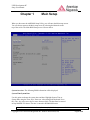
When you first enter the AMI BIOS Setup Utility, you will enter the Main setup screen.
You can always return to the Main setup screen by selecting the Main tab on the
top of the screen. The Main BIOS Setup screen is shown below.
System Overview: The following BIOS information will be displayed:
System Time/System Date
Use this option to change the system time and date. Highlight System Time or
System Date using the arrow keys. Enter new values through the keyboard. Press
the <Tab> key or the arrow keys to move between fields. The date must be entered
in Day MM/DD/YY format. The time is entered in HH:MM:SS format.
Note: The time is in 24-hour format, For example, 5:30 P.M. appears as 17:30:00
Copyright © 2012 American Megatrends Inc. ● Public Document (PUB)
Page 5 of 28
UEFI Development PC
Setup User Manual
The following BIOS items will also be displayed:
Supermicro C7Q67
Version
Build Date
Processor
The AMI BIOS will automatically display the status of the processor used in the motherboard as shown below:
Type of Processor
Speed
Physical Count
Logical Count
System Memory
This displays the size of memory available in the system: -
Size
Copyright © 2012 American Megatrends Inc. ● Public Document (PUB)
Page 6 of 28
UEFI Development PC
Setup User Manual
Chapter 2
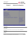
Advanced Configuration
Use the arrow keys to select Boot Setup and press <Enter> to access the submenu items:
Network Stack
Network Stack
Use this feature to enable or disable the network stack. The options are Enable, and Disable Link
Boot Feature
Quiet Boot
Copyright © 2012 American Megatrends Inc. ● Public Document (PUB)
Page 7 of 28
UEFI Development PC
Setup User Manual
Use this feature to select the screen display between POST messages or the OEM
logo at bootup. Select Disabled to display the POST messages. Select Enabled
to display the OEM logo instead of the normal POST messages. The options are
Enabled and Disabled.
CSM Support
Use this feature to set the compatibility Option ROM. The options are Enabled, and Disabled. Disabled is the
default option..
AddOn ROM Display Mode
Use this feature to set the display mode for Option ROM. The options are Force
BIOS and Keep Current.
Bootup Num-Lock
This feature selects the Power-on state for the Numlock key. The options are Off and On.
Wait For ‘F1’ if Error
This forces the system to wait until the ‘F1’ key is pressed if an error occurs. The options are Disabled and
Enabled.
Interrupt 19 Capture
Interrupt 19 is the software interrupt that handles the boot disk function. When this item is set to enabled, the ROM
BIOS of the host adaptors will "capture" interrupt 19 at bootup and allow the drives that are attached to these host
adaptors to function as bootable disks. If this item is set to Disabled, the ROM BIOS of the host adaptors will not
capture Interrupt 19, and the drives attached to these adaptors will not function as bootable devices. The options
are Enabled and Disabled.
Power Configuration
Power Button Function
This feature controls how the system shuts down when the power button is pressed. Select 4_Seconds_Override for
the user to power off the system after pressing and holding the power button for 4 seconds or longer. Select instant
Off to instantly power off the system as soon as the user presses the power button. The options are 4 Second
Override and Instant Off.
Restore on AC Power Loss
Use this feature to set the power state after a power outage. Select Power-Off for the system power to remain off
after a power loss. Select Power-On for the system power to be turned on after a power loss.
Copyright © 2012 American Megatrends Inc. ● Public Document (PUB)
Page 8 of 28
UEFI Development PC
Setup User Manual
Select Last State to allow the system to resume its’ last power state before a power lost. The options are
Power-On, Power-Off and Last State.
Processor & Clock Options
Warning! Take Caution when changing the Advanced settings. An incorrect
value, a very high DRAM frequency or an incorrect DRAM timing setting may cause system to become
unstable. When this occurs, revert to the setting to its manufacture default setting.
Clock Spread Spectrum
If set to Auto, the system will configure with optimal settings. The options are Disabled and Enabled.
Hardware Prefetcher (Available when supported by the CPU)
If set to Enabled, the hardware prefetcher will prefetch streams of data and instructions from the main memory to
the L2 cache to improve CPU performance. The options are Disabled and Enabled.
Adjacent Cache Line Prefetch (Available when supported by’ the CPU)
Select Enabled for the CPU to prefetch both cache lines for 128 bytes as comprised. Select Disabled for the CPU to
prefetch both cache lines for 64 bytes. The options are Disabled and Enabled.
lntel® Virtualization Technology (Available when supported by the CPU)
Select Enabled to use the lntel Virtualization Technology to allow one platform to run multiple operating systems
and applications in independent partitions, creating multiple "virtual" systems in one physical computer. The
options are Enabled and Disabled.
Note: If there is any change to this setting, you will need to power off and restart the system for the
change to take effect. Please refer to lntel‘s web site for detailed information.
Execute-Disable Bit Capability (Available when supported by the OS and the CPU)
Set to Enabled to enable the Execute Disable Bit which will allow the processor to designate areas in the system
memory where an application code can execute and where it cannot, thus preventing a worm or a virus from
flooding illegal codes to overwhelm the processor or damage the system during an attack. The default is Enabled.
(Refer to Intel and Microsoft Web Sites for more information.)
Intel(R) AES-NI
Set to Enabled to enable the processor Advanced Encryption Standard Feature. The options are Disabled, and
Enabled
lntel® Hyper Threading Technology (Available when supported by the OS and the CPU)
Copyright © 2012 American Megatrends Inc. ● Public Document (PUB)
Page 9 of 28
UEFI Development PC
Setup User Manual
Select Enabled to enable Hyper_Threading support to increase CPU performance. The options are Enabled and
Disabled.
Active Processor Cores
Set to Enabled to use a processor's Second Core and beyond. (Please refer to Intel's web site for more information.)
The options are All, l, 2 and 3.
Power Technology
Use this feature to select a power-saving scheme for the motherboard. The options are Disabled, Energy Efficient
and Custom. If Custom is selected, the following options become available:
EIST
EIST (Enhanced Intel SpeedStep Technology) allows the system to automatically adjust processor voltage
and core frequency in an effort to reduce power consumption and heat dissipation. Please refer to lntel’s
web site for detailed information. The options are Disabled and Enabled.
P-STATE Coordination
This feature selects the type of coordination for the P-State of the processor. P-State is a processor
operational state that reduces the processor's voltage and frequency. This makes the processor more energy
efficient, resulting in further energy gains. The options are HW_ALL, SW_ALL and SW-ANY.
CPU C3 Report
Select Enabled for the CPU to report C3 (ACPI C2) state to the operating system. The options are
Disabled and Enabled.
CPU C6 Report
Select Enabled for the CPU to report C6 (ACPI C3) state to the operating system. The options are Disabled
and Enabled.
Package C-State limit
Select Auto for the AM! BIOS to automatically set the limit on the C-State package register. The options
are C0, C1, C6, C7 and No Limit.
Turbo Boost Technology (Available when lntel® EIST technology is Enabled)
This feature allows processor cores to run faster than marked frequency in specific conditions.
Factory Long Duration Power Limit
This feature displays the value of the processor power consumption limit (in Watts) set by the manufacturer for a
long duration time window.
Copyright © 2012 American Megatrends Inc. ● Public Document (PUB)
Page 10 of 28
UEFI Development PC
Setup User Manual
Long Duration Power Limit
Use this feature to set the processor power consumption limit (in Watts) value for a long duration time window.
Factory Long Duration Maintained
“This feature displays the manufacture-preset time value in milliseconds when the Long Duration Power Limit is
maintained.
Long Duration Maintained
Use this feature to set the time value when the Long Duration Power Limit is maintained.
Recommended Short Duration Power Limit
The system's power consumption may exceed the processor's default power setting and the Short Duration Power
Limit when operating in the turbo mode. This feature displays the Short Duration Power Limit value recommended
by the manufacturer for turbo mode operation. By increasing this value, the processor can provide better
performance for a short duration operation. The default setting is 1.25* Long Duration (that means, 1.25 times the
value of Long Duration Power Limit indicated above.)
Short duration power limit
The system's power consumption may exceed the processor's default power setting and the Short Duration Power
Limit when operating in the turbo mode. By increasing this value, the processor can provide better performance for
a short duration operation.
Chipset Configuration
Warning! Setting the wrong values in the following sections may cause the system to malfunction.
CPU Bridge Configuration
This item displays the current CPU Revision, Current CPU1 Memory Frequency, Memory Type and
Memory Reference Code Revision.
Memory Frequency
This feature allows the user to select the memory speed. Under normal conditions, please set this
to Auto. The options are Auto, Force DDR-800, Force DDR—1066, and Force DDR-1333.
System Agent Configuration
This item displays the current North Bridge Revision.
VT-d
Copyright © 2012 American Megatrends Inc. ● Public Document (PUB)
Page 11 of 28
UEFI Development PC
Setup User Manual
Select Enabled to enable Intel's \/irtualization Technology support for Direct l/O VT-d by
reporting the I/O device assignments to VMM through the DMAR ACPI Tables. This feature
offers fully-protected I/O resource sharing across the lntel platforms, providing the user with
greater reliability, security and availability in networking and data-sharing. The settings are
Enabled and Disabled.
PCI Express Port
This feature allows support for PCI Express Ports. The options are Disabled, Enabled, and Auto.
PEG Force Gen1
This feature forces Gen1 support on the PCI Express Graphics (PEG) port. The options are
Disabled, and Enabled.
Detect Non-Compliant Device
This feature enables or disables the detection of a non-compliant device that is attached to the PCI
Express Graphics (PEG) port. The options are Disabled, and Enabled.
Initiate Graphics Adapter
This feature selects which graphics controller to use as a boot device. The options are IGD,
PEG/IGD, PCI/PEG, PEG/IGD and PEG/PCI. .
Note: IGD = Integrated Graphics Device.
IGD Memory
This feature selects the amount of memory for the Integrated Graphics Device (IGD). The options
are Disabled, 32M, 64M and 128M.
Warning! Don’t Change to Disabled, when there is no Off Board Video Card and Secure
Boot is enabled.
Render Standby
This feature enables or disables render standby by the Internal Graphics Device (IGD). The
options are Disabled and Enabled.
IGD Multi-Monitor
This feature enables or disables multi-monitor support by the Internal Graphics Device (IGD). The
options are Disabled and Enabled.
Copyright © 2012 American Megatrends Inc. ● Public Document (PUB)
Page 12 of 28
UEFI Development PC
Setup User Manual
South Bridge Configuration
This item displays the current South Bridge Revision.
GbE Controller
Select Enabled to enable the onboard gigabit Ethernet controller. The settings are Enabled and
Disabled.
Wake on LAN from S5
Select Enabled to enable the capability to ‘wake-up’ the system from the S5~power state (Soft Off
State) through the Ethernet controller. The settings are Enabled and Disabled.
USB Functions
This feature enables support for USB function parameters The options are Enabled, and Disabled.
Legacy USB Support
This feature enables support for legacy USB devices. Select Auto to disable legacy support if USB
devices are not present. Select Disable to have USB devices available only for EFl applications.
The options are Enabled, Disabled and Auto.
Port 60/64 Emulation
This feature enables or disables l/O port 60h/64h emulation support. This should be enabled for
complete USB keyboard legacy support for non-USB-aware Operating Systems. The options are
Disabled and Enabled.
BIOS EHCI Hand-Off
This item is for Operating Systems that does not support Enhanced Host Controller Interface
(EHCI) hand-off. When enabled, EHCI ownership change will be claimed by the EHCl driver. The
settings are Enabled and Disabled.
Azalia HD Audio
Select Enabled to enable the Azalia High Definition Audio feature. The settings are Enabled and
Disabled.
Azalia internal HDMI Codec
Select Enabled to enable the internal HDMI CODEC (Coder-Decoder) for Azalia. The settings are
Enabled and Disabled.
Copyright © 2012 American Megatrends Inc. ● Public Document (PUB)
Page 13 of 28
UEFI Development PC
Setup User Manual
Frontside Audio Mode
This feature selects the type of audio output on the frontside audio header/interface. Select HD
Audio for High Definition, otherwise select AC '97 for legacy audio.
Deep Sx
Select Enabled to enable Deep Sleep State support. The settings are Enabled and Disabled.
On Board Chip Configuration
This item displays the current South Bridge Revision.
USB 3.0 Legacy Support
Select Enabled to enable the USB 3.0 ports to support legacy devices. The settings are Enabled
and Disabled.
XHCI Hand-off
Select Enabled for Operating Systems without XHCI hand-off support. The XHCI ownership
change will be claimed by the XHCI driver. The settings are Enabled and Disabled.
IDE/SATA Configuration
When this submenu is selected, the AMI BIOS automatically detects the presence of the IDE Devices and
displays the following items:
SATA Mode
This item selects the mode for the installed drives. The options are Disabled, IDE Mode, AHCI Mode and
RAID Mode.
AHCI Mode
The following items are displayed when AHCI Mode is selected:
Aggressive Link Power Management
This feature Enables or Disables Aggressive Link Power Management support for Cougar Point
BO stepping and later. The options are Enabled and Disabled.
SATA Port0~Port5
This item displays the information detected. on the installed SATA drives on the particular
SATA port.
Copyright © 2012 American Megatrends Inc. ● Public Document (PUB)
Page 14 of 28
UEFI Development PC
Setup User Manual
Staggered Spin Up
Set this item to Enabled to enable Staggered Spin-up support. The options are Enabled and
Disabled.
Hot Plug
Set this item to Enabled to enable hot-plugging. The options are Enabled and Disabled.
lDE Mode
The following items are displayed when IDE Mode is selected:
Serial-ATA Controller 0-1
This feature is used to activate/deactivate the SATA controller, and sets the compatibility mode.
The options are Enhanced and Compatible. The default of Serial-ATA Controller 1 is Enhanced.
SATA Port0-Port5
This item displays the information detected on the installed SATA drives on the particular SATA
port.
PCle/PCI/PnP Configuration
This feature allows the user to set the PCI/PnP configurations for the following items:
PCI ROM Priority
This feature specifies what PCI option ROM to launch. The options are Legacy ROM, and EFI
Compatible ROM.
PCI Latency Timer
This feature sets the latency Timer of each PCI device installed on a PCI bus. Select 64 to set the PCI
latency to 64 PCI bus clock cycles. The options are 32 PCI Bus Clocks, 64 PCI Bus Clocks, 96 PCI Bus
Clocks, 128 PCI Bus Clocks, 160 PCI Bus Clocks, 192 PCI Bus Clocks, 224 PCI Bus Clocks and 248 PCI
Bus Clocks.
Active State Power Management
Select Enabled to enable Active-State Power Management for signal transactions between LO and L1
Links on the PCI Express Bus in order to maximize power saving and transaction speeds. The options are
Enabled and Disabled.
PCle Max Read Request Size
Copyright © 2012 American Megatrends Inc. ● Public Document (PUB)
Page 15 of 28
UEFI Development PC
Setup User Manual
This item manually sets the maximum read request size of the PCI Express device or allows the system
BIOS to choose the value (Auto). The options are Auto, 128 Bytes, 256 Bytes, 512 Bytes, 1024 Bytes,
2048 Bytes and 4096 Bytes.
PCI-E Slot 4, 5, 6, & 7 OPROM
Use this feature to enable or disable PCI slot Option ROMs. The options are Disabled and Enabled.
Onboard LAN1/LAN2 Option ROM
This feature enables or disables the onboard ROM option for LAN1 and LAN2. The options are Disabled
and Enabled.
Super IO Device Configuration
Serial Port 1 / Serial Port 2 / Serial Port 3 / Serial Port 4
Select Enabled to enable the onboard serial port. The options are Enabled and Disabled.
Serial Port 1 - 4 Settings
This option specifies the base I/O port address and the interrupt Request address of Serial Port 1 ~ 4. Select
Auto to let the BIOS automatically assign the base l/O and IRQ address.
The options for Serial Port 1 are Auto, (lO=3F8h; lRQ=4), (lO=3F8h; lRQ=4, 10, 11), (lO=2F8h; lRQ=3,
10, 11), (IO=3E8h; lRQ=4, 10, 11) and (lO=2E8h; lRQ=3, 10, 11).
The options for Serial Port 2 are Auto, (lO=2F8h; lRQ=3), (lO=3F8h; lRQ=4, 10, 11), (lO=2F8h; lRQ=3,
10, 11), (IO=3E8h; lRQ=4, 10, 11) and (lO=2E8h; iRQ=3, 10, 11).
The options for Serial Port 3 are Auto, (|O=3E8h; lRQ=10), (lO=3F8h; lRQ=4, 10, 11), (lO=2F8h; lRQ=3,
10, 11), (lO=3E8h; lRQ=4, 10, 11) and (lO=2E8h; lRQ=3, 10, 11).
The options for Serial Port 4 are Auto, (lO=2E8h; lRQ=11), (lO=3F8h; lRQ=4, 10, 11), (lO=2F8h; lRQ=3,
10, 11), (lO=3E8h; |RQ=4, 10, 11) and (IO=2E8h; lRQ=3, 10, 11).
Hardware Health Configuration
Fan Speed Control Mode
This feature allows the user to decide how the system controls the speeds of the onboard fans. The CPU
temperature and the fan speed are correlative. When the CPU on-die temperature increases, the fan speed
will also increase for effective system cooling. Select "Full Speed" to allow the onboard fans to run at full
speed (of 100% Pulse Width Modulation Duty Cycle) for maximum cooling. This setting is recommended
for special system configuration or debugging. Select "Standard" for the onboard fans to run at 50% of the
Initial PWM Cycle in order to balance the needs between system cooling and power saving. This setting is
recommended for regular systems with normal hardware configurations. The options are Full Speed
(@100% of PWM Cycle), and Standard (@5O% of PWM Cycle).
Copyright © 2012 American Megatrends Inc. ● Public Document (PUB)
Page 16 of 28
UEFI Development PC
Setup User Manual
CPU Temperature
This feature displays the CPU temperature detected by DTS (i.e., +34°C) or temperature status in text
("Low", "Medium" or "High"). The options are Text Mode or DTS.
If Text Mode is selected, the CPU Temperature Display Mode will show the CPU temperature status as
follows:
Low - This level is considered as the ‘normal’ operating state. The CPU temperature is well below
the
CPU ‘Temperature Tolerance‘. The motherboard fans and CPU will run normally as configured in
the BIOS (Fan Speed Control).
User intervention: No action required.
Medium - The processor is running warmer. This is a ‘precautionary’ level and generally means
that there may be factors contributing to this condition, but the CPU is still within its normal
operating state and below the CPU ‘Temperature Tolerance’. The motherboard fans and CPU will
run normally as configured in the BIOS. The fans may adjust to a faster speed depending on the
Fan Speed Control settings.
User intervention: No action is required. However, consider checking the CPU fans and the chassis
ventilation for blockage.
High - The processor is running hot. This is a ‘caution’ level since the CPU‘s ‘Temperature
Tolerance‘ has been reached (or has been exceeded) and may activate an overheat alarm:
The information provided above is for your reference only. For more information on thermal management,
please refer to Intel's Web site at www.lnteI.com.
System Temperature / Peripheral Temperature
This feature displays the temperature readings from the system sensor (chassis) and peripheral devices.
Fan 1 ~ Fan 4 Reading
This feature displays the fan speed readings from fan interfaces Fan1 through Fan4 and FanA.
VCORE, 12V, VDIMM, 5VCC, VTT_CPU, AVCC, 3.3VCC, VSB, VBAI
This feature displays the current voltages of the above voltage monitors.
ACPI Configuration
Use this feature to configure Advanced Configuration and Power Interface (ACPI) power management
settings for your system.
High Precision Event Timers
Copyright © 2012 American Megatrends Inc. ● Public Document (PUB)
Page 17 of 28
UEFI Development PC
Setup User Manual
Select Enabled to activate the High Performance Event Timer (HPET) that produces periodic interrupts at
a much higher frequency than a Real-time Clock (RTC) does in synchronizing multimedia streams,
providing smooth playback and reducing the de pendency on other timestamp calculation devices, such as
an x86 RDTSC instruction embedded in the CPU. The High Performance Event Timer is used to replace
the 8254 Programmable Interval Timer. The options are Enabled and Disabled.
Suspend Mode
This setting allows you to configure the ACPI (Advanced Configuration and Power interface) sleep state
for your system when it is in the Suspend mode. The options are Suspend Disabled, S1 (POS), and S3
(STR). S3 (STR) is the deepest sleep state in these options.
PS2 KBIMS Wake up
This feature is used to awaken the system from Standby mode by a PS/2 mouse or PS/2 keyboard. This
must be enabled in the system level and Operating System (O/S) as well, if supported.
S1 (OS Control) - Enables system wake up from S1 (default).
S5 (OS Control) - Enables system wake up from S1/S3/S4/S5.
Force Enable - Wake up support is always enabled regardless whether it is disabled in the OIS.
Force Disable - Wake up support is always disabled regardless whether it is enabled in the OIS.
Trusted Computing Configuration
TPM Support
Select Enabled to activate support for trusted platforms (TPM 1.1/1.2) and allow the BIOS to
automatically download the drivers needed to provide support for the platforms specified. The options are
Disable and Enable.
TPM State
This feature changes the TPM State. The options are Disable and Enable. Note: The system will restart to
change the TPM State.
Pending TPM operation
Displays any TPM-related operation by the system.
The following are informational status messages that indicate the current TPM State:
TPM Enabled Status
TPM Active Status
TPM Owner Status
Copyright © 2012 American Megatrends Inc. ● Public Document (PUB)
Page 18 of 28
UEFI Development PC
Setup User Manual
lnteI® TXT (LT) Configuration
Secure Mode Extensions (SMX)
This feature can be configured if it is supported by the processor. Enable this feature to activate Intel TXT,
below. The options are Enabled and Disabled.
Intel TXT (LT) Support
Intel TXT (Trusted Execution Technology) helps protect against software-based attacks and ensures
protection, confidentiality and integrity of data stored or created on the system. The options are Enabled
and Disabled.
AMT Configuration
AMT
This option enables Intel AMT support. The options are Enabled and Disabled.
Watch Dog Timer
Allows AMT to reset or power down the system if the operating system or BIOS hangs or crashes. The
options are
Disabled, and Enabled.
OS WatchDog Timer / BIOS WatchDog Timer
These options appear if Watch Dog Timer (above) is enabled. This is a timed delay in seconds,
before a system power down or reset after a BIOS or operating system failure is detected. Directly
enter the value, in seconds.
Offboard Cards with UEFI option ROM
Offboard cards with UEFI option ROM may publish HII setup pages. For example
Intel (R) 82579LM Gigabit Network ….
Copyright © 2012 American Megatrends Inc. ● Public Document (PUB)
Page 19 of 28
UEFI Development PC
Setup User Manual
Chapter 3
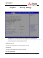
Security Settings
If the Administrator password is defined ONLY - this controls access to the BIOS setup ONLY.
If the User's password is defined ONLY - this password will need to be entered during each system startup
or boot, and will also have Administrator rights in the setup.
Passwords must be at least 3 and up to 20 characters long.
Administrator Password
Press Enter to create a new, or change an existing Administrator password.
User Password:
Press Enter to create a new, or change an existing User password.
Boot Sector Virus Protection
Copyright © 2012 American Megatrends Inc. ● Public Document (PUB)
Page 20 of 28
UEFI Development PC
Setup User Manual
When Enabled, the BIOS displays a warning when any program (or virus) issues a Disk Format command, or
attempts to write to the boot sector of the hard disk drive. The options are Enabled and Disabled.
Secure Boot Control
When Enabled, Secure boot is enabled from the UEFI firmware. Secure Boot is possible only if the system runs in
User Mode. (Refer Security Key Database Management Demo). Disabled to Turn off the UEFI Secure Boot
feature. OpROM from Off Board cards are note launch when Secure Boot is enabled.
Secure Boot Policy
The following options set the Image Execution Policy on Security Violation. Allows to decide the when secure
boot is enabled, which kind of Images executed/Denied
Internal FV
The option is Always Execute.
Option ROM
The options are Always Execute, Always Deny, Allow Execute, Defer Execute, Deny Execute, and Query User.
Removable Media
The options are Always Execute, Always Deny, Allow Execute, Defer Execute, Deny Execute, and Query User.
Fixed Media
The options are Always Execute, Always Deny, Allow Execute, Defer Execute, Deny Execute, and Query User.
**If additional information is needed regarding Security Settings, please contact AMI to acquire it under NonDisclosure Agreement (NDA)
Copyright © 2012 American Megatrends Inc. ● Public Document (PUB)
Page 21 of 28
UEFI Development PC
Setup User Manual
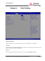
Chapter 4
Boot Settings
Setup Prompt Timeout
Number of seconds to wait for setup activation key. Enter 65535 (OXFFFF) to wait indefinitely.
Fast Boot
This feature allows booting with initialization with a minimal set of devices required to launch an active boot
option. The options are Disabled, and Enabled.
Skip VGA
This feature allows the BIOS to skip EFI VGA driver. The options are Disabled, and Enabled.
Copyright © 2012 American Megatrends Inc. ● Public Document (PUB)
Page 22 of 28
UEFI Development PC
Setup User Manual
Skip USB
If enabled USB devices will not be available until after OS Boot. Otherwise, USB devices will be available before
OS boot. The options are Disabled, and Enabled.
Skip PS2
This option allows PS2 devices to be skipped. The options are Disabled, and Enabled.
Boot Options Priority
This feature allows the user to specify which devices are boot devices and the order of priority from which the
systems boots from during startup.
Boot Option #1, Boot option #2, Boot Option #3, etc.
The settings are Built-in EFI Shell, [any detected boot device] and Disabled.
Network Devices
Boot Option #1, Boot option #2, Boot Option #3, etc.
Hard Disk Drives
Boot Option #1, Boot option #2, Boot Option #3, etc.
Delete Boot Option
This feature allows the removal of a boot device and the order of priority from which the systems boots from
during startup.
Copyright © 2012 American Megatrends Inc. ● Public Document (PUB)
Page 23 of 28
UEFI Development PC
Setup User Manual
Chapter 5
Exit Options
Select the Exit tab from the BIOS Setup Utility screen to enter the Exit BIOS Setup screen.
Save Changes and Exit
When you have completed the system configuration changes, select this option to leave the BIOS Setup Utility and
reboot the computer, so the new system configuration parameters can take effect. Select Save Changes and Exit
from the Exit menu and press <Enter>.
Discard Changes and Exit
Select this option to quit the BIOS Setup without making any permanent changes to the system configuration, and
reboot the computer. Select Discard Changes and Exit from the Exit menu and press <Enter>.
Discard Changes
Select this option and press <Enter> to discard all the changes and return to the AMI BIOS Utility Program.
Copyright © 2012 American Megatrends Inc. ● Public Document (PUB)
Page 24 of 28
UEFI Development PC
Setup User Manual
Restore Defaults
To set this feature, select Restore Defaults from the Exit menu and press <Enter>. These are factory settings
designed for maximum system stability, but not for maximum performance.
Save As User Defaults
To set this feature, select Save as User Defaults from the Exit menu and press <Enter>. This enables the user to
save any changes to the BIOS setup for future use.
Restore User Defaults
To set this feature, select Restore User Defaults from the Exit menu and press <Enter>. Use this feature to retrieve
user-defined settings that were saved previously.
Boot Override
Set this feature to override a previously defined boot device. The available Boot Options will be listed below.
Launch EFI Shell from filesystem device
This feature when initiated, will attempt to launch an EFI shell application (shellx64.efi) from one of the available
file system devices. Press <Enter> to activate.
Copyright © 2012 American Megatrends Inc. ● Public Document (PUB)
Page 25 of 28
UEFI Development PC
Setup User Manual
Appendix
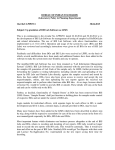
BIOS Flash Instructions
In order to flash the BIOS on the platform, you will download an updated BIOS .ROM image for your platform
from AMI’s support website or receive the image from AMI support.
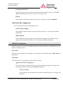
Before flashing a new image onto the system, it is recommended that the current BIOS image be backed up to a
file. Double-click on the AFUWINx64 or any other version of the AFU application:
Issue the command AFUWINx64.EXE <ROM_File_Name> /O where ROM_File_Name can be any .ROM file
like old.rom to backup the existing image on the system.
Now, flash the new BIOS image to the system:
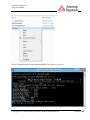
Select the Setup batch file to begin the BIOS update
Right click on the Setup batch file and select Run as administrator from the drop down menu
Copyright © 2012 American Megatrends Inc. ● Public Document (PUB)
Page 26 of 28
UEFI Development PC
Setup User Manual
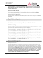
This will launch the batch file and update the BIOS on the system as seen below:
Copyright © 2012 American Megatrends Inc. ● Public Document (PUB)
Page 27 of 28
UEFI Development PC
Setup User Manual
Once the batch file has executed, restart the system for the BIOS update changes to take effect.
Copyright © 2012 American Megatrends Inc. ● Public Document (PUB)
Page 28 of 28