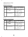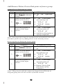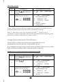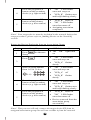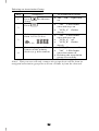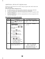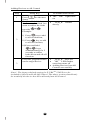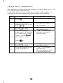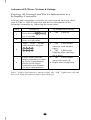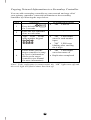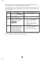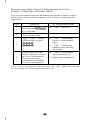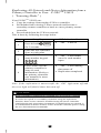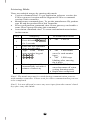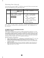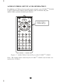
1
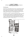
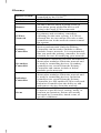
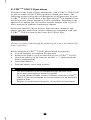
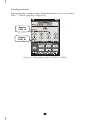
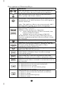
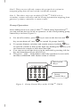
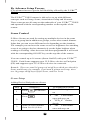
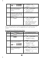
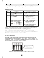
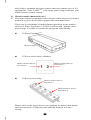
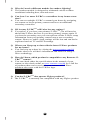
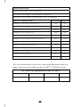
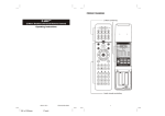
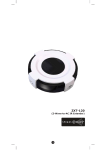
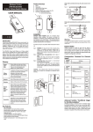
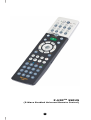
Z-URCTM 550US
(Z-Wave Enabled Universal Remote Control)
1
Table of Contents
Introduction .................................................... 4
Glossary .......................................................... 5
Z-URCTM 550US Operations ............................. 6
Configurations ................................................. 7
Description of Setup Keys.................................. 8
Group Control .................................................. 9
XpressZetupTM (Group Setup) ........................... 9
Group Operation .............................................. 11
Scene Control .................................................. 12
Scene Setup .................................................... 12
Scene Operation............................................... 14
Additional Device Setups ................................. 15
Add/Delete Devices .......................................... 15
Add/Remove/Delete Device/EP to/from a group ... 16
Assign Association for Two Devices .................... 17
Add/Delete All-On/All-Off functions .................... 20
Change Device Configuration ............................ 22
Advanced Z-Wave Network Setups .................. 23
Copying All Network and Device Information to a
Secondary Controller ........................................ 23
Copying Network Information to a Secondary
Controller ........................................................ 24
Transferring All Network and Device Information
to a New Primary Controller (Primary shift) ......... 25
Transferring Only Network Information to a New
Primary Controller (Primary shift) ....................... 26
Replicating All Network and Device Information
from a Primary Controller to your Z-URCTM 550US
(Learning Mode)............................................... 27
Listening Mode................................................. 28
Resetting Your Network..................................... 29
WIRELESS INFORMATION ............................... 29
AUDIO/VIDEO SETUP AND OPERATION........... 30
Description of Audio/Video Control Keys .............. 31
AV Equipment Selection by Entering Device Code . 33
AV Equipment Selection by Searching through
the Library ...................................................... 34
2
Learning IR Commands ..................................... 35
Operating the Z-URCTM 550US for AV Equipment .. 36
ADVANCED OPERATION FOR AV EQUIPMENT .. 38
Secondary Function .......................................... 38
IR Boost Mode ................................................. 38
Restore Factory Settings ................................... 39
MAINTENANCE................................................. 39
FREQUENTLY ASKED QUESTIONS .................... 39
Z-Wave Frequently Asked Questions ................... 39
AV Control Frequently Asked Questions ............... 42
TECHNICAL SPECIFICATIONS .......................... 42
CHECKING THE ACCESSORIES ......................... 44
FCC NOTICE .................................................... 44
WARNINGS ...................................................... 44
3
Z-URCTM 550US
(Z-Wave Enabled Universal Remote Control)
Operating Instructions
Introduction
The Z-URCTM 550US Z-Wave AV Controller is a universal AV remote
and also a Z-Wave controller (Figure 1). As a universal remote, the ZURCTM 550US replaces all your AV remotes through its built-in IR
code database or IR code learning. As a Z-Wave controller, the ZURCTM 550US works with Z-Wave enabled devices, support multichannel command class devices and controls their on/off or up/down
individually, as a Group, or via a pre-configured Scene.
A perfect kit of Z-URCTM 550US and ZXT-300US (Z-Wave-to-AV IR
Extender). It works with any Z-Wave compliant controller or gateway
by translating Z-Wave Simple AV command to IR control code.
User can set the IR code from the built-in code library of ZXT-300US,
or use the learning function of ZXT-300US through the simple UI of
Z-URCTM 550US. User can also download the preset code or learnt
command from Z-URCTM 550US to ZXT-300US. User can enjoy the
fully wireless control in anywhere at home.
Z-Wave control key (can be Group On/Off or Scene On/Off)
Audio visual control key
Figure 1 Z-URCTM 550US
4
Glossary
Device or Node
Inclusion
Exclusion
Remove
Z-Wave
Network
Primary
Controller
Secondary
Controller
Inclusion
Controller
Scene
Z-Wave enabled device that can be
controlled by the Z-URCTM.
Add a Z-Wave device to the network.
Delete a Z-Wave device from the network.
To take a device out of a group, scene or
association group while that device still
exists in the same Z-Wave network.
A collection of Z-Wave devices controlled
by primary and secondary controllers
operating on the same system. A Z-Wave
network has its own unique ID code so that
controllers not in the network cannot control
the system.
The first controller used to set up your
devices and network. Only the Primary
Controller can be used to include or delete
modules from a network. It is recommended
that you mark the primary controller for each
network for ease in modifying your network.
A controller containing network information
about other modules within the network and
is used for controlling devices. Secondary
controllers are created from the Primary
Controller and cannot include or delete
modules to the network.
A controller containing network information
about other modules within the network and
is used for controlling devices. Inclusion
controllers are created from the Primary
Controller in a SIS enabled Z-Wave network.
Inclusion Controller has the ability to add
and remove devices from the network.
A collection of Z-Wave devices configured
to turn to a specific level, setting, mode, or
perform an operation. Scenes are usually
activated by a controller, timed event, or
specific conditions.
5
Z-URCTM 550US Operations
Welcome to the world of home automation, your Z-URCTM 550US will
be able to control all the Z-Wave products around your house. The
following section will guide you through the set up processes for your
Z-URCTM 550US. Firstly there is the XpressZetupTM for beginner users
that do not have a large amount of Z-Wave products. Following is the
advanced set up that you will need to become familiar with as your ZWave network of products continues to expand.
Please note that all Z-Wave devices, light switches, dimmers, and
shutter switches made from various vendors are compatible with your
Z-URCTM 550US as long as they carry the Z-Wave logo:
(Please carefully read through the following then store the manual for
future reference.)
Before using the Z-URCTM 550US, please install the batteries:
• 3xAAA batteries are required for operation.
• Remove the battery cover on the back of your Z-URCTM 550US.
• Check the polarity of the batteries and the "+/-" marks inside the
battery compartment.
• Insert the batteries.
• Push the battery cover back in place.
L CAUTION (battery safety)
−
−
−
−
Use new batteries of the recommended type and size only.
Never mix used and new batteries together.
To avoid chemical leaks, remove batteries from the Z-URCTM
550US if you do not intend to use the remote for an extended
period of time.
Dispose of used batteries properly; do not burn or bury them.
6
Configurations
Please open the configuration compartment then you can see the ZURCTM 550US setup keys (Figure 2).
Status
LED_A
Status
LED_B
Figure 2 Setup Keys of the Z-URCTM 550US
7
Description of Function Keys
Keys
Functions
The All-On and All-Off keys are used for turns on
or off all Z-Wave devices in the device database.
The On and Off keys are used for the different ZWave groups and scenes control.
Press once to access secondary functions for the
next button. Press and hold to activate shift lock for
permanent use of shift functions. Press shift again to
release shift lock.
Note: The shift key allows you access group's shift 1
through shift 8 giving you a total of 16 groups.
The ADD and REMOVE keys are used during
XpressZetupTM process.
ADD key will perform two functions:
• Add a target device to Z-Wave network, also
known as INCLUSION;
• Add the device to the assigned GROUP.
REMOVE key will only remove the target device
from its assigned group but will not exclude it from
the network.
This SHIFT key is used for accessing group
numbers 9 to 16 while programming your devices.
These are your group numbers 1 through 8 and also
become group numbers 9 through 16 when
combined with the SHIFT key.
This Configuration key is used during the
ADVANCED SETUP process.
This Association key is used in conjunction with
Add, Delete or Remove keys in order to assign
association groups.
This Scene key is used in conjunction with Add,
Delete or Remove keys in order to program scenes.
This Device key is used in conjunction with Add,
Delete keys in order to include or exclude devices to
the network.
This Add key is used in the Advance Setup to:
• Add a device to the network (inclusion);
• Add a device to a group;
• Add a device to an association group;
• Add a device to a scene.
This Delete key is used in the Advance Setup to:
• Delete a device from the network (exclusion);
• Delete a group;
• Delete an association group;
• Delete a scene.
8
This Remove key is used in the Advance Setup to:
• Remove a device from a group;
• Remove a device from an association group;
• Remove a device from a scene.
Group Control
The Z-URCTM 550US enables you to control single or multiple ZWave devices with the press of a button. For example, you can group
all your bedroom lights together so that all of them will turn on with
the press of a button.
You can control up to 16 groups (Group On/Off) with your Z-URCTM
550US. Each Group supports up to 32 Z-Wave devices or End-point
(EP) and supports up to 232 Z-Wave devices in a network.
Remark: There are total 16 groups of on/off keys which are shared by
Scene and Group, for example, if you used 6 groups as Group, there
are 10 groups on/off keys left for Scene, and vise versa.
XpressZetupTM (Group Setup)
Including Device to a Group
Step
1
Setup Key
LED Indication Status
• “OK" LED on
Press
in
XpressZetupTM area
• “LED_A" flashes
rapidly
• “LED_A" off
Select a group number
from 1 to 16 (1-8 or
2
• “LED_B" flashes
rapidly
1-8)
Press the program button
on the target device
3
• “OK" LED flashes
once then turns off
• “LED_B" off
• Group setup completed
Note1: If you cannot add your Z-Wave device, this device might have
been included in another Z-Wave network. In this case, please delete
this device following the steps in the [Deleting Device from the
Network] section then add this device again.
9
Note2: XpressZetupTM cannot support “Multi-Channel Device”, please
refer to [Adding Device to the Network] and [Adding Device/End-point
to a group] for normal setup procedure.
Removing Device from a Group
Step
1
2
Setup Key
LED Indication Status
• “OK" LED on
Press
in
XpressZetupTM area
• “LED_A" flashes
rapidly
• “LED_A" off
Select a group number
from 1 to 16 (1-8 or
• “LED_B" flashes
rapidly
1-8)
3
Press the program button
on the target device
• “OK" LED flashes once
then turns off
• Device been removed from
the Group successfully
Note1: If the ERROR LED turns on or flashes, meaning the setup
process is failed. Please redo the process.
Note2: XpressZetupTM cannot support “Multi-Channel Device”, please
refer to [Removing Device/End-point from a group] for normal setup
procedure.
Note3: This process will only remove the target device from its
assigned group but will not exclude it from the network.
Removing all Devices from a Group
Step
1
Setup Key
LED Indication Status
• “OK" LED on
Press and hold
in XpressZetupTM area
• “LED_A" flashes
rapidly
• “LED_A" off
Select a group number
from 1 to 16 (1-8 or
2
• “LED_B" flashes
rapidly
1-8)
• “OK" LED flashes once
then turns off
• Device been deleted from
the Group successfully
Note1: If the ERROR LED turns on or flashes, meaning the setup
process is failed. Please redo the process.
10
Note2: This process will only remove the group devices from its
assigned group but will not exclude it from the network.
Note 3: The above steps are needed if Z-URCTM 550US to be a
secondary remote controller and the Group information mapping from
gateway / primary controller is unsuccessful.
Group Operation
After adding devices to your Z-URCTM 550US using XpressZetupTM,
you can turn the device on/off or up/down via the corresponding group
control keys in front (Figure 3).
•
For on/off switches, press
key to turn on the devices and
key to turn them off. (use
to extend 16 groups On/Off)
•
To operate dimmer switches and curtain motors, hold the
•
•
key
to open the curtain or dim up the light. By holding the
key you
can retract the curtain or dim down the light.
You can turn on all the devices in the network by pressing All-On
key and turn them off via All-Off key.
The green “OK" LED flashes when the operation is successful,
and the red ERROR LED flashes when it’s failed.
All On/Off
Keys
Group
Control Keys
Figure 3 Group Control Keys of the Z-URCTM 550US
11
By Advance Setup Process
(For advanced users to get the full flexibility offered by the Z-URCTM
550US)
The Z-URCTM 550US remote is able to be set up with different
concepts such as Group, Scene, Association Group and Network.
These concepts are all setup on the underside of your Z-URCTM 550US
and operated with the corresponding number on the topside of the
remote.
Scene Control
Z-Wave Scenes are used for setting up multiple devices in the same
way as a group but in addition to groups, scenes also control dimmer
lights that you can set to different levels depending on the situation.
For example you can have the scene set to low brightness for watching
a movie or going to bed or alternatively set the lights brighter when
reading or working. After the scene has been programmed it will work
with the corresponding ON OFF key on the top side of the remote.
You can control up to 16 scenes (Scene On/Off) with your Z-URCTM
550US. Each Scene supports up to 32 Z-Wave devices or End-point
(EP) and supports up to 232 Z-Wave devices in a network.
Remark: There are total 16 groups of on/off keys which are shared by
Scene and Group, for example, if you used 6 groups as Group, there
are 10 groups on/off keys left for Scene, and vise versa.
Scene Setup
Adding Device/End-point to a Scene
Step
1
Setup Key
Press
Setup
LED Indication Status
in Advance
• “OK" LED flashes
once and stays on
Press
2
3
• The “OK" light turns
on
• “LED_A" flashes
slowly
Select a scene number
from 1 to 16 (1-8 or
12
• “OK" LED flashes
once and stays on
• “LED_A" off
• “LED_B" flashes
slowly
1-8)
4
5
• “OK" LED flashes
once and stays on
Press the program/EP
button on the target
device
• “LED_B" keep
blinking slowly
Adjust the target device
on/off or dim level with
its program button, to the
desired status
-
• “OK" LED flashes
once then turns off
Press
• “LED_B" off
6
• The current status of the
device will be learned
and saved to a scene
successfully
Note1: Your target device must be included in the network before this
setup procedure, please refer to [Adding Device to the Network]
section.
Removing Device/End-point from a Scene
Step
1
Setup Key
Press
Setup
LED Indication Status
in Advance
• “OK" LED flashes
once and stays on
Press
2
• “LED_A" flashes
slowly
Select a scene number
from 1 to 16 (1-8 or
• “OK" LED flashes
once and stays on
• “LED_A" off
3
1-8)
4
• The “OK" light turns
on
• “LED_B" flashes
slowly
• the “OK" light stays
on then flashes once and
turns off
Press the program/EP
button on the target
device
• “LED_B" off
• Device removed from the
13
scene successfully
Note1: This process will only remove the target device/EP from its
assigned scene but will not exclude it from the network.
Deleting a Scene
Step
1
Setup Key
Press
Setup
LED Indication Status
in Advance
• The “OK" light turns
on
• “OK" LED flashes
once and stays on
Press
2
• “LED_A" flashes
slowly
Select a scene number
from 1 to 16 (1-8 or
• “OK" LED flashes
once then turns off
• “LED_A" off
3
1-8)
• Scene deleted from the
scene successfully
Note1: This process will only remove the scene devices/EPs from its
assigned scene but will not exclude it from the network.
Note 2: The above steps are needed if Z-URCTM 550US to be a
secondary remote controller and the Scene information mapping from
gateway / primary controller is unsuccessful.
Scene Operation
After the scene setup is done, you can trigger the desired scene via
scene control keys in front panel of the Z-URCTM 550US. (Figure 4)
The green “OK" LED flashes when the operation is successful, and
the red ERROR LED flashes when it’s failed.
Scene
Control Keys
Figure 4 Scene Control Keys of the Z-URCTM 550US
14
Additional Device Setups
Add/Delete Devices
Adding Device to the Network
Step
1
Setup Key
Press
Setup
LED Indication Status
in Advance
• The “OK" light turns
on
• “OK" LED flashes
once and stays on
Press
2
• “LED_B" flashes
slowly
Press the program button
on the target device
• “OK" LED flashes
once then turns off
• “LED_B" off
3
• Device inclusion
completed
Note1: This step can be skipped if the device is already included in the
network.
Deleting Device from the Network
Step
1
Setup Key
Press
Setup
LED Indication Status
in Advance
• The “OK" light turns
on
• “OK" LED flashes
once and stays on
Press
2
• “LED_B" flashes
slowly
Press the program button
on the target device
• “OK" LED flashes
once then turns off
• “LED_B" off
3
• Device exclusion
completed
15
Add/Remove/Delete Device/End-point to/from a group
Adding Device/End-point to a group
Step
1
Setup Key
Press
Setup
LED Indication Status
in Advance
Select a group number
from 1 to 16 (1-8 or
• “OK" LED flashes
once and stays on
• “LED_A" off
2
1-8)
3
• The “OK" light turns
on
• “LED_B" flashes
slowly
• “OK" LED flashes
once then turns off
Press the program/EP
button on the target
device
• “LED_B" off
• Add Device/End-point to
a group completed
Note1: Your target device must be included in the network before this setup
procedure, please refer to [Adding Device to the Network] section.
Removing Device/End-point from a group
Step
1
Setup Key
Press
Setup
LED Indication Status
in Advance
Select a group number
from 1 to 16 (1-8 or
• The “OK" light turns
on
• “OK" LED flashes
once and stays on
• “LED_A" off
2
1-8)
• “LED_B" flashes
slowly
• “OK" LED flashes
once then turns off
Press the program/EP
button on the target
device
• “LED_B" off
3
• Remove Device/Endpoint from a group
completed
Note1: This process will only remove the target device/EP from its
assigned group but will not exclude it from the network.
16
Deleting a group
Step
1
Setup Key
Press
Setup
LED Indication Status
in Advance
Select a group number
from 1 to 16 (1-8 or
• The “OK" light turns
on
• “OK" LED flashes
once and stays on
• “LED_A" off
2
1-8)
• “LED_B" flashes
slowly
• Delete a group
completed
Note1: This process will only remove the group devices/EPs from its
assigned group but will not exclude it from the network.
Note 2: The above steps are needed if Z-URCTM 550US to be a
secondary remote controller and the Group information mapping from
gateway / primary controller is unsuccessful.
Assign Association for Two Devices
The Z-URCTM 550US can be used to assign one device to
automatically interact directly with another device.
For example you can assign a door sensor (primary node) to turn on the
light switch (secondary node) when the door is opened.
Adding Device/End-point to an Association Group
Step
1
Setup Key
Press
Setup
LED Indication Status
in Advance
• The “OK" light turns
on
• “OK" LED flashes
once and stays on
Press
2
• “LED_A" flashes
slowly
Select a group number
from 1 to 16 (1-8 or
• “OK" LED flashes
once and stays on
• “LED_A" off
3
1-8)
• “LED_B" flashes
slowly
17
4
5
Press the program/EP
button on the secondary
device (e.g. light switch)
Press the program/EP
button on the primary
device (e.g. door sensor)
• “OK" LED flashes
once and stays on
• “LED_B" flashes once
and keep blinking slowly
• “LED_B" turns off
• “OK" LED flashes
once then turns off
• Assigning association
completed
Note1: Your target device must be included in the network before this
setup procedure, please refer to [Adding Device to the Network]
section.
Removing Device/End-point from an Association Group
Step
1
Setup Key
Press
Setup
LED Indication Status
in Advance
• “OK" LED flashes
once and stays on
Press
2
• “LED_A" flashes
slowly
Select a group number
from 1 to 16 (1-8 or
• “OK" LED flashes
once and stays on
• “LED_A" off
3
1-8)
4
• The “OK" light turns
on
• “LED_B" flashes
slowly
Press the program/EP
button on the secondary
device (e.g. light switch)
Press the program/EP
button on the primary
device (e.g. door sensor)
5
• “OK" LED flashes
once and stays on
• “LED_B" flashes once
and keep blinking slowly
• “LED_B" turns off
• “OK" LED flashes
once then turns off
• Device removed from the
association group
successfully
Note1: This process will only remove the target device/EP from its
assigned association group but will not exclude it from the network.
18
Deleting an Association Group
Step
1
Setup Key
Press
Setup
LED Indication Status
in Advance
• “OK" LED flashes
once and stays on
Press
2
• “LED_A" flashes
slowly
Select a group number
from 1 to 16 (1-8 or
3
1-8)
4
• The “OK" light turns
on
Press the program/EP
button on the primary
device (e.g. door sensor)
• “OK" LED flashes
once and stays on
• “LED_A" off
• “LED_B" flashes
slowly
• “LED_B" turns off
• “OK" LED flashes
once then turns off
• Deleting the association
group successfully
Note1: This process will only remove the group devices/EPs from its
assigned association group but will not exclude it from the network.
19
Add/Delete All-On/All- Off functions
If desired, specific devices can be setup to ignore the All-On and AllOff commands.
The four possible responses are:
• It will respond to All-On and the All-Off commands (default).
• It will not respond to All-On and All-Off commands.
• It will respond to the All-Off command but will not respond to the
All-On command.
• It will respond to the All-On command but will not respond to the
All-Off command
Deleting Devices from All Control
Step
1
Setup Key
Press
Setup
LED Indication Status
in Advance
Press and hold the key
for 2 seconds which you
want to delete from the
• The “OK" light turns
on
• “LED_B" flashes
slowly
front top side
Example:
i) Press
key to
delete from all-on
function,
2
ii) Press
key to
delete from all-off
function,
iii) Press and hold
keys
simultaneously for 2
seconds to delete
from both all-on and
all-off function.
Press the program button
on the target device
3
20
• “LED_B"turns off
• “OK" LED flashes
once then turns off
• Delete Device from All
Control successfully
Adding Devices to All Control
Step
1
Setup Key
Press
Setup
LED Indication Status
in Advance
Press and hold the key
for 2 seconds which you
want to add to the front
• The “OK" light turns
on
• “LED_B" flashes
slowly
top side
Example:
i) Press
key to add
to all-on function,
2
ii) Press
key to add
to all-off function,
iii) Press and hold
keys
simultaneously for 2
seconds to add to
both all-on and all-off
function.
Press the program button
on the target device
3
• “LED_B"turns off
• “OK" LED flashes
once then turns off
• Adding Device from All
Control successfully
Note1: The factory default setting for Z-URCTM 550US is to be
included in All-On and All-Off control. The above section should only
be needed if the device has been deleted from All Control.
21
Change Device Configuration
This function is used to modify the parameter of the Z-Wave device via
the configuration command class.
Look up the Parameter No. and Parameter Value of the target device
from the device user manual before you start the below process.
Step
Setup Key
LED Indication Status
• “OK" LED stays on
1
Press
2
Enter the Parameter
number from 0 to 255 in
front
3
Press
4
Enter the Parameter
value from -2147483648
to +2147483648 (32bits
value) in front
(For negative value,
5
6
in front
press
)
Press
in front
Press the program button
on the target device
22
• “OK" LED flashes
once and stays on for
each key press
• “OK" LED stays on
then flashes once
• “OK" LED flashes
once and stays on for
each key press
• “OK" LED stays on
then flashes once
• “OK" LED flashes
and turns off
• The configuration value
is saved to the device
Advanced Z-Wave Network Setups
Copying All Network and Device Information to a
Secondary Controller
You can add a secondary controller to your network and copy all of
your Z-URCTM 550US’s network and device information to the
secondary controller by following the steps below.
Step
Setup Key
LED Indication Status
• “OK" LED on
1
Press & hold
for 3 seconds
2
Place the two controller
close to each other
Type “8541" on the
setup number keypad
3
4
• “OK" LED flashes
once for each number
input
• “OK" LED keeps
blinking after entering
the 4-digit
Please make sure the
target controller is setup
to receive information.
(Refer to the target
controller user manual
for more information)
• “OK" LED flashes
once then turns off
• Replication completed
Note1: If this replication is unsuccessful, the “OK” light turns off and
the error light will flash 6 times then turn off.
23
Copying Network Information to a Secondary Controller
You can add a secondary controller to your network and copy all of
your primary controller’s network information to the secondary
controller by following the steps below.
Step
Setup Key
LED Indication Status
• “OK" LED on
1
Press & hold
for 3 seconds
2
Place the two controller
close to each other
Type “8542" on the
setup number keypad
3
4
• “OK" LED flashes
once for each number
input
• “OK" LED keeps
blinking after entering
the 4-digit
Please make sure the
target controller is setup
to receive information.
(Refer to the target
controller user manual
for more information)
• “OK" LED flashes
once then turns off
• Replication completed
Note1: If the replication is unsuccessful, the “OK” light turns off and
the error light will flash 6 times then turn off.
24
Transferring All Network and Device Information to a
New Primary Controller (Primary Shift)
You can transfer all of your controller information to another remote so
that it will become the new primary remote. This is done by following
the steps below.
Step
Setup Key
LED Indication Status
• “OK" LED on
1
Press & hold
for 3 seconds
2
Place the two controller
close to each other
Type “8361" on the
setup number keypad
3
4
• “OK" LED flashes
once for each number
input
• “OK" LED keeps
blinking after entering
the 4-digit
Please make sure the
target controller is setup
to receive information.
(Refer to the target
controller user manual
for more information)
• “OK" LED flashes
once then turns off
• Replication completed
Note1: If this replication is unsuccessful, the “OK” light turns off and
the error light will flash 6 times then turn off.
25
Transferring Only Network Information to a New
Primary Controller (Primary Shift)
You can just transfer network information to another remote so that it
will become the new primary remote. This is done by following the
steps below.
Step
Setup Key
LED Indication Status
• “OK" LED on
1
Press & hold
for 3 seconds
2
Place the two controller
close to each other
Type “8362" on the
setup number keypad
3
4
• “OK" LED flashes
once for each number
input
• “OK" LED keeps
blinking after entering
the 4-digit
Please make sure the
target controller is setup
to receive information.
(Refer to the target
controller user manual
for more information)
• “OK" LED flashes
once then turns off
• Replication completed
Note1: If this replication is unsuccessful, the “OK” light turns off and
the error light will flash 6 times then turn off.
26
Replicating All Network and Device Information from a
Primary Controller to Your Z-URCTM 550US
(“Learning Mode")
Your Z-URCTM 550US can:
• Copy the settings from another Z-Wave controller
• Be included into existing Z-Wave network and become a
secondary remote controller or back to a new primary remote
controller
• Be excluded from the Z-Wave network
This is done by following the steps below.
Step
Setup Key
LED Indication Status
• “OK" LED on
1
Press & hold
for 3 seconds
2
Place the two controller
close to each other
3
4
Type “8363" on the
setup number keypad
• “OK" LED flashes
once for each number
input
Please make sure the
primary controller is
setup to send
information. (Refer to
the primary controller
user manual for more
information)
• “OK" LED blinking
then turns off
• Replication completed
Note: If the replication is unsuccessful, the “OK” light turns off and
the error light will flash 6 times then turn off.
L CAUTION
Scene Controller Configuration Command and Association Command
If scenes are copied to a secondary controller using the replication
function, those scenes cannot be modified using the Scene Controller
Configuration and Association Commands. If modifications are desired, it
is recommended to delete all these scenes from the controller prior to using
the two aforementioned commands.
27
Listening Mode
There are multiple usages by entering this mode:
• Version command class: To get application software version, the
Z-Wave protocol version and the supported Z-Wave command
version of this controller.
• Manufacturer command class: To get the manufacture ID, product
type ID and the product ID of this controller.
• Scene configuration command class: Home gateway can bundle a
scene ID to a group ID using this command.
• Association command class: To create and maintain associations
in this remote.
Step
Setup Key
LED Indication Status
• “OK" LED on
1
Press & hold
for 3 seconds
2
Place the two controller
close to each other
Type “8364" on the
setup number keypad
3
4
• “OK" LED flashes
once for each number
input
• “OK" LED keeps
blinking after entering
the 4-digit
Listening mode will
automatically exit after 1
minute of inactivity
• “OK" LED flashes
once then turns off when
exiting listening mode
• Replication completed
Note1: The mode must not be exited during communication process
with another controller. Please wait for entire communication process
to be completed.
Note2: It is not allowed to enter any user input from the remote's hard
key after entry this Mode.
28
Resetting Your Network
You can reset your Z-URCTM 550US to clear all Z-Wave network and
device information by the following steps:
Step
1
Setup Key
LED Indication Status
• “OK" LED on
Press & hold
for 3 seconds
Type “8761" on the
setup number keypad
• “OK" LED flashes
once for each number
input
• “OK" LED on after
entering the 4-digit
2
• “OK" LED blinking
then turns off
• Reset completed
Note: After reset the remote, each device should individually perform in
the section on “Delete device from the network” and “Add device to
the network”.
WIRELESS INFORMATION
Wireless range:
This device has an open air line of sight transmission distance of 100
feet which complies with the Z-Wave standards. Performance can vary
depending on the amount of objects in between Z-Wave devices such
as walls and furniture. Every Z-Wave device set up in your house will
act as a signal repeater allowing devices to talk to each other and find
alternate routes in the case of a reception dead spot.
Radio frequency limitations:
1. Each wall or object (i.e.: refrigerator, bookshelf, large TV, etc) can
reduce the maximum range of 65 feet by up to 25 to 30%.
2. Plasterboard and wooden walls block less of the radio signal then
concrete, brick or tile walls which will have more of an effect on
signal strength.
3. Wall mounted Z-Wave devices will also suffer a loss of range as
they are housed in metal junction boxes which could reduce the
range by up to 25 to 30%.
29
AUDIO/VIDEO SETUP AND OPERATION
In addition to Z-Wave device and scene control, your Z-URCTM 550US
is also a universal remote which enables you to control all your
audio/video systems around your house.
Audio/Video
Control Keys
Figure 5 Audio/Video Control Keys of the Z-URCTM 550US
Note: The audio/video control of the Z-URCTM 550US can be done via
infrared or Z-Wave.
30
Description of Audio/Video Control Keys
The Z-URCTM 550US operates up to 8 AV equipments which are
accessed by using the SHIFT key and TV or DVD and so on.
Note: The SHIFT key is used when operating both the AV and Z-Wave
equipments
Press once to access secondary function
for the next button. Press and hold to
activate shift lock for permanent use of
secondary functions. Press shift again to
release shift lock
Selects TV mode
Selects satellite, cable receiver or similar
devices such as DVB-T, IPTV, etc
On/off key for selected AV equipment
Selects DVD player or other optical disc
players such as Blue Ray, PVR, or CD
player
Selects Auxiliary mode normally assigned
to audio equipment
Scrolls through AV modes while in TV
mode; also my DVR when in shift mode
Selects guide while in SAT/CBL mode;
also on demand when in shift mode
Changes volume level of the device; also
in shift mode changes the day when
operating your SAT/CBL device
Changes the channels when in TV, DVR,
or SAT/CBL mode; also in shift mode
changes the page number while operating
your SAT/CBL device
Mute the audio
Return to the previous channel
4-way directional pad for navigating onscreen menu and “OK” button for
selecting menu options
31
Menu, also List when in shift mode
Exit, also Live for SAT/CBL mode when in
shift mode
Previous track
Next track
Stop
Record
Rewind
Play
Pause
Fast forward
Numeric number 1; also in shift mode can
be either triangle/A or yellow button for TV
or SAT/CBL menus
Numeric number 2; also in shift mode can
be either square/B or blue button for TV or
SAT/CBL menus
Numeric number 3; also in shift mode can
be either circle/C or red button for TV or
SAT/CBL menus
Info while in SAT/CBL or TV mode; also in
shift mode will be diamond/D or green
button for TV or SAT/CBL menus
Numeric numbers 4,5,6,7,8,9,0
Closed caption for teletext; also Active
when in shift mode
Aspect ratio control
32
Activates picture in picture mode
Dash for HDTV
Enter
AV Equipment Selection by Entering Device Code
You may setup the Z-URCTM 550US by following the code entering
instructions:
1. Referring to the DEVICE CODE LIST, look up the 4-digit Device
Code which corresponds to the brand of your A/V equipment. If
there is more than one Device Code listed under your brand, start
from the first code.
2. Press the desired Device Mode Key (e.g. TV).
3. Press and hold "CH +" and "VOL -" on the Z-URCTM 550US
simultaneously for 3 seconds until the green indicator lights up.
4. Use the number keys "0" - "9" to enter your 4-digit Device Code.
The indicator flashes twice then goes out.
Turn on your device (e.g. TV), then try the function keys on the ZURCTM 550US. If your device (e.g. TV) responds to your activated
function correctly, you have entered the right Device Code. Otherwise,
repeat the above steps with the next available Device Codes until your
device (e.g. TV) responds to your activated function, and most keys
work correctly.
• Simply repeat the above procedures to enter the Device Codes for
your SAT/CBL, DVD or AUX. (Remember to press the correct
Device Mode Key in step 2 above)
Note: If the red indicator flashes 6 times in step 4, a wrong Device
Code has been entered. You are required to repeat step 2 to 4 again.
Suggestions:
• If you cannot find a correct Device Code for your equipment, refer
to AV Equipment Selection by Searching through the Library.
• For future reference you are recommended to take note of your
Devices codes in the space provided in the manual after setting up
the Z-URCTM 550US correctly.
33
AV Equipment Selection by Searching through the
Library
If you cannot identify a correct Device Code for your equipment from
the Device Code list, you may search for the code in the library:
1. Turn on your device manually (e.g. TV).
2. Press a desired Device Mode Key (e.g. TV).
3. Press and hold "CH +" and "VOL -" on the Z-URCTM 550US
simultaneously for 3 seconds until the indicator lights up.
4. Enter a corresponding Magic Search Code from the following
table. The green indicator flashes twice then goes out.
Device to be searched from
code library
TV
VCR/DVR/LASER DISC
SAT
CABLE / DVR+CABLE
COMBOS
DVD/DVD-R/RW/DVR+DVD
COMBOS
AUDIO
CD
HOME AUTOMATION
Magic Search
Code
0001
0002
0003
0004
0005
0006
0007
0008
(e.g. press "TV" device mode key, then press "CH +" and "VOL -", and
enter TV Magic Search Code 0001.)
5.
6.
7.
Press the same desired device mode key again as in step 2 above.
(e.g. TV)
Press and hold "CH +" & "VOL -" simultaneously for 3 seconds
until the green indicator lights up, and your Z-URCTM 550US is
ready to start searching.
Aim the Z-URCTM 550US at your device (e.g. TV), press the
key slowly and repeatedly until the device has been turned
off. Once your device has been turned off, immediately press
Device Mode Key (e.g. TV) to lock in code and the indicator
should go out.
*
Simply repeat the above setup procedures to search for the Device
Code for SAT/CBL, DVD or AUX. (Remember to press the
correct Device Mode Key and correct Magic Search Code in step
2-5 above)
34
L IMPORTANT
− If the power on/off function of your device is not infra-red
controlled, you need to follow steps 2 to 6 above and start
searching.
−
Press
and another function key alternately until your
device responds to the expected function, then press the same
Device Mode Key (e.g. TV) to lock in the code.
e.g.
−
Press
&
alternately, or ;
Press
&
alternately.
Notes:
−
TV, SAT/CBL, DVD, and other device codes can be searched
for and locked into any device modes. Simply press the
corresponding device mode key in step 2 & 5 and enter an
appropriate Magic Search Code for your DVD and other
devices.
−
Each time you press the
, the Z-URCTM 550US will skip
to the next code and send out a POWER signal trying to turn off
your device.
−
If you fail to stop pressing
when your device has been
turned off, turn your device on again immediately. Before the
green indicator goes out, press "Mute” on the Z-URCTM 550US
to skip backward. Repeat step 7 above and lock in the code.
If the red indicator flashes six times after your pressing of
−
key, you are already at the last code of the library.
Press "CH +" and "VOL -" to resume the Z-URCTM 550US and
repeat the above procedures carefully to search again.
Learning IR Commands
Your Z-URCTM 550US is equipped with learning capability. This
allows you to "teach" your Z-URCTM 550US certain functions from
your original equipment remote. Please follow the steps below.
1 Press the desired device mode key (e.g. TV).
2 Press and hold "CH+" and "VOL-" on the Z-URCTM 550US
simultaneously for 3 seconds until the green indicator lights up.
3 Enter the learning code "0", "0", "0", "0". The green indicator light
will flash once then stay lit. The Z-URCTM 550US is now ready to
learn.
4 Place the Z-URCTM 550US and your device remote on a flat
surface, aimed at each other 1-3 inches apart.
35
5
6
7
8
Press a desired key once and release on the Z-URCTM 550US
which you want to learn the command. The green indicator will
flash once then stay lit.
Press and keep holding the key on your original equipment remote
which you want to learn for a few seconds.
When the green indicator light flashes twice and stays lit
continuously, the command has been learned successfully and you
can release the key on your original equipment remote. If the red
indicator light flashes six times, it shows an error in the learning
process. Adjust the position of both remotes and repeat from step 5
again.
Repeat from step 5 to learn other key functions, or press the same
device mode key on step 1 (e.g. TV) to terminate the learning
mode, the green indicator light will flash twice and then go out
immediately.
Notes:
− On step 5 if no key is selected for more that 8 seconds, the red
indicator light will flash six times and the learning mode will exit
automatically.
− On step 6, if no other remote signal is received for more than 8
seconds, the red indicator light flashes six times and stays lit
continuously, you need to select a desired key again for learning
as in step 5 on your Z-URCTM 550US.
− Each function key will hold one command only, a new command to
be learned will automatically erase and replace the previous one.
− If the green indicator light flashes six times during the
transference of signals, the maximum of 100 commands memory
bank is full, press the same device key again to resume normal
operation.
− All device mode keys, as well as the SHIFT keys cannot be used for
learning functions.
Operating the Z-URCTM 550US for AV Equipment
Normal Operation
Once you have setup the Z-URCTM 550US for your AV equipment, it
works like your original remote control. To operate, just aim it at your
equipment, press an appropriate device mode key and invoke the
desired function by pressing a corresponding key on the Z-URCTM
550US. The green indicator turns on during signal transmission and as
Confirmation of key touch.
36
Punch Through
Punch Through Channel
Punch through channel allows you to operate channel up and down
without having to switch the device modes repeatedly even when your
Z-URCTM 550US is in other operating modes.
To activate the punch through channel setting:
1.
Press desired Device Mode Key (e.g. TV).
2.
Press and Hold "CH+" key.
3.
While still holding the “CH+" key press desired Device Mode
Key (e.g. SAT).
4.
Release "CH+" and the green indicator flashes once, now by
pressing the “CH+" key while in TV mode the remote will act
as if pressing the “CH+" key in SAT mode
To deactivate the punch through channel setting:
1. Press desired Device Mode Key (e.g. TV).
2. Press and Hold "CH -" key.
3. While still holding the “CH-" key press desired Device Mode
Key (e.g. SAT).
4. Release "CH -" (the green indicator flashes twice if the setting is
deactivated).
Punch Through Volume
Punch through volume allows you to operate volume up and down
without having to switch the device modes repeatedly even when your
Z-URCTM 550US is in other operating modes.
To activate the punch through volume setting:
1. Press desired Device Mode Key (e.g. TV).
2. Press and Hold "VOL+" key.
3. While still holding the “VOL+" key press desired Device Mode
Key (e.g. SAT).
4. Release "VOL+" and the green indicator flashes once, now by
pressing the “VOL+" key while in TV mode the remote will act
as if pressing the “VOL+" key in SAT mode
To deactivate the punch through volume setting:
1. Press desired Device Mode Key (e.g. TV).
2. Press and Hold "VOL -" key.
3. While still holding the “VOL-" key press desired Device Mode
Key (e.g. SAT).
4. Release "VOL -" (the green indicator flashes twice if the setting is
deactivated).
37
Macro Power
Macro Power allows you to turn two of your A/V equipment on/off
simultaneously.
To activate the macro power setting:
1. Press desired Device Mode Key (e.g. TV).
2.
3.
Press and Hold
key.
Press desired Device Mode Key (e.g. SAT).
4.
Release
activated).
(the green indicator flashes once if the setting is
To deactivate the macro power setting:
1. Press desired Device Mode Key (e.g. TV).
2.
3.
Press and Hold
key.
Press desired Device Mode Key (e.g. SAT).
4.
Release
deactivated).
(the green indicator flashes twice if the setting is
ADVANCED OPERATION FOR AV EQUIPMENT
Secondary Function
1
2
3
Some keys are able to access 2 functions through the use of the
shift key.
To use a buttons secondary function, press the shift key then the
next button pressed will perform its secondary function after which
the buttons will return to their primary functions.
You can access the shift lock mode by pressing and holding the
shift key for 3 seconds after which all buttons pressed will use
their secondary function. Pressing the shift key again will end the
shift lock mode.
IR Boost Mode
By activating the boost switch in the battery compartment your ZURCTM 550US will send out 3 IR beams instead of 1 IR beam.
Effectively tripling the power of your IR signal
Note: The range of your IR beam along with the angles will be
increased but will also consume more power from the batteries.
38
Restore Factory Settings
1
2
Press and hold "CH+" and "VOL-" keys on the remote
simultaneously for 3 seconds until you the indicator lights up and
stays lit.
Enter the reset code "9", "9", "9", "9". The indicator light goes out
immediately. All settings are now restored to the factory default
setting.
MAINTENANCE
1
2
3
4
5
Do not expose your Z-URCTM to dust, strong sunlight, humidity,
high temperatures or mechanical shocks.
Do not use old and new batteries together as old batteries tend to
leak.
Do not use corrosive or abrasive cleansers on your Z-URCTM.
Keep the unit dust free by wiping it with a soft, dry cloth.
Do not disassemble your Z-URCTM, it contains no user-serviceable
parts.
FREQUENTLY ASKED QUESTIONS
Z-Wave Frequently Asked Questions
Q
A
Q
A
Why won’t my Z-URCTM work with the Z-Wave devices I
purchased from another country?
Due to different countries regulations Z-Wave products from
different regions are set to different frequencies. Before purchasing
new devices make sure you have checked to see that the device is
compatible in your region.
Do I need an electrician to install Z-Wave products in my
house?
Installation can be simple. In some cases all you need to do is
attach the Z-Wave plug in module into the wall socket. For more
advanced in-wall modules you may need this done by a qualified
technician.
Q
A
What kinds of devices can I control with Z-Wave technology?
While the Z-Wave device range is ever growing you can currently
control your lighting, window shades and electric appliance which
requires on/off switch with the Z-URCTM. In addition advanced
models will be able to control additional devices such as
thermostats.
Q
A
What can the Remotec Z-URCTM do for me?
The Z-URCTM can control a combination of up to 232 different ZWave devices in 16 groups or 16 scenes around your house while
39
also being a standard universal remote that can control up to 8 AV
equipments. Your Z-URCTM truly turns your living room into your
whole houses control station.
Q What is multi-channel device?
A The multi-channel command class used to control one or more end
points in a given device that supports this command class.
There are several kinds of multi-channel products in the market
such as Z-Wave ExtenderTM, Z-Wave wall switch / dimmer and
power strip. It is able to control the end-point individually.
z
Z-Wave ExtenderTM
IR port output
z
Z-Wave wall switch / dimmer
Multi-Channel Device
End Point 2
Multi-Channel Device
End Point 1
z
Z-Wave power strip
Multi-Channel Device
End Point 1
Multi-Channel Device
End Point 4
Please refer to the target device user manual for more information
such as Inclusion / Exclusion and add End Point to a Scene /
Group.
40
Q
A
Why do I need a different module for outdoor lighting?
The outdoor module is designed to withstand various weather
conditions including heat, rain and snow.
Q
Can I use 2 or more Z-URCTM controllers in my house at one
time?
You can use multiple Z-URCTM around your house by assigning
one remote to be the primary remote and have an additional
secondary controller.
A
Q
A
If I lost my Z-URCTM will I also lose my settings?
Yes and no, if you lose your primary Z-URCTM you will need to
add all the Z-Wave devices to your new primary remote again. If
you lose the secondary one you can replicate all the Z-Wave setup
information from your primary remote onto a new secondary
remote. However, audio visual settings will be lost and can not be
replicated such as TV and DVD settings.
Q
Where can I keep up to date with the latest Z-Wave products
for my house?
You can keep up to date by visiting the www.remotec.com.hk
website where we will have information and ideas for using ZWave technology.
A
Q
A
How do I know which product is compatible to my Remotec ZURCTM remote?
You can check either the specifications in the manual of your
remote or also check online at www.remotec.com.hk for a full list
of products that can be used with your remote. All Z-Wave
products also come with the Z-Wave logo.
Q Can the Z-URCTM also operate Zigbee products?
A The Z-URCTM is currently not compatible with any Zigbee product.
41
AV Control Frequently Asked Questions
Q My Z-URCTM does not work at all!
A Check your A/V device, if the device's main switch is turned off,
your Z-URCTM cannot operate your device.
A Check whether your batteries are inserted properly and are in the
correct +/- position.
A Check whether you have pressed the corresponding device mode
key for your device.
A If the batteries are low, replace the batteries.
Q If several Device Codes are listed under the brand of my A/V
device, how can I select the correct Device Code?
A To seek the correct Device Code for your A/V device, test the
codes one by one until most keys work properly.
Q My A/V equipment responds only to some of the commands.
A You have set a code for which only some commands work
properly but some do not. Try other codes until most keys work
properly. You can also use the learning function to learn additional
keys.
TECHNICAL SPECIFICATIONS
Model No.
BW8330 V1 (Z-URCTM 550US)
RF Frequency
908.42MHz (US)
IR Frequency
Up to 455kHz
IR Learning
Max 100 commands
Max. Range
up to 100ft outdoor line of sight, in
unobstructed environment
Power
AAA x 3pcs
Temperature
operation: 0~40℃
storage: -20~60℃
Dimension (LxWxH)
240mm x 60mm x 29mm
Weight
(ex. Batteries)
150g
42
Z-Wave device type
Basic Device Class: BASIC_TYPE_CONTROLLER
Generic Device Class: GENERIC_TYPE_GENERIC_CONTROLLER
Specific Device Class: SPECIFIC_TYPE_PORTABLE_SCENE_CONTROLLER
Z-Wave Command Class
Controlled Supported
COMMAND_CLASS_MULTI_CHANNEL_V2
YES
NO
COMMAND_CLASS_MULTI_CHANNEL_ASSOCIATION_V2
YES
YES
COMMAND_CLASS_SIMPLE_AV_CONTROL
YES
NO
COMMAND_CLASS_SWITCH_ALL
YES
NO
COMMAND_CLASS_SWITCH_MULTILEVEL
YES
NO
COMMAND_CLASS_SCENE_CONTROLLER_CONF
NO
YES
COMMAND_CLASS_SCENE_ACTIVATION
YES
NO
COMMAND_CLASS_ASSOCIATION_V2
YES
YES
COMMAND_CLASS_CONFIGURATION_V2
YES
NO
COMMAND_CLASS_BASIC
YES
YES
COMMAND_CLASS_VERSION
NO
YES
COMMAND_CLASS_MANUFACTURER_SPECIFIC
NO
YES
You can record down your device code under the below table for
future reference after setting up the Z-URCTM 550US correctly.
AV devices programmed to your Z-URCTM
TV
DVD
SAT/CBL
AUX
SHIFT + TV
SHIFT + DVD
SHIFT + SAT/CBL
SHIFT + AUX
43
CHECKING THE ACCESSORIES
After opening the cover of the packing box, check that the following
accessories are included.
•
Z-URCTM 550US: Z-Wave Enabled Universal Remote Control
FCC NOTICE
This device complies with Part 15 of the FCC rules. Operation is
subject to the following two conditions:
(1) this device may not cause harmful interference, and
(2) this device must accept any interference received, including
interference that may cause undesired operation.
WARNINGS
Changes or modifications not expressly approved by the party
responsible for compliance could void the user's authority to operate
the equipment.
- RISK OF FIRE
- RISK OF ELECTRICAL SHOCK
- RISK OF BURNS
Exercise extreme caution when using Z-Wave devices to control
appliances. Operation of the Z-Wave device may be in a different room
then the controlled appliances, also an unintentional activation may
occur if the wrong button on the remote is pressed. Z-Wave devices
may automatically be powered on due to timed event programming.
Depending upon the appliance, these unattended or unintentional
operations could possible result in a hazardous condition. For these
reasons we recommend the following:
1. Assign Z-Wave controlled appliances to group number 9 to 16 on
the Z- URCTM as the likelihood of unintentionally turning on of the
appliance will be reduced significantly because the "SHIFT"
button is also needed to activate groups 9 through 16.
2. Do not include Z-Wave devices controlling appliances in your
group and scene settings.
3. Do not include Z-Wave devices to control electric heaters or other
appliances which may present a hazardous condition due to an
unattended or unintentional or automatic power on control.
Do not dispose of electrical appliances as unsorted municipal waste,
use separate collection facilities. Contact your local government for
information regarding the collection systems available.
Printed in China
www.remotec.com.hk
F820-8330-0002
44