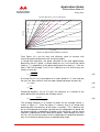
1
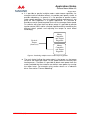
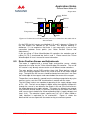
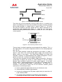
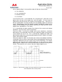
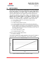
Application Notes Surface Mount Motor Kit August 2011 Marand Electric Machines Axial Flux Surface Mount Motor Kit For Solar Vehicle Applications Application Notes August 2011 MEM SCM01 (V 2) 1 of 32 Application Notes Surface Mount Motor Kit August 2011 CONTENTS 1. 1.1. 1.2. 1.3. 2. 3. 4. 5. 6. 7. 7.1. 7.2. 8. 8.1. 8.2. 8.3. 8.4. 9. 9.1. 9.2. 10. 11. 11.1. 12. 12.1. 12.2. 12.3. 12.4. 13. 14. 14.1. 15. 16. Important Safety Notices......................................................................3 Earthing.................................................................................................3 Voltage ..................................................................................................3 Magnetic Forces....................................................................................3 Warranty ...............................................................................................4 Limitations on Liability ..........................................................................4 Introduction ..........................................................................................6 Specification..........................................................................................7 Application Ideas...................................................................................9 Frameless Motor.................................................................................12 Magnet Rings ......................................................................................12 Stator...................................................................................................12 Motor Controller.................................................................................15 Interfacing a Controller.......................................................................16 Rotor Position Sensor and Adjustments.............................................18 Winding Temperature Sensing ...........................................................21 Using the Tritium WaveSculptor 22 Controller ..................................21 Motor Speed .......................................................................................22 Two Turns............................................................................................23 Air Gap ................................................................................................23 Motor Frequency ................................................................................23 Motor Current..................................................................................... 23 Two Turns............................................................................................24 Thermal Modelling..............................................................................25 Steady-State Modelling.......................................................................25 Transient Modelling ............................................................................26 Worked Example.................................................................................27 Comparison with test results..............................................................28 Motor Efficiency.................................................................................. 29 Inductor Rating ................................................................................... 31 Two Turns............................................................................................32 Contact and Further Information .......................................................32 Additional Important Information ......................................................32 MEM SCM01 (V 2) 2 of 32 Application Notes Surface Mount Motor Kit August 2011 1. IMPORTANT SAFETY NOTICES 1.1. Earthing The earthing of the motor is achieved through the axle, see Figure 1 below. This earthing connection should be capable of carrying the maximum possible short circuit current. This maximum current is possibly the short circuit current capability of the batteries. The connection must be capable of carrying this short circuit current for the worst case time for protection devices (fuses, circuit breakers, etc.) to operate. If it is considered likely that the protection devices may fail then the earth connection should be rated continuously for the worst case short circuit current. The insulation of the earth cable should be rated for the full voltage and expected temperature rise during a short to ground. Note power electronic devices normally fail short circuit, at least at first, therefore the motor controller cannot be relied upon to act as a fuse! If there is a short to the motor frame, the earth path is then through the bearings which is a poor electrical connection. There must be a warning placed on the wheel that power must be disconnected to the wheel before it is handled. 1.2. Voltage The motor is designed to operate at a nominal voltage of 150V. Please note these voltages can kill you. Work should only be carried out on these high voltage systems by suitably qualified personnel. 1.3. Magnetic Forces For the frameless motor it is necessary to handle magnetised rotors, and there are a number of associated hazards the user should be aware of. There is a large force of attraction between the two magnet rings, or between any magnetic material and a ring. The force between the two magnet rings is the worst case and is approximately given by: F= 6 .4 (25 × 10 −3 +d ) 2 (N) where d is the distance between the magnet rings in metres. Note, at 0mm this force is 10 kN or 1 tonne. Other hazards include the demagnetisation/magnetisation of analogue watches, credit cards, and a like. MEM SCM01 (V 2) 3 of 32 Application Notes Surface Mount Motor Kit August 2011 2. WARRANTY A warranty period of 6 months is applicable to the Kit Motor and commences from the date of shipment from Marand's premises. Marand warrants that the products will be free from defects in materials and workmanship for the warranty period. If any defects in materials or workmanship appear within the warranty period then, at its option, Marand will repair, replace or issue a refund based on an equitable adjustment in the price paid by you. Replacement components will be supplied on an exchange basis and may be either reconditioned or new. All defective components will be returned to Marand and will become the property of Marand. The warranties of Marand will only apply if: a) Marand is notified in writing within 14 days of discovery of any relevant defects; and b) Marand is satisfied that the motor has been properly assembled, installed and operated in accordance with any requirements set out in the documentation. In any case of warranty claim, only costs of materials and costs of hours of work carried out by Marand's service engineer will be borne by Marand. Warranty claims will be processed at Marand's premises only. The motor must be sent back to Marand's premises for servicing. Costs of transport of the Motor back to Marand will be borne by the purchaser. The warranties of Marand will not apply if the defect to the motor components arises from: a) Corrosion or adverse environmental conditions, such as exposure to extreme temperatures; or b) The use of power supplies or controllers which are not within the operational parameters for the motor or for failure in those power supplies/controllers; or c) Any re-configuration or modification by you or any other person of any of the motor components; or d) Any physical damage from Abuse or Misuse; or e) Any other extraneous circumstances outside Marand's control. Any cost associated with the detection or isolation of causes of nonperformance or malfunction due to any of the above circumstances will be borne by the purchaser. The stator is fitted with a non-reversible temperature sensing device which will record the maximum temperature the stator has reached in its lifetime. Removal of this device will void the warranty of the motor. 3. LIMITATIONS ON LIABILITY Marand's liability to the Customer arising in connection with the supply or use of the Products, including defective products whether under common law, equity or statute and whether direct or indirect is limited (to the extent permitted by law and not otherwise expressly provided for herein) to the cost of replacement of the Products or supply of equivalent products and without limitation excludes any liability for any incidental, consequential or indirect damages. MEM SCM01 (V 2) 4 of 32 Application Notes Surface Mount Motor Kit August 2011 Any remedy shall only be available to the Customer if the Products have been stored, maintained, installed, or operated by the Customer without damage or misuse and strictly in the manner prescribed by the Marand and in accordance with all applicable regulations and have not been repaired or altered without the expressed approval of Marand. To the extent permitted by law and except as provided herein, all implied conditions, warranties, and representations are hereby expressly negated and excluded. Marand shall not be liable for failure to perform or complete any of its obligations hereunder due to causes beyond the reasonable control of Marand. MEM SCM01 (V 2) 5 of 32 Application Notes Surface Mount Motor Kit August 2011 4. INTRODUCTION The motor kit is designed to allow solar racing teams to construct a brushless permanent magnet motor (axial field construction) that fits into a wheel of their choice. The motor kit consists of two rotors (which contain surface mounted magnets), a stator including position sensor and a set of three inductors. It is the responsibility of the purchaser to integrate the kit into a wheel. Marand can also supply a complete wheel as a turn key solution for solar car racing. These motors are supplied complete with rims suited to solar car racing tires and wiring harnesses, tested and ready to be bolted onto your car. Please contact Marand for further information. MEM SCM01 (V 2) 6 of 32 Application Notes Surface Mount Motor Kit August 2011 5. SPECIFICATION Motor Specifications1 Number of poles 40 Number of phases 3 Mass of frameless motor 10.45 kg Nominal speed2 111 rad/s Nominal torque3 16.2 Nm Magnetic gap – each side 1.75 mm Phase resistance 0.0575 Ω EMF constant – L-N RMS EMF/speed4 0.45 Vs/rad Torque constant per phase5 0.44 Nm/A Performance at Nominal Rating1 L-N RMS EMF4 50 V 12.3 A 25.9 W Eddy current loss 2.6 W 6 Windage 2.1 W Total loss 30.6 W Output power 1800 W Efficiency 98.3 % Nominal winding temperature rise 13 K Overload winding temperature rise7 70 K Maximum winding temperature 135 °C Maximum speed 157 rad/s 80 Nm 42 Nm 1.11 kg 0.00627 Ω 95 µH RMS phase current 5 Copper loss Absolute Maximum Ratings1 Maximum rated torque Maximum continuous torque8 3 x 100 µH Inductors Inductor mass 10 Inductor resistance Inductance 9 Table 1. Specifications and performance ratings MEM SCM01 (V 2) 7 of 32 Application Notes Surface Mount Motor Kit August 2011 Notes 1. Specifications, performance, ratings, price and availability can change without notice. Specifications, ratings, and performance quoted for whole of motor at 293 K (20°C) except where noted. 2. 111 rad/s ≈ 1060 rpm. 3. 16.2 Nm ≈ 11.9 lb ft ≈ 2294 oz in. 4. EMF sinusoidal. 5. Current sinusoidal and synchronised to rotor position. 6. Excludes external windage etc. 7. Total temperature rise having already temperature stabilised at the nominal rating and then run for a further 120 s at 80 Nm and 111 rad/s. 8. At 20°C Ambient temperature and nominal speed, maximum continuous torque is based on maximum continuous winding temperature rise. At higher ambient temperatures maximum torque will need to be de-rated. 9. Due to the low inductance of the motor, most motor controllers will require additional series inductance (3 will be supplied). 10. Inductor wired in parallel. MEM SCM01 (V 2) 8 of 32 Application Notes Surface Mount Motor Kit August 2011 6. APPLICATION IDEAS Below are a series of application ideas. It is not intended that these circuits are taken literally. All the circuits will require some experimentation before they can be used in a vehicle. The purpose of this section is to increase awareness of what is possible with the motor, not to provide complete solutions. The motor can be interfaced to a wide range of controllers; a typical installation is shown below. Also see section ‘Motor Controller’. Note, the diagram does not show user interface connections, soft start circuitry, or status information connections. The number and type of user interface and status connections will depend upon the controller. Whether soft start circuitry is required will also depend upon the controller. 3 × 100 µH Inductors + Motor Controller Motor 3 × Power Connections - Screen (Connected to GND at each end) 5 × Position Sensor Connections 2 × Temperature Connections Safety Earth Connection via Axle Figure 1. Power and control connections for a Motor Controller, note soft start circuitry not shown Motor controllers apply the battery voltage to the winding under PWM. The PWM ratio input is sometimes, confusingly, called the speed input, but it does not hold constant speed if the battery voltage or load torque change. To provide true speed holding, a feedback loop is required, as shown below. The desired speed input shown below could come from a potentiometer or a cruise control unit, for example: Speed Error Desired Speed (from user) + - Low Pass Filter Compensator PWM Ratio (To Motor Controller) Actual Speed (From Motor Controller) Figure 2. Block diagram of speed regulator for use with a motor controller that does not have speed regulation built in, but simply controls the PWM ratio MEM SCM01 (V 2) 9 of 32 Application Notes Surface Mount Motor Kit August 2011 Since the motor torque is approximately proportional to the RMS motor current it is possible to control the torque by controlling the current. Note, it is only practical to control the current on a per fundamental cycle basis using this technique, not on each PWM cycle. Current Error Desired Torque + (from user) - Low Pass Filter Compensator PWM Ratio (To Motor Controller) Actual Current (From Motor Controller) Figure 3. Block diagram of torque regulator for use with a motor controller that does not have torque regulation built in, but simply controls the PWM ratio Some motor controllers do not produce a signal proportional to RMS motor current; in these cases it is necessary to independently measure the current. The circuit shown below will require the filter in the torque regulator loop (see above) to be set so as to eliminate the fundamental phase ripple. About one fifth of the frequency of the fundamental for the lowest speed for normal running is a good starting point for finding the best setting for this cut-off frequency. Motor Power Connections 3 × AC/DC Current Transducers Max. Circuit Actual Current (To Torque Regulator) Figure 4. Measuring motor RMS current MEM SCM01 (V 2) 10 of 32 Application Notes Surface Mount Motor Kit August 2011 It is possible to parallel multiple motors under torque regulation, for example to drive individual wheels, to provide more power, and/or to provide redundancy. In general it is not possible to parallel motors under speed regulation, since the speed matching requirement is too great for most regulators in a typical application. It is possible to provide an overall speed regulator that uses the average motor speed. On vehicles with more than one driven wheel it is possible to provide traction control, ABS, and/or a limited slip differential by monitoring the different wheel speeds and adjusting the torque to each wheel accordingly. Desired Torque (from user) Motor, Controller, and Torque Regulator Motor, Controller, and Torque Regulator Figure 5. Paralleling multiple motors under torque regulation The main factor limiting the motor output is the torque; as the torque increases the motor gets hotter. As the speed increases relatively little heating occurs. Therefore it is possible to obtain more power from the motor, provided that the controller can deliver more power, by running the motor faster. For example using smaller wheels or a reduction drive. See section ‘Thermal Modelling’. MEM SCM01 (V 2) 11 of 32 Application Notes Surface Mount Motor Kit August 2011 7. FRAMELESS MOTOR The frameless motor allows the designer to choose their own requirements in coupling the motor to a wheel. The frameless motor consists of a two rotor rings and a stator (including the temperature sensor and position sensors). See drawing No. SCM01-0000-00 The parts supplied with a frameless motor are listed below: Part No. Qty Description Marking SCM01-0100-00 1 Stator nn-yy SCM01-0200-00 1 Magnet Ring (North) nn-yy SCM01-0300-00 1 Magnet Ring (South) nn-yy SCM01-0400-00 3 Inductors (1 x Red, 1 x White, 1 x Blue) nn-yy Documents Warning (x2), Drawings, App. Note Table 2. Supplied parts (Note: Markings are interpreted as nn = unique number, e.g. 01, and yy = two digit year of manufacture, e.g. 11 for 2011) When designing your own frame (or case) and axle, consideration and due care must be exercised to achieve the desired running performance. The stator is held stationary against the reaction torque of the two outer rotating rotor rings, while maintaining a constant air gap and concentricity. See drawings for dimensions of parts, air gap, and angular alignment of the two rings. 7.1. Magnet Rings The two rings supplied with the kit motor are different in that one has a north pole where the other has a south. This is indicated on one of the lugs of the magnet rings by way of an ‘N’ or an ‘S’ stamped into the steel. Care should be taken to use one North ring and one South ring in a motor assembly. It should be noted that at the correct air gap, there is a force of approximately 5 kN between the magnet rings. Therefore the motor frame must be strong enough under the influence of this force, as well as the dynamic wheel loads to maintain the air gap. It is also necessary to design assembly tools to allow the motor to be assembled and pulled apart in a controlled manner under these high forces. Please refer to section 1.3. Magnetic Forces. 7.2. Stator The stator will be provided with mounting holes drilled into the encapsulation, see the drawing No. SCM01-0000-00 for further details. A suitable ‘stator holder’ must be designed to hold the stator to the axle taking into account the torsional forces, concentricity requirements and rigidity. The stator includes a position sensor PCB to detect the relative position of the stator and the rotors. Depending on your motor controller, the angular alignment of the PCB with respect to the winding may require some fine adjustment. The PCB includes mounting slots which allow for 9 degrees of MEM SCM01 (V 2) 12 of 32 Application Notes Surface Mount Motor Kit August 2011 adjustment. The position sensor is factory set for use with a Tritium controller, however if you are using a different controller it may be necessary to adjust the position of the sensor board to achieve maximum efficiency. If this is the case, you will need to allow provision for the adjustments to the board location. This may be achieved by providing an access hatch in the motor frame. See ‘Rotor Position Sensor and Adjustments’ for more details concerning mounting and adjustment. The stator has four connections to be made, one for each of the three motor phases via M5 lugs protruding out of the stator encapsulation, and a plug connection to the PCB for the position sensor and thermistor information. Please note; the lugs protruding out of the stator are not designed to take any mechanical loads. As such, you will need to provide a mechanical fixing point inside your motor for your wires so as to eliminate any stresses on the lugs resulting from cable movement/vibration. The motor can produce significant thermal energy during high torque operation, as such, the frame of the motor needs to conduct the heat from inside the motor to the outside air. The thermal modelling of the motor given in ‘Thermal Modelling’ assumes a 2.5 mm thick aluminium frame. The standard stator is terminated in a ‘four turns per phase’ configuration. It is however possible to terminate the windings in a ‘two turns per phase’ configuration. If you require a motor which is terminated in a two turns per phase configuration please contact Marand, and make this clear when placing an order. The ‘two turns per phase’ configuration is non-standard. 7.2.1. Four Turns Most teams choose to wire the motor with four turns per phase. This is the assumption made in this application note unless noted. The winding is made up of 12 wires, three of these are terminated into lugs and brought out of the motor, three pairs are joined in series inside the stator, and the remaining three are joined inside the stator to form a star point. The motor and inductors are wired as shown below: Power Connection Lugs 1 Series Connection 2 3 Star Point 4 Motor 3 x Inductors Figure 6. Motor stator connections and corresponding inductor connections for four turns per phase MEM SCM01 (V 2) 13 of 32 Application Notes Surface Mount Motor Kit August 2011 7.2.2. Two Turns Occasionally teams may choose to wire the motor with two turns per phase to reduce the voltage, but at the expense of increased motor current. The winding is made up of 12 wires, six of these are terminated into three lugs and bought out of the motor, and the remaining six are joined inside the stator to form a star point. The motor and inductors, see ‘Inductor Rating’, are wired as shown below: Power Connection Lugs Parallel Connections 1 3 Star Point 2 4 Motor 3 x Inductors Figure 7. Motor stator connections and corresponding inductor connections for two turns per phase 7.2.3. Tritium WaveSculptor 22 The WaveSculptor 22 controller is able to operate at a lower inductance than some other controllers, in this case a four turn motor connection in combination with a two turn inductor connection can be used. See ‘Using the Tritium WaveSculptor 22 Controller’ for details. Power Connection Lugs 1 3 2 4 Series Connection Star Point Motor 3 x Inductors Figure 8. Motor stator connections and corresponding inductor connections for the Tritium Wave Sculptor 22 motor controller MEM SCM01 (V 2) 14 of 32 Application Notes Surface Mount Motor Kit August 2011 8. MOTOR CONTROLLER The motors are tested with a Tritium WaveSculptor 22 controller, but many other controllers will be suitable. The maximum efficiency is obtained when the controller applies a sinusoidal voltage synchronised to rotor position, because the motor’s EMF is sinusoidal. However controllers that apply a trapezoidal voltage can be used, see section ‘Motor Current’. To maximise the efficiency of the controller it is generally wise to pick a controller of the correct voltage rating and with a generous current rating. Most controllers will require additional line inductors because the synchronous inductance of the motor is approximately 20 µH. A set of three high efficiency 100 µH inductors are supplied (see section ‘Inductor Rating’). In general controllers run most efficiently with a minimal amount of PWM, i.e. flat out. Therefore it is best to pick the battery voltage close to the cruising speed, with a little in hand for overtaking (see ‘Motor Speed’). The main issues in interfacing a given controller are: The motor has three phases The motor requires the applied voltage to be synchronised with rotor position The position information is provided by three sensors with open collector outputs, that are suitable for operation in the range 5 to 15 V, see below for more information A thermistor (or negative temperature coefficient resistor) senses temperature and the controller must shut down when 408K (135°C) is reached, see below for more information The applied voltage needs to be sufficient for maximum speed (see ‘Motor Speed’) The applied current needs to be sufficient for maximum torque (see ‘Motor Current’) The fundamental frequency of the applied voltage needs to be sufficient for maximum speed (see ‘Motor Frequency’) The PWM frequency needs to be at least 8 kHz to use the 100 µH inductors if the controller modulates only one switch of the top and bottom pair at a time and at least 12 kHz if both switches are simultaneously modulated The controller must limit the maximum current supplied to the motor, see ‘Motor Current’ MEM SCM01 (V 2) 15 of 32 Application Notes Surface Mount Motor Kit August 2011 8.1. Interfacing a Controller A block diagram of the required connections is given in Figure 9 and a typical list of parts in addition to the motor and motor controller is given in Table 3. In Figure 9 terminations are given a ‘T’ number, and cables a ‘C’ number. Terminations may be either a solder joint or a plug and socket arrangement. The parts in the table are each given an item number. Note terminations T4 and T7 and cables C2 and C3 are inside the motor. The cables (C1-C3) are separately described below with reference to the parts table. Please note, with the kit motor, no cables or connectors are supplied. T4 T1 DC supply (from soft start) C1 Motor Controller & Inductors T2 Motor (T3) Motor Winding C2 Rotor Position Sensor PCB T5 Winding Temperature Sensor T7 (T6) C3 Figure 9. Block diagram of system connections (C = cable, T = termination) Item Description 1 Rotor Position Sensing PCB 2 8 way Molex MicroFit 3.0 Dual Row Crimp Housing, 43025-0800 3 1 1 6 way Molex MicroFit 3.0 Dual Row Crimp Housing, 43025-0600 4 Quantity 1 2 way Molex MicroFit 3.0 Dual Row Crimp Housing, 43025-0200 5 Molex MicroFit 3.0 Crimp Terminals, Female, 43030-0007 6 16 EPCOS 100 KΩ Thermistor, see section 8.3 Part No. B57550G104J 1 7 7 core, 7/0.2 stranded conductors (or 7/32AWG), 150°C+, Overall Screened 8 3 core 6 mm flexible cable, 150°C+, cannot have conductor coded as earth wire, see section 8.1.2 9 Standard Copper Crimp Lug, 6.0mm² M5 2 3 Table 3. Electrical parts list MEM SCM01 (V 2) 16 of 32 Application Notes Surface Mount Motor Kit August 2011 8.1.1. Cable 1 (C1) - DC Supply to the Controller (2 power wires) This cable should be sized to give an acceptable power loss for the length required. Typically this cable is made up from two single-insulated conductors that are inside an outer insulation layer. It is also important to follow the installation instructions given in the controller manual. 8.1.2. Cable 2 (C2) - Motor Controller Output to Motor Winding (3 power wires) This cable should be sized to take the maximum short term current of the motor and be temperature rated high enough to survive the self heating under high current operation in the high ambient temperature environment inside the wheel. The largest double-insulated cable that fits through the motor entry hole on the Marand wheel motor is item 8. Note the cable is to be clamped within the motor. Item 9 is suitable for T4. To assist in the quick removal of the wheel an optional connector (T3) may be used to provide a break in cable C2. Adding T3 also allows a different, perhaps thicker, cable to be used from the controller to T3. Note any additional connections made may result in extra voltage drops and thus impact the performance of the system. For the frameless motor C2 is not supplied and is difficult to source because most three core flexible cable have one core colour coded as earth (and therefore may not be used for a power connection). One possibility is to make the double-insulated cable up from three separate single-insulated cables with heat shrink tubing used for the outer layer of insulation. Additionally, the motor should be earthed to the battery negative through the axle, see ‘Important Safety Notice’. 8.1.3. Cable 3 (C3) - Motor Controller to Position Sensor PCB (7 signal wires + shield) Cable C3 is used to take the position and temperature information from the position sensor PCB back to the controller. Like cable C2 it may be advantageous to beak C3 to allow for quick removal of the motor by using optional termination T6. Unlike cable C2, there is no advantage in using a different cable for the two parts of C3. C3 is typically item 7 in the table. For the frameless motor, the same temperature considerations apply as to cable C2. The cable should again be clamped within the motor. T7 is the connection between cable C3 and the position sensor board. The connection is made via items 2 and 5. Cable C3 should also be clamped inside the motor to eliminate any stress on T7. The pin out for T7 on the position sensor PCB is given in Figure 10 below as viewed from the cable side of the connector. MEM SCM01 (V 2) 17 of 32 Application Notes Surface Mount Motor Kit August 2011 Hall #2 Hall #1 Hall #3 Temperature +12 V Temperature Shield GND Figure 10. Position Sensor PCB connection pin-out, as viewed from the cable side of the connector. On the PCB the Hall sensors are labelled A, B, and C, whereas in Figure 10 the Hall outputs are labelled #1, #2, and #3. This different labelling is deliberate, it is to emphasise that there is not necessarily a one to one connection between these points (see ‘Rotor Position Sensor and Adjustments’). If you are using a Tritium WaveSculptor 22 controller, the controller end of cable C3 (T5) is terminated into items 6 and 7. Please consult the Tritium WaveSculptor 22 user’s manual for more information. 8.2. Rotor Position Sensor and Adjustments The motor is supplied with a tested stator and position sensor, suitably aligned on the stator for the Tritium WaveSculptor 22 controller. The rest of this section is only directly relevant to the use of different motor controllers. The rotor position sensor PCB contains three Hall Effect devices used to sense the fringing magnetic field on the inside of one of the motor magnet rings. The top of the hall sensors should be located no more than 1 mm from the inside edge of the magnets and around about the centre of the magnet. The position sensor board is spaced from the winding encapsulation by nylon washers and as such the PCB should not be in contact with the stator. The Hall Effect Latches are capable of operating in the supply voltage range of 5V – 15V. The hall sensor output is digital; when the magnetic field passes through the sensor in one direction the output is 0V and if the field reverses the output becomes the supply voltage. The motor has 40 poles per magnet ring (20 North and 20 South), so for every revolution of the motor shaft each rotor sensor signal should have 20 corresponding High’s (supply voltage) and Low’s (0 V). The electrical signals repeat every 18°, this is often stated as “360° electrical is equivalent to 18° mechanical”. Figure 11 shows the idealised hall sensor output with the motor turning at a constant speed. MEM SCM01 (V 2) 18 of 32 Application Notes Surface Mount Motor Kit August 2011 Hall A Hall B Hall C Figure 11. Rotor position sensor digital signals The safest way to test the position sensing system once it is installed in the motor is by building a test circuit that simulates the signals normally provided by the motor controller, a suitable circuit is shown in Figure 12. The motor can then be rotated at constant speed and the signals observed on an oscilloscope and compared with Figure 11. Note the test circuit given contains no filtering and would therefore be unsuitable for use as the input to a real controller. +V Vcc 3 × 10 kΩ To oscilloscope 0V Hall A Hall B Hall C GND Figure 12. Test circuit for position sensors The next step is to align the position sensor board with the winding. This is a two stage process: first a coarse alignment and then a fine tuning alignment over a 9° arc. First, the motor controller should be connected to the motor as shown in Figure 1 and a 50 V, DC, current limited, power supply used instead of the battery (shown in the figure). The wiring order between the motor and controller is arbitrary, as explained below, but a good starting point is to wire Hall #1 to Hall A, etc., similarly for the power connections. The current limit should be set on the power supply to around 5 A. Set up an oscilloscope to display the current in motor winding A and the voltage between motor winding A and the DC power supply negative. A Hall type current probe is recommended because it will give a DC reading and it is isolated. An isolated voltage probe is recommended. Be careful not to introduce a short circuit or earth fault via the common, earthed, ground connections on oscilloscope inputs. Set the speed and regeneration on the user interface to zero. Select direction of rotation to be forwards. Increase the voltage on the DC power supply slowly (no more than 10 V per second) to 50 V. The speed setting should be very gradually increased whilst monitoring the motor current (there is no need to exceed 5 A). MEM SCM01 (V 2) 19 of 32 Application Notes Surface Mount Motor Kit August 2011 As the speed setting is increased the motor will do one of four things: turn clockwise, turn anticlockwise, become locked, or oscillate. If the desired result is not achieved: turn everything off, swap two of the power wires that go to the motor over, and start again. Do not swap the power wires that go from the DC supply to the controller over. There are six distinct combinations of wiring and only one will probably produce the desired result. Depending on where the board has been located with respect to the rotation of the winding it may also be necessary to swap two Hall sensor outputs over, although this is less likely. If it is not possible to obtain rotation then check all the current and voltage waveforms, you may have a fault in one phase. Once the motor is turning the voltage and current waveforms should be observed on an oscilloscope to fine tune the alignment angle of the position sensor board over the 9° arc. This is achieved by stopping the motor and adjusting the angle of the sensor board through the access hatch in the motor frame, see Frameless Motor’. Once the angle has been set correctly the current and voltage waveforms should look similar to those shown below. Some load applied by hand may be required to determine the true shape of the current waveform. The correct angle will also consume the minimum power to run the motor at a given operating point. Optimise the running of the motor for forwards running of the vehicle. The motor will run in reverse, but with slightly higher losses. Voltage (Line to DC negative) (Trapezoidal Waveform) Current Figure 13. Typical motor voltage and current waveforms when the sensor board has been adjusted to the correct position MEM SCM01 (V 2) 20 of 32 Application Notes Surface Mount Motor Kit August 2011 8.2.1. Tritium WaveSculptor 22 For the Tritium WaveSculptor 22 controller, the relationship between each hall-effect input and a motor output phase, as well as the polarity of the halleffect input signal does not matter. The WaveSculptor will detect these relationships when running its initial setup and configuration routine. The only requirement for these signals is that they have a fixed alignment (ideally 0° offset) with the zero-crossing point of the back EMF waveform of the motor. Use an oscilloscope to check this angle is close to 0° for your motor. See the WaveSculptor User’s Manual for further information. 8.3. Winding Temperature Sensing The stator has embedded in it a 100k NTC Thermistor for sensing the temperature of the motor during operation. This thermistor is connected to the PCB for easy connection to your motor controller. The sensor fitted (item 6 in Table 3) is a Epcos 100 KΩ Thermistor, B57550G104J (or equivalent), which has the following properties: The B value of the thermistor is 4085 K At room temperature (25°C, 298.15K) the resistance (R0) is 100 kΩ. See the thermistor Data Sheet for more information. The devices have a tendency to self heat, so it is necessary to limit the maximum current through them to 1 mA. Due to the lag between the increase in winding temperature and the decrease in resistance of the thermistor, it would be wise to set your motor controller to back the power off to the motor when the winding temperature is nearing its maximum temperature, say at 110°C. 8.4. Using the Tritium WaveSculptor 22 Controller Wiring details are available from the WaveSculptor web site and these documents note using the WaveSculptor in conjunction with a CSIRO motor. For this controller you would use a stator wired in the four turns configuration, and the inductors for two turns, because the controller is able to operate with a lower inductance provided that the inductors don’t saturate. Hence two-turn inductors, which have a quarter of the inductance but saturate at twice the current are the most suitable choice. The WaveSculptor controller is capable of higher current than is practical with the CSIRO motor, the problem is that the motor will overheat quicker then the temperature sensor can respond (this is due to the thermal time constant of the sensor). See ‘Motor Current’ for a discussion about overheating and current limits. MEM SCM01 (V 2) 21 of 32 Application Notes Surface Mount Motor Kit August 2011 9. MOTOR SPEED The motor EMF constant (induced voltage/speed) and winding impedance determines the motor speed at a given load torque for a given voltage applied by the motor controller. The controller adjusts the applied voltage up to a maximum determined by the battery voltage, or more precisely up to a maximum determined by the mean voltage at the controller input terminals. The maximum speed for a given battery voltage is also dependent on the controller and the inductors fitted. For example, the maximum speed depends upon the internal impedance of the controller, the losses in the controller, and whether it applies a trapezoidal or sinusoidal waveform. Therefore it is only possible to give a rough guide. A typical controller with: a mean voltage of 150 V DC on the controller input terminals, a sinusoidal waveform, full output voltage (speed set to max.), the recommended inductors fitted in series with each motor phase, the total impedance, per phase, of the wiring between the controller and the inductors and including the wiring between the inductors and the motor should be less than 20 mΩ of resistance and less than 10 µH of inductance, and with an external load torque of 16 Nm, the standard air gap of 1.75mm, will give a maximum speed of approximately: 120 rad/s (1150 rpm) The maximum speed will be roughly proportional to the mean DC voltage on the controller input. This linear relationship is shown in figure 14 below. Max Speed vs Voltage 1400 1200 Speed (RPM) 1000 800 600 400 200 0 0 20 40 60 80 100 120 140 160 Voltage Figure 14. Maximum motor speed as a function of voltage MEM SCM01 (V 2) 22 of 32 Application Notes Surface Mount Motor Kit August 2011 9.1. Two Turns If the motor is wired with two turns per phase (see ‘Frameless Motor’’), then the speed will be double for a given voltage. Note that changing the number of turns, and hence the EMF constant, also changes the torque constant (torque/ampere), see ‘Motor Current’. Please note, the maximum rated speed for the motors is 157 rad/s (1500 rpm). You will need to limit you motor speed to this if running two turns configuration. 9.2. Air Gap An alternate method of increasing the maximum speed attainable by the motor is to increase the magnetic gap between the rotor rings. This has the effect of flux weakening, changing both the motor speed and torque constants. However, it should be noted that changes in the magnetic gap will have an effect on the efficiency of the motor. 10. MOTOR FREQUENCY The fundamental frequency applied to each motor phase is proportional to speed. The fundamental frequency is 11. 3.183 Hz per rad/s or 0.3333 Hz per rpm. MOTOR CURRENT The temperature rise in the motor is related to the current flowing through the winding. The motors are fitted with a thermistor to measure the temperature of the winding, and should be shut down if it reaches 408 K or 135°C (see ‘Thermal Modelling’ below). Since there is a response time associated with the thermistor it is also necessary to limit the rate of rise of temperature by limiting the maximum current. The absolute maximum recommended RMS current is 5 times the nominal current (or 62A). These values correspond to a peak torque of 80 Nm, 5 times nominal torque, if a sinusoidal voltage synchronised to the rotor position is applied (since torque is proportional to the fundamental component of the current). The stator is fitted with a non-reversible temperature sensing device which will record the maximum temperature the stator has reached in its lifetime. Removal of this device will void the warranty of the motor. If the controller applies a trapezoidal voltage as opposed to a sinusoidal voltage, then an extra 5% RMS current is required for a given torque to account for the non-ideal waveform shape. Therefore the peak torque available from this type of controller is 76 Nm. Most controllers do not limit the RMS current; instead they limit the peak current. Neglecting peaks due to the action of the PWM, the ratio of RMS current to peak current is: 1:1.4 for a sinusoidal applied voltage and 1:1.8 for a trapezoidal applied voltage. MEM SCM01 (V 2) 23 of 32 Application Notes Surface Mount Motor Kit August 2011 Except when at maximum speed (PWM ratio = 1) there is also some extra RMS current required due to the PWM action of the controller. This is difficult to quantify as it is torque, speed, inductor, and controller dependent. For a typical controller with a PWM duty ratio of 0.86, a PWM frequency of 10 kHz, and the recommended inductors, at nominal torque and speed, a rough guide is to allow an extra: 0.1 A RMS and 1 A peak current. It is worth noting that only the fundamental frequency component of the current produces torque and the other frequency components only contribute to the losses in the motor, inductors, and controller. Therefore running with minimal PWM, i.e. speeds close to maximum speed, are advantageous in terms of losses. The controller also has switching losses when the PWM is enabled. Note that the limiting factor for peak current may not be the motor, but may be the controller or the batteries. 11.1. Two Turns If the motor is wired with two turns per phase (see ‘Frameless Motor’), then the current will be double for a given torque. Note that changing the number of turns and hence the EMF constant also changes the voltage constant (speed/volt), see ‘Motor Speed’. MEM SCM01 (V 2) 24 of 32 Application Notes Surface Mount Motor Kit August 2011 12. THERMAL MODELLING There are three temperatures of interest when modelling the motor: the ambient (Ta) or outside temperature, the magnet temperature (Tm), and the winding temperature (Tw). The winding temperature is the limiting factor and the maximum permissible is 408 K (135°C). The thermistor fitted to the winding should be monitored and the motor shut down if this temperature is reached. However it is still useful to estimate the winding temperature in advance to see if the motor is suitable for a given application. The following procedure should be used as a guide only, and to prevent motor burn out, the motor must be shut down when the temperature reaches the limit as indicated by the thermistor. There are two types of thermal modelling: steady-state and transient. As their names imply, steady-state modelling is when the motor speed and torque are constant, and transient modelling is when either of these quantities is varying. It is easier to work out the steady-state temperature than the transient temperature; hence the calculation of steady-state temperature is presented first. 12.1. Steady-State Modelling The procedure for calculating the steady-state winding temperature is iterative. To begin with you need the motor torque (τ) in Nm, the motor speed (ω) in rad/s, and an estimate of the steady state winding temperature (Tw) in K (say 323 K). The following set of equations is repeatedly solved until the winding temperature calculated does not change significantly, say less than 1K. This method gives relatively accurate results in the range of 0 – 40 Nm. 1. The magnet temperature is approximately half way between the winding and the ambient temperature, i.e.: Tm = 1 (Ta + Tw ) 2 (1) 2. The magnet remanence (B) is given by: B = 1.32 − 1.2 × 10 −3 (Tm − 293) (2) 3. The RMS per phase motor current (i) assuming a sinusoidal current aligned with the rotor position is given by: i = 0.561Bτ (3) 4. The per phase motor winding resistance (R) is given by: R = 0.0575(1 + 0.0039(Tw − 293)) (4) 5. The total motor winding i2R (copper) loss (Pc) is given by: Pc = 3i 2 R (5) 6. The total motor eddy current loss (Pe) is given by: MEM SCM01 (V 2) 25 of 32 ( Application Notes Surface Mount Motor Kit August 2011 −6 Pe = 2 9.602 × 10 ( Bω ) , Surface R (6) 7. The steady-state motor winding temperature depends on the thermal resistance of the motor frame, which is estimated to be 0.455 K/W. Therefore the winding temperature is given by: Tw = 0.455( Pc + Pe ) + Ta (7) For example, at nominal torque (16.2 Nm) and nominal speed (111 rad/s) in a 293 K ambient, the steady-state winding temperature is 306 K. 12.2. Transient Modelling An easy, but approximate, technique for finding the winding temperature under transient conditions is to approximate the transient load at an equivalent steady-state value (to allow the losses to be calculated) and then to approximately calculate the transient temperature rise above ambient. The validity of this transient calculation can be assessed by calculating the difference in the steady-state and extremes of transient temperatures. If this difference is less than 50 K then the calculated absolute temperatures, in K, are probably within 5%. The calculation assumes that the transient condition can be broken into a sequence of steps or intervals and that the sequence repeats for ever, i.e. the calculated temperature rise at the end of the last interval is the temperature rise at the start of the first interval. 1. There are essentially two techniques to work out an equivalent steadystate temperature for the winding. If the transient event is a one off occurrence in an otherwise steady operation, then the equivalent steady-state temperature is simply the temperature given by equations (1) to (7) with the speed and torque as for the steady operation. If the transient event is cyclic, then the equivalent steady-state temperature is given by finding the RMS values of speed and torque and using these values in the steady-state calculation. If in doubt, use the RMS values. 2. Use the value of Tw calculated in step 1 to calculate B and R (equations (2) and (4) respectively). 3. Divide the transient cycle of speed and torque into n intervals. For each interval, j, the time the interval lasts for, tj, the speed, ωj, and the torque, τj, are required. Calculate Pcj and Pej (equations (5) and (6) respectively) for each interval. 4. The thermal time constant is the product of the thermal resistance and thermal capacitance and is 652.9 s. Using the thermal time constant, calculate the exponential coefficient, αj, for each interval: −t j αj =e 652.9 (8) 5. Calculate the steady-state temperature rise, βj, over ambient, for each interval: MEM SCM01 (V 2) 26 of 32 Application Notes Surface Mount Motor Kit August 2011 β j = 0.452( Pcj + Pej ) (9) 6. Formulate the α matrix m: 1 − α 2 m= 0 0 0 0 L 1 0 1 L L − α3 0 O O L − αn − α1 0 0 1 (10) 7. Formulate the β row vector v: v = [ β1 (1 − α 1 ) L β n (1 − α n ) ] (11) 8. Find the winding temperature rise above ambient (row vector θ) at the end of each interval, assuming the sequence of intervals repeats ad infinitum by solving the matrix equation mθ T = v T . For example if the motor is run at its nominal rating until temperature equilibrium is reached and then it is run at 80 Nm for 120 s, the final temperature rise over ambient will be 70 K (see ‘Worked Example’ below). 12.3. Worked Example The motor thermal calculations are available as a Zipped Microsoft Excel (Office 2003 version) file on the Marand website. However, it is still useful to run through the calculations. First a steady-state calculation for the Surface motor running at their nominal rating of 16.2 Nm and 111 rad/s in an ambient of 293 K. The results from iterating equations (1) to (7) are given below. Tm = 300 K B = 1.312 T i = 11.9 A R = 0.0605 Ω Pc = 25.8 W Pe = 3.37 W Tw = 306.3 K These numbers are easily verified using equations (1) to (7) to show that the values do not significantly change with another iteration. If the motor having first temperature stabilised under nominal load, as above, is run for 120 s at 5 times nominal torque (i.e. maximum torque of 80 Nm) at nominal speed (111 rad/s) in an ambient of 293 K, then this overload and the subsequent cooling of the motor may be modelled by dividing this load sequence into 5 intervals for example. In the example below, the first interval is at nominal torque, the second is the overload and the next three intervals are again at nominal torque to show how quickly the motor cools. Note, the sequence (of overload followed by cooling) and number of intervals (provided that the total time at a given torque is the same) are not important. However, it should be noted that the sequence is MEM SCM01 (V 2) 27 of 32 Application Notes Surface Mount Motor Kit August 2011 cyclic and therefore the whole of the overload and cooling down times must be completely modelled. In summary the example sequence of intervals is: 1. Running at 16.2 Nm for 720 s 2. The overload at 80 Nm for 120 s 3. Cooling at 16.2 Nm for 720 s 4. Cooling at 16.2 Nm for 720 s 5. Cooling at 16.2 Nm for 720 s The values of B and R found above in the steady-state example are used in the transient calculation, since this transient sequence is predominantly the nominal torque of 16.2 Nm. i1 = 11.565, i2 = 57.110, i3, i4, i5 = 11.565 A Pc1 = 30.192, Pc2 = 736.289, Pc3, Pc4, Pc5 = 30.192 W Pe1, Pe2, Pe3, Pe4 = 2.546 W α1 = 0.576, α2 = 0.912, α3, α4 = 0.576 β1 = 14.896, β2 = 336.170, β3, β4 = 14.896 K θ1 = 15.6, θ2 = 69.4, θ3 = 33.0, θ4 = 20.9, θ5 = 16.9 K From the temperature rise above ambient results it is seen that the maximum winding temperature for the Surface motor is 293 + 69.4 = 362.4K and that the motor quickly returns to its normal temperature for nominal load, i.e. 293 + 15.6 = 308.6 K. 12.4. Comparison with test results Testing has been conducted on the motor to verify the accuracy of the steady state and transient thermal models. The results have shown that the steady state calculation is accurate to within 5% in the torque range of 0 – 40Nm. Beyond 40 Nm, the calculation will understate the winding temperature. The transient model was tested by running the motor under load through a speed-torque profile for 40mins. An idealised speed-torque profile was run through the calculation to generate the winding temperature at the end of each of the torque intervals. The calculated temperature was within 5% of the actual winding temperature for the entire test. The results are shown below. Transient Thermal Model Comparison to Measured Results 120 144 132 120 108 80 96 84 60 72 60 40 48 36 20 Motor Temperature (°C) Torque (Nm) & Speed (rad/s) 100 TORQUE (Nm) Torque Approximation SPEED (rad/s) Speed Approximation MOTOR TEMPERATURE (°C) Temperature Approximation 24 12 0 0 0 500 1000 1500 2000 2500 Cumulative Time (s) Figure 15. Comparison of transient thermal model to test results MEM SCM01 (V 2) 28 of 32 Application Notes Surface Mount Motor Kit August 2011 13. MOTOR EFFICIENCY Most of the information needed to calculate motor efficiency is given in the ‘Thermal Modelling’ section, i.e. the copper loss, Pc, and the eddy current loss, Pe. The missing calculations are the motor’s internal and external windage and the bearing losses. The external windage depends on how the motor is attached to the wheel, the wheel tyre it is attached to, and the geometry of the wheel spats. The bearing loss depends on the loads applied to the bearings. The external windage and bearings may be approximately measured by running a wheel without the motor attached under load. Because it is difficult to theoretically determine the external windage and the bearing losses, and because it is a debatable point as to whether these losses should be counted as motor or wheel losses (the wheel requires sides and bearings regardless of the motor!), both these losses are neglected in the following calculation of motor efficiency. The internal windage, Pw, is given by: Pw = 170.4 × 10 −6 ω 2 (12) The motor efficiency, η, in % is: η= τω τω + Pc + Pe + Pw (13) × 100 For all parts of the motor at 273 K with a load, τ, of 16.2 Nm at a speed, ω, of 111 rad/s the efficiency is 98.3%. Since the copper loss is typically much bigger than the eddy current loss and the windage loss and the efficiency changes little with temperature, the loss may be approximated as: η≈ τω τω + 0.1765τ 2 × 100 = ω × 100 ω + 0.1765τ (14) Note, the above equations are based on the copper losses calculated for steady-state operation at nominal load in Section 12.3. The copper loss is therefore a little higher than the losses given in the Specifications. This is because the Specifications are given for the whole motor at 293 K, not the raised winding temperatures of 306 K that result from continuous nominal load running (see ‘Thermal Modelling’). Therefore the efficiency can be approximately calculated as a function of speed and torque and the result is shown in Figure 16. MEM SCM01 (V 2) 29 of 32 Application Notes Surface Mount Motor Kit August 2011 Aproximate Motor Efficincy Contours (Single Machine) 35 90% 92% 94% 95% 30 91% 89% 65% 93% 96% 25 Torque (Nm) 97% 20 98% 15 10 99% 5 0 0 250 500 750 1000 1250 1500 1750 Speed (RPM) Figure 16. Approximate efficiency contours From Figure 16 it can be seen that efficiency tends to increase with increasing speed and decrease with increasing torque. In steady-state operation, the power delivered to the road approximately determines the car’s speed. A simple model of a car is to assume that speed cubed (ν 3) is proportional to the power delivered to the road (Pd). If the car takes 1798.2 W to propel it at 27.8 m/s (100 km/h or 61.2 miles/h) then the velocity is given by: ν=3 Pd 0.08386 (15) Assuming that 27.8 m/s corresponds to a motor speed of 111 rad/s and that the tyres are 100% efficient, then the motor speed and torque are given by: ω = 3.993ν (16) Pd (17) τ= ω Combining equations (14) to (17) gives the efficiency as a function of the power delivered to the road for the example vehicle. η≈ 912.25 9.1225 + 0.01935( Pd ) 1 (18) 3 The resulting efficiency as a function of power for the example vehicle is shown in Figure 17. From the figure it is obvious that at all steady-state operating points the efficiency of the motor is excellent. This is because the losses are proportional to torque squared and are independent of speed, but the torque required is proportional to power to the two thirds, and the speed required is proportional to the cubed root of power. Motor designs that have iron loss do not have the feature of loss independent of speed and therefore they do not hold their efficiency over a wide operating range. MEM SCM01 (V 2) 30 of 32 Application Notes Surface Mount Motor Kit August 2011 Motor efficiency as a function of power 100.0 99.5 99.0 Efficiency (%) 98.5 98.0 97.5 97.0 0 500 1000 1500 2000 Power (W) Figure 17.Approx steady-state efficiency as a function of power for example vehicle 14. INDUCTOR RATING Most motor controllers require some additional series inductance, typically at least 100 µH per phase is required (see Figure 1 and section ‘ Motor Controller’). Specially designed low loss inductors are supplied with the motor kit. The nominal ratings of each inductor, connected in series are: Inductance: 95 µH Resistance: 12 mΩ Weight: 1.11 kg Temperature limit: 393 K (120°C) Maximum peak current before saturation: 55 A (Four Turns Configuration) Maximum peak current before saturation: >80 A (Two Turns Configuration) The thermal rating of the inductors is designed to be better than the thermal rating of the motor. Therefore provided that the motor and the inductors are in a similar ambient temperature, there is no need to measure the temperature of the inductors. There are two loss components in each inductor: copper loss (Pci) and yoke loss (Pyi). These losses are given by: Pci = 12 × 10 −3 i 2 (19) Pyi ≈ 2.7 × 10 −6 i 3 f (20) Where; f is the fundamental frequency of excitation, see ‘Motor Frequency’. Note, the yoke loss is given only approximately since a more accurate calculation requires a Fourier analysis of the current waveform. At the nominal rating of 16.2 Nm and 111 rad/s in an ambient of 293 K, the total loss in each inductor is 4.88 W. Since these losses are so low, it is normally reasonable to neglect inductor losses. MEM SCM01 (V 2) 31 of 32 Application Notes Surface Mount Motor Kit August 2011 14.1. Two Turns If the motor has two turns then the inductors should use a parallel connection, see ‘Frameless Motor’. For this connection the current rating of the inductors is doubled, but their inductance and resistance are reduced by a factor of four. The loss figures given above, (19) and (20) are for the four turn connection. Therefore, if using two turns remember to scale the current down by a factor of two before using (19) and (20). 15. CONTACT AND FURTHER INFORMATION Please direct all enquires to: Marand Precision Engineering Pty Ltd 153 Keys Rd Moorabbin Victoria Australia 3198 Tel.: +61 3 8552 0600 Email: [email protected] 16. ADDITIONAL IMPORTANT INFORMATION Copyright © Marand 2011 Specifications, performance, and price can change without notice The term ‘vehicle’ is used to encompass any use of the motors, for example in a solar and/or battery powered car, boat, or bicycle. Information with regard to Tritium is supplied as a guide only; please refer to Tritium for more complete information. WaveSculptor is a trademark of Tritium, no warranties are implied by providing you with this information. MEM SCM01 (V 2) 32 of 32