1
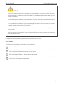
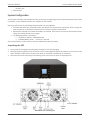
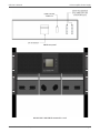
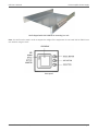
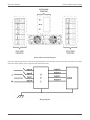
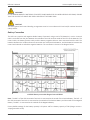
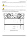
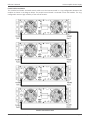
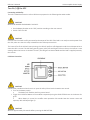
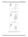
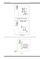
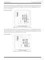
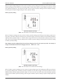
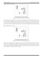
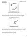
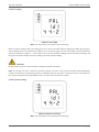
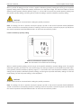
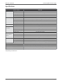
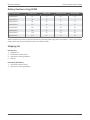
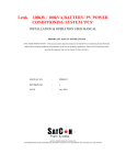
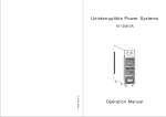
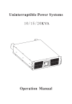
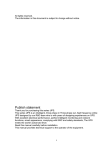
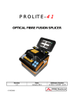
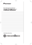
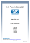
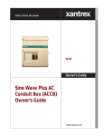
R90 Online UPS
20kVA Model
User & Installation Manual
www.xpcc.com | © 2015 Xtreme Power Conversion Corporation. All rights reserved. (Rev 8/19/15)
R90 User’s Manual
Uninterruptible Power Supply
Table of Contents
Introduction.................................................................................................6
Product Description..................................................................................... 6
Main Features..................................................................................................................................6
System Configuration...................................................................................7
Unpacking the UPS..........................................................................................................................7
Installation Notes.......................................................................................................................... 10
External Protective Devices...........................................................................................................10
Power Cables.................................................................................................................................11
Power Cables Connection............................................................................................................. 11
Battery Connection....................................................................................................................... 13
UPS Multi-Module Installation.......................................................................................................15
Operation...................................................................................................18
Operation Modes..........................................................................................................................18
Turn On / Off the UPS....................................................................................................................19
Communication Port Definitions (RS232, RS485)..........................................................................25
The Display....................................................................................................................................26
Display Messages.......................................................................................................................... 41
Options..........................................................................................................................................43
Troubleshooting.........................................................................................44
Batteries.....................................................................................................45
Replacing The Battery....................................................................................................................45
Specifications.............................................................................................46
Battery Runtimes Using EBP32...................................................................47
Shipping List.............................................................................................. 47
Obtaining Service.......................................................................................48
Xtreme Power Conversion Limited Warranty..............................................49
Xtreme Power Conversion Corporation
Page 2
R90 User’s Manual
Uninterruptible Power Supply
Thank you for selecting this uninterruptible power supply (UPS). It provides you with protection for connected
equipment. Please read this manual before installing the R90-20KVA model as it provides important information
that should be followed during installation and maintenance of the UPS and batteries, allowing you to correctly
set up your system for the maximum safety and performance. Included is information on customer support and
service, if it is required. If you experience a problem with the UPS, please refer to the Troubleshooting section in
this manual to correct the problem. If the problem is not corrected, please collect information so that the Technical
Support personnel can more effectively assist you.
Xtreme Power Conversion Corporation
Page 3
R90 User’s Manual
Uninterruptible Power Supply
Important Safety Instructions: (Save These Instructions)
CAUTION! (UPS having Internal Batteries): Risk of electrical shock – Hazardous live parts inside this unit are energized from the battery supply even when the input AC power is disconnected.
CAUTION! (No User serviceable Parts): Risk of electrical shock, do not remove cover. No user serviceable parts
inside. Refer servicing to qualified service personnel.
CAUTION! (Non-isolated Battery supply): Risk of electric shock, battery circuit is not isolated from AC input, hazardous voltage may exist between battery terminals and ground. Test before touching.
WARNING! (Fuses): To reduce the risk of fire, replace only with the same type and size of fuse.
WARNING! Unit intended for installation in a controlled environment.
CAUTION! Do not dispose of batteries in a fire, the battery may explode.
CAUTION! Do not open or mutilate the battery, released electrolyte is harmful to the skin and eyes.
CAUTION! A battery can present a risk of electric shock and high short circuit current. The following precaution
should be observed when working on batteries:
• Remove watches, rings or other metal objects.
• Use tools with insulated handles.
To reduce the risk of electric shock, disconnect the UPS from the main supply before installing a computer interface signal cable. Reconnect the power cord only after signaling interconnections have been made.
Servicing of batteries should be performed or supervised by personnel with knowledge of batteries and the required precautions. Keep unauthorized personnel away from batteries.
These UPS units are extremely heavy. Caution should be taken in moving and positioning equipment.
The instructions contained within this safety manual are deemed important and should be closely followed at all
times during installation and follow-up maintenance of the UPS and batteries.
Xtreme Power Conversion Corporation
Page 4
R90 User’s Manual
Uninterruptible Power Supply
CAUTION
The unit has a dangerous amount of voltage. If the UPS indicator is on, the unit’s outlets may have a
dangerous amount of voltage even when not plugged into the wall outlet because the battery may continue to supply power.
Care should be taken to undertake installation indoors, free from electrically-conductive particles which
are under temperature and humidity control, in order to reduce the risk of electric shock.
It is best to disconnect the device using the power supply cord. Ensure that the equipment is placed in
a position near the outlet where easily accessible.
Except for replacing the batteries, all servicing on this equipment must be carried out by qualified service personnel.
Before conducting any maintenance, repair, or shipment, first ensure that everything is turned off completely and disconnected.
For additional safety instructions, please use the Safety Manual as a reference.
Special Symbols
The following symbols used on the UPS warn you of precautions:
RISK OF ELECTRIC SHOCK - Please observe the warning that a risk of electric shock is present
CAUTION: REFER TO OPERATOR’S MANUAL - Refer to the operator’s manual for additional information,
such as important operating and maintenance instructions.
SAFE GROUNDING TERMINAL - Indicates primary safe ground
Please do not discard of the UPS or the UPS batteries as the UPS may have valve-regulated lead-acid batteries. Please recycle batteries appropriately.
Xtreme Power Conversion Corporation
Page 5
R90 User’s Manual
Uninterruptible Power Supply
Introduction
The information provided in this manual covers three-phase 20kVA uninterruptible power systems, its basic functions, operating procedures, options available and emergency situations. It also includes information on how to
ship, store, handle, and install the equipment. Only detailed requirements of the UPS units are described herein,
and installation must be carried out in accordance with this manual. Electrical installation must also carefully
follow local legislation and regulations. Only qualified personnel should conduct these installations as failure to
acknowledge electrical hazards could prove to be fatal.
Product Description
Many different kinds of sensitive electrical equipment can be protected by an Uninterruptible Power Supply (UPS)
including computers, workstations, process control systems, telecommunications systems, sales terminals, other
critical instrumentation, etc. The purpose of the UPS is to protect these systems from poor quality utility power,
complete loss of power, or other associated problems.
Electrical interference exists in many forms, causing problems in AC power, from lightning, power company accidents and radio transmission motors, air conditioners, and vending machines. Protection of sensitive electrical
equipment is vital to protect against power outages, low or high voltage conditions, slow voltage fluctuations,
frequency variations, differential and common-mode noise, transients, etc.
To prevent power line problems from reaching critical systems causing damage to software, hardware, and equipment malfunctions, the UPS maintains constant voltage, isolating critical load output and cleaning the utility AC
power.
Main Features
This is a three phase input / three phase output high-frequency online UPS. The UPS protects against power failures, power sag, power surge, under-voltage, over-voltage, line noise, frequency variations, switching transients,
and harmonic distortion which can all cause critical problems to supported sensitive electronic equipment in the
market today.
Functions and Features
• 3 phase input/output high-density UPS
• Digital Control
o The UPS is controlled by Digital Signal Processor (DSP) which increases reliability, performance,
self-protection, self-diagnostics, etc.
• Modular Design
• Battery Configuration
o The battery voltage can be configured based on needs
• Charging Configuration
o The charging current can be customized to meet site requirements
• Intelligent Charging Method
o 1st stage = high current constant current charging to restore batteries to 90% capacity
o 2nd stage = constant current charging to assure batteries remain fully charged
o 3rd stage = float charge
The 3-stage charging method extends the life of the batteries and guarantees rapid recharging
• LCD Display
o Both LED and LCD displays allow for ease of use and availability of critical UPS status and operational parameters, including: input/output voltage, frequency and load %, battery %, ambient temXtreme Power Conversion Corporation
Page 6
R90 User’s Manual
Uninterruptible Power Supply
perature, etc.
• EPO Function
System Configuration
The UPS device and the internal batteries make up the system. Depending on the site and load requirements of the
installation, certain additional options are available for the solution.
Planning a UPS system, the following should be taken into consideration:
• The total demand of the protected system shall dictate the output power rating (VA). Allow a margin for
future expansion or calculation inaccuracies from measured power requirements.
• Backup time required will indicate the battery size needed. If the load is less than the UPS nominal power
rating, then actual backup time is longer.
• The following options are available:
o Connectivity Options –SNMP/WEB card
o Extended Battery Packs - minimum 1 required
See the Specification section of this manual for additional model information.
Unpacking the UPS
1. Do not lean the UPS against anything when moving it out of the packaging.
2. Check the physical appearance of the UPS to see if it was damaged during transportation. Do not switch on the
UPS if damage is found. Please contact your dealer or distributor immediately for assistance.
3. Check the accessories according to the packing list to assure that you have all required pieces.
R90-20K front view
R90-20KVA rear view diagram
Xtreme Power Conversion Corporation
Page 7
R90 User’s Manual
Uninterruptible Power Supply
EBP32 rear panel
R90-20K UPS + R90-EBP32 mounted in a rack
Xtreme Power Conversion Corporation
Page 8
R90 User’s Manual
Uninterruptible Power Supply
Shelf shipped with UPS & EBP32 for mounting in a rack
Note: this shelf must be used in order to support the weight of the equipment. Do not install UPS or EBP32 into a
rack without using this shelf
Front panel
Xtreme Power Conversion Corporation
Page 9
R90 User’s Manual
Uninterruptible Power Supply
Installation Notes
• Place the UPS in a clean, stable environment, avoiding vibration, dust, humidity, flammable gas and liquid,
corrosive objects, etc. Check the operating temperature of the room where the UPS is being installed to
assure it is within range of UPS specification.
• Batteries should be installed in an environment where the temperature is within the required specifications of the product. Temperature is a major factor in determining battery life and capacity. Normal battery
installation requires the temperature be maintained from 15°C to 25°C. Keep batteries away from heat
sources and main air ventilation areas.
WARNING!
Typical battery performance data is quoted for an operating temperature between 20°C and 25°C. Operating above
this range will reduce the battery life while operation below this range will reduce the battery capacity.
If the equipment is not to be installed immediately, it must be stored in a room so as to protect it against excessive
heat and humidity sources.
CAUTION!
An unused battery must be recharged every 6 months. Temporarily connecting the UPS to a suitable AC source and
activating the UPS for the time required to recharge the batteries is required.
• To monitor the UPS with the software, simply connect the RS232 cable to the UPS and to a computer.
External Protective Devices
For safety reasons, it is necessary to install an external circuit breaker at the input AC utility and to the battery.
External Battery
The UPS and its associated batteries are protected against the effect of over-current through a DC compatible
thermo-magnetic circuit breaker located close to the battery.
UPS Output
Any external distribution board used for load distribution shall be fitted with protective devices so as to avoid the
risk of UPS overload.
Over-Current Protection
A protection device shall be installed at the distribution panel of the incoming utility power, and should identify
the power cables current capacity as well as the overload capacity of the system.
CAUTION!
Select a thermo magnetic circuit-breaker with an IEC 60947-2 trip curve C (normal) for 125% of the current as listed
below. 40A Input Circuit Breaker required
Xtreme Power Conversion Corporation
Page 10
R90 User’s Manual
Uninterruptible Power Supply
Power Cables
The cable design shall comply with the voltages and currents provided in this section, and in accordance with local
electrical codes.
WARNING!
UPON STARTING, PLEASE ENSURE THAT YOU ARE AWARE OF THE LOCATION AND OPERATION OF THE EXTERNAL
ISOLATORS WHICH ARE CONNECTED TO THE UPS INPUT/BYPASS SUPPLY OF THE UTILITY DISTIRBUTION PANEL.
CHECK TO SEE IF THESE SUPPLIES ARE ELECTRICALLY ISOLATED, AND POST ANY NECESSARY WARNING SIGNS TO
PREVENT ANY INADVERTENT OPERATION
Cable Sizes
UPS MODEL
R90-20K
AC INPUT
8 awg
CABLE SIZES (THHW wiring at 75°C)
AC OUTPUT
DC INPUT
8 awg
6 awg
GROUNDING
8 awg
CAUTION!
Protective earth ground cable: connect each cabinet to an earth ground, following the shortest route possible.
WARNING!
FAILURE TO FOLLOW ADEQUATE GROUNDING PROCEDURES MAY RESULT IN ELECTROMAGNETIC INTERFERENCE
OR IN HAZARDS INVOLVING ELECTRICAL SHOCK AND FIRE.
Power Cables Connection
After the equipment has been properly positioned and secured, connect the power cables as described below.
Verify the UPS is totally isolated from its external power source and all circuit breakers to the UPS are open. Check
to see that everything is electrically isolated, and post any necessary warning signs to prevent inadvertent operation of the breakers.
Xtreme Power Conversion Corporation
Page 11
R90 User’s Manual
Uninterruptible Power Supply
Power cable connection diagram
Select the appropriate power cable size, paying attention to the diameter of the connection terminal of the cable,
which should be greater than or equal to the connection posts.
Wiring diagram
Xtreme Power Conversion Corporation
Page 12
R90 User’s Manual
Uninterruptible Power Supply
WARNING!
IF THE LOAD EQUPMENT IS NOT READY TO ACCEPT POWER WHEN THE UPS INSTALLATION IS OCCURING, ENSURE
THAT THE UPS OUTPUT CABLES ARE SAFELY ISOLATED AT THE CABLE ENDS.
CAUTION!
The earth ground and neutral bonding arrangement must be in accordance with local and/or national electrical
code practices.
Battery Connection
The UPS has a positive and negative double battery framework using a total of 32 batteries in series. A neutral
cable is retrieved from the joint between the cathode of the 16th and the anode of the 17th of the batteries. The
neutral cable, the battery positive cable, and the battery negative cable are then connected with the UPS. The
batteries between the anode and neutral connection are called positive batteries, and the batteries between the
neutral and cathode are called the negative batteries. The connection is shown in the diagram below.
± 192VDC battery connection diagram internal EBP32
Note: The BAT + of the UPS Connection Terminals is connected to the anode of the Positive Battery. The BAT – of
the UPS Connection Terminals is connected to the cathode of the Positive Battery and the anode of the Negative
Battery. The BAT – is connected to the cathode of the Negative Battery.
Factory default settings for the battery quantity is 32 pieces and for a battery capacity of 7AH (charger current =
1A programmable to 6A)
Xtreme Power Conversion Corporation
Page 13
R90 User’s Manual
Uninterruptible Power Supply
Note: Optional 3rd party battery configurations of ±192VDC/±204VDC/±216VDC/±240VDC can be used and are
available.
CAUTION!
Ensure correct polarity of the battery string series connection (i.e. inter-tier and inter block connections are from
(+) to (-) terminals. DO NOT mix batteries with different capacity or different brands, or new or old batteries.
WARNING!
ENSURE CORRECT POLARITY OF STRING END CONNECTIONS TO THE BATTERY CIRCUIT BREAKER, AND FROM THE
BATTERY CIRCUIT BREAKER TO THE UPS TERMINALS (I.E. (+) TO (+) / (-) TO (-)). DISCONNECT ONE OR MORE
BATTERY CELL LINKS IN EACH TIER. DO NOT RECONNECT THESE LINKS AND DO NOT CLOSE THE BATTERY CIRCUIT
BREAKER UNLESS ALL CONNECTIONS ARE PROPERLY CHECKED AND APPROVED.
R90-20K to EBP32 battery connection
Xtreme Power Conversion Corporation
Page 14
R90 User’s Manual
Uninterruptible Power Supply
UPS Multi-Module Installation
The basic installation procedure for a parallel system consisting of two or more R90-20KVA modules is that same
as that of a single module. The following provides installation procedures related to a parallel system.
Cabinet Installation
Connect all R90-20KVA UPS required in the parallel system as shown in the diagram below.
Note: If installing 5-6 units in parallel, remove the jumper cap J30 on the control inspection board (MHTBJHR1CU04 in all UPS to be connected in parallel. If installing 7-10 units in parallel, remove the jumper cap J30/J31
on the control inspection board (MHTBJHR1CU04 in all UPS to be connected in parallel. Make sure that each UPS
input breaker is in the “OFF” position and there is no output from any UPS connected. The battery strings can be
connected separately or in parallel.
WARNING!
MAKE SURE THE N, A(L1), B(L2), AND C(L3) WIRING IS CORRECT, AND THAT GROUND IS CONNECTED.
Xtreme Power Conversion Corporation
Page 15
R90 User’s Manual
Uninterruptible Power Supply
Parallel Cable Installation
The shielded and double insulated control cables must be interconnected in a ring-configuration between UPS
modules as shown in the diagram below. The parallel control board is mounted in each UPS module. The ringconfiguration ensures high-reliability of the control function.
Parallel connection of UPS
Xtreme Power Conversion Corporation
Page 16
R90 User’s Manual
Uninterruptible Power Supply
Remote Emergency Power Off (EPO) for Parallel Systems
EPO for parallel systems must be connected in parallel and installed as shown below. Once the EPO function of one
of the UPS in the parallel system is activated, the UPS will send out a remote command and shut down the other
UPS’s in the parallel system.
CAUTION!
The remote emergency kill switch must be voltage-free and “normally open”.
EPO connections for parallel systems
Xtreme Power Conversion Corporation
Page 17
R90 User’s Manual
Uninterruptible Power Supply
Requirements for a Parallel System
A group of parallel UPS modules behave as one large UPS system with the advantage of presenting higher reliability. In order to assure that all modules are equally utilized and comply with relevant wiring regulations, please
follow the requirements below.
1. All UPS modules must be of the same rating and be connected to the same bypass source.
2. The Bypass and Utility input sources must be referenced to the same neutral potential.
3. The outputs of all the UPS modules must be connected to a common output bus.
4. The length and specification of power cables including the bypass input cables and the UPS output cabinets should be the same size. This facilitates load sharing when operating in bypass mode.
5. Up to 10 UPS modules may be paralleled with common battery if desired
Note: If installing 5-6 units in parallel, remove the jumper cap J30 on the control inspection board (MHTBJHR1CU04 in all UPS to be connected in parallel. If installing 7-10 units in parallel, remove the jumper cap J30/J31 on
the control inspection board (MHTBJHR1CU04 in all UPS to be connected in parallel.
Operation
Operation Modes
The UPS is a double-conversion online UPS that may operate in the following alternative modes.
Normal Mode
The rectifier / charger derives power from the AC input utility and supplies DC power to the inverter while floating
and boost charging the battery simultaneously. The inverter then converts the DC power to AC power and supplies
the load.
Battery Mode (stored energy mode)
If the AC input utility power fails, the inverter, which is operating from power supplied by the battery, supplies the
critical AC loads with power from the batteries. There is no power interruption to the critical load. The UPS will
automatically return to Normal Mode when AC input utility recovers.
Bypass Mode
If the inverter is not functioning correctly, or if an overload occurs, the static transfer switch will be activated to
transfer the load from the inverter supply to bypass supply without interruption to the critical load. In the event
that the inverter output is not synchronized with the bypass AC source, the static switch will perform a transfer of
the load from the inverter to the bypass with power interruption to the critical AC loads. This is to avoid paralleling
of unsynchronized AC sources. This interruption is programmable but typically set to be less than one electrical
cycle (less than 15ms at 50Hz or less than 13.3ms at 60Hz).
ECO Mode
When the UPS is in AC Model and the requirement to the load is not critical, the UPS can be set to ECO Mode in
order to increase the efficiency of the power supplied. In ECO Mode, the UPS works in line-interactive mode, so
the UPS will transfer to bypass utility. When the AC is out of the set window, the UPS will transfer from bypass to
inverter and supply power from the batteries, with the LCD displaying all related information.
Note: ECO mode is not available in parallel system configurations.
Parallel Redundancy Mode (system expansion)
To achieve higher capacity and / or increase reliability, the output of up to ten (10) UPS modules can be programmed to operate in parallel, with the built-in parallel controller in each UPS ensuring automatic load sharing.
Xtreme Power Conversion Corporation
Page 18
R90 User’s Manual
Uninterruptible Power Supply
Turn On / Off the UPS
Connecting with Utility
The UPS is a double-conversion online UPS that may operate in the following alternative modes.
CAUTION!
MAKE SURE PROPER GROUNDING IS IN PLACE.
• Set the Battery Breaker to the “ON” position according to the user manual.
• Switch “ON” the UPS
CAUTION!
Check to see if the load is safely connected to the output of the UPS. If the load is not ready to receive power from
the UPS, make sure that it is safely isolated from the UPS output terminals.
The internal fan of the UPS will start spinning; the UPS will perform self-diagnostics until the unit beeps twice to
show the UPS is normal. The UPS then goes to bypass, Utility LED and Bypass LED turn Green, the inverter is now
starting. When the inverter is checked “normal”, the UPS goes to Normal Mode and the load is supplied power by
the inverter.
Cold Start Procedure
CAUTION!
Follow these procedures when there is an input AC Utility Failure but the batteries are normal.
• Turn on the battery switch.
o
The battery will feed the Auxiliary power board.
• Trigger the Cold Start Buttons of the modules respectively using the ON BUTTON shown in the above diagram.
o
When battery is normal, the rectifier starts operation. 30 seconds later the inverter starts and
operates, INV and Output light up.
CAUTION!
Wait for approximately 30 seconds before pressing the ON BUTTON.
Xtreme Power Conversion Corporation
Page 19
R90 User’s Manual
Uninterruptible Power Supply
Inverter Off
When the Utility is normal, press OFF BUTTON for approximately 1 second until you hear a beep. The INVERTER
LED will extinguish, the BYPASS LED will be illuminated, then the UPS turns to bypass supply.
Disconnecting from Utility
CAUTION!
This procedure should be followed to completely shut down the UPS and the LOAD. After all power switches, isolators, and circuit breakers are opened, there will be no output power from the UPS.
• After the inverter is off, turn the Utility and Battery breakers to “OFF”. The LCD display will extinguish completely and the fan stops spinning in 60 seconds. If there are external battery packs connected, turn the
Battery breakers on each battery pack to the “OFF” position.
WARNING!
Wait about 5 minutes for the internal DC bus bar capacitors to be completely discharged.
Computer Access
• Connect one end of the RS232 communications cable to a computer and the other end to the RS232 port
on the UPS
• Open the software Muser4000, and choose “system” button
Xtreme Power Conversion Corporation
Page 20
R90 User’s Manual
Uninterruptible Power Supply
• Choose “Software Parameter Setting” and set selections as shown below and then save settings
o
COM = COM1
o
Baud Rate = 9600
o
Protocol = HIP
• On the main page of Muser4000, choose the “Append” button, place the UPS name into “Equipment
Name”, and UPS ID address into “Equipment address”. Choose the “Append” button, then the connection
between UPS and computer is complete.
Xtreme Power Conversion Corporation
Page 21
R90 User’s Manual
Uninterruptible Power Supply
Parallel Setting
• Connect the UPS with a computer. Power ON the UPS.
• Open Muser4000 software and choose “System” > “User Set”
Xtreme Power Conversion Corporation
Page 22
R90 User’s Manual
Uninterruptible Power Supply
• Select “Set” at “User Set” window
CAUTION!
When powered by inverter, it is necessary to turn off the inverter before setting the voltage and frequency level
in PC
• At the window of “Data Set”, select “Work Mode” with “Parallel” for the Value, then select “Set” as shown
in the figure below. If the UPS “beeps” it means the setting is correct.
Xtreme Power Conversion Corporation
Page 23
R90 User’s Manual
Uninterruptible Power Supply
• At the window of “Data Set”, select “UPS ID”, enter the Value for the parallel UPS ID at the right side, then
select “Set” as shown in the figure below. If the UPS “beeps” it means the setting is correct.
Xtreme Power Conversion Corporation
Page 24
R90 User’s Manual
Uninterruptible Power Supply
CAUTION!
After changing the parallel system ID, the connection between Muser4000 and equipment might be interrupted. If
this occurs, re-connect in accordance with the instructions described earlier in this manual.
CAUTION!
Parallel cable cannot be connected when setting the parallel parameters
• After setting the UPS’s that need to be paralleled, power OFF all the UPS’s. Connect all the UPS’s according
to “parallel cable installation”, and then power ON the UPS’s.
Note: If installing 5-6 units in parallel, remove the jumper cap J30 on the control inspection board (MHTBJHR1CU04 in all UPS to be connected in parallel. If installing 7-10 units in parallel, remove the jumper cap J30/J31 on
the control inspection board (MHTBJHR1CU04 in all UPS to be connected in parallel.
Communication Port Definitions (RS232, RS485)
Definition of the Port
Connection between PC RS232 port and UPS RS232 port
PC RS232 port
Pin 2
Pin 3
Pin 5
UPS RS232 port
Pin 2
Pin 3
Pin 5
Description
UPS send, PC receive
PC send, UPS receive
Ground
Connection between the computer RS485 port and UPS RS485 port
PC (DB9 male)
Pin 1
Pin 6
UPS (DB9 female)
Pin 1
Pin 6
Description
485 “-“
485 “+”
Available function of RS232
• Monitor UPS power status
• Monitor UPS alarm information
• Monitor UPS running parameters
• Timing Off / On setting
Xtreme Power Conversion Corporation
Page 25
R90 User’s Manual
Uninterruptible Power Supply
RS-232 communication data format
Baud rate = 9600bps
Byte length = 8bit
End bit = 2bit
Parity check = none
The Display
System LCD Display
CAUTION!
The display provides more functions than those described in this manual.
There are 15 interfaces available in the LCD display as shown below.
ITEM
01
02
03
04
05
06
07
08
09
10
11
12
13
14
15
Xtreme Power Conversion Corporation
INTERFACE DESCRIPTION
CODE
Input A (Input L1)
Input B (Input L2)
Input C (Input L3)
Bat. +
Bat. Output A (Output L1)
Output B (Output L2)
Output C (Output L3)
Load A
Load B
Load C
Total Load
Temperature
CODE
CODE
CONTENT DISPLAYED
Operational status and mode
Voltage & Frequency
Voltage & Frequency
Voltage & Frequency
Voltage & Current
Voltage & Current
Voltage, Frequency & Load
Voltage, Frequency & Load
Voltage, Frequency & Load
Load
Load
Load
Load
Rectifier / Inverter Temperature
Operational status and mode
Alarm Code (Warning Message)
Page 26
R90 User’s Manual
Uninterruptible Power Supply
1. When the UPS is connecting with Utility or Battery at Cold Start Mode, the LCD displays shows as below.
Operational Status and mode
If UPS is in single mode, display shows “NOA” or ECO”
If UPS is in parallel mode, display shows “PAL”
2. Press SCROLL BUTTON, the UPS goes to the next screen as shown below.
PHASE A (L1) INPUT VOLTAGE / FREQUENCY
Xtreme Power Conversion Corporation
Page 27
R90 User’s Manual
Uninterruptible Power Supply
PHASE B (L2) INPUT VOLTAGE / FREQUENCY
PHASE C (L3) INPUT VOLTAGE / FREQUENCY
BAT + (POSITIVE)
Xtreme Power Conversion Corporation
Page 28
R90 User’s Manual
Uninterruptible Power Supply
BAT - (NEGATIVE)
PHASE A (L1) OUTPUT VOLTAGE / FREQUENCY
PHASE B (L2) OUTPUT VOLTAGE / FREQUENCY
Xtreme Power Conversion Corporation
Page 29
R90 User’s Manual
Uninterruptible Power Supply
PHASE C (L3) OUTPUT VOLTAGE / FREQUENCY
PHASE A (L1) LOAD CAPACITY
PHASE B (L2) LOAD CAPACITY
Xtreme Power Conversion Corporation
Page 30
R90 User’s Manual
Uninterruptible Power Supply
PHASE C (L3) LOAD CAPACITY
TOTAL LOAD CAPACITY
INTERNAL TEMPERATURE AND AMBIENT TEMPERATURE
Xtreme Power Conversion Corporation
Page 31
R90 User’s Manual
Uninterruptible Power Supply
SOFTWARE VERSION & MODEL
ALARM CODE
The charging status can also be shown on the display as shown below while the charger is operating.
BOOST
Xtreme Power Conversion Corporation
Page 32
R90 User’s Manual
Uninterruptible Power Supply
FLOATING
3. Pressing SCROLL BUTTON, steps through all messages from the first to the last, and then returns back to
the first message display.
4. All alarm codes are present when abnormal behaviors occur.
Parameters setting
The setting function is controlled by 3 buttons (Enter , Off, On)
Enter - goes into the setting page and value adjustment
Off and On - is for choosing different pages
Enter setting mode after the UPS is on by pressing Enter and Off for 2 seconds
Exit setting mode by waiting 30 seconds after last button has been pressed. Settings will not be saved
when exiting setting mode in this option.
Save Settings by adjusting parameters on each setting screen a needed. Once the last parameter screen
has been reached (parallel redundancy quantity setting) press On to exit and save all settings.
Mode setting
MODE SETTING
(Note: the information in the red box will be flashing)
Xtreme Power Conversion Corporation
Page 33
R90 User’s Manual
Uninterruptible Power Supply
After entering the setting menu, mode setting is defaulted, and the model setting line flashes as in above image.
Use the Enter button to choose different modes. There are 3 different modes for setting: ECO, PAL, and NOR. Press
Off or On to exit the mode setting (save the mode setting), and then goes to output voltage setting or parallel redundancy quantity setting.
Output voltage setting
OUTPUT VOLTAGE SETTING
(Note: the information in the red box will be flashing)
When in mode setting press On or when in frequency setting press Off to go to the output voltage setting mode.
The output voltage line flashes as in the above image. Use the Enter button to choose different output voltage.
There are 3 different voltages - 220, 230, 240V. Press Off or On to exit the output voltage setting (save the output
voltage setting), and then goes to mode setting or frequency setting.
Frequency setting
FREQUENCY SETTING
(Note: the information in the red box will be flashing)
Xtreme Power Conversion Corporation
Page 34
R90 User’s Manual
Uninterruptible Power Supply
When in output voltage setting press On or when in battery capacity setting press Off to go to the frequency setting
mode. The frequency line flashes as in the above image. Use the Enter button to choose different frequency. There
are 2 different frequencies - 50 or 60 Hz. Press Off or On to exit the frequency setting (save the frequency setting),
and then goes to output voltage setting or battery capacity setting.
Battery capacity setting
BATTERY CAPACITY SETTING
(Note: the information in the red box will be flashing)
When in frequency setting press On or when in battery quantity setting press Off to go to the battery capacity setting mode. The battery capacity line flashes as in the above image. Use the Enter button to choose different battery
capacity. Battery capacity range is 1 – 200 Ah. (Note: long-press of Enter can adjust battery capacity quickly). Press
Off or On to exit the battery capacity setting (save the battery capacity setting), and then goes to frequency setting
or battery quantity setting.
Note: Battery capacity setting adjusts the maximum charging current for the system up to 6A. For example, 2
strings of 7AH batteries will have a charging current of – 14AH x .15 = 2.1A.
Battery quantity setting
BATTERY QUANTITY SETTING
(Note: the information in the red box will be flashing)
When in battery capacity setting press On or when in bypass voltage upper limit setting press Off to go to the battery quantity setting mode. The battery quantity line flashes as in the above image. Use the Enter button to choose
different battery quantity. Battery quantity range is 32, 34, 36, 38, 40. Press Off or On to exit the battery quantity
setting (save the battery quantity setting), and then goes to battery capacity setting or bypass voltage upper limit
setting.
Xtreme Power Conversion Corporation
Page 35
R90 User’s Manual
Uninterruptible Power Supply
Bypass voltage upper limit setting
BYPASS VOLTAGE UPPER LIMIT SETTING
(Note: the information in the red box will be flashing)
When in battery quantity setting press On or when in bypass voltage lower limit setting press Off to go to the bypass voltage upper limit setting mode. The bypass voltage upper limit line flashes as in the above image. Use the
Enter button to choose different bypass voltage upper limit. Bypass voltage upper limit range is 5%, 10%, 15%,
25% (25% is only available for 220V output). Press Off or On to exit the bypass voltage upper limit setting (save the
bypass voltage upper limit setting), and then goes to battery quantity setting or bypass voltage lower limit setting.
Bypass voltage lower limit setting
BYPASS VOLTAGE LOWER LIMIT SETTING
(Note: the information in the red box will be flashing)
When in bypass voltage upper limit setting press On or when in parallel ID setting press Off to go to the bypass
voltage lower limit setting mode. The bypass voltage lower limit line flashes as in the above image. Use the Enter
button to choose different bypass voltage lower limit. Bypass voltage lower limit range is 20%, 30%, 45%. Press Off
or On to exit the bypass voltage lower limit setting (save the bypass voltage lower limit setting), and then goes to
bypass voltage upper limit setting or parallel ID setting.
Xtreme Power Conversion Corporation
Page 36
R90 User’s Manual
Uninterruptible Power Supply
Buzzer Mute Setting
BUZZER MUTE SETTING
(Note: the information in the red box will be flashing)
Press key ON under bypass volt-lo setting or press key OFF into buzzer setting under Periodical battery self-test setting. The scintillation of setting state shows as in above picture (Note: ON shows MUTE, OFF shows NO MUTE).①
press button Enter for Mute Cycle Settings, mute choice has On and Off. ② press button ON or OFF exits mute
Setting (save mute setting state) and change to bypass volt-lo setting or periodical battery self-test Settings.
Periodical battery self-test Setting
PERIODICAL BATTERY SELF-TEST SETTING
(Note: the information in the red box will be flashing)
Press On under the buzzer setting or press Off under battery temperature compensation sensor switch setting, it
goes to Periodical battery self-test setting. In the meantime the setting state flashes as above picture shows (Note:
ON 1- the battery self-test function is enabled, UPS will do self-test 10 seconds every 30 days; ON 2- the battery
self-test function is enabled, UPS will do self-test 10 minutes every 30 days; ON 3- the battery self-test function is
enabled, UPS will do self-test till battery voltage reaches EOD point every 30 days; OFF-battery self-test function is
disabled.). Press ENTER to set Periodically Self-test setting. The options are OFF, ON 1, ON 2 and ON 3. Press On or
Off to exit Periodically Self-test setting (any modified setting will be saved in the meantime), and switch to buzzer
setting or battery temperature compensation sensor switch setting.
Battery temperature compensation sensor switch setting
Xtreme Power Conversion Corporation
Page 37
R90 User’s Manual
Uninterruptible Power Supply
Battery temperature compensation sensor switch setting
(Note: the information in the red box will be flashing)
Press On under the periodical battery self-test setting or press Off under device address setting, goes to the battery
temperature compensation switch setting. The setting state flashes as above picture shows (Note: OFF means turn
off the sensor switch, ON means turn on the sensor switch, send query command to sensor with address 11,12
every second. Press Enter is to set the battery sensor, with options OFF & ON. Press On or Off to exit the battery
sensor setting (save the battery sensor setting) and transfer to battery periodical battery self-test setting or device
address setting.
Device address setting
Device address setting
(Note: the information in the red box will be flashing)
Press On under the battery temperature compensation sensor switch setting or press Off under parallel ID setting, goes to the device adress setting. The setting state flashes as above picture shows (Note: device address is
1~15, it is the MODBUS device address at RS232 & RS485 communication ports. Press Enter is to set the address,
with options 1~15. When battery temperature sensor is open, can choose 1~10 & 13~15; If it’s parallel mode and
device address <= parallel quantity, device address= parallel ID. Press On or Off to exit the device address setting
(save the device address setting) and transfer to battery temperature compensation sensor setting or parallel ID
setting. (Note: Under single UPS mode, until this device address setting save and exit, single UPS setting is done.
Xtreme Power Conversion Corporation
Page 38
R90 User’s Manual
Uninterruptible Power Supply
Parallel ID setting
PARALLEL ID SETTING
(Note: the information in the red box will be flashing)
When in bypass voltage lower limit setting press On or when in parallel quantity setting press Off to go to the parallel ID setting mode. The parallel ID line flashes as in the above image. Use the Enter button to choose different
parallel ID. Parallel ID range is 1 - 4. Press Off or On to exit the parallel ID setting (save the parallel ID setting), and
then goes to bypass voltage lower limit setting or parallel quantity setting.
CAUTION!
Parallel cable cannot be connected when setting the parallel parameters
Note: If installing 5-6 units in parallel, remove the jumper cap J30 on the control inspection board (MHTBJHR1CU04 in all UPS to be connected in parallel. If installing 7-10 units in parallel, remove the jumper cap J30/J31 on
the control inspection board (MHTBJHR1CU04 in all UPS to be connected in parallel.
Parallel quantity setting
PARALLEL QUANTITY SETTING
(Note: the information in the red box will be flashing)
Xtreme Power Conversion Corporation
Page 39
R90 User’s Manual
Uninterruptible Power Supply
When in parallel ID setting press On or when in parallel redundancy quantity setting press Off to go to the parallel
quantity setting mode. The parallel quantity line flashes as in the above image. Use the Enter button to choose
different parallel quantity. Parallel quantity range is 2 - 4. Press Off or On to exit the parallel quantity setting (save
the parallel quantity setting), and then goes to parallel ID setting or parallel redundancy quantity setting.
CAUTION!
Parallel cable cannot be connected when setting the parallel parameters
Note: If installing 5-6 units in parallel, remove the jumper cap J30 on the control inspection board (MHTBJHR1CU04 in all UPS to be connected in parallel. If installing 7-10 units in parallel, remove the jumper cap J30/J31 on
the control inspection board (MHTBJHR1CU04 in all UPS to be connected in parallel.
Parallel redundancy quantity setting
PARALLEL REDUNDANCY QUANTITY SETTING
(Note: the information in the red box will be flashing)
When in parallel quantity setting, press On to go to the parallel redundancy quantity setting mode. The parallel
redundancy quantity line flashes as in the above image. Use the Enter button to choose different parallel redundancy quantity. Parallel redundancy quantity range is 0 - 3. Press Off or On to exit the parallel redundancy quantity
setting (save the parallel redundancy quantity setting), and then goes to parallel redundancy setting or to exit the
mode setting. The UPS LCD panel setting is now completed.
CAUTION!
Parallel cable cannot be connected when setting the parallel parameters
Note: If installing 5-6 units in parallel, remove the jumper cap J30 on the control inspection board (MHTBJHR1CU04 in all UPS to be connected in parallel. If installing 7-10 units in parallel, remove the jumper cap J30/J31 on
the control inspection board (MHTBJHR1CU04 in all UPS to be connected in parallel.
Xtreme Power Conversion Corporation
Page 40
R90 User’s Manual
Uninterruptible Power Supply
Display Messages
This section lists the event and alarm messages that the UPS might display. The messages are listed in alphabetical
order.
Operational Status and Mode(s)
ITEM
1
2
3
4
5
6
7
8
9
10
11
12
CONTENT DISPLAYED
Initialized
Standby Mode
No Output
Bypass Mode
Utility Mode
Battery Mode
Battery Self-diagnostics
Inverter is starting up
ECO Mode (Note: ECO mode is not available in parallel system configurations.)
EPO Mode
Maintenance Bypass Mode
Fault Mode
Alarm Information
EVENT LOG
1
2
3
4
5
6
7
8
9
10
11
12
13
14
15
16
17
18
19
20
21
UPS ALARM WARNING
Rectifier Fault
Inverter fault (incl Inverter bridge shorted)
Inverter Thyristor short
Inverter Thyristor broken
Bypass Thyristor short
Bypass Thyristor broken
Fuse broken
Parallel Relay fault
Fan fault
Fan Power fault
Auxiliary Power fault
Initialization fault
P-Battery Charger fault
N-Battery Charger fault
DC Bus Over Voltage
DC Bus Below Voltage
DC Bus Unbalance
Soft Start failed
Rectifier Over Temperature
Inverter Over Temperature
Input Neutral Line missing
Xtreme Power Conversion Corporation
BUZZER
Continuously
Continuously
Continuously
Continuously
Continuously
Continuously
Continuously
Continuously
Continuously
Continuously
Continuously
Continuously
Continuously
Continuously
Continuously
Continuously
Continuously
Continuously
Twice per second
Twice per second
Twice per second
LED
Fault LED on
Fault LED on
Fault LED on
Fault LED on
Fault LED on
Fault LED on
Fault LED on
Fault LED on
Fault LED on
Fault LED on
Fault LED on
Fault LED on
Fault LED on
Fault LED on
Fault LED on
Fault LED on
Fault LED on
Fault LED on
Fault LED on
Fault LED on
Fault LED on
Page 41
R90 User’s Manual
22
23
24
25
26
27
28
29
30
31
32
33
34
35
36
37
38
39
40
41
42
43
Uninterruptible Power Supply
Battery Reverse
Cable Connection error
CAN Communication fault
Parallel Load Sharing fault
Battery Over Voltage
Mains Site Wiring fault
Bypass Site Wiring fault
Output Short-Circuit
Rectifier Over Current
Bypass Over Current
Overload
No Battery
Battery Under Voltage
Battery Low Pre-warning
Internal Communication Error
DC component over limit
Parallel Overload
Mains Volt. Abnormal
Mains Freq. Abnormal
Bypass Not Available
Bypass unable to trace
Inverter on invalid
Xtreme Power Conversion Corporation
Twice per second
Twice per second
Twice per second
Twice per second
Once per second
Once per second
Once per second
Once per second
Once per second
Once per second
Once per second
Once per second
Once per second
Once per second
Once per 2 seconds
Once per 2 seconds
Once per 2 seconds
Once per 2 seconds
Once per 2 seconds
Fault LED on
Fault LED on
Fault LED on
Fault LED on
Fault LED blinking
Fault LED blinking
Fault LED blinking
Fault LED blinking
Fault LED blinking
BPS LED blinking
INV or BPS LED blinking
Battery LED blinking
Battery LED blinking
Battery LED blinking
Fault LED blinking
INV LED blinking
INV LED blinking
Battery LED on
Battery LED on
BPS LED blinking
BPS LED blinking
Page 42
R90 User’s Manual
Uninterruptible Power Supply
Options
CAUTION!
For network management configuration and use, refer to the separate user manual - Network Management Card
with Environmental Monitor, which is shipped with the SNMP card.
SNMP Card: external SNMP optional
• Connect the external SNMP adapter to the SNMP port indicated
• Tighten the screws
The slot called SNMP supports the MEGAtec protocol. We advise NetAgent II-3 port is a tool to remotely monitor
and manage any UPS system.
EXTERNAL SNMP CARD
Xtreme Power Conversion Corporation
Page 43
R90 User’s Manual
Uninterruptible Power Supply
Troubleshooting
No.
1
2
3
4
PROBLEM
POSSIBLE REASON
Input power supply is not
connected.
Utility connected but the UPS
Input voltage low
cannot power ON
The input switch of the module is not switched on
The input breaker of the
Utility normal but Utility LED does
modules are not switched on;
not light, and the UPS operates at
input cables are not properly
battery mode
connected
The UPS does not indicate any
Output cable is not properly
failure, but the output does not
connected
have voltage
Battery breaker does not
switch on, or batteries are
damaged, or battery is reBattery LED is flashing but no
verse connected.
charge voltage and current
Battery number and capacity
are not set correctly
SOLUTION
Measure if the UPS input voltage /
frequency are within the required
range per specification. Check if all
modules input switches are turned
on.
Switch on the input breaker. Make
sure the input cable is properly connected.
Make sure the output cable is properly connected
Switch on the battery breaker. If
batteries are damaged, replace the
entire set of batteries. Connect the
battery cables correctly.
Go to the LCD display setting of the
battery number and capacity, and
set with correct data.
Audible beep every 0.5 seconds
and LCD displays “Output Overload” code 39
Overload
Remove some of the load
6
The UPS only works on bypass
The UPS is set to ECO Mode
or the transfer times to Bypass Mode are limited
Set the UPS working mode to Single
Module type (non-parallel) or to
reset the times of transfer to bypass
or re-start the UPS
7
Cannot Cold Start
Battery breaker is not properly closed or battery capacity is low
Chose the battery breaker; Recharge the batteries
15
Buzzer sounds continuously, Fault
LED is illuminated and the related
code of “Rectifier / Inverter Out
UPS has failed
of Order” or “Output Out of Order” shows in the LCD display
5
Xtreme Power Conversion Corporation
Contact dealer or distributor for
service and repair
Page 44
R90 User’s Manual
Uninterruptible Power Supply
Batteries
The life of batteries used in these UPS products is estimated at 3-6 years depending on level of usage. Once the
battery is no longer useful and must be replaced, please contact service personnel for assistance.
Replacing The Battery
(Qualified Service Personnel Only)
CAUTION! Read and follow the IMPORTANT SAFETY INSTRUCTIONS before servicing the battery. Service the battery under the supervision of Qualified Service Personnel knowledgeable of batteries and their precautions.
CAUTION! Use only the specified type of battery. See your dealer for replacement batteries.
CAUTION! The battery may present risk of electrical shock. Do not dispose of batteries in a fire as it may explode.
Follow all local ordinances regarding proper disposal of batteries.
CAUTION! Do not open or mutilate the batteries. Released electrolyte is harmful to skin and eyes and may be toxic.
CAUTION! The battery can present a high risk of short circuit current and electrical shock. The short circuit current
capability of the battery is sufficient to burn wire or tools very rapidly, producing molten metal. Observe these
precautions when replacing the battery:
1. Remove all watches, rings or other metal objects.
2. Only use tools with insulated handles.
3. Do not lay tools or metal parts on top of battery or any terminals.
4. Wear protective eye wear (goggles), rubber gloves, and boots.
5. Disconnect the charging source before connecting or disconnecting the battery terminals.
6. Determine if the battery is inadvertently grounded. If inadvertently grounded, remove the source of the
ground. Contact with a grounded battery can result in electrical shock! The likelihood of such shock will
be reduced if such grounds are removed during installation and maintenance (applicable to a UPS and a
remote battery supply not having a grounded circuit).
Xtreme Power Conversion Corporation
Page 45
R90 User’s Manual
Uninterruptible Power Supply
Specifications
MODEL NUMBER
INPUT
OUTPUT
PHYSICAL
OPTIONAL
R90-EBP32
OPTIONAL
MAINTENANCE
BYPASS
ENVIRONMENT
Capacity
Phase
Voltage range
Frequency
Power factor
Voltage
Power factor
Overload protection
Voltage regulation
Efficiency
UPS dimensions (W x D x H)
UPS weight
Dimensions (W x D x H)
Weight
Common battery voltage
EBP32 battery voltage
Charge current
Model number
Type
Dimensions (W x D x H)
Weight
Operating temperature
Altitude
Humidity
Storage temperature
APPROVALS
WARRANTY
COMMUNICATIONS INTERFACE
INCLUDED IN BOX
AVAILABLE OPTIONS
R90-20K
20kVA/18kW
Three-phase, four wires and ground
210–478VAC*
40–70Hz
≥ 0.99
380/220VAC, 400/230VAC, 415/240VAC (selectable)
0.9 (0.7 leading–0.7 ladding load PF accepted)
< 110% for 60 min; < 125% for 10 min; < 150% for 1 min; > 150% immediate
< 2%
Online mode up to 95.5%; ECO mode 98.5%
443 x 580 x 131 mm (17.4 x 22.8 x 5.2 in)
31 kg (68.4 lbs)
438 x 698 x 133 mm (17.3 x 27.5 x 5.3)
93 kg (205 lbs)
± 192VDC, ± 204VDC, ± 216VDC, ± 228VDC, ± 240VDC
± 192VDC, (32) 12V 7.2AH
1A to 6A programmable
R90-MB40A
4 position, make-before-break with UPS interlock; 40A
431 x 229 x 89 mm (17.0 x 9.0 x 3.5 in)
4.8 kg (10.5 lbs)
0–40°C (32–104°F)
11,500 ft above sea level
0–95% non-condensing
-25–55°C (-13–131°F) non-condensing (UPS)
CE, EN/IEC 62040-2, EN/IEC 62040-1-1
3 years electronics (USA and Canada), 2 years electronics (EMEA)
RS232, RS485, EPO, parallel port, external Web/SNMP (optional)
Shelf kit, local monitoring software
Input/output cord kits, Web/SNMP card, maintenance bypass, output distribution
*Depending on load level
Xtreme Power Conversion Corporation
Page 46
R90 User’s Manual
Uninterruptible Power Supply
Battery Runtimes Using EBP32
QTY of R90-EBP32
5kVA/4.5kW
10kVA/9kW
15kVA/13.5kW
20kVA/18kW
(1) R90-EBP32
15
5
2.5
< 2*
(2) R90-EBP32
36
15
8
5
(3) R90-EBP32
60
25
15
8
(4) R90-EBP32
87
36
21
15
(5) R90-EBP32
116
47
28
19
(6) R90-EBP32
146
60
36
25
(7) R90-EBP32
178
73
43
30
(8) R90-EBP32
211
87
52
36
Battery runtimes are shown in minutes and will vary based on battery age and site conditions. *Two or more EBP32
battery packs are recommended for loads over 15kVA/13.5kW.
Shipping List
R90-20K UPS
1. Software CD
2. Horizontal brackets (front)
3. Shelf with mounting hardware
4. Manual
R90-EBP32 (OPTIONAL)
1. Horizontal brackets (front)
2. Shelf with mounting hardware
Xtreme Power Conversion Corporation
Page 47
R90 User’s Manual
Uninterruptible Power Supply
Obtaining Service
If the UPS requires Service:
1. Use the TROUBLESHOOTING section in this manual to eliminate obvious causes.
2. Verify there are no circuit breakers tripped.
3. Call your dealer for assistance. If you cannot reach your dealer, or if they cannot resolve the problem, call Xtreme
Power Conversion Corp Technical Support at 800.582.4524. Technical support inquiries can also be made at
[email protected]. Please have the following information available BEFORE calling the Technical Support
Department:
• Your name and address.
• The serial number of the unit.
• Where and when the unit was purchased.
• All of the model information about your UPS.
• Any information on the failure, including LED’s that may or may not be illuminated.
• A description of the protected equipment, including model numbers if possible.
• A technician will ask you for the above information and, if possible, help solve your problem over the
phone. In the event that the unit requires factory service, the technician will issue you a Return Material Authorization number (RMA).
If you are returning the UPS to Xtreme Power for service, please follow these procedures:
1. Pack the UPS in its original packaging. If the original packaging is no longer available, ask the Technical Support Technician about obtaining a replacement set of packaging material. It is important to pack the UPS
properly in order to avoid damage in transit. Never use Styrofoam beads for a packing material.
2. Include a letter with your name, address, daytime phone number, RMA number, a copy of your original
sales receipt, and a brief description of the problem.
3. Mark the RMA number on the outside of all packages. Xtreme Power cannot accept any package without
the RMA number marked on the outside of the boxes.
4. Return the UPS by insured, prepaid carrier to the address provided by the Technician.
5. Refer to the Warranty statements in this manual for additional details on what is covered.
Xtreme Power Conversion Corporation
Page 48
R90 User’s Manual
Uninterruptible Power Supply
Xtreme Power Conversion Limited Warranty
USA
Xtreme Power Conversion (XPC) Corporation warrants Xtreme Power Conversion equipment, when properly applied and operated within specified conditions, against faulty materials or workmanship for a period of three years
for R90-Series products from the date of purchase. For equipment sites within the United States and Canada, this
warranty covers repair or replacement, at the sole discretion of XPC Corporation. The customer is responsible for
the costs of shipping the defective product to XPC Corporation. XPC Corporation will pay for ground shipment of
the repaired or replacement product. This warranty applies only to the original purchaser.
EMEA
Xtreme Power Conversion (XPC) Corporation warrants Xtreme Power Conversion equipment, when properly applied and operated within specified conditions, against faulty materials or workmanship for a period of two years
for R90-Series products from the date of purchase. For warranty units, an (RMA) must be requested for all claims.
XPC will honor warranties at the sole discretion of XPC Corporation after units have been evaluated.
If equipment provided by XPC Corporation is found to be Dead-on-Arrival (DOA), the customer must request and
received a Return Material Authorization (RMA) number. DOA equipment is defined as equipment that does not
properly function according to user documentation when initially received and connected in conjunction with
proper procedures as shown in the user documentation or via support provided by XPC Corporation personnel or
authorized agents.
This warranty shall be void if (a) the equipment is repaired or modified by anyone other than XPC Corporation or
a XPC Corporation approved third party; (b) the equipment is damaged by the customer, is improperly used or
stored, is subjected to an adverse operating environment, or is operated outside the limits of its electrical specifications; or (c) the equipment has been used or stored in a manner contrary to the equipment’s operating manual,
intended use or other written instructions. Any technical advice furnished by XPC Corporation or a XPC Corporation authorized representative before or after delivery with regard to the use or application of Xtreme Power Conversion equipment is furnished on the basis that it represents XPC Corporations best judgment under the situation
and circumstances, but it is used at the recipient’s sole risk.
EXCEPT AS STATED ABOVE, XPC Corporation DISCLAIMS ALL WARRANTIES, EXPRESSED OR IMPLIED, INCLUDING
WARRANTIES OF MERCHANTABILITY AND FITNESS FOR A PARTICULAR PURPOSE.
EXCEPT AS STATED ABOVE, IN NO EVENT WILL XPC Corporation BE LIABLE FOR DIRECT, INDIRECT, SPECIAL, INCIDENTAL, OR CONSEQUENTIAL DAMAGES ARISING OUT OF THE USE OF Xtreme Power Conversion EQUIPMENT,
including but not limited to, any costs, lost profits or revenue, loss of equipment, loss of use of equipment, loss
of software, loss of data, cost of substitutes, or claims by third parties. Purchaser’s sole and exclusive remedy for
breach of any warranty, expressed or implied, concerning Xtreme Power Conversion equipment, and the only
obligation of XPC Corporation under this warranty, shall be the repair or replacement of defective equipment,
components, or parts; or, at XPC Corporations sole discretion, refund of the purchase price or substitution of an
equivalent replacement product. Xtreme Power Conversion Corporation
Page 49