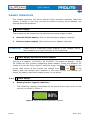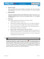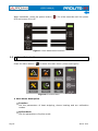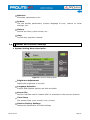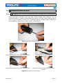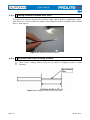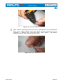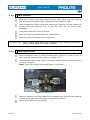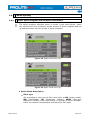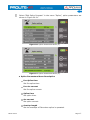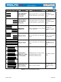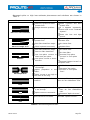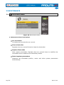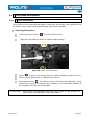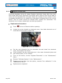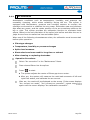
1
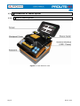
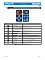
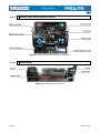
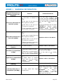
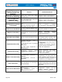
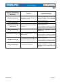
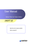
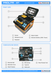
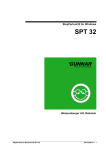
PROLITE-41
OPTICAL FIBRE FUSION SPLICER
Version
1.0
- 0 MI2006 -
Date
January 2014
Software Version
v2.20/v1.31/ROM: v0.30
SAFETY RULES
*
The safety could not be assured if the instructions for use are not closely
followed.
*
This product is designed for splicing glass optical FIBREs used for communication
and it is strictly forbidden to splice other substances. Mis-operations can cause
electric shock, fire or personal injury. Please carefully read and observe the
following rules for your own safety.
*
The external charger is Class I equipment. For safety reasons plug it to a supply
line with the corresponding ground terminal.
*
Use the mains adapter in Over-Voltage Category II installations and Pollution
Degree 1 environments. It is for INDOOR USE.
*
Use the power supply unit provided by this product mix . Do not use other power
adapter, battery or power line. Do not use this product under other voltages so as
not to cause fire or electric shock.
*
When using some of the following accessories use only the specified ones to
ensure safety:
Power adapter.
Mains cord.
Electrodes.
*
Don't let liquid such as water or metal material drop into the equipment, otherwise
it may cause fire, electric shock or equipment breakdown. Stop using the
equipment, unplug the battery socket and contact PROMAX (00 34 93 184 77 00).
*
Must not use the fusion splicer under combustible or explosive environment ,
otherwise it may cause fire or explosion.
*
Observe all specified ratings both of supply and measurement.
*
Remember that voltages higher than 70 V DC or 33 V AC rms are dangerous.
*
Use this instrument under the specified environmental conditions.
*
The user is not authorised to manipulate inside the instrument:
Replacing electrodes.
*
Do not touch the electrodes when the fusion splicer is operating which may cause
injury by high voltage generated by arc of electrodes. Ensure that the power is off
and the power line has been unpluged when replacing the electrodes.
*
In the Maintenance section provides instructions specific to this intervention.
March 2014
*
Optical fibre fusion splicer must be repaired and debugged by professional.
Incorrect repair may cause fire or electrical shock. If a failure occurs, please
contact PROMAX (00 34 93 184 77 00).
*
Once smoking, bad smell or abnormal noise occurs, stop using the fusion splicer
immediately, unplug the power plug and contact PROMAX (00 34 93 184 77 00).
Continue using may cause fire, electric shock or equipment breakdown.
*
Disassembling or reassembling the fusion splicer, reassembling the battery or
power adapter is prohibited to avoid over-heating, burst or fire.
*
Please strictly follow the operation manual on how to use the battery. Wrong
operations can cause battery over-heating, burst or explosion leading to fire or
personal injury.
Please don’t use other methods beyond this manual to charge the battery.
Please don’t throw the battery into fire.
Please don’t connect positive and negative electrodes with reverse
interfaces.
Please don’t charge or discharge under high temperature, fire or directly
sunlight..
Please don’t throw or strike battery.
If the battery electrolyte leaks out, handle it carefully. If the spill contacts
skin or eyes inadvertently, you must thoroughly clean and immediately
take medical treatment, at the same time inform PROMAX (00 34 93 184
77 00).
*
Follow the cleaning instructions described in the Maintenance paragraph.
* Symbols related with safety:
March 2013
Specific Precautions
*
Don’t use or store Optical fibre fusion splicer in high temperature and under highly
humid environment otherwise it may cause damage to the equipment.
*
Don’t touch the heat shrinkable sleeve in the process of heating or just after
heating, for the high temperature may cause ambustion.
*
Don’t touch the equipment with wet hand, AC power line or AC plug, otherwise it
may cause electric shock.
*
Don’t use any other chemical except alcohol to clean the microscope lens, Vgroove or monitor, it may lead to blurred images or stains, even cause corrosion
and damage of equipment.
*
Please take appropriate dustproof measures when the equipment is operated
under dusty environment so as to avoid dust from entering the interior of the
equipment and cause breakdown.
*
Avoid the equipment from strong vibration and impact, it may cause equipment
damage. Please transport or store the equipment in specified carrying case.
*
When you activate the light-producing arc and the electrode under a voltage. Do
not open the lid and touch the electrode as it might damage.
*
The fusion splicer can only quartz glass fibre.
*
In case of any malfunction, breakdown or team entry into any type of material and
equipment immediately disconnect the external power supply and call service.
*
Do not use in presence of flammable substances.
*
Avoid dusty conditions and temperature or humidity.
*
When changing from cold to hot wait until thoroughly dry the condensation.
*
Do not disassemble the power module.
*
Maintenance are recommended once a year.
Descriptive Examples of Over-Voltage Categories
Cat I
Low voltage installations isolated from the mains.
Cat II Portable domestic installations.
Cat III Fixed domestic installations.
Cat IV Industrial installations.
March 2014
March 2013
TABLE OF CONTENTS
1 INTRODUCTION ........................................................................................... 1
1.1 Description ....................................................................................... 1
1.2 Introduce of Fusion Splicer.................................................................. 2
1.2.1 Host of Fusion Splicer ..................................................................... 2
1.2.2 Keyboard...................................................................................... 3
1.2.3 Optical Fibre Fusion Splicer Device ................................................... 4
1.2.4 Tube Heater .................................................................................. 4
1.2.5 External Interface .......................................................................... 5
1.3 Package Content ............................................................................... 5
2 BASIC OPERATION ....................................................................................... 6
2.1 Power Supply .................................................................................... 6
2.1.1 Power Supply by External Power Adapter .......................................... 6
2.1.2 Power Supply ................................................................................ 6
2.2 Startup and Shutdown ....................................................................... 7
2.3 Menu Introduction ............................................................................. 8
2.4 System and Function Settings ............................................................. 9
2.5 Preparations Before Splice .................................................................11
2.5.1 Stripping Fibre’s Other Protective Layers Outside the Coating Layer .....11
2.5.2 Placing Protection Sleeve Over Fibre ................................................12
2.5.3 Strip and Clean Outer Coating of Fibre .............................................12
2.5.4 Fibre Cleaving ..............................................................................14
2.5.5 Place Optical Fibre ........................................................................14
2.6 Fusion Splicing .................................................................................15
2.6.1 Select Splice Program and Set Splice Parameters ..............................15
2.6.2 Automatic Alignment and Head-face Inspection .................................18
2.6.3 Arc Splice ....................................................................................20
2.6.4 Splice Loss Estimation and Quality Assessment .................................20
2.7 Tension Test ....................................................................................22
2.8 Splice Results Storage and Query .......................................................22
2.9 Heating Protection Sleeve ..................................................................23
3 MAINTENANCE ...........................................................................................26
3.1 Maintenance Menu ............................................................................26
3.2 Electrodes Maintenance .....................................................................27
3.2.1 Clean Electrodes ...........................................................................27
3.2.2 Remplace Electrodes .....................................................................28
3.2.3 Arc Calibration..............................................................................29
3.3 Cleaning of Fibre Fusion Splicer ..........................................................30
3.3.1 Clean the V-groove .......................................................................30
3.3.2 Clean the Microscope.....................................................................31
3.3.3 Clean the Fibre Presser Foot ...........................................................32
3.3.4 Clean the Heater...........................................................................32
4 SPECIFICATIONS ........................................................................................33
ANNEX 1
WARNING INFORMATION ...............................................................35
ANNEX 2
PROBLEMS AND TROUBLESHOOTING...............................................38
March 2014
March 2013
OPTICAL FIBRE FUSION SPLICER
PROLITE-41
1 INTRODUCTION
1.1
Description
PROLITE-41 optical fibre fusion splicer is a mini fibre splicing equipment which
is compactly designed, easy to carry and operation. It has vivid and exquisite
image-forming system and high precision image processing technology on fibre
alignment which leads to its high proficiency in splicing and low loss. Its beautiful
operation interface and body design which conforms to operation principle of
ergonomics greatly improve user experience. It is equipped with large capacity
lithium battery which provides reliable guarantee for a long time fieldwork. In
summary, PROLITE-41 is a totally automatic small, light and beautiful Optical
fibre fusion splicer with high performance, high safety, low power consumption
and can be easily operated.
March 2014
Page 1
1.2
1.2.1
Introduction of Fusion Splicer
Host of Fusion Splicer
Figure 1. Host Machine View
Page 2
March 2014
1.2.2
Keyboard
Figure 2. Keyboard View
Keyboard Icon
Name
Power key
Function
Power on/off.
Sleeve heating Key Start sleeve heating.
Exit
Key/switch
Return to previous menu field X, Y switch
key of XY field of
in Optical fibre mode.
view
Enter menu. Press an enter key on the
Menu/Confirm
menu.
Reset key
Equipment reset.
Start Key
Start alignment. Start fusion splicing.
Up key
Menu cursor moves upward.
Down key
Menu cursor moves downward.
Left key
Right key
Menu cursor moves to the left reset. It
edits the current option.
Menu cursor moves to the right. It edits
the current option.
Table 1. Keyboard Function Descriptions.
March 2014
Page 3
1.2.3
Optical Fibre Fusion Splicer Device
Figure 3. Optical Fibre Fusion Splicer Structure.
1.2.4
Tube Heater
Figure 4. Tube Heater Structure.
Page 4
March 2014
External Interface
1.2.5
Figure 5. External Interface.
1.3
Package Content
Check that your package contains the following elements:
PROLITE-41 Optical Fibre Fusión Splicer.
External DC charger.
Mains cord for external DC charger.
Cleaver.
Backup Electrode Bar.
Cooling Tray.
Pincers.
Transport Suitcase.
Stripper.
Drop cable Stripper.
Tube heater magnetized clamp backup.
Several pairs of magnetized Clamps (Jigs).
Dust blowing ball and brush.
Alcohol dispenser.
Box with Sleeves.
USB cable to connect to PC.
Quick Start Guide.
NOTE: Keep the original packaging, since it is specially designed to protect the
equipment. You may need it in the future to send the analyser to be
calibrated.
March 2014
Page 5
2 BASIC OPERATION
This chapter describes the fusion splicer’s basic operation methods. Read this
chapter in detail. It can help you use the splicer correctly, avoid damage and
causing abnormal problems.
2.1
Power Supply
This product can be charged by the following two power supply modes:
►
Internal lithium battery (with no external power adapter inserted).
►
External power adapter (with external power adapter inserted).
ATTENTION:
2.1.1
Please use the supporting power adapter of this product. Using
other adapters can cause anomaly of the equipment.
Power Supply by External Power Adapter
The input of adapter: 100-240V,1.4A ,50/60HZ. The output of adapter: 13.5V,
5A. Please use this product’s supporting power adapter. Insert the adapter’s DC
output line into the fusion splicer’s external power interface. The Indicating icon
” into “
”. If the
at top right corner of the monitor will change from “
battery pack has already been installed in the fusion splicer, the adapter will
charge the battery pack while supply power for the splicer.
2.1.2
►
Power Supply
Battery electric capacity indication
The remaining capacity percentage will be shown at top right corner of the
monitor, as shown in Figure 1.
Figure 6. Show the Remaining Battery Capacity.
Page 6
March 2014
Battery Charge
►
When connected with exterior adapter, the battery pack will be charged.
The charging time varies with the remaining capacity. The longest charging
time is 3 hours.
Battery alarm
►
When the remaining capacity of the battery pack is lower than 10% or it is
unable to guarantee the normal work of the fusion splicer, it will show alarm
information on the monitor. Users shall immediate charge it or use adapter
to supply power.
Warnings
►
When using the battery pack, follow the instructions below.
Please charge fully for the first use.
Please check the battery capacity before use. If the battery capacity is
low or it has shown under-voltage alarm, please charge immediately.
Please do not charge or store battery pack under high temperature or
direct sunlight in order to avoid aging.
Please charge the battery fully for long time storage.
Battery pack is easily depleted. Repeated charge and discharge will
make the charging ability of it decreased. When the battery is full of
electricity but can only be used for short time, it is time to replace with
designated type of battery timely.
2.2
Startup and Shutdown
To start the equipment, press the power button “
”. The power LED on the
operation panel will turn red and the buzzer will buzz. The monitor showcases the
fibre observation interface after all motors are reset to their initial positions, as
shown in Figure 2. Then the power supply mode will be automatically recognized.
If you use battery pack for power supply, the interface will showcase its
remaining power. The monitor will indicate abnormality information if it finds out
that the system is abnormal when start the equipment.
March 2014
Page 7
When shutdown, press the power button “
LED and screen turn off.
” for a few seconds until the power
Figure 7. Fibre Observation Interface
2.3
Menu Introduction
Press the Menu button “
” to enter the main menu (view next figure).
Figure 8. Function Menu
► Main Menu description
Function
Set the parameters of heat stripping, sleeve heating and arc calibration
modes.
Splice Mode
Set the parameters of splice mode.
Page 8
March 2014
Maintain
Electrode maintenance, etc…
System
Set the display parameters, system language & time, restore to initial
settings, etc…
History
Record arc times, splice results, etc…
Help
Provide key operation manual.
2.4
System and Function Settings
► System Setting Menu description.
Figure 9. System Setting Menu.
Brightness Adjustment
Adjust the brightness of monitor.
Language Selection
English and Spanish caption are both provided.
Screen flip
Monitor interface can be rotated 180° to showcase in the reverse direction.
Time Setup
Set system time, year, month, hour, minute.
Restore Factory Settings
Restore all parameters to initial settings.
March 2014
Page 9
Power saving mode
Set automatic dormancy or shutdown.
Silent Mode
Turn up or down the buzzer.
► Function settings menu description
Figure 10. Function Settings Menu.
Sleeve heating mode
Set the sleeve heating time, typical heating time 35 seconds (60mm),
28 seconds (40mm).
Arc compensation
If this factor is set "on", the latter current will be used to fusion splice.
Tension Test
If this is set "on", after splice is completed, the equipment will restore and
tension test will perform itself.
Reset Waiting Time
If the Tension test is set “off” , the system will restore the equipment after
the waiting time is over.
Auto Starting
If the Cover is set “on”, it will perform slice itself when the cover is lidded.
Page 10
March 2014
2.5
Preparations Before Splice
2.5.1
Stripping Fibre’s Other Protective Layers Outside the Coating Layer
Clean the fibre (100mm from the tail) cotton dipped with alcohol. If it is
butterflied fibre, it needs a butterflied fibre pincers to strip outer coating 40mm
from its tip, as shown in Figure 11. Protective Layers of Other kinds of fibre can
be stripped by miller pincers and scissors (view Figure).
Figure 11. Butterflied Fibre Strip.
Strip external plastic layer with miller pincers.
Cut off the wool with scissors.
Strip Internal plastic layer with miller pincers.
Strip the only one plastic layer with miller
pincers.
Figure 12. Single Core Fibre Strip.
March 2014
Page 11
2.5.2
Placing Protection Sleeve Over Fibre
The sleeve is used to protect the junction after splice. Before installation, make
sure there is no dirt inside the sleeve and keep the sleeve straight with optical
fibre, (view figure).
Figure 13. Placing Protection Sleeve.
2.5.3
Strip and Clean Outer Coating of Fibre
Strip outer coating 30mm from its tip with a stripping pincers (view
figures).
Figure 14. Stripping Length of Coating Layer.
Page 12
March 2014
Figure 15. Manual Stripping.
After manual stripping, clean scrap of the coating layer by circulating the
fibre using cotton dipped with high purity alcohol starting from the
interface of coating layer and bare fibre (view figure). The alcohol
dispenser can be also used to clean the fibre.
Figure 16. Clean Fibre.
March 2014
Page 13
2.5.4
Fibre Cleaving
Open the Cleaver cover and place the fibre with clamp into the cleaving
slot and keep the optical fibre vertical with the cleaver surface.
Press forward the fibre clamp and ensure the forefront of the clamp lies
closely with the cleaving slot. If not, the fibre can be longer than
expected.
Press down the fibre cover to cleave.
Open the cover and take away the cleaved fibre.
Take out the scrap and put into scrap box.
ATTENTION:
2.5.5
When cutting head face is not qualified or the cleaving cannot be
down, please adjust the blade of cleaver.
Place Optical Fibre
Open windproof cover to check whether the v-groove is clean or not. If
not, cleaning shall be down. Refer to chapter 3.4.1.
Place cleaved fibre (with clamp) into both-sided clamp slot and ensure it
is in the v-groove.
Note: The 0.9R clamp goes upside down (see figure).
Figure 17. Fibre-Place.
Observe whether the fibre head face is between the electrode tip and the
v-groove and near the electrodes; if not, Remake fibre.
Press the windproof cover lightly.
Page 14
March 2014
2.6
Fusion Splicing
2.6.1
Select Splice Program and Set Splice Parameters
The splice program selection menu is shown in the next figures. Users
can choose from the 40 factory preset groups of splice program and set
up and store their own 80 groups of splice program.
Figure 18. Splice mode menu (a).
Figure 19. Splice mode menu (b).
► Splice Menu Description
Fibre type
Set according to the type of fibre used such as SM (single mode),
MM (Multimode), DS (Dispersion shifted), NZDS (Non-zero
dispersion shifted). Each fibre preset 10 groups of splice program.
Users can choose corresponding one based on fibre type.
March 2014
Page 15
Splice operate mode
Automatic or Manual.
Splice program No.
40 groups preset splice program, 80 groups of users-set splice
program.
Edit splice program
Edit splice parameters under the current number of program, as
shown in figure 19.
Clean Arc time
Cleaning Arc means cleaning exquisite dust on the fibre surface by
short-time arc. The duration ranges from 0 to 1 second.
Surface angle threshold
An error message is displayed if the head face angle of either left or
right side of fibre exceeds the limit. The setting range is 0-5°.
Fibre angle threshold
An error message is displayed if the clamp angle of the two fibres
spliced exceeds the angel Limit. The setting range is 0-4°.
Align offset threshold
An error message is displayed if the misalignment of the two fibres
spliced exceeds the misalignment limit. The setting range is 0.0-1.5
μm.
Loss threshold
An error message is displayed if the estimated splice loss exceeds
the loss limit. The setting range is 0 - 0.2 db.
Compensation arc time
Splice loss may be improved by compensative arc in some cases.
Fibre Alignment Mode
Cladding align or core align can be set.
Fast splice mode
It can be set "on" or "off" which can accelerate alignment.
Page 16
March 2014
Select “Edit Splice Program” in the menu “Splice”, splice parameters are
shown in Figure 20-21.
Figure 20. Splice Parameters Menu (a).
Figure 21. Splice Parameters Menu (b).
► Splice Parameters Menu Description
Pre-Splice time
Set Pre-splice time.
Pre-Arc current
Set Pre-splice current.
Splice time
Set splice time.
Arc current
Set splice current.
Overlap length
Set the overlaps of fibre when splice is operated.
March 2014
Page 17
Splice Propulsion Speed
Set propulsion speed when fibres are spliced.
The Second Arc
Close or open the second arc.
The Second Arc Time
Set the second arc time.
The Second Arc Current
Set the second arc current.
2.6.2
Automatic Alignment and Head-face Inspection
This product uses an image processing system to observe the optical fibre in
order to ensure good splicing. However, in some cases, the image processing
system may not find out splice error. Therefore, it needs conducting visual
inspection of the fibre through monitor to obtain good splice results.
”, the fibre enters automatic alignment process and the
Click the Start button “
left and right optical fibre start to do opposite movement. After cleaning arc, the
system will automatically check the fibre head face. If the fibre head face is too
bad to splice, the monitor displays an error message. If the fibre head face is
good, alignment continues. After fibre alignment, the monitor shows angles of
the left and right head face. An error message is displayed if the cleave angle of
either left or right fibre ends exceeds the angle limit. Then users need to recleave optical fibre.
ATTENTION:
Cleave Limit and Misalignment limit could be set in the “Splice
Mode” menu.
When it shows images and messages as shown in Table 2 in the process of at
automatic alignment, the equipment will be reset automatically. Users can also
press reset button “
fibre.
Page 18
” to reset equipment and re-cleave or re-place optical
March 2014
Images (X/Y axis)
Message
Possible Reason
Measure
The right fibre
placement is
incorrect.
Replace or
Right optical fibre is not placed
re-cleave optical
in the V-groove, or too short.
fibre.
The left fibre
placement is
incorrect
Left optical fibre is not placed
in the V-groove, or too short.
Abnormal
alignment
Replace or
Left or right Fibre is not placed
re-cleave optical
in the V-groove.
fibre.
Replace fibre
left or right fibre is cleaved too Place or re-cleave
short.
optical fibre.
Replace fibre
Replace or
left or right fibre is cleaved too
re-cleave optical
long.
fibre.
Optical fibre
head face angle
is not proper
Problems occur in the process
of cutting (spurs, burrs,
beveled, concave core).
Re-cleave optical
fibre.
Optical fibre is
not available
Dust on fibre surface.
Re-clean and
replace optical
fibre.
Replace or
re-cleave optical
fibre.
Table 2. Abnormal Alignment Note.
March 2014
Page 19
2.6.3
Arc Splice
After fibre alignment, the monitor will display the message "alignment is OK”. At
this time you can press the start key “
” to splice fibre, or press the reset
button to reset equipment. If it is set to automatically splice, no press is needed.
2.6.4
Splice Loss Estimation and Quality Assessment
When fibre splice is completed, the loss estimated amount will be displayed on
the right side of the monitor. If fibre splice is abnormal, such as: too thick, too
thin, separated, bubbles-containing, with thin line, etc. An error message will be
displayed on the monitor and users need to re-splice or re-arc. If there is no
error, but the splice effect observed through the monitor is not good, it is
recommended that users re-splice. Note that sometimes the splice point looks
thicker than the rest, but it is normal which does not affect splice loss.
If effect of fibre splice is normal, but fibre splice loss exceeds the limit amount,
an error message will be displayed on the monitor. The limit amount of loss can
be set in “Splice Mode”.
In some cases, compensative arc may improve splice loss. When splice is
” to re-arc. After re-arc, the system will
completed, press the start key “
re-detect optical fibre to estimate splice loss and determine whether it is
reasonable.
Page 20
March 2014
Abnormal splice or high loss estimate phenomena and solutions are shown in
Table 3.
Phenomena
Reason
Solutions
Dust on V-groove or fibre
presser foot.
Clean V-groove and fibre
presser foot.
Image detection problem.
If it appears repeatedly,
users need to do “Calibrate
System”.
Fibre core axis mismatch
Fibre core angle error
Bubbles
Clean the lens and light
source.
Dust on V-groove or fibre
presser foot.
Clean V-groove and fibre
presser foot.
Poor fibre head face angle.
Re-cleave fibre.
Fibre is placed incorrectly.
Replace fibre.
Poor fibre head face angle.
Re-cleave fibre.
Dust on Fibre head face.
Re-clean fibre.
Low Pre-splice current or
short-time pre-splice.
Increase “Pre-splice
Current” or “Pre-splice
Time”.
Low splice current or shorttime arc.
Increase “Splice Current” or
“Splice Time”.
Do “Calibrate System”.
Splice propulsion force is
not enough.
Fibre Separation
Splice
slow.
propulsion
is
Decrease “Pre-splice
Current” or “Pre-splice
Time”.
too
Spice current is too high or
arc time is too long.
The splice propulsion force is Decrease “Overlap Length”,
excessive.
then do “Arc Calibration” test.
Thick
The splice propulsion force
is not enough.
Increase “Overlap Length”,
then do “Arc Calibration”
test.
Splice current is excessive.
Decrease “Splice Current”.
Thin
Splice current is too small.
Increase “Splice Current”.
Line
Table 3. Abnormal Alignment Note.
March 2014
Page 21
2.7
Tension Test
If “Tension test” is set "on", after splicing, tension test will automatically be
performed and the pulling force is 2N after splice. Menu operation is shown in
next Figure.
Figure 22. Tension Test.
2.8
Splice Results Storage and Query
Figure 23. History Records Menu.
► History Records Menu Descriptions
Total Arc number
Electrodes arc times since the last record is eliminated.
Reset Arc count
Eliminate arc times after electrodes are replaced.
Page 22
March 2014
Total records
The splice records having been stored by system.
View records
3000 groups of the latest splice records can be viewed. Users could query
the splice parameters and results.
Delete records
Delete all splice records.
Figure 24. Splice Records.
2.9
Heating Protection Sleeve
Select “Sleeve Heating Mode” in “Functions Setting” menu to enter
heating mode (view Figure).
Figure 25. Heating mode Menu.
March 2014
Page 23
► Heating Mode Menu Descriptions
Heating Program
User can choose the preset heating program based on different
protection sleeve or set the program himself.
Sleeve Diameter
1-8mm.
Sleeve Type
10-60mm ordinary sleeve, FC, SC.
Heating temperature
Heating temperature upper limit.
Heating time
Sleeve heating time.
ATTENTION:
It is better to use preset heating parameters.
Open the heater cover.
Open the Windproof cover, carefully remove the spliced fibre (without
clamp) and move protection sleeve to splice point while ensure splice
point is at the center of protection sleeve.
Place fibre with protection sleeve in sleeve heater, straighten the optic
fibre lightly and make sure protection sleeve‘s left end is aligned with and
heater slot’s left end , as shown in figure 26.Then close heater cover.
Figure 26. Place Fibre with Protection Sleeve.
Page 24
March 2014
Select “Sleeve Heating Mode” and the heating parameters.(if it is the same
with last time, you may skip this step).
Enter the heating key ”
” to start heating. The heat indication light is on.
Press heat shrinkage key ”
canceled.
” in the process of heating, the heating will be
When heating is completed, the heat indication light is off. Users need to
immediately turn on the heater cover and remove the optical fibre, as
shown in Figure 27.(Note: Do not use your hand to touch the heated
protection sleeve to prevent being burned.)
Figure 27. The Effect of Heating
Check the finished sleeve, if it is qualified, place the sleeve in the cooling
pans to let it cool down; if the finished sleeve has bubbles or dust inside, it
is suggested to repeat the operation.
March 2014
Page 25
3 MAINTENANCE
3.1
Maintenance Menu
Figure 28. Maintenance Menu.
► Maintenance Menu Descriptions
Arc correction
It checks and corrects the arc current.
Clean electrodes
Repeats short arc several times to clean the electrodes.
Replace Electrodes
After replace electrodes, Repeats short arc several times to stabilize the
electrodes and to measure the electrodes position.
Detect system parameters
Measures the electrodes position, motor and other system parameters
automatically
Page 26
March 2014
3.2
Electrodes Maintenance
Clean Electrodes
3.2.1
The surface of the electrodes will attach impurities during daily use and affect the
arc effect, hence users need to periodically clean the electrodes.
Cleaning Procedure:
Press the power button “
” to turn off the device.
Wipe the electrode tip with the cotton swab carefully.
Figure 29. Clean The Electrodes.
Press “
” to turn on the device and the power indication light will be on.
Select “Clean Electrodes” in “Maintenance Menu”.
”, the device will arc five times automatically, using
Press startup key “
powerful arc current to vaporize the impurity on the electrodes surface to
arc steadily and clean the electrodes.
ATTENTION:
March 2014
Don’t touch the electrode tips with hard object in the process of
cleaning to avoid damage to the electrodes.
Page 27
3.2.2
Remplace Electrodes
Electrodes depletes during its usage. Replace electrodes timely after they have
been arced 2000 times otherwise it will affect splice result of fibre which leads to
more loss and decrease fibre strength. When the number of arcs reaches 2,000,
a message reminding you to replace the electrodes is displayed when turn on the
device. The arc times should be cleared after replace the electrodes. The
electrode’s tip is sharp, please take care during operation.
Replacement Procedure:
Press “
” to turn off device before replacing.
Loosen the screw located on electrode cover, then take electrode out of
electrode slot as shown in figure 30.
Figure 30. Electrodes-replace.
Put the new electrode into the electrode slot and install the electrode
cover, then tighten the screw.
Check whether the two electrodes are in the same horizontal plane and
the vertical plane, if not reinstall.
Turn on the device, choose “Replace Electrodes” in the “Maintenance”
Menu.
Execute “Calibrate System” in the “Maintenance”.
Prepare and put fibre into the splicer, execute “Arc calibration” in the
“Maintenance” Menu.
Replacement completed.
Page 28
March 2014
Arc Calibration
3.2.3
Atmospheric conditions such as temperature, humidity, and pressure are
constantly changing, which arises variability during the arc. This splicer is
equipped with temperature, pressure and humidity sensors to monitor the
operation environment to stabilize the arc power. Electrodes wear and dirtiness
also affect arc power, and the center position of the arc sometimes shifts to the
left or right. This splicer provides Arc calibration function to eliminate these
effects. Based on the axis deviation of the splice joint before and after the arc to
judge the arc force to realize low loss and stable splice.
When one of the following circumstances exists, Arc calibration must be executed
before splice operation.
► Fibre type changes
► Temperature, humidity or pressure changes
► Splice loss increases
► Electrodes have been used for long time or stained
► After cleaning or replacing electrodes
Operation Procedure:
Select “Arc correction” in the “Maintenance” Menu.
Place cleaved fibres into the splicer.
Press “
” to start.
► The system adjusts the center of fibres gap to arc center.
► After arc, the system will measure the melt-back amounts of left and
right fibre axises, and calibrate the arc current.
After arc, the result will be displayed on the screen. If the screen displays
“Arc current too weak”, “Arc current too powerful”, repeat step
again until the screen displays “Arc calibration successful”.
March 2014
Page 29
If the screen displays “Arc calibration failed”, repeat step
.
After Arc calibration and splice position calibration complete, press “
to exit Arc calibration mode.
”
ATTENTION:
► Arc compensation often needs to be operated a couple of times, user should
follow the steps patiently.
3.3
Cleaning of Fibre Fusion Splicer
3.3.1
Clean the V-groove
The presence of impurities in V-groove will make the fibre image deviate from
the normal position, resulting in dis-alignment, causing more splice loss. So
users should regularly check and clean V-groove, the specific process is as
follows:
Open the windproof cover of Fibre fusion splicer.
Use the specific brush to clean the impurities in V groove bottom as
shown in vew Figure.
Please use the fine cotton swab dipped in alcohol to clean the bottom of
the V-groove. as shown in Figure 31 (b).
a
b
Figure 31. Clean the V-groove.
Page 30
March 2014
ATTENTION:
3.3.2
Do not touch the electrode tip. When cleaning, do not overexert or
using hard object (such as blades) to clean the V-groove in order
to avoid damaging the V-groove, which can cause breakdown.
Clean the Microscope
Fibre Fusion Splicer use image processing system to observe the optical fibre. If
the microscope lens get dirty, it will affect observations, leading to poor fusion
splicer results. So the microscope lens should be cleaned regularly, to maintain
the cleanliness of the lens. The specific process is as follows:
Turn off the splicer power, and open windproof cover.
Use cotton swab dipped in alcohol to gently wipe the lens, as shown in
Figure 32.
Then wipe the residual alcohol with clean, dry cotton swab, after that,
check the microscope lens whether it is tidy.
Turn on the power to observe whether there is dust on the image, if
there is, re-clean the lens.
Figure 32. Clean the Microscope.
ATTENTION:
March 2014
When cleaning, don't touch the electrodes, don't use hard objects
to touch the lens.
Page 31
3.3.3
Clean the Fibre Presser Foot
Dirt on optical fibre presser foot may cause fibre clamp problem and affect splice
results. The presser foot should be checked and cleaned regularly. The steps are
as follows:
Open windproof cover.
Use cotton swab dipped in alcohol to wipe the surface of the presser foot
as shown in Figure 33. Then use dry cotton swab to dry the presser foot.
Figure 33. Clean the Fibre Presser Foot.
3.3.4
Clean the Heater
The heater is easy to deposit dust and dirt, please clean the heating plate with a
dry cotton swab regularly as shown in Figure 34.
Figure 34. Clean the Heating Plate.
Page 32
March 2014
4 SPECIFICATIONS
Aplicable Optical Fibre Types
Single mode, Multi mode, Dispersion shift, Non zero dispersion
shift.
Aplicable Optical Fibre Core
Number
Single core.
Aplicable Optical Fibre Diameter
Cladding diameter: 125 µm, Coating diameter: 250 µm-900 µm.
Fusion splice Model
Prestore: 40 groups, User define: 80 groups.
Average Fusion Splice Loss
0.03
0.02
0.06
0.06
Alignment
Both core alignment and c ladding alignment.
Echo Loss
Better than 60 dB.
Fusion splice Duration Time
7 sec (typical parameter).
Loss Estimation of Fusion Splice
Yes.
Tension Test
2 N.
Monitor
LCD Color the 4,3".
Optical Fibre Marnification Times
X/Y:115 times, X or Y:230 times.
Power Supply
11,1 V Lithium battery.
13,5 V/5 A power adapter.
12 V power source available on the car.
Battery
typically work 180 times (Fusion splicing/Heating), Single battery
charge 3 Hour can be recycled 500 times.
Splice Results Storage
5000 groups of the latest records.
Data Interface
USB 2.0.
dB
dB
dB
dB
(Optical
(Optical
(Optical
(Optical
Fibre
Fibre
Fibre
Fibre
SM).
MM).
DS).
NZDS).
TUBE HEATER
Aplicable Optical Fibre Cable
Diameter
250 μm - 900 μm, 2 ~ 3 mm.
Applicable Sleeve Length
60 mm/40 mm (FP-03).
Heating time
35 sec (60 mm) / 28 sec (40 mm).
Heating temperature
120 ~ 160 °C.
March 2014
Page 33
OPERATING ENVIRONMENTAL CONDITIONS
Altitude
Temperature range
Max. relative humidity
Up to 2000 m.
From 5 to 45 °C (Automatic disconnection by excess of
temperature).
80 % (up to 31°C), decreasing lineally up to 50 % at 40 °C.
MECHANICAL FEATURES
Dimensions
A. 140 mm x A. 160 mm x Pr. 150 mm.
Peso
1,6 kg (Exclude battery), 1,8 kg (Include battery).
INCLUDED ACCESSORIES
AF-006C
AF-002C
Cleaver.
Backup Electrode Bar.
Cooling Tray.
Stripper.
Drop cable Stripper.
Tube heater magnetized clamp backup.
External DC charger.
Mains cord for external DC charger.
Several pairs of magnetized Clamps (Jigs).
Transport Suitcase.
Pincers.
Dust blowing ball and brush.
Alcohol dispenser.
Box with Sleeves.
USB cable to connect to PC.
Quick Start Guide.
RECOMMENDATIONS ABOUT THE PACKING
It is recommended to keep all the packing material in order to return the equipment, if necessary, to the
Technical Service.
Page 34
March 2014
ANNEX 1
WARNING INFORMATION
Warning information
(English information is
contained within the
brackets)
Reason
Countermeasures
or
,
► In the case of
Left fibre is cleaved too
re-cleave left fibre and make sure
short.
the cleaved length is appropriatel
Incorrect placement of
left fibre (LFPC)
The part of left fibre put ► In the case of
into V-groove is broken.
fibre
, replace left
Left fibre is not put in to ► If the breakdown do not match
the center of V-groove.
/ / ,do “Detect system
parameters”, If the problem
Left propulsion equipment
remains, please contact the
is incorrectly connected.
aftersales service department.
Right fibre is cleaved too
short.
The part of Right fibre put
into
V-groove is broken.
Right fibre placement is
Solutions refer to the above
incorrect (RFPC)
Right fibre is not put into
the center of V-groove.
Right propulsion equipment
is incorrectly connected.
Left and Right fibre
placement are incorrect The same as above
(LRFPC)
Solution refer to the above
Left fibre surface is dusty.
Left fibre is unqualified
(LFNQ)
► In the case of
, use alcohol
to clean the left fibre.
Left fibre is cleaved poorly,
such as core defect, cladding ► In the case of
defect or fibre incompleteness. fibre.
, remake
Right fibre surface is dusty.
Right fibre is cleaved
Right fibre is unqualified
poorly,
such as core defect, Solution refer to the above
(RFNQ)
cladding,
defect,
fibre
incompleteness
Right fibre is unqualified
The same as above
(LRFNQ)
Left fibre head face is
unqualified (LFEANQ)
March 2014
Left fibre head
exceeds limit
Solution refer to the above
face
► Re-cleave left fibre. If cutting
quality is still poor after multiple
trial,
replace
the
blade
angle
(Attention:
in
“Menu”->
“Splicing Mode” -> “Surface
Angle Threshold”, head face
angle limit can be set).
Page 35
Warning information
(English information is
contained within the
brackets)
Reason
Countermeasures
Right fibre head face is
unqualified (LRFEANQ)
Right fibre head face angle
Solution refer to the above
exceeds limit.
Left and Right fibre
head face are
unqualified (FANQ)
Left and Right fibre head face
Solution refer to the above
angle exceeds limit.
Estimated loss amount
is too much
Power is too insufficient
Replace electrodes
Records exceed limit
Alignment abnormity
Splice loss exceeds limit.
Clean
v-groove,
repeater
The selected program do “Arc correction” then splice again
not match the fibre type.
Current remaining battery less
Use power adapter to charge
than 2%.
Electrodes arc records exceed
the limit
Replace
electrodes
(operate
“Replace
Electrodes”,
“Detect
system parameters”)
Use USB data cable to transmit
Splice records exceed the limit the original splice records, then
operate “Delete Arc Records”
Fibre head face is dusty or
head face is poor.
Re-cleave and clean fibre, then
try alignment.
Windproof cover is pressed
If problem still remains, operate
too tightly.
“Detect system parameters” or
LED lamp brightness is restart the equipment.
inappropriate
Timeout abnormity
Field of view abnormity
Restart alignment and
Alignment
during
splice
Restart the equipment
process takes longer time.
problem still remains.
Electrodes placement
incorrect.
Equipment structure
damaged.
fusion.
if the
Operate
“Detect
system
parameters”, if the error still
exists, reinstall electrode bars. If
is
the problem remains, contact the
aftersales service department.
is
Data abnormity
It does not affect the operation,
The equipment is running in continue alignment and splicing.
abnormal state
Restart the equipment if the error
still exists.
Light source abnormity
LED lamp brightness is Operate
“Detect
system
inappropriate.
parameters”
firstly.
If
the
Windproof
cover
is problem remains, contact the
inappropriately placed.
aftersales service department
Page 36
March 2014
Warning information
(English information is
contained within the
brackets)
Reason
Countermeasures
Detect abnormity
Check the placement of fibre and
Abnormity in the process of wire connection. If the problem
“Calibrate System”
remains, contact the aftersales
service department
Power abnormity
Battery is abnormally charged
Heating shrinkage
abnormity
Sleeve heater can not operate
normally.
Store abnormity
Data could not be saved.
Data communication
Communicate abnormity
loss and loss.
Insert power adapter.
Restart equipment.
If the problem remains, contact
the aftersales service department
Contact the
department.
exists
aftersales
service
Restart equipment.
If the problem remains, contact
the aftersales service department
Image abnormity
Restart equipment.
The camera may be broken or
If the problem remains, contact
connector interface is loose.
the aftersales service department
Sensor abnormity
This abnormity does not affect
normal operation. Contact the
aftersales service department for
solution
March 2014
Inner sensor is broken.
Page 37
ANNEX 2
PROBLEMS AND TROUBLESHOOTING
Abnormal phenomena
arc sounds abnormally
arc delay or system
could not arc
system crashes when
arc
Arc calibration failure
Optical fibre alignment
error
Reason
Electrodes
placed.
are
Countermeasures
incorrectly Reinstall electrode strictly.
Electrodes are incorrectly
placed.
The electrode
wrapped by monox.
Electrodes
placed.
are
Environment
greatly.
tip
is
Reinstall electrode strictly.
Clean electrode tip or replace
electrode.
incorrectly Reinstall electrodes strictly.
affects
If the system warns that arc
current is too big, decrease splice
current, then do “Arc correction”
arc and vice versa.
Microscope lens, LED lamp
or V–groove is dusty.
Equipment power system is
faulty.
If the problem remains, contact
the
aftersales
service
department.
Clean the microscope lens, LED
lamp and V–groove, if the
problem remains, contact the
aftersales service department.
Re-make optical fibre, splice
again.
Fibre spliced joint’s
quality is poor
The keyboard has no
response
The screen has no light
or blurry colors
Page 38
Fibre is dusty.
The fibre type or fusion
Choose the right type of fibre
splice program selected is and fusion splice program.
wrong.
Operate “Arc correction” to
Fusion splice environment
obtain the appropriate intensity
changes greatly.
Control
equipment
is of arc.
broken.
Operate
“Detect
system
parameters”.
System crashes.
Turn off the power and restart.
Turn off the power and restart.
System crashes.
Wire of LCD monitor looses If the problem remains, contact
the
aftersales
service
or is broken.
department.
March 2014
PROMAX ELECTRONICA, S. L.
Francesc Moragas, 71-75
08907 L’HOSPITALET DE LLOBREGAT (Barcelona)
SPAIN
Tel. : 93 184 77 00 * Tel. Intl. : (+34) 93 184 77 02
Fax : 93 338 11 26 * Fax Intl. : (+34) 93 338 11 26
http://www.promaxelectronics.com
e-mail: [email protected]