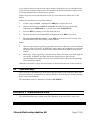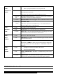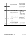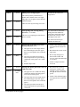
1
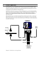
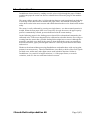
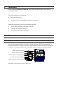
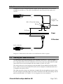
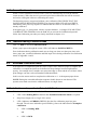
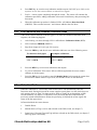
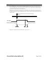
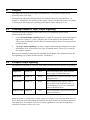
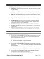
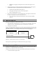
DoubleSense® Model III
User Manual
©SVENSKElektronikproduktion AB
DoubleSense Model III
Detailed User Manual
Revision date: 11 May 1999
Issued by: Pia Fridhill, HMS Sensors AB
EMC requirements
EN 5081-2
EN 5082-2
Valid for program version DS3-pv98
© Copyright Svensk Elektronikproduktion AB
Svensk Elektronikproduktion AB, Energigatan 8, S-434 37 Kungsbacka, Sweden
Phone: +46-(0)300-70 000 Fax: +46-(0)300-711 54
Email: [email protected] Web: www.doublesense.com
Table of contents
1
PRODUCT APPLICATION............................................................................................... 4
1.1
2
INSTALLATION................................................................................................................ 6
2.1
2.2
2.3
3
DOUBLE SHEET .................................................................................................................13
PAPER JAM .......................................................................................................................13
MISSED SHEET ..................................................................................................................14
LAYER ERROR ..................................................................................................................14
PAPER PRESENT................................................................................................................14
CALIBRATION ERRORS .....................................................................................................15
PASS TIME ERRORS ...........................................................................................................15
LIMITATIONS ....................................................................................................................16
OPERATING THE SENSOR ........................................................................................... 17
4.1
4.2
4.3
4.4
5
MECHANICAL CHARACTERISTICS .......................................................................................6
2.1.1 Cable connectors......................................................................................................6
2.1.2 Dimensions sender and receiver...............................................................................7
2.1.3 Mounting the Sender and Receiver ..........................................................................7
2.1.4 Dimensions processing unit .....................................................................................8
2.1.5 Mounting instructions processing unit .....................................................................8
ELECTRICAL CHARACTERISTICS .........................................................................................9
2.2.1 Power supply............................................................................................................9
2.2.2 I/O connector ...........................................................................................................9
2.2.3 Input and output connection.....................................................................................9
2.2.4 Additional sensor configuration .............................................................................10
POWER UP ........................................................................................................................11
2.3.1 Error indications at Power Up ................................................................................11
2.3.2 Sender and receiver alignment check .....................................................................11
DOUBLESENSE DETECTION FEATURES.................................................................... 13
3.1
3.2
3.3
3.4
3.5
3.6
3.7
3.8
4
SENSOR FUNCTION .............................................................................................................5
CALIBRATION MODE ........................................................................................................17
4.1.1 How to calibrate DoubleSense ...............................................................................17
4.1.2 Save calibration value ............................................................................................18
4.1.3 Indications during Calibration Mode......................................................................18
EXTENDED CALIBRATION MODE ......................................................................................18
4.2.1 Indications and operation in Extended Calibration.................................................18
4.2.2 Error indication after Extended Calibration Mode .................................................19
DETECTION MODE............................................................................................................19
4.3.1 Indication in Detection Mode.................................................................................20
NO DOUBLE MODE...........................................................................................................20
4.4.1 Indication in No Double Mode...............................................................................20
4.4.2 Switching to No Double Mode...............................................................................20
INPUTS ........................................................................................................................... 21
5.1
5.2
5.3
5.4
5.5
6
OUTPUTS........................................................................................................................ 26
6.1
6.2
6.3
6.4
7
TRIG INPUT ...................................................................................................................... 21
CALIBRATION INPUT ........................................................................................................ 22
RESET INPUT.................................................................................................................... 22
HALT INPUT ..................................................................................................................... 22
SIGNAL REQUIREMENTS................................................................................................... 23
5.5.1 Trig Input .............................................................................................................. 23
5.5.2 Calibration Input ................................................................................................... 24
5.5.3 Reset Input ............................................................................................................ 24
5.5.4 Halt Input .............................................................................................................. 25
CHOOSING GROUPED OR LOGIC OUTPUT SIGNALLING .................................................... 26
GROUPED OUTPUT SIGNALLING....................................................................................... 26
6.2.1 Stop Error output (O1) .......................................................................................... 27
6.2.2 Time Error Output (O2) ........................................................................................ 27
6.2.3 Layer Error output (O3) ........................................................................................ 28
6.2.4 Paper Present output (O4) ..................................................................................... 28
LOGIC OUTPUT SIGNALLING ............................................................................................ 29
SERIAL COMMUNICATION ................................................................................................ 30
SENSOR CONFIGURATION ......................................................................................... 31
DIP-SWITCH OVERVIEW............................................................................................................ 31
7.2 DIP-SWITCH CONFIGURATION SETTINGS.......................................................................... 31
7.2.1 Sampling length .................................................................................................... 32
7.2.2 Trig selection......................................................................................................... 32
7.2.3 External trig signal duration .................................................................................. 33
7.2.4 Error Output Duration ........................................................................................... 33
7.2.5 Selection of output signalling................................................................................ 33
7.2.6 Selection of communication .................................................................................. 34
7.2.7 Input and output configuration PNP/NPN ............................................................. 34
7.2.8 High Detection/Half duplex - Medium Detection/Full duplex............................. 34
8
OPERATOR PANEL ........................................................................................................ 34
PANEL OVERVIEW .................................................................................................................... 35
8.2 LED INDICATIONS ........................................................................................................... 35
8.2.1 Main indications.................................................................................................... 35
8.2.2 Sub error indications ............................................................................................. 36
8.2.3 Sub Error Operation .............................................................................................. 36
8.3 ERROR HISTORY SEARCH TOOL ....................................................................................... 36
8.4 OPERATION KEYS ............................................................................................................ 37
APPENDIX 1 - MAIN INDICATION MENU ................................................................................ 37
APPENDIX 2 - Sub Error Menu.................................................................................... 38
APPENDIX 3 - OPERATION KEYS ........................................................................................... 42
TECHNICAL SPECIFICATION ................................................................................................ 43
©Svensk Elektronikproduktion AB
Page 3(43)
1
Product application
The DoubleSense III is a double sheet sensor that can be used for detecting double sheets,
missed sheets, paper jam, and the presence of a paper passing the sensor. Further useable
functions are detection of pass time errors and the detection of one missing layer out of two
or major paper opacity differences in the paper flow.
DoubleSense can be used in any type of sheet feeding process, e.g. in enveloping machines
where it is extremely important that, for example, a confidential bank account draft does not
end up in the wrong envelope. DoubleSense also ensures a higher quality in collating
machines, foil wrapping machines and print feeders where the sensor checks the sheets at
each feeder station.
Other applications are, for example, the detection of a plastic card or sticker on a letter, the
detection of web splice pieces in a web offset system or recognition of a correct sheet fold.
These applications are to a certain extent customer specific and require software adjustments
for the due environment.
Processing unit
(Wallet size)
Power
supply
Receiver
Material
Sender
Serial cable
I/O cable
Control system
(PC/PLC/
relay/switch)
Diagram 1. DoubleSense system application.
1.1
Sensor function
DoubleSense detects sheets by sending invisible infrared light through the paper. Without
touching the paper the sensor can discover a double sheet on an early stage in the machine
process.
The sensor collects opacity data, i.e. light reduction data on a path stretching from lead edge
to trail edge of the sheet before it indicates the paper status. This method of scanning the
entire sheet results in the most accurate and reliable detection that can be found on the market
today.
The sensor is easily calibrated by pressing one single button – no other manual operation is
needed. When the next paper sheet is run completely through the sensor, the paper opacity
profile is automatically scanned, processed and stored in the sensor memory.
On the following papers in the feeding process data will be evaluated and compared to the
calibrated value. If the sensor happened to be calibrated on a double sheet the user will get a
warning from the sensor that a possible feeding failure might have occurred. Although the
material is too thick or too dark for the sensor to beam through the sensor can continue to
detect missed sheets, paper jam and signal whenever a sheet is present between the sender
and receiver.
Thanks to the advanced data processing DoubleSense can handle sheets with varying print
patterns in an accurate way. Therefor DoubleSense is not likely to deliver false error signals
on black areas, unlike many other light sensors used in double detection. Neither is
DoubleSense very sensitive to height variations, i.e. if the paper flutters, or to moist
variations, such as is the case with some inductive sensors.
©Svensk Elektronikproduktion AB
Page 5(43)
2
Installation
When installing DoubleSense Model III please follow the instructions in this chapter in
chronological order.
The sensor consists of the following:
•
Main processing unit.
•
Sender and receiver (including cable and cable connector).
Additional equipment can be ordered from HMS Sensors:
2.1
•
Power cable with battery eliminator connector.
•
I/O cable with modular connector.
•
Serial cable with modular connector.
Mechanical characteristics
2.1.1 Cable connectors
All cable connectors are polarised and cannot be placed in the wrong connector. The sender
has a 3-pole connector and the receiver has a 4-pole connector. The I/O (input/output)
modular connector have 8 poles whereas the serial modular connector has 4 poles. The power
connector is of battery eliminator type, often used as power connector in battery adaptors.
Sender (3-pole connector)
Receiver (4-pole connector)
Serial connector (4-pole modular)
I/O connector (8-pole modular)
Power connector (circular 1,9 mm)
Diagram 2. Connecting to the processing unit.
2.1.2 Dimensions sender and receiver
DoubleSense has one infrared transmitter (sender) and one photoelectric receiver that are
included in each delivery. The cable is shielded and 2 metres long for both sender and
receiver.
3-pole connector
Keep cable
straight ~5 cm
M8 - 0,75 mm fine thread
IR Sender
6
20
M8 nut
10-25 mm
13
Paper
0-5 mm
IR Receiver
4-pole connector
Diagram 3. Dimensions sender and receiver and location relative to paper.
2.1.3 Mounting the Sender and Receiver
For optimal beam through capacity the sender should be mounted 10 – 25 mm from the
receiver and the paper surface should pass 0-5 mm above the receiver. Direct the light beam
90° to the paper surface. In order to keep the receiver away from stray light and direct light
sources the receiver can be mounted above the sender as well as vice versa.
The sender and receiver lens housing is partly threaded ∅8 mm and delivered with an M8nut, a washer and an O-ring attached. The units can for example be clenched mounted on a
U-shaped or a key hole cut out.
The cable must not be bent to any side since it might effect the throughbeam capacity. Keep
the cable straight (no bending angle) for at least 5 centimetres from the lens housing. Do not
pull or twist the cables. See chapter 2.3.2 for alignment check at installation.
©Svensk Elektronikproduktion AB
Page 7(43)
2.1.4 Dimensions processing unit
The following diagram shows the mechanical dimensions of the processing unit.
26,0 mm
80,4 mm
94 mm
Front view
~40 mm
6,7 mm
62,5 mm
43,6 mm
Top view
86,8 mm
Diagram 4. Dimensional drawing processing unit.
2.1.5 Mounting instructions processing unit
The processing unit can be mounted on the outside of the machine to facilitate direct access
to the sensor operator panel, or inside an electrical cabinet as a unit integrated with the
machine control system. When placed out of reach for direct operation the sensor can be
controlled via inputs/outputs or serial communication.
•
The processing unit consists of sensitive electronic components. Please mount the unit
steadily in a vibration free environment.
•
All cable connectors have a security pull latch that prevent them from detaching during
use. Make sure that the connectors are properly fastened to ensure that the pull latch is
clenched into the connector.
•
Use M3-M4 screws (metric system) to fasten the processing unit. Use washers to avoid
that the plastic surface be damaged by the torque load.
2.2
Electrical characteristics
2.2.1 Power supply
The power connector is a battery eliminator type. Connect according to the following:
Connector
Symbol
Power (Up)
Max
Average
White (-)
Up
+12 (+/- 5%)
600 mA
125 mA
Min
80 mA
Black (+)
(Volt DC)
+24 (+/- 5%)
300 mA
70 mA
40 mA
2.2.2 I/O connector
The inputs and outputs are located in the modular connector (8-pin) named I/O connector.
The I/O cable connector has the following standard configuration:
Input 1 (Brown) - Trig
Input 2 (Blue) - Calibration
Input 3 (Yellow) - Reset
Input 4 (Green) - Halt
Output 1 (Red) - Stop Error
Output 2 (Black) - Time error
Output 3 (White) - Layer Error
Output 4 (Grey) - Paper present
Diagram 5. I/O modular cable connector configuration.
2.2.3 Input and output connection
The outputs can be configured as PNP or NPN. Please restrict voltage for inactive inputs and
outputs to between 0 V and Up in order not to damage the unit.
Config.
Outputs active
Max output current
PNP
Up - residual voltage (1 V)
150 mA at Up = 12 V
NPN
0 V + residual voltage (1 V)
250 mA
250 mA at Up = 24 V
The inputs are active at:
Config.
Inputs active
Inputs inactive
PNP
> 0,8 x Up
< 0,5 x Up
NPN
< 0,2 x Up
> 0,5 x Up
©Svensk Elektronikproduktion AB
Page 9(43)
PNP
DS3 INTERNAL
CONNECTIONS
RELAY
Transient-suppression
(diode 1N4148 or equal)
O UTPUT
DIODE
INPUT
SWITCH
INPUT
POWER SOURCE
-
-
+
+
DC UpV +/- 5 %
1
Diagram 6. Connection diagram PNP.
NPN
DS3 INTERNAL
CONNECTIONS
RELAY
Transient-suppression
(diode 1N4148 or equal)
O UT PUT
DIODE
INPUT
SWITCH
INPUT
POWER SOURCE
-
-
+
+
DC UpV +/- 5%
Diagram 7. Connection diagram NPN.
2.2.4 Additional sensor configuration
In order to adjust the sensor for specific machine
conditions, a number of sensor configurations are
available, e.g. NPN/PNP, signal duration etc.
Configurations can be made on the two DIP-switches
located on the circuit board inside the processing unit.
Access the DIP-switches through the plastic plug on the
processing unit. Set the switches carefully with the help
of a small screw driver, pencil or other sharp pointing
object. Find detailed description of the configurations in
chapter 7.
Access to DIP-switch
Diagram 8. DIP-switch access.
2.3
Power up
The sensor is automatically powered up when the power supply is turned ON. Precaution!
The power supply source must be turned OFF (0 VDC) before the power connector is
plugged into the processing unit in order to avoid damage.
At power up (power voltage turned on) the sensor automatically checks the alignment and
function of the sender and the receiver, the function of the CPU and other hardware
components.
The power up sequence:
1.
All LED:s first turn RED (1 sec) and then GREEN (1 sec).
2.
If the hardware is functional the Operation Mode LED will start indicating due mode
directly after the power up sequence.
If the sender and the receiver are misaligned, or if dust or other articles hinder a sufficient
amount of light to reach the receiver, the sensor will immediately show an error message, see
Power up error indication menu on the next page. When the error has been removed the
sensor will continue for 3 seconds to show the error message before it is turned off.
To manually turn the sensor ON/OFF: Press the keys CAL and ND simultaneously for 2
seconds. (The sensor will not perform the hardware check at manual ON/OFF).
Alternative: Activating Input 3 for more than 2 seconds will turn the sensor ON/OFF.
2.3.1 Error indications at Power Up
If the LED:s fail to go through the “RED - GREEN” sequence at power up and all LED:s are
OFF the unit may be damaged.
If any errors are found at the power up sequence they will immediately be indicated on LED
2 and LED 3 and on the outputs. The error indication table (diagram 9) on the next page
displays the possible error sources displayed with a combination of RED, GREEN, flashing
RED and flashing GREEN on the two LEDs. See diagram 9, page 12 for Power up sub
indication menu.
The sensor can be restarted by holding down CAL and ND simultaneously for more than 2
seconds.
2.3.2 Sender and receiver alignment check
At installation, check the alignment of the sender and the receiver:
1.
Hold down the CAL and RES key simultaneously.
2.
The LED:s will perform an alignment check to indicate optimal alignment:
•
If all LED:s are GREEN the alignment is 98-100% optimal.
•
If more than one (1) LED shows RED or OFF then there is dust or misalignment.
Note! All LED:s must show GREEN in order to reach optimal sensor performance. Please
align the sender and the receiver so that all LEDs show GREEN. Be careful not to bend the
sender and the receiver cables since a sharp bend might effect the alignment.
©Svensk Elektronikproduktion AB
Page 11(43)
Power up error indication menu
LED
Outputs
Error
Action
LED 2
Indication
YFlashing
red
O1 and O4
active.
Remove dust or article
hindering the infrared light.
LED 3
l Red
(1 0 0 1)
Dust or other articles
(paper) in between the
sender and the receiver.
LED 2
YFlashing
red
LED 3
l Green
LED 2
l Red
LED 3
l Green
LED 2
l Red
LED 3
YFlashing
red
LED 2
l Red
LED 3
YFlashing
green
Sender and receiver not
properly aligned.
Align sender and receiver.
The sensor continues to
check for another 3 sec
before indication is turned
off.
No
indication
DIP-switch settings
incorrect.
Check the DIP-switch
settings.
No
indication
Hardware error RAM
memory.
Sensor defect or damaged.
O1 and O3
active.
Hardware error DA
converter.
Sensor defect or damaged.
Hardware error
EEPROM.
Sensor defect or damaged.
(1 0 1 0)
No
indication
Diagram 9. Power up error indication table.
Contact Svensk Elektronikproduktion if the sensor indicates hardware error, +46-(0)300-70 000.
3
DoubleSense Detection Features
This chapter describes:
•
What information the user can get from DoubleSense III.
•
Definitions of what is meant by each information, e.g. a double sheet, a missed sheet or
a layer error.
•
Short description of how the sensor indicates the different situations and how they are
displayed.
(A detailed table overview of LED indications is found in chapter 8. Input and output
functions are found in chapter 5 and 6).
3.1
Double sheet
A double sheet is defined as the paper being twice as thick or twice as dark as the calibrated
sheet. A double sheet can consequently be more than 4 sheets if the sensor was calibrated on
2 sheets, more than 8 sheets if the sensor was calibrated on 4 sheets, etc.
When a double sheet passes the sensor the infrared receiver receives approximately half of
the light compared to the light it received during the calibration. The light reduction values
(opacity) are processed in an algorithm to evaluate whether the reduced light is caused by the
variations in the printed colours or by a “real” double sheet.
The indications for double sheets are:
3.2
1.
LED 2 indicates DOUBLE (RED).
2.
Stop Error Output or Logic I/O:s are active (see chapter 6 for details).
Paper Jam
Paper Jam is defined as the presence of a paper in the sensor when it is expected NOT to be
there. In this situation it is possible that paper is stuck (jammed) or overlapped by another
paper.
The sensor detects a Paper Jam when Trig Input is deactivated and a paper is still in between
the sender and the receiver. The following indications are made for paper jam:
1.
LED 2 indicates Paper Jam (GREEN).
2.
Stop Error Output or Logic I/O:s are active (see chapter 6 for details).
Note! The user must provide the sensor with an input signal in order for the sensor to know
during what time to expect a paper between the sender and receiver. To use this function a
selection must be made on the DIP-switch. See chapter 5 and chapter 7.
©Svensk Elektronikproduktion AB
Page 13(43)
3.3
Missed sheet
A missed sheet is defined as the absence of a sheet in the paper feeding process.
The Trig Input on the sensor must be activated to inform the sensor when a sheet is expected
to appear between the sender and the receiver. If no paper is found to be present when Trig
Input is activated the following indications will be given:
1.
LED 3 indicates MISS (RED).
2.
Stop Error output or Logic I/O is active (see Chapter 6 for details).
Note! The user must provide the sensor with an input signal in order for the sensor to know
when to expect a paper between the sender and receiver. To use this function a selection must
be made on the DIP-switch. See chapter 5 and chapter 7.
3.4
Layer error
A layer error is defined as one (1) missing layer out of two (2), i.e. if the sensor calibrated on
two layers of paper it will signal when only one layer passes the sensor. The missing layer is
considered by the sensor as an opacity value that is twice as high as the stored calibration
value, i.e. too light paper. Consequently, if the sensor is calibrated on four (4) layers of
paper, it will detect if two (2) layers are missing, provided that the opacity of each layer is
approximately the same.
This information can be used in three ways:
•
As a warning that the calibration was possibly carried out on a double sheet.
•
To warn if a paper set is missing one (1) layer out of two (2).
•
To warn if the paper opacity is too light (wrong paper) compared to the calibrated
opacity value.
The indications for a layer error are:
3.5
1.
First: LED 3 indicates ERROR (GREEN).
2.
Second: When ERR key is held down LED 2 is GREEN and LED 3 is GREEN, the
combination for missing layer/too light paper.
3.
Layer Error Output (O3) is active.
Paper Present
Paper Present is defined as the presence of a paper between the sender and the receiver. The
sensor detects the lead edge and signals until the trail edge.
The Paper Present detection can be used for:
•
Detecting the presence of a paper.
•
To count the number of paper sheets.
•
To detect the length of the paper in terms of paper passing time, i.e. the time between
positive and negative flank .
•
To detect missing sheets, i.e. IF NOT Paper Present THEN Missed sheet.
Paper Present is indicated by:
3.6
1.
LED 4 indicates PAPER (GREEN) for as long as the paper is present.
2.
The Paper Present output (O4) active from lead edge to trail edge.
Calibration Errors
The sensor detects three (4) different calibration errors:
•
Paper stand still. The paper was present for more than five (5) seconds between the
sender and the receiver during calibration.
•
Paper passing time too fast. The paper passing time was below the minimum of 23 ms
from lead edge to trail edge which is insufficient for a successful calibration.
•
Paper too dark or too thick. An insufficient amount of infrared light was received by
the receiver during calibration.
•
Extended calibration values needed. The paper print was complicated and the sensor
needs another 1 – 4 sheets in order to process the calibration values correctly.
•
Halt input activated during calibration. The sampling sequence was interrupted
during calibration. It is not permitted to stop the paper in between the sender and the
receiver during calibration.
The calibration errors are indicated by:
3.7
1.
LED 3 is GREEN for general ERROR. Error type is shown at sub error level. Press
ERR key to access sub error level. Go to APPENDIX 2 to read error type.
2.
Stop Error output (O1) or Logic I/O active.
Pass time errors
The sensor can warn the operator if the passing time is shorter or longer than the previous
pass time during detection. This can be used when checking for overlapping papers, damaged
papers or for confirming that the right paper enters the sensor.
•
If the paper pass time increases to more than 150% of the previous paper pass time.
•
If the paper pass time decreases to less than 67% of the previous paper pass time.
•
If the paper pass time during detection is less than 10% of the calibration pass time (10
times shorter).
•
If the paper pass time during detection is 10 times the calibration pass time (10 times
longer).
©Svensk Elektronikproduktion AB
Page 15(43)
•
If the paper has been present for more than five (5) seconds during detection .
The pass time errors are indicated by:
3.8
1.
LED 3 is GREEN for general ERROR. Error type is shown at sub error level. Press
ERR key to access sub error level. Go to APPENDIX 2 to read error type.
2.
Time Error output (O2) or Logic I/O active.
Limitations
The following factors influence the calibration and the detection of sheets:
1.
The printed colours reduce the infra red light that is sent through the paper. A black
printed paper reduces approximately seven times as much light as a white paper.
2.
The thickness of the paper. DoubleSense can handle white paper less than 20 g/m2 (e.g.
bible paper) up to one white carton 1000 g/m2.
3.
The level of transparency of the material. If a completely transparent sheet is put in
the sensor the infrared light will not be reduced, i.e. all of the light will go through the
material like sunlight through a window and detection is not possible. However, a
faintly coloured sheet, e.g. plastic material will reduce the light to some extent and
detection may be possible.
4.
The number of layers in the paper set, e.g. how many sheets the sensor has to consider
as being a single sheet. Folded sheets disperse the infra red light more than one, much
thicker carton does. Each layer disperses the light to a certain angle, and that angle is
consequently increased with each layer until the light is reduced to zero.
5.
The distance between folded sheets. If the sheets in a folded paper set are not tightly
pressed together the light is dispersed through each layer and reduced so much that the
receiver receives little or no light at all.
6.
The distance between the sender and the receiver. For optimal beam through
capacity the sender should be mounted aligned with the receiver at a distance from lens
to lens of 10-25 mm. The distance from the paper surface to the receiver should be 0-5
mm.
7.
Stray light directed towards the receiver may be mistaken for light from the infra red
sender since light bulbs or sunlight also contains frequencies of infra red light.
4
Operating the sensor
The sensor operates in four work modes: Calibration Mode, Extended Calibration Mode,
Detection Mode and No Double Mode.
The sensor is automatically turned ON at power up. If the sensor has been manually turned
OFF - then turn the sensor ON by pressing the keys CAL and ND on the operator panel for 2
seconds.
4.1
Calibration Mode
The Operation Mode LED indicates calibration mode when RED and the sensor is thereby
ready to calibrate on the next passing sheet.
In Calibration mode DoubleSense collects opacity data from the paper on a path reaching
from the lead edge to the trail edge of the paper (default). The collected opacity data is
processed and stored as an opacity profile to be used as a comparison value in detection
sheets.
If the sensor is configured to use the External Trig, the calibration begins at the Trig Input
positive flank and ends at the trail edge of the paper. If the sensor is configured for Interval
Detection (20 ms) the calibration starts at the paper edge or at the external trig, and ends after
20 ms. See chapter 7 – Sensor configuration.
4.1.1 How to calibrate DoubleSense
First make sure that no paper or other article is in between the sender and the receiver before
or at power-up.
If the sensor has pre-stored calibration values from previous runs, the LED 1 will indicate
Detection mode (GREEN) or No Double mode (flashing GREEN) when turned on.
Calibrate the sensor by going through the following steps or follow the quick guide:
1.
Press the CAL key on the sensor or activate the calibration input
(I2 < 2 sec). The Operation Mode LED turns RED to indicate
that the sensor is not yet calibrated and that the sensor is ready to
calibrate on the next passing sheet.
2.
Start the paper feeding sequence in your system and run one paper
completely through the sender and the receiver at normal machine
speed (0,5 – 4,5 m/s). The LED 4 indicates PAPER (GREEN) as
long as the paper passes through. Note! The sensor does not allow
paper stand-still during calibration!
3.
The Operation Mode LED turns GREEN to indicate that the
sensor is now in Detection Mode. The calibration has been
successfully achieved.
Press CAL
Feed paper
through
Calibration
finished
Note: If a paper is in between the sender and receiver when the calibration is activated, the
sensor will start calibration on the next following paper edge or Trig input.
©Svensk Elektronikproduktion AB
Page 17(43)
4.1.2 Save calibration value
When a correct calibration is achieved the values are automatically saved in the internal
sensor memory. When the sensor is powered up the latest calibration data will be restored
and can be used again without re-calibrating the sensor.
The detection process can proceed without a new calibration, PROVIDED THAT THE
SAME PAPER IS BEING PROCESSED! The Operation Mode LED will turn GREEN
immediately after power up sequence to indicate that the sensor is in detection mode, i.e.
already calibrated.
If the paper type, i.e. print pattern, colours or paper thickness, is changed YOU MUST RECALIBRATE THE SENSOR! Press the CAL key or activate the Calibration Input and
follow the Calibration procedure previously described in chapter 4.1.1.
4.1.3 Indications during Calibration Mode
LED 1 is RED to indicate Calibration Mode.
When a paper passes through the sensor LED 4 will indicate PAPER (GREEN).
Error indications during calibration mode are too long pass time, too short pass time, miss
sheet, paper jam, extended calibration and Halt input active during calibration. See Indication
menus in Appendix 1 and 2.
4.2
Extended Calibration Mode
If the paper has a complicated print the sensor requires more than one paper to complete the
calibration. A complicated print can be defined as sharp changes between high and low
opacity, for example when a smaller area at the lead edge is white and the rest is black. Other
print changes can also evoke an Extended Calibration Mode.
In this case the sensor needs to complete the calibration on 1 - 4 subsequent paper sheets.
NOTE! During the extended calibration sequence double sheets are not detected. The
operator must make sure that the calibrated sheets are single sheets.
4.2.1 Indications and operation in Extended Calibration
This situation is indicated and handled as follows:
1.
LED 1 turns flashing RED to indicate that Extended Calibration Mode is required.
2.
Stop Error Output (O1) or Logic I/O is active.
3.
LED 3 indicates an ERROR (GREEN) after the first calibration paper has gone
through. The sub error indication (press ERR key) shows the indication for incomplete
calibration:
•
LED 2 is flashing RED
and
•
LED 3 is RED
4.
Press RES key to reset the error indication and the outputs. DO NOT press CAL in this
sequence or else the sensor will have to start all over again!
5.
Feed 1 – 4 more papers completely through the sensor. The sensor will continue the
calibration procedure, adding calibration values until a satisfactory data processing has
been made.
6.
When the calibration procedure is finished LED 1 will indicate Detection Mode
(GREEN). This can take between 1 and 4 sheets added to the first sheet.
4.2.2 Error indication after Extended Calibration Mode
If the sensor cannot calibrate on the due paper even after the extended calibration mode
sequence, the following happens.
4.3
1.
After feeding 1-4 sheets through, LED 1 still indicates Calibration Mode (RED).
2.
LED 3 indicates ERROR (GREEN).
3.
Stop Error Output (O1) or Logic I/O is active.
4.
Press the ERR key and the sub error indication indicates one of the following errors:
Too thick/too dark paper
Incomplete calibration
LED 2 is RED
LED 2 is flashing RED
LED 3 is RED
LED 3 is RED
5.
Press the RES key to reset error indications and outputs.
6.
Try a new calibration. If the sensor fails to calibrate again then the sensor cannot
calibrate on the due paper.
7.
Press the ND key for 2 seconds to start No Double Mode. In this mode the sensor does
not check for double sheets or layer error, but all other errors are still detected.
Detection Mode
When the calibration is successfully achieved the sensor will automatically enter the
Detection mode. During this mode the sensor samples opacity data over the whole sheet on
each passing sheet (or from Trig input positive flank or during 20 ms depending on DIPswitch selections, see chapter 7). The data is first processed and then compared to the
previously stored calibration data. When the processing is finished the sensor signals the
status of the due paper sheet.
In Detection Mode the sensor detects:
1.
Double Sheets.
2.
Missed sheets (if Trig is active and selected on the DIP-switch, see chapter 7).
3.
Paper Jam (if External Trig and Trig held are selected on the DIP-switch, see chapter 7,
and Trig input is activated,).
©Svensk Elektronikproduktion AB
Page 19(43)
4.
The presence of a paper between the sender and the receiver (Paper Present).
5.
Correlation of the paper passing time.
6.
Missing layer/too light paper.
4.3.1 Indication in Detection Mode
LED 1is GREEN to indicate Detection Mode.
When a paper passes through the sensor LED 4 will indicate PAPER (GREEN).
4.4
No Double Mode
The paper is considered too dark or too thick in case an insufficient amount of infrared light
reaches the receiver during calibration. The sensor must now be switched over to No Double
Mode. In the No Double mode no doubles are detected, but the following situations will
continue to be detected:
1.
Missed sheets (if Trig is active and selected on the DIP-switch, see chapter 7).
2.
Paper Jam (if External Trig and Trig held are selected on the DIP-switch, see chapter 7,
and Trig input is activated,).
3.
The presence of a paper between the sender and the receiver (Paper Present).
4.
Correlation of the paper passing time.
4.4.1 Indication in No Double Mode
LED 1 is flashing GREEN to indicate No Double Mode.
If the sensor detected a too thick or too dark sheet during the calibration sequence or failed to
carry out calibration in extended mode, the following indication will inform the user about
the situation:
1.
LED 3 is GREEN to indicate that an error has occurred and the Stop Error Output (O1)
is activated.
2.
Access the sub indication menu by holding down the ERR key.
3.
The sub error indication indicates “Too thick/too dark paper” when:
•
LED 2 is RED
and
•
LED 3 is RED
Any other combination by LED 2 and LED 3 indicates another error. See APPENDIX
2 for a full description of sub indication errors.
4.4.2 Switching to No Double Mode
When the sub error indication has indicated “Too thick/too dark paper” the sensor can be
switched to No Double Mode.
5
1.
Manually switch the sensor to No Double Mode by pressing the ND key on the sensor
processing unit for more than 2 seconds.
2.
Alternative: Automatically set the sensor to No Double Mode by activating the
Calibration Input (I2) for more than 2 seconds.
Inputs
This chapter describes the four inputs on DoubleSense and the signal requirements for each
input. Note that all inputs and outputs do not necessarily have to be used. However, in some
applications the sensor requires certain signal inputs in order to perform functions selected on
the DIP-switches.
The inputs and outputs are located in the 8-pole modular connector (I/O connector), see
chapter 2 – Installation. The duration of the inputs and outputs can be set on the DIP-switch,
see chapter 7.
Name
Position
Trig
Input (1)
Wire colour Function
Brown
Calibration
Input (2)
Blue
Starts detection (sampling) when activated.
1. Sets sensor in Calibration mode when
activated (pulsed >15 ms).
2. Sets the sensor in No Double mode when
activated more than 2 sec.
Input (3)
Reset
Yellow
1. Resets latest error on positive flank.
2. Turns the sensor OFF when activated more
than 2 sec.
Input (4)
Halt
Green
Stops (halts) sampling during paper standstill. Used if paper stand-still is necessary.
Note: For all inputs 2 ms positive flank filter, 10 ms end flank filter.
Diagram 10. Table overview of sensor inputs.
5.1
Trig input
The trig input (I1 – Brown) is used when:
1.
2.
Detecting Paper Jam and Missing Sheets. The Trig Input should be activated by the
control system when a paper sheet is expected to be present between the sender and
receiver. DIP-switch 2 must be set to ON, see chapter 7.
•
If Trig is activated and no sheet is detected by the sensor within 4 ms then Miss
sheet error is indicated.
•
If Trig is deactivated and paper is found in between the sender and the receiver
within 4 ms the sensor indicates Paper Jam error. In order to use the Paper Jam
detection DIP-switch 2 and 3 must be set to ON, see chapter 7.
Starting the detection on a specific position on the paper. The sensor starts sampling
when Trig is activated (on positive flank) and ends when the paper trail edge is
detected.
©Svensk Elektronikproduktion AB
Page 21(43)
In order to use the Trig Input a selection must be made on DIP-switches 2 and 3, see chapter
7.
Application example: In a horizontal collator the paper is transported through the sender and
receiver by a metallic suction device. In this case the sensor would be unable to start
detecting the lead edge and sample over the metallic suction device. Instead the Trig input
starts the sampling directly after the suction device has passed the sender and receiver.
5.2
Calibration Input
The calibration input (I2 – Blue) is used for:
5.3
1.
Setting the sensor in Calibration mode. Achieve Calibration mode by activating the
Calibration Input for at least 15 ms. (The Calibration mode can also be set by using the
CAL key on the sensor operator panel).
2.
Setting the sensor in No Double mode (when the sensor does not detect double sheets).
Achieve No Double mode by activating the Calibration Input for more than 2 seconds
(>2 sec).
Reset Input
The Reset Input (I3 – Yellow) has two basic functions:
5.4
1.
To reset (deactivate) the error outputs. Pulse the Reset Input for 15 ms to reset active
error.
2.
To turn the sensor OFF or ON. Activate the Reset Input for more than 2 seconds.
Halt Input
The Halt input (I4 – Green) is used when the paper repeatedly is brought to a stand-still in
the machine. The Halt Input must be activated in order to interrupt the sensor detection
sequence. Paper stand-still is only allowed during paper detection if the Halt Input is
activated.
Note 1! In case the sensor does not receive information about paper stand-still it will not
perform a correct double detection.
Note 2! Paper stand-still is only allowed during detection and not during calibration.
If the paper has been in between the sender and receiver for more than five seconds the
sensor will indicate an error.
5.5
Signal requirements
The signal requirements for each input must be thoroughly followed by the installer. If the
signal requirements are not fulfilled the sensor will not be able to perform detection with
optimal function and reliability and perhaps, in some cases, not at all.
This chapter contains signal charts of each of the four inputs.
5.5.1 Trig Input
The Trig Input can be pulsed or held until after the paper trail edge, see chapter 7- Sensor
configurations, DIP-switch 3. The Trig Input can be activated anywhere on the paper. The
sensor must however receive a satisfactory amount of samples, at least 23 ms of paper
sampling is required before the trail edge.
1.
Trig held for miss sheet and paper jam detection:
Paper Jam
Sampling
Paper Jam
Detection
Trig Input
Diagram 11. Signal scheme for paper jam detection (DIP 2 – ON, DIP 3 – ON).
The Trig Input (I2) must be active until well after the paper has passed the sender and
receiver. If the Trig is deactivated when the paper is still present in the sensor, then a Paper
Jam error will be indicated.
2.
Trig pulsed for miss sheet detection (min 10 ms).
Paper 1
Paper 2 - Missed sheet!
Sampling
Paper 3
Sampling
Trig Input
Diagram 12. Signal scheme for miss sheet detection (DIP 2 – ON, DIP 3 – OFF).
The sensor starts sampling at the positive flank and continues until the trail edge of the paper.
©Svensk Elektronikproduktion AB
Page 23(43)
5.5.2 Calibration Input
Function
Signal time
Calibration
15 ms - 2 s
No Double Mode
>2s
•
Activate the Calibration Input at least 20 ms before the paper lead edge. If the
Calibration Input is activated when the paper is present between the sender and
the receiver, the sensor will calibrate on the next following sheet.
•
If the Trig Input is used for starting the detection sequence there must be at least
20 ms between the Calibration Input negative flank and the Trig Input positive
flank.
> 20 ms
Paper
Calibration Input
Diagram 13. Signal scheme for calibration input signal.
5.5.3 Reset Input
In default configuration (Grouped output signalling, DIP-switch 5 – OFF, see chapter 7) the
reset input immediately resets all outputs when pulsed for at least 15 ms.
Example:
Stop Error Output (O1)
RESET Input (I3) or key operation
Diagram 14. Signal scheme for reseting outputs.
When Logic Output signalling is set on DIP-switch 5 (see chapter 7) then the RESET Input
will reset the first error that occurred, if more than one occurred in a sequence. Immediately
after the first error is reset the outputs will show the next error an so on until all errors in the
buffer are reset.
5.5.4 Halt Input
The Halt Input (I4 – Green) stops the sampling sequence for as long as the input is active.
Activate the Halt input just before the paper speed is at 0 m/s and deactivate the Halt Input
just before the paper starts accelerating again.
Note! If the acceleration or retardation is considerably slow compared to the normal speed
the sensor will get inaccurate sampling data and will not be able to detect double sheets on a
reliable basis.
Paper at stand-still (0 m/s) between sender and
receiver
Halt Input
Paper speed
2 ms
8 ms
Diagram 15. Signal scheme for Halt input – paper speed.
©Svensk Elektronikproduktion AB
Page 25(43)
6
Outputs
This chapter describes the four outputs on DoubleSense. Note that all outputs do not
necessarily have to be used.
The inputs and outputs are located in the 8-pole modular connector (I/O connector), see
chapter 2 – Installation. The duration of the outputs can be set on the DIP-switch, see chapter
7. However, in this chapter the signalling of the outputs will be shown as 15 ms.
6.1
Choosing Grouped or Logic Output Signalling
The input and output signalling can be used in two ways depending on how much
information the user requires:
1.
In the Grouped output signalling Output 1 signals for a group of 8 errors and Output 2
signals for a group of 5 errors. (Output 3 and 4 each signals for one situation each).
This system provides the user the choice of connecting only one or a few outputs to the
machine system.
2.
The Logic output signalling is an array of logic combinations providing the user with
information on all 16 occurring error types or function modes. The array is created by
the 4 outputs together.
Both ways of obtaining information are described in this chapter. The selection between the
two signalling ways is made on DIP-switch 5, see chapter 7.
6.2
Grouped Output signalling
The table below presents an overview of the Output functions in the Grouped I/O signalling:
Name
Position
Stop Error
Output (1)
Wire colour Function
Red
Time Error
Output (2)
Black
Active for five (5) types of pass time errors
during detection.
Layer Error
Output (3)
White
Active when the paper opacity value is
twice as high as the calibrated value, e.g.
one missing layer out of two, calibration
made on double sheet etc.
Paper Present
Output (4)
Grey
Active when paper is present between the
sender and receiver.
Active for Double, Miss, Paper Jam and
four (4) types of calibration errors.
Diagram 16. Table overview of sensor outputs.
When the sensor is configured for pulsed outputs (see chapter 7.2.4) and more than one error
occur, the sensor will automatically interrupt the first error to show the second one and so on.
This means that, for example, error one (1) can be signalled for 4 ms and interrupted by a
second error (2) that is shown for 15 ms.
6.2.1 Stop Error output (O1)
Stop Error Output (O1 – Red) is activated after the following seven high priority errors
have been detected by the sensor:
1.
Double Error. The sensor detected a double sheet. The signal is activated 13 ms after
the paper trail edge.
2.
Miss Error. The Trig input was active and no paper was found between the sender and
receiver. Miss error signal is activated 1 ms after Trig input positive flank. Note: To use
the Trig input a selection must be made on the internal DIP-switch.
3.
Paper Jam. The Trig input was deactivated and a paper was still between the sender
and receiver. Note: To use the Trig input a selection must be made on the internal DIPswitch.
4.
Paper stand-still. The paper passing time exceeded 5 seconds (> 5 sec.) during
calibration.
5.
Too short pass time. The paper pass time was below the minimum for calibration,
<23ms + paper edge delay (see chapter 7, DIP-switch settings). The sensor did not
receive enough samples to create a calibration data.
6.
Too dark/too thick paper. The paper was too dark or too thick to beam through.
7.
Incomplete calibration. The paper print was complicated and the sensor needs more
calibration data.
8.
Halt active during calibration. The sensor does not allow paper stand-still during
calibration and neither if the Halt Input (I4) is activated during calibration sequence.
6.2.2 Time Error Output (O2)
Time Error Output (O2 - Black) is activated for pass time errors during detection (not
during calibration). The Time error output signals when:
1.
The paper pass time has increased by more than 50% compared to the previous paper
passing time (tpresent = tprevious x 1,50). This signal is activated while the paper is still
present between the sender and receiver.
Caused by:
2.
3.
•
Machine speed retardation (= paper speed retardation).
•
Overlapping papers (longer passing time).
The paper pass time has decreased by more than 33% compared to the previous paper
passing time (tpresent = tprevious x 0,67). This signal is activated after the paper has left the
sender and receiver.
•
Machine speed acceleration (= paper speed acceleration).
•
Damaged or wrong paper entering the sensor (too short, torn or ripped paper).
The paper pass time was below 10% of the time during calibration. This signal is
activated after the paper has left the sender and receiver.
•
Machine speed acceleration (10 times the calibration speed).
©Svensk Elektronikproduktion AB
Page 27(43)
•
4.
5.
Damaged or wrong paper entering the sensor (10 times shorter paper, torn or
ripped).
The paper pass time was 10 times longer than the calibration pass time. This signal is
activated while the paper is still present between the sender and receiver.
•
Possible paper stand-still (but shorter than 5 s).
•
Wrong paper entering the sensor (10 times longer paper).
•
Many overlapping papers in a row.
Paper pass time longer than 5 seconds during detection. This signal is activated while
the paper is still present between the sender and receiver.
•
Paper stand-still (not allowed unless Halt input is used to interrupt sampling
sequence).
6.2.3 Layer Error output (O3)
The Layer error output (O3 – White) is active when:
1.
The sensor detects a missing layer (e.g. one (1) sheet out of (2) missing). This can for
example be used as a warning that the sensor was calibrated on a double sheet.
2.
The sensor is not calibrated.
Example: The diagram below displays the Layer Error output signal position when the sensor
calibrated on a double sheet. Note that the signal for a missing layer will appear after the first
paper after calibration, i.e. the second paper in total and on every following paper.
Calibration
Detection
Layer Error Output
13 ms
15 ms
Diagram 17. Signal scheme for Layer error output signal.
The Layer Error signal will appear 13 milliseconds after the paper trail edge.
6.2.4 Paper Present output (O4)
The Paper Present Output (O4 - Grey) – is active when paper is present between the sender
and receiver, i.e. from the lead edge to the trail edge.
The Paper Present indication can be used by the machine control system in several ways:
1.
To count the number of paper sheets.
2.
To register when a paper is in the sensor, i.e. at position A (positive flank) to B
(negative flank).
3.
To detect the paper passing time, i.e. the time between positive and negative flank .
4.
To detect missing sheets, i.e. IF NOT Paper Present THEN Missed sheet. (alternative to
using the Trig Input and the Stop Error Output for missing sheets).
The diagram below shows the Paper Present Output active. The output has a 4 ms filter for
lead edge detection and 4 ms filter for trail edge detection.
A
B
Paper Present Output
Edge filter 4 ms
Edge filter 4 ms
Diagram 18. Signal scheme for Paper Present output signal.
6.3
Logic Output signalling
The Logic output signalling is an array of logic combinations providing the user with
information on all 16 occurring error types and operation modes. The 4 outputs create a logic
array where each output will have the value of a digital “1” or “0”. When combined the errors
or states will be indicated.
“1”=Active output
“0”=Deactive output
Signal
1.
2.
3.
4.
5.
6.
7.
8.
9.
10.
11.
12.
13.
14.
15.
16.
Detection Mode
Paper Present
Double Off Mode
Calibration Mode
Layer Error
67% Paper pass time
150% Paper pass time
Too dark or too thick paper
Pass time 10/1 of calibration pass time
Pass time 1/10 of calibration/Halt active during calibration
>5 seconds, Maximum pass time exceeded
Incomplete calibration, continued calibration required
<23 ms + paper edge delay, Minimum time error
Missed sheet
Paper Jam
Double sheet
©Svensk Elektronikproduktion AB
Output
1
0
0
0
0
0
0
0
0
1
1
1
1
1
1
1
1
2
0
0
0
0
1
1
1
1
0
0
0
0
1
1
1
1
3
0
0
1
1
0
0
1
1
0
0
1
1
0
0
1
1
4
0
1
0
1
0
1
0
1
0
1
0
1
0
1
0
1
Page 29(43)
Since the outputs are used for modes and states as well as errors, the signals will be active in
a certain priority order. The signals will be activated according to the following priority:
1.
Errors – all errors.
2.
Paper Present.
3.
Operation Mode.
When the sensor is configured for pulsed outputs (see chapter 7.2.4 Error output duration)
and more than one error occurs, the output signal for the first error will be pulsed 15 or 40 ms
before the next error is shown.
6.4
Serial communication
The sensor unit is prepared for handling serial data communication. This can be done in two
different ways:
•
RS422 (half duplex)
•
RS485 (full duplex)
The communication protocol will be implemented in co-operation with each machine
manufacturer in order to optimise functionality.
When serial communication is used and more than 8 addresses are needed, the 8-pin DIPswitch can provide some additional addressing.
Contact Svensk Elektronikproduktion for information, +46-(0)300-70 000.
7
Sensor configuration
This chapter will provide you with information about how to change the signalling time of
the outputs, how to trig the detection at a certain spot on the paper and more.
Note 1! Before any configuration can be made the power has to be turned OFF
otherwise the electronics may be damaged (CAL & ND).
Note 2! Please take ESD (Electrostatic Sensitive Devices) precautions when touching the
electronics!
Note 3! The sensor only reads the new DIP-switch settings when the calibration routine
is initiated.
7.1
DIP-switch overview
Two DIP-switches are located inside the processing unit. Access the
DIP-switches through the plastic plug at the right side of the operator
panel (see figure in chapter 2.2.4 ).
OFF
1
2
1. Communication
terminating switch
3
4
The DIP-switches have the following function:
1.
Terminating DIP-switch (4-pin), only used for serial
communication.
2.
8-pin DIP-switch for configuration settings.
OFF
1
2
3
2. Configuration
settings
Diagram 19.
DIP-switches.
4
5
6
7
8
7.2
DIP-switch configuration settings
This chapter explains the settings at hand when the sensor is using Inputs and Outputs (I/O)
only or a combination of I/O and serial communication where no further addressing is
needed. The diagram below shows an overview of the function of each switch on the 8-pin
DIP-switch:
OFF
Interval Detection (20 ms)
1
Automatic Trig
2
External Trig
Pulsed Trig or 5 ms edge delay
3
Trig held or 25 ms edge delay
Error outputs active until Reset
4
Error Outputs pulsed 15/40 ms (DIP-6)
Grouped Output signalling
5
Logic Output signalling (O1, O2, O3, O4)
Output pulsed 40 ms
6
Output pulsed 15 ms
NPN (outputs active low)
7
PNP (outputs active high)
High detection accuracy
8
Standard detection accuracy
Normal Detection (whole sheet)
Diagram 20. DIP-switch definitions.
©Svensk Elektronikproduktion AB
Page 31(43)
7.2.1 Sampling length
DIP-switch one (1) permits the user to choose between Normal Detection and Interval
Detection.
At Normal Detection (DIP 1 – ON) the sensor samples over the entire paper or from the
Trig Input positive flank before it indicates the status. At this choice the sensor has a 100%
accurate picture of the paper at hand which results in that the reliability of the detection is
equally high. If an error is found then Error Output is activated after the paper trail edge.
Paper
Sampling whole sheet
Error Output
15 ms
13 ms
Diagram 21. Error output signal position at Normal Detection.
•
At Interval Detection (DIP 1 – OFF) the sensor samples during a 20 ms interval
starting from the paper lead edge or from Trig Input and signals status based on samples
from this interval only. The Error outputs will signal the status directly after this
interval. The sensor then waits until it detects the trail edge before it is ready to detect
again.
Paper
Sampling
20 ms
13 ms calculation
Error Output
15 ms
Diagram 22. Error output signal position at Interval Detection.
Note: The accuracy of the detection is only guaranteed when the paper speed is absolutely
constant (same speed at calibration and detection).
If DIP-switch eight (8) is set to OFF when DIP-switch one (1) is OFF the sensor will operate
on a special application mode program that is customer specific. Please make sure that DIP-1
and DIP-8 is not set to OFF at the same time! (Unless special application program is being
used).
7.2.2 Trig selection
DIP-switch two (2) permits the user to choose between:
1.
Automatic Trig (default). The sensor trigs on the lead edge of the paper and starts
sampling automatically. DIP 2 – OFF.
2.
External Trig. The sensor starts sampling only when the Trig Input (I1) is activated
(sampling trigged by positive flank). DIP 2 – ON.
Note: External Trig is necessary in order for the sensor to be able to deliver an output signal
for Miss sheet and Paper Jam. If the configuration is not made the sensor will not recognise
the Trig input.
7.2.3 External trig signal duration
DIP-switch three (3) has two functions depending on the setting of DIP-switch two (2):
1.
2.
If DIP 2 is set to Automatic trig (DIP 2 – OFF) then DIP 3 sets the paper edge delay,
i.e. the time it takes for the entire light beam area to enter the paper. The user can
choose between 5 ms edge delay (DIP 3 – OFF) or 25 ms edge delay (DIP 3 – ON). The
following situations require a choice on this switch:
•
When the feeding speed of an A4 sheet or US Letter is below 0,7 m/s then a 25
ms edge delay is recommended (DIP 3 – ON).
•
When the feeding speed of an A4 sheet or US Letter is above 0,7 m/s then a 5 ms
edge delay is recommended (DIP 3 – OFF).
If DIP 2 is set to External trig (DIP 2 – ON) then DIP 3 permits the user to choose
between using a pulsed (short) Trig signal or a long Trig signal (Trig held). The
following situations require a choice on this switch:
•
When detecting Missed sheets a pulsed Trig Input signal is enough for the sensor
to recognise the missing sheet. DIP 3 – OFF.
•
When detecting Missed sheets and Paper Jam the Trig Input must be held until
after the paper has passed the sensor. If the paper is still present in the sensor
when the Trig Input is deactivated – Paper Jam will be detected. DIP 3 – ON.
See chapter 5 - Inputs for signal description.
7.2.4 Error Output Duration
DIP-switch four (4) permits the user to set the duration of the error outputs:
1.
Error outputs pulse for 15 or 40 ms to indicate an error. DIP 4 – ON. The choice
between 15 or 40 ms output pulse can be made on DIP-switch 6.
2.
Error Outputs are held until Reset (Input 3) is activated or until the RES key is pressed.
DIP 4 – OFF.
See chapter 6 Outputs for signal description.
7.2.5 Selection of output signalling
At default the sensor is operating on Grouped Output signalling (DIP 5 – OFF).
©Svensk Elektronikproduktion AB
Page 33(43)
For the user who wishes to obtain extended information but cannot use the serial interface,
the Logic Output signalling is an option (see Logic Output chapter 6.3). The Logic Output
signalling is active when DIP 5 – ON.
See chapter 6 - Outputs for more information.
7.2.6 Selection of communication
If serial communication is used then DIP 6 – OFF. The outputs will however still be active
also when the selection for serial communication is made. The serial interface can therefore
be used together with the I/O:s so as to receive data bus information and real time signals
simultaneously.
More information about serial protocols and the use of serial communication will be given on
request since such applications are customer specific therefore requiring customised settings.
7.2.7 Input and output configuration PNP/NPN
DIP-switch no. 7 permits the user to set the output signalling configuration to NPN (inputs
and outputs active low) or PNP (inputs and outputs active high). The power voltage (Up) is 12
– 24 V. See chapter 2.2.3 for details.
The inputs have a resistance (load) of approx. 12 kOhm.
7.2.8 High detection accuracy - Standard detection accuracy
DIP-switch no. 8 is used for two different settings, one when serial communication is used
(Half or full duplex) and one when serial communication is not used (High and medium
detection).
When serial communication is NOT used then the user can choose between the following
detection principle modes:
•
High detection accuracy: In this setting the sensor samples over the whole sheet and
takes the status decision on three sampling levels. The double detection accuracy is
99,8% in this setting. DIP-switch 8 = OFF.
•
Standard detection accuracy: In this setting the sensor samples over the whole sheet and
takes the status decision on an average value of the total opacity variation. In this
detection setting the accuracy of the decision may be somewhat reduced but the sensor
is more tolerant to differences between papers. DIP-switch 8 = ON.
If DIP-switch eight (8) is set to OFF when DIP-switch one (1) is OFF the sensor will operate
on a special application mode program that is customer specific. Please make sure that DIP-1
and DIP-8 is not set to OFF at the same time! (Unless customer specific application program
is being used).
8
Operator panel
This chapter explains the functions of the sensor operator panel. When the sensor works as a
stand alone unit the operator panel will be the main interface for the user. If the sensor is
integrated with the machine and operated mainly via inputs/outputs or serial communication,
the operator panel will be a help in error search situations.
From the operator panel several error types can be displayed and reseted, the error history
buffer will be displayed and deleted and the sensor can be set to different work modes to
mention a few of the possibilities.
8.1
Panel Overview
The operator panel is placed at the front of the processing unit Each LED can display two (2)
colours, GREEN and RED. A combination of RED, GREEN, flashing RED, flashing
GREEN and OFF indicate several error types.
LED 1 - Operation Mode
CAL - Calibration
RED: Calibration Mode
GREEN: Detection Mode
Flashing GREEN: No Double Mode
Flashing RED: Extended Calibration Mode
LED 2 - Error
ND - No Double
RED:
Double sheet
GREEN: Paper Jam
LED 3 - Error
ERR - Error (sub menu)
RED:
Miss sheet
GREEN: Sub Error
LED 4 - Indication
RES - Reset
RED:
Serial communication
GREEN: Paper present
Diagram 23. Sensor operator panel.
8.2
LED Indications
8.2.1 Main indications
The four LED:s have the following functions:
1.
LED 1: Operation Mode LED indicates which mode the sensor is currently in,
Calibration mode, Detection mode, No Double mode and Continued Calibration mode.
2.
LED 2 and LED 3: Indicate the three most common errors, DOUBLE, PAPER JAM
and MISS. For all other errors (sub errors) the ERROR indication on LED 3 will be
turned on. When holding down the ERR key the sub error type will be displayed on
LED 2 and LED3.
3.
LED 4: Indication LED shows when serial communication is used (COM) and when
there is a paper between the sender and receiver (PAPER).
The Main indication menu is found in APPENDIX 1.
The Sub indication menu is found in APPENDIX 2.
©Svensk Elektronikproduktion AB
Page 35(43)
8.2.2 Sub error indications
The diagram below shows a principal overview of how the sub error indication works. When
LED 3 indicates ERROR (GREEN) a sub error has occurred. There are 11 types of sub
errors. When holding down the ERR key, LED 2 and 3 will switch to sub error indication,
showing a combination of red, green, flashing red, flashing green and Off. The Sub Error
Indication Menu in APPENDIX 2 displays which type of error has occurred.
LED 2 and LED 3
show Sub Errors
by combination of
RED, GREEN
flashing RED, flashing
GREEN and OFF.
When LED 3 - GREEN
Hold down ERR key
Diagram 24. Sub Error indication and operation.
8.2.3 Sub Error Operation
When LED 3 indicates ERROR (GREEN) follow the sequence below:
8.3
1.
Hold down the ERR key on the operator panel. The LED:s will change and indicate the
due sub level error for as long as the ERR key is held down.
2.
Find the corresponding error in APPENDIX 2 - Sub Error Indications.
3.
Remove the error or change the conditions that caused the ERROR indication.
4.
Press the RES key to reset each error (more than one can occur, see chapter 8.3 below)
or hold the key down for 2 seconds to reset all errors (if more than one occurred).
5.
Continue in Detection Mode with previously saved calibration values (no action
needed), or recalibrate the sensor (press CAL key or activate Cal Input).
Error History search tool
When errors occur, DoubleSense stores them in an internal memory error buffer. This
function can be used in the adjustment phase during installation and test run.
Up to eight (8) errors are stored in the sensor memory allowing the user to conclude which
errors are most common in the process. The machine can then be adjusted in order to avoid
lowered performance due to frequent error sources.
When a new error occurs and the buffer is full, the sensor deletes the oldest error in the
buffer.
Follow the steps below to access Error History:
1.
If LED 3 shows ERROR - hold down the ERR key to display the error.
2.
The error will be shown on LED 2 and LED 3. Read the error type in the main
indication menu APPENDIX 1, or the sub error menu APPENDIX 2.
3.
Press the RES key shortly to reset the displayed error.
4.
The next stored error will immediately be displayed. Press RES to reset it etc.
5.
To reset all stored errors at once – press RES for more than two (2) seconds. Note:
all stored errors in the Error History will be deleted.
Note!
•
When Grouped Output signalling is used the sensor shows the latest error of maximum
eight (8) in the error buffer. At RESET the sensor deletes the displayed error and resets
all outputs. The next error from the buffer is then shown on the LED:s but not on the
outputs.
•
When Logic Output signalling is used the sensor shows the oldest error in the eight (8)
error buffer. At RESET the sensor deletes the displayed error and resets the
corresponding output signal. The next error from the buffer is then shown on both the
LED:s and on the outputs.
When the error buffer is empty all error outputs are deactivated and error LED:s turned off.
8.4
Operation keys
There are four (4) operation keys on the sensor operator panel. Some of the keys have more
than one function by touching the key shortly, holding it for more than 2 seconds or holding
down 2 keys simultaneously.
The description of the key functions is found in APPENDIX 3.
APPENDIX 1 - Main Indication Menu
The main indication menu explains each of the functions of the four LED:s, one by one.
LED
Indication
Function
©Svensk Elektronikproduktion AB
Page 37(43)
m OFF
LED 1:
OPERATION
MODE
l Red
1.
Power OFF
2.
Start-up sequence (hardware test) at power ON.
Calibration mode – the sensor is ready to calibrate on the next paper
sheet that enters the sensor.
(The sensor has no previously stored calibration values).
YFlashing
Red
Extended Calibration mode – the sensor operates in the continued
calibration sequence for complicated papers.
l Green
Detection mode. Detection program active (calibration values stored).
YFlashing
Green
No Double mode.
LED 2:
m OFF
No double or jam error detected.
DOUBLE/
l Red
Double sheet – the sensor has detected a double sheet.
JAM
l Green
Paper Jam – the sensor has detected a paper jam (the paper was still
in the sensor after the Trig Input was deactivated).
LED 3:
m OFF
No miss or other error detected.
MISS/
l Red
Missed sheet. Trig Input was activated and no paper found in between
the sender and receiver.
l Green
Other Error
ERROR
The sensor operates in No Double mode, i.e. no double sheets are
detected. Other errors are still detected.
Hold down the ERR key on the sensor operator panel to display the
error type at hand. Go to Error Sub Menu – APPENDIX 2 and read
the error.
LED 4:
m OFF
COM/
PAPER
1.
No Paper in between the sender and receiver.
2.
No serial communication.
l Red
Serial communication – the sensor is communicating via the serial
interface.
l Green
Paper Present – the sensor has detected a paper in between the sender
and receiver. The LED is ON for as long as the paper is present.
APPENDIX 2 - Sub Error Menu
LED
Indication
Error
Action
LED 2
l Red
Too dark/too thick paper
The calibrated paper is too thick or too
dark for the infrared light to beam
through.
Switch the sensor to No Double
mode by pressing the ND key
for more than 2 seconds or
activating the Calibration Input
for more than 2 seconds.
The sensor will only detect
missed sheets, paper jam and
time errors in this mode.
LED 3
l Red
LED 2
YFlashing
Red
Calibration incomplete – extended
calibration required.
LED 3
l Red
Paper print is complicated and the sensor
must collect more specific data. This can
take up to 4 papers.
1. Press RES.
2. Run 1 – 4 more papers
completely through the
sensor.
3. Calibration is finished when
LED 1 indicates Detection
mode, otherwise press ND
and enter No Double mode.
LED 2
l Red
LED 3
m OFF
LED 2
m OFF
Total passing time too short.
• Lower the machine speed.
or
YFlashing
Red
The sensor needs at least 23 ms sampling
time (lead edge to trail edge) to collect
enough opacity values to detect double
sheets. The paper is too short, the paper
speed is too high or a combination of
both.
LED 3
Total passing time too long during
calibration (> 5 seconds)
The calibration sampling has lasted more
than 5 seconds.
The sensor does not allow paper
stand-still during calibration.
Recalibrate the sensor by
starting the machine and running
a paper completely through the
sensor at normal speed.
• Set the sensor to No Double
mode by pressing the ND
key. The sensor will then
only detect missed sheets,
paper jam and time errors.
Continued on next page…
©Svensk Elektronikproduktion AB
Page 39(43)
LED
LED 2
Indication
l Green
Error
Action
Missing layer/too light paper.
Recalibrate the sensor on a
single sheet.
The sensor possibly calibrated on a
double sheet and this sheet was single.
LED 3
l Green
The paper was of lighter colour than the
calibrated paper.
There was one layer missing out of two.
LED 2
l Green
LED 3
m OFF
Total passing time too long during
detection (> 5 seconds)
The detection sampling has lasted more
than 5 seconds.
The sensor allows stand-still
during Detection Mode but
warns that a stand-still effects
the detection accuracy if the
Halt Input is not used.
The sensor will still try to
continue the detection.
LED 2
l Green
Passing time is 10 times longer than
during calibration (10/1)
1. The paper is 10 times longer that of
the calibrated paper (the due paper
does not correspond to the calibrated
paper).
LED 3
l Red
2. The paper speed has decreased 10
times compared to the speed during
calibration or the paper is at a standstill.
3. Possible Paper Jam.
LED 2
l Green
LED 3
YFlashing
Red
Passing time during detection is 10% of
calibration time.
1. The paper was at a stand-still during
calibration and the following papers
were run at normal speed.
2. The paper had 10% the length that of
the calibrated paper (the due paper
does not correspond to the calibrated
paper).
3. The paper speed has increased 10
times compared to the speed during
calibration.
Continued on next page…
• Check if the calibrated paper
correspond to the latest fed
paper.
• Recalibrate the sensor on the
right paper.
• Do not stop the paper in
between the sender and
receiver unless the Halt Input
is activated.
• Check if a Paper Jam has
occurred.
• Recalibrate the sensor by
starting the machine and
running a paper completely
through the sensor at normal
speed.
• Check if the calibrated paper
correspond to the calibrated
paper.
LED
Indication
Error
Action
LED 2
YFlashing
Green
Passing time too long during detection.
If Paper Jam, remove error and
Reset.
LED 3
l Red
LED 2
YFlashing
Green
LED 3
YFlashing
Red
The paper passing time increased with
more than 150% from one paper to the
following.
1.
The machine speed dropped.
2.
The paper was longer than the
previous (possible paper jam or
overlapping papers).
Keep paper passing time within
the range 0,67 – 1,5 times the
previous paper.
Passing time too short during detection. If damaged paper, remove error
and Reset error.
The paper passing time decreased to less
Keep paper passing time within
than 67% from one paper to the
the range 0,67 – 1,5 times the
following.
previous paper.
1.
The machine speed increased.
2.
The paper was shorter than the
previous (wrong paper or damaged
paper).
LED 2
l Red
Halt input activated during calibration.
LED 3
YFlashing
Red
Paper stand-still is not allowed during
calibration, only during detection (if Halt
input is activated).
Run the calibration paper
completely through the sender
and receiver.
During detection – activate the
Halt input at paper stand-still.
End.
©Svensk Elektronikproduktion AB
Page 41(43)
APPENDIX 3 - Operation Keys
The operation panel has four buttons with the following functions:
Key
Duration
Function
Comment
CAL
> 2 seconds
Calibration
Sets sensor in Calibration mode. (All
errors reseted. Outputs and error LED:s
inactivated).
ND
> 2 seconds
No Double (ND) - Disables the double Use when double detection is not
wanted or necessary.
and layer detection.
1.
2.
ERR
RES
Hold down
PAPER LED indication and
Paper Output still active but no
double sheets or layer errors are
detected.
The sensor only checks for
missed sheets, paper jam and
time errors in ND-mode.
For paper thickness at the ends of the
opacity range the sensor can handle.
The NoDouble mode is also achieved
by activating the Calibration Input (I2)
< 2 seconds.
(As long as the ERR key is held down).
When the ERROR LED is GREEN the
ERR key is used to find the due sub
error. See APPENDIX 2.
< 2 seconds
Resets displayed error.
Resets active outputs and LED:s.
> 2 seconds
Resets all errors (if more than one has
occurred on one paper).
Resets active outputs and LED:s.
CAL > 2 seconds
& RES
Shows ERROR indication sub level
Alignment test
If keys are held down simultaneously
the sensor enters a routine where it
checks if the sender and receiver are
aligned and free from dust.
If all LED:s are GREEN the alignment
is correct. If one or more LED:s show
RED or OFF then there is dust or
misalignment.
The sensor enters calibration mode
when CAL & RES is held down again.
CAL
&
ND
2 seconds
ON/OFF
Inactivates and reactivates the sensor in
all modes if pressed simultaneously.
TECHNICAL SPECIFICATION
Paper opacity
From coloured plastic sheets or bible paper and up to 1000 g/m2 white
cardboard.
Coloured sheets up to 120 g/m2.
Folded sheets up to 7 layers depending on colour (opacity).
Pass time
Edge delay (5/25 ms) + light strength setting (2-6 ms) + detection (min 14 ms
whole sheet/at interval detection 20 ms). Max 5 seconds.
Distance
Distance between paper sheets in a flow, minimum 13 milliseconds.
Power supply
12-24 Volt DC (+/- 5%)
Power
consumption
+12 (+/- 5%)
Max 600 mA
Average 125 mA
Min 80 mA
+24 (+/- 5%)
Max 300 mA
Average 70 mA
Min 40 mA
Outputs
PNP
Active at Up – residual voltage (1 V)
150 mA at Up = 12 V
250 mA at Up = 24 V
NPN
Active at 0 V + residual voltage (1 V)
250 mA/max Up
Inputs
PNP
Active at Up > 0,8
NPN
Active at Up < 0,2
Serial interface
RS485/RS422
Sender &
Receiver cable
Type AWG 24
I/O and serial
cable
AWG 28, Modular
Operation
temperature
~70°C
EMC compliance
EN50081-2 and EN50082-2
Max temperature 80°C
Max 300 Volt
©Svensk Elektronikproduktion AB
Page 43(43)