1
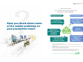
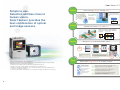
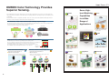
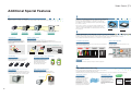
Smart Sensors
with Ultra-High-Speed Color CCD Cameras
ZFV-C
The Next Generation of Advanced Color Sensing.
For Demanding, Color-Critical Applications.
This document provides information mainly for selecting suitable models. Please read the User's Manual (Z240) carefully for information that
the user must understand and accept before purchase, including information on warranty, limitations of liability, and precautions.
Note: Do not use this document to operate the Unit.
OMRON Corporation
Industrial Automation Company
Sensing Devices Division H.Q.
Application Sensors Division
Shiokoji Horikawa, Shimogyo-ku,
Kyoto, 600-8530 Japan
Tel: (81)75-344-7068/Fax: (81)75-344-7107
OMRON ELECTRONICS LLC
1 East Commerce Drive, Schaumburg,
IL 60173 U.S.A.
Tel: (1)847-843-7900/Fax: (1)847-843-8568
Regional Headquarters
OMRON ASIA PACIFIC PTE. LTD.
83 Clemenceau Avenue,
#11-01, UE Square,
239920 Singapore
Tel: (65)6835-3011/Fax: (65)6835-2711
OMRON EUROPE B.V.
Sensor Business Unit,
Carl-Benz-Str. 4, D-71154 Nufringen,
Germany
Tel: (49)7032-811-0/Fax: (49)7032-811-199
OMRON (CHINA) CO., LTD.
Room 2211, Bank of China Tower,
200 Yin Cheng Road (M),
Shanghai, 200120 China
Tel: (86)21-5037-2222/Fax: (86)21-5037-2200
Authorized Distributor:
Note: Specifications subject to change without notice.
Cat. No. E373-E1-02
Printed in Japan
0306-2M (0306) (C)
If you l i sten careful l y,
you'l l probabl y hear peopl e compl ai ni n g
about these sensor probl ems.
Have you heard about some
of the sensor problems on
your production lines?
With optical sensors...
With image sensors...
It's difficult to
make fine settings.
It takes time to
make settings and
adjustments.
They're
expensive.
Detection is
unstable, leading
to quality
problems.
lt's difficult to reset
the line when
products change.
Only people with
technical
knowledge can
operate them.
Optical sensors and image sensors.
The general consensus on the production line is that they both have their advantages and
disadvantages.
Many users hesitate to introduce a full-scale image sensor system, but at the same time, find it
difficult to install and use an optical sensor system.
Now there is a sensor that answers these problems.
Not an optical sensor and not an image sensor, it's a brand new type of smart sensor.
With the increasing importance that is being placed on quality control today,
you will find this sensor to be a major help in moving your production lines forward.
Introducing the new Smart Sensor from OMRON.
Simple to use.
Detection abilities close to
human vision.
Smart Sensor provides the
best combination of optical
and image sensors.
Stability
From sensing points to sensing areas
With optical sensors...
The Color Filter function also
improves contrast for more
stable detection of even faint
text.
The color ZFV
There's a chance they will
fail to detect due to problems
like a shift in the
position of printed
text.
It distinguishes
shapes, so its
measurements
maintain stability.
Freshness date
2009 6 20
Freshness date
2009 6 20
Reliability
Double-check with shape and color
Smart Sensor inspects objects using both
shape and color, the two main criteria used
by people.
Check by shape
Check by color
Simplicity
Set-up is easy, even for first-time users.
Start
setting
TEACH
Menu window
PATTERN
Select inspection item.
MOVE
Specify area
Simple menu selection using icons.
One-touch teaching function
Just select the icon for the application
you want.
The basic settings for inspection items are made by watching
the monitor and simply pressing the appropriate button.
This also speeds up resetting operations when products change.
Finish
setting
Note: The operational flow varies depending on the selected item.
Color or position differences are a good example.
A person can see these with a glance, but it's both costly and labor-intensive to set up a system
that will allow a sensor to detect these differences.
If only there were a simpler way, something that resembled human vision...
Now there is, because we have added color capabilities to the Smart Sensor.
In addition to being able to distinguish colors, the new Smart Sensor also offers stable detection
for ordinary, conventional workpieces.
It goes a long way toward answering many of the problems that today's production lines are facing.
Ease
Easier than image sensors in a variety of ways.
With image sensors...
With smart sensors...
You need to worry about
the initial cost and the
work to build the system.
Start-up is easy because the sensor and the light source are
integrated. Of course, it is also reasonably priced.
You don't need advanced
functions for simple
inspections.
Only the functions that your production people truly need are provided.
By including the essential functions of the image sensor,
we have achieved highly stable measurement.
Settings are complicated
and maintenance is a
chore.
Even new users can make settings and adjustments easily
by selecting the icons while watching the LCD monitor.
You don't have to be an expert to use it.
OMRON Color Technology Provides
Superior Sensing.
The original Smart Sensor was designed to be easy enough for anybody to use, and our color model shares the
Seven HighPattern
same characteristic. The ZFV-C Color Smart Sensor is designed with the same Target, Teach, Go simplicity as the
level Matching
Area
Capabilities
original ZFV.
for a Wide
The Color Filter function is completely automatic, and colors can be easily extracted while watching the monitor.
This sensor is smart enough to handle even advanced applications.
Range of
The Automatic Color Filter function adds stability to your images.
This function increases the image contrast to make measurements more stable. There are a total of seven color filters in all.
Applications
The one that obtains the most suitable contrast is automatically selected,
so there's no need to worry about color setting parameters.
After filtering
Color image
Monochrome image
Cyan
Blue
Green
Crisp and clear!
The optimal filter is
Yellow
automatically
selected.
Red
Gray
Without filtering
Monochrome image
Measure the area of shapes and
compare against model to detect
broken cookies.
Measure difference or presence
of patterns to match shape of
object.
Position
Width
Low contrast
Magenta
HUE
Simply choose the candidate color to complete color extraction.
For items that use color extraction, you simply specify the area you want.
The color components in that area are then analyzed and the extraction color candidates are
automatically displayed. All you have to do is select the color to be measured.
The extraction conditions for the candidate colors can also be fine-tuned if necessary.
This is OMRON's unique human-machine interface for color extraction.
Extraction color
candidates
Measure width between leads.
Measure the edge position of
labels or sheets.
Actual color measurement
Simultaneous, one-touch checking of multiple colors
Inspecting for the intermixture of
different-colored packages
Inspecting for the intermixture of
different cap types
Actual colors can be measured, and those differing
from the reference color can be easily distinguished.
Multiple colors can be extracted, so that the surface area
of each color can be distinguished.
Number
Brightness
Character
(Reference)
Color
Count the number of cookies.
Area
The area of
this color is
different.
The area of
this color is
different.
Detecting dirt on battery
surfaces.
Match entire character string or
detect one missing character.
Additional Special Features
Wider Field of View of 150 mm
Optional Lighting with Easy, One-touch Mounting
With an FOV from 5 to 150 mm, you can inspect even large workpieces that could not be previously handled.
A wide variety of optional Lighting Units are available for when the light
ZFV-SC50@/-SC90@
intensity of the integrated lighting is not sufficient, or when throughbeam lighting or some other lighting method is required. Simply plug in
the connector to add on.
There is also no need for a special power supply for lighting. Plus, the
optional Units feature strobe lighting in sync with the Sensor Head
shutter, to provide stable lighting for an extended period of time and a
long service life.
Light source for throughbeam lighting
Bar-type low-angle lighting
ZFV-LTL04
ZFV-LTF01
Narrow View Type
Standard Type
Wide View Type
Ultra-wide View Type
ZFV-SC10
FOV: 5 to 9 mm
ZFV-SC50@
FOV: 10 to 50 mm
ZFV-SC90@
FOV: 50 to 90 mm
ZFV-SC150@
FOV: 90 to 150 mm
Vision Amplifier with Monitor Features Versatile Functions in a Compact Body
Integrated with a 1.8-inch LCD monitor, this Amp is the same compact size as our monochrome models.
It enables operation while viewing the image, so the measurement status can be checked while the line is moving.
Adjustable View
Optimize Lighting Pattern
Intelligent Lighting
Simple Focus Adjustment
An easy to use, manual focus adjustment on
the camera eliminates the need to change the
head or modify programming for different
workpiece sizes.
It also features USB and RS-232C interfaces for connection to a personal computer.
ZFV-SC10/-SC50@/-SC90@
The lighting pattern can be varied to ensure a uniformly bright display even
when the Sensor Head is mounted at an angle. Also, the light turns in sync with the shutter
operation, for excellent stability and a long service life.
Illuminates with
brighter lights
at the top.
Select auto or manual control.
Illuminates entire surface uniformly.
Quick and Easy Operation
Selectable Display Patterns
Function Keys
One-touch Display Selection
Select the image display that is easiest to see from among color, monochrome,
and color extraction display patterns.
Color image
Color extraction image
Color extraction image
After filtering (red)
Color
Monochrome
Monochrome
Fixed keys are allotted with various functions for easy,
one-touch operation.
Switch the color image display
Sensor
A
B
C
D
Partially dark.
Adjustment control
Dark
Bright
Uniform
Re-measure
Fast Mounting
Multi-mount Bracket
Ultra Fast for High-speed Production Lines
ZFV-SC10/-SC50@/-SC90@
Mounts to either of the four Sensor Head surfaces,
allowing highly flexible mounting and removal.
Change color extraction
Note: Button B is used for function expansion.
High-speed Random Shutter CCD
Japanese-English Selection
Captures images without any blur,
even on high-speed lines. Even at
high shutter speeds, the LED
power is automatically controlled
to provide crisp, clear images.
Multi Menu
The menu can be switched to Japanese or English to match the application.
No blurring
IP67-compliant Design
ZFV-SC90W/-SC150W
Washable Head
Featuring an IP67-equivalent design, these models can
be completely immersed in water for washing. The entire
structure, including the light source, is water resistant.
High-quality Data Transmission
Digital Interface Capability
The image captured by the Sensor Head is quickly
transmitted in digital format, making it immune to noise.
High-speed Color Processing
The processing speed is approximately the same as that for monochrome,
even when detecting color images with high precision.
OMRON's image processing technologies remove the usual hesitation to use color processing due to its reduced efficiency.
The Industry's Fastest
Even Faster — 5 ms
Real-time Search
Digital transmission
An original CCD drive technology
and image processing engine
enable ultra-fast response by
processing data as the image is
being captured.
The actual image processing time
thus becomes zero, making the total
processing speed 13 ms maximum.
Partial Capture Function
Max. speed
13 ms
The processing speed can be
further increased by limiting the
image capture to only the part that
is required for inspection.
Processing requires 8 ms in FAST
mode, and 5 ms (max. speed) in
MAX mode.
Max. speed
5 ms
Note: FAST mode
Excellent Expandability Meets Even More Applications
With today's rapid pace of new product development, it is essential to select sensors that have future expandability.
The Smart Sensor provides the same level of quality control as larger sensor systems, thanks to its newly enhanced application
capabilities and data management and analysis.
■Models
Sensor Heads
Flexible Combinations
Appearance
High-speed Digital Bus Connection
Controllers can now be directly connected to
prevent delays in response. By altering the
connection, multiple areas can be
simultaneously processed, measurement
items can be combined, and the output from
two Sensor Heads can be integrated.
This also provides sufficient response to
future workpiece changes.
Ordering Information
Basic connection
Convenient for Personal Computer
Operation and Management
Result integration connection
Expanded application connection
Type
Sensing area
Model
34 to 49 mm (variable)
5 × 4.6 mm to 9 × 8.3 mm (variable)
ZFV-SC10
Standard
31 to 187 mm (variable)
10 × 9.2 mm to
50 × 46 mm (variable)
ZFV-SC50 (IP65)
ZFV-SC50W (IP67)
Wide View
66 to 141 mm (variable)
50 × 46 mm (H × V) to
90 × 83 mm (H × V)
ZFV-SC90 (IP65)
ZFV-SC90W (IP67)
Ultra-wide View
114 to 226 mm (variable)
90 × 83 mm (H × V) to
150 × 138 mm (H × V)
ZFV-SC150 (IP65)
ZFV-SC150W (IP67)
Composite connection
Amplifier Units
Smart Monitor ZFV
Support Software
Appearance
Smart Monitor ZFV Support Software
This software allows settings and image data to be
saved and loaded with a personal computer.
For details on the Smart Monitor ZFV Support
Software, please contact your OMRON
representative.
Setting distance
Narrow View
Power supply
Output type
Model
NPN
ZFV-CA40
PNP
ZFV-CA45
24 VDC
USB
Accessories
Data Storage Units
Easy Operation Achieved by Considering the Operator's Viewpoint
Appearance
Power supply
Output type
Model
NPN
ZS-DSU11
PNP
ZS-DSU41
In addition to offering easy basic operation, the ZFV has been designed to provide the best possible
operation in a variety of situations.
It helps your quality control system evolve and become smarter by allowing machines to handle the bothersome tasks.
Handy for Maintenance
Visually Check Judgment Settings
I/O Monitor Function
The parallel I/O status
can be displayed on
the monitor to simplify
wiring checks, to
make maintenance
and system start-up
faster and easier.
Adjustment Mode
Judgment settings are displayed in bar
format, so judgment conditions can be
intuitively set.
24 VDC
Flexible Controller Installation
Flexible installation meets the specific needs
of each production line. In addition to DIN
rail mounting, installation is easy in control
panels.
Controller Link Unit
Panel-mounting Adapter
Model
Appearance
Appearance
Model
SEARCH
ZS-XCN
ZS-XPM1
First Unit
ZS-XPM2
Additional Units
(for expansion)
Sensor Head Extension Cable
Extend the Service Life
ECO Mode
3m
When not in use, the LCD backlight is automatically
turned OFF. This greatly extends the service life
compared with having the backlight constantly ON.
Panel Mounting Adaptor
(Purchase separately)
This function enables easy one-button teaching,
using an image of an instantaneous event that
was captured with an external trigger.
Model
3m
ZFV-XC3BV2
ZFV-XC8BRV2
(Robot cable type)
8m
ZFV-XC8BV2 (See note 1.)
A maximum of two Extension Cables can be connected to extend the cable length of each Sensor Head.
There are no restrictions on the combinations of the two Extension Cables to be used.
Note 1: The ZFV-XC8BV2 Extension Cable can be used only with ZFV-SC10/SC50/SC50W Sensor Heads.
Versatile Teaching Modes
Freeze-screen Teaching
Cable length
TH
Workpiece-movement Teaching
The optimum lighting can be automatically selected
by using an external trigger to input an image of a
moving workpiece.
External Lighting
Type
Appearance
Model
Bar Lighting
ZFV-LTL01
Bar Double Lighting
ZFV-LTL02
Bar Low-angle Lighting
ZFV-LTL04
Light Source for Through-beam Lighting
ZFV-LTF01
Specifications
■Amplifier Units
■Sensor Heads
Item
ZFV-SC10
ZFV-SC50/SC50W
(Narrow View Type)
(Standard Type)
(Wide View Type)
(Ultra-wide View Type)
Output method
34 to 49 mm
(variable)
Setting distance (L)
Sensing range (H × V)
5 × 4.6 mm to
9 × 8.3 mm
(variable)
31 to 187 mm
(variable)
67 to 142 mm
(variable)
10 × 9.2 mm to
50 × 46 mm
(variable)
50 × 46 mm to
90 × 83 mm
(variable)
115 to 227 mm
(variable)
Serial I/O
90 × 83 mm to
150 × 138 mm
(variable)
Setting distance (L)
Setting distance (L)
Setting distance (L)
49 mm
187 mm
142 mm
227 mm
34 mm
31 mm
67 mm
115 mm
9 mm
Sensing range (H)
Built-in lens
Focus: f15.65
Object lighting method
Pulse lighting
Object light source
Eight white LEDs
50 mm
50 mm
Sensing range (H)
90 mm
90 mm
Sensing range (H)
Focus: f13.47
Focus: f6.1
Thirty-six white LEDs
Twenty white LEDs
No
Optional lighting interface
Sensing element
10 mm
Sensing range (H)
Yes
No
Full screen
Resolution
468 × 432 (H × V) max.
Bank selection
Supported for 8 banks.
Image input cycle
13 ms (Standard), 8 ms (FAST mode), 5 ms (MAX mode)
Other functions
Control output switching: ON for OK or ON for NG, ON delay/OFF delay, One-shot output, "ECO" mode
15 VDC, 48 VDC (Supplied from Amplifier Unit.)
Approx. 200 mA
Approx. 350 mA (15 V: approx. 150 mA, 48 V: approx. 200 mA,
including current when external light is connected)
Output signals
1,000 VAC, 50/60 Hz for 1 min
Vibration resistance (destruction)
10 to 150 Hz, 0.35-mm single amplitude, 10 times each in X, Y, and Z directions for 8 min
2
Shock resistance (destruction)
150 m/s , three times each in six directions (up/down, left/right, forward/backward)
Ambient temperature range
Operating: 0 to 40°C, Storage: −20 to 65°C (with no icing or condensation)
Ambient humidity range
Operating and storage: 35% to 85% (with no condensation)
Ambient atmosphere
Must be free of corrosive gas.
Connection method
Prewired, Standard cable length: 2 m
Degree of protection
(IEC 60529 standard)
IP65
Materials
Case: ABS, Mounting bracket: PBT
ZFV-SC@@@: IP65
ZFV-SC@@@W: IP67
Approx. 200 g
(including mounting
bracket and cord;
packaged condition:
approx. 300 g)
Approx. 270 g
(including mounting
bracket and cord;
packaged condition:
approx. 350 g)
Approx. 300 g
(including mounting
bracket and cord;
packaged condition:
approx. 380 g)
Approx. 600 g
(including mounting
bracket and cord;
packaged condition:
approx. 780 g)
Mounting bracket
(ZFV-XMF) (1),
Ferrite core (2),
Instruction sheet
Mounting bracket
(ZFV-XMF2) (1),
Ferrite core (2),
Instruction sheet
Mounting bracket
(ZFV-XMF2) (1),
Ferrite core (2),
Instruction sheet
Ferrite core (2),
Instruction sheet
Class 1
ZFV measurement cycle (See note 1.)
Logs up to 128 images in series
15 max. (ZFV: 5 Units max.)
Amplifier Unit setting data can be saved to the memory card as bank data.
Reading bank data enables bank switching.
(1) Control output (OUTPUT) (2) Enable output (ENABLE) (3) Error output (ERROR)
(2) Bank selection input (BANK1-3)
(3) Object stationary teaching (TEACH)/Object motion teaching (TEACH); switched from menu
Dielectric strength
Note :
External bank
function
Stores NG images or all images.
(1) Sync measurement input (TRIG)/Continuous measurement input (TRIG); switched from menu
Power supply voltage
LED class (See note.)
Sampling rate
Connecting
Number of logged images
to ZS-DSU
(See note 2.) Number of connected Units
Input signals
15 VDC
(Supplied from
Amplifier Unit.)
Accessories
1 port, 115200 bps max.
Sensing area
1/3-inch CCD
Electronic shutter, shutter time: 1/500 to 1/8,000
Weight
1 port, full-speed (12 Mbps) MINI-B
RS-232C
• Patterns (PATTERN), Brightness (BRIGHT): Any rectangular area (256 × 256 max.)
• Area (AREA), Width (WIDTH), Position (POSITION), Count (COUNT),
Color inspection (HUE), Character (CHARA): Any rectangular area (full screen max.)
Seventy-two white LEDs
Shutter
Current consumption
150 mm
USB2.0
Teaching area size
Image logging trigger
5 mm
ZFV-CA45
PNP open collector, 50 mA max.,
residual voltage 1.2 V max.
Patterns (PATTERN), Brightness (BRIGHT), Area (AREA), Width (WIDTH),
Position (POSITION), Count (COUNT), Color inspection (HUE), Character (CHARA)
(H)
Setting distance (L)
NPN open collector, 30 VDC 50 mA max.,
residual voltage 1.2 V max.
Inspection items
Sensing range (V)
Relation between setting
distance and sensing range
ZFV-CA40
Item
ZFV-SC90/SC90W ZFV-SC150/SC150W
Class 2
Applicable standards
IEC 60825-1: 1993, +A1: 1997, +A2: 2001, EN 60825-1: 1994, +A1: 2002, +A2: 2001
Class 2
Class 1
Sensor Head interface
Digital interface
Image display
TFT 1.8-inch LCD (Display dots: 557 × 234)
Indicators
• Judgment result indicator (OUTPUT, Color: orange) • Inspection mode indicator (RUN, Color: green)
• Error indicator (ERR, Color: red) • Ready status indicator (READY, Color: blue)
Operation interface
• Cursor keys (up, down, left, right) • Setting key (SET) • Escape key (ESC)
• Operating mode switching (slide switch) • Menu switching (slide switch)
• Teaching/Display switching key (TEACH/VIEW) • Function keys (A to D, 4 inputs)
Power supply voltage
20.4 to 26.4 VDC (including ripple)
Current consumption
800 mA max. (with Sensor Head connected)
Dielectric strength
1,000 VAC, 50/60 Hz for 1 min between leads and Amplifier Unit case
Noise immunity
1 kV, Pulse rise: 5 ns, Pulse width: 50 ns, Burst duration: 15 ms, Cycle: 300 ms
Vibration resistance (destruction)
10 to 150 Hz, 0.1-mm single amplitude, 10 times each in X, Y, and Z directions for 8 min
Shock resistance (destruction)
150 m/s , three times each in six directions (up/down, left/right, forward/backward)
Ambient temperature range
Operating: 0 to 50°C, Storage: −25 to 65°C (with no icing or condensation)
Ambient humidity range
Operating and storage: 35% to 85% (with no condensation)
Ambient atmosphere
Must be free of corrosive gas.
Degree of protection
IEC 60529, IP20
Materials
Polycarbonate
Weight
Approx. 300 g (including cord; packaged condition: 450 g)
Accessories
Ferrite core (1), Instruction sheet
2
Note 1: This is the sampling rate when logging images. To log measurement data only, use the ZS-DSU settings.
2: Connection with the ZS-DSU will be possible with a future upgrade.
Dimensions
(Unit: mm)
■Sensor Heads
1/4-20UNC
Depth: 6
■Amplifier Units
34
20
ZFV-SC10
18.7
ZFV-CA4@
34
23.2
33.6
30.
30.1
52.50
60
4.61
Two, M4
Depth: 6
Mounting Hole Dimensions
90
20±0.1
Mounting Bracket can be attached to any side.
0.8
32
Focus adjustment dial
5.6
67.90
Two, M4
33
17.9
30
Heat-resistive vinyl-insulated cable
5.8 dia, standard length: 2 m
4.5 4.5
4.30
6.36
3.90
4.5
33.6
32
13 10
30
0
4
4.5
10.80
6.36
8.5
32.90
12.8 dia.
23.30
24.20
ZFV-SC50/SC50W
34
26.5
11.7 dia.
1/4-20UNC
Depth: 6
34
20
18
■Optional Lighting
38.9
ZFV-LTL01
Two, M4
Depth: 6
ZFV-LTL04
30.1
Mounting Hole Dimensions
34
Mounting Bracket can be
attached to any side.
20±0.1
Two, M4
100±0.1
86
52.5
5.6
26.5
Heat-resistive vinyl-insulated
cable 6.2 dia,
standard length: 2 m
62
5.2
3
±0.1
(6
20
39
52.5
5
8.5
6.2 dia.
8
3
5
P5.8 × 9 = 52.2
Four, M4
(through-hole)
Two sets of three, M3
Depth: 5
Mounting Hole Dimensions
33
165.4
140
37.4
3.2
90°
59.9
9.8
30.3
+100
0
2000
33
34
ZFV-SC90/SC90W
±0.1
20
14
20±0.1
1/4-20UNC
Depth: 6
34
20
8
29
10.7
20
Mounting Hole Dimensions
85
165.4
350 +35
0
85
62
140 100
P5.8 × 9 = 52.2
38.9
Two, M4
Depth: 6
30.1
20±0.1
33
Tw
o
,M
4
±0.1
Two, M3
Depth: 5
69
74
20
Mounting Hole Dimensions
20
20
83.7
Mounting Hole Dimensions
33
9.8
52.5
2000
20
35.5
4
6.2 dia.
39
35.5
5.6
30.25
52.5
100
+100
0
Heat-resistive vinylinsulated cable 6.2 dia,
standard length: 2 m
Mounting Bracket can be
attached to anyy side.
ZFV-LTL02
ZFV-LTF01
8.5
8.5 8.5
7
±0.1
110.2
59.5
74±0.1
±0.1
ZFV-SC150/SC150W
Mounting Hole Dimensions
74±0.1
140
Four, M4
(through-hole)
29
5
33
350 +35
0
140
3.2
1
90°
103
59.9
22
(light-emitting
mitting surface)
8.5
4
Mounting Hole Dimensions
74
20
140
35
Mounting
surface
57
Two, M4
98
Heat-resistive vinyl-insulated
cable 6.2 dia,
standard length: 2 m
70
109 (light( light-
85
165.4 140 100
7
8.5
emitting
emittin
surfac
surface)
P5.8 × 9 = 52.2
33
20
20
62
20±0.1
Mounting Hole Dimensions
20
2000+1000
100
20
74
+100
0
12
85
8.5
8.5
2000
73.2
Four, M3
Depth: 8
Smart Sensors
with Ultra-High-Speed Color CCD Cameras
ZFV-C
The Next Generation of Advanced Color Sensing.
For Demanding, Color-Critical Applications.
This document provides information mainly for selecting suitable models. Please read the User's Manual (Z240) carefully for information that
the user must understand and accept before purchase, including information on warranty, limitations of liability, and precautions.
Note: Do not use this document to operate the Unit.
OMRON Corporation
Industrial Automation Company
Sensing Devices Division H.Q.
Application Sensors Division
Shiokoji Horikawa, Shimogyo-ku,
Kyoto, 600-8530 Japan
Tel: (81)75-344-7068/Fax: (81)75-344-7107
OMRON ELECTRONICS LLC
1 East Commerce Drive, Schaumburg,
IL 60173 U.S.A.
Tel: (1)847-843-7900/Fax: (1)847-843-8568
Regional Headquarters
OMRON ASIA PACIFIC PTE. LTD.
83 Clemenceau Avenue,
#11-01, UE Square,
239920 Singapore
Tel: (65)6835-3011/Fax: (65)6835-2711
OMRON EUROPE B.V.
Sensor Business Unit,
Carl-Benz-Str. 4, D-71154 Nufringen,
Germany
Tel: (49)7032-811-0/Fax: (49)7032-811-199
OMRON (CHINA) CO., LTD.
Room 2211, Bank of China Tower,
200 Yin Cheng Road (M),
Shanghai, 200120 China
Tel: (86)21-5037-2222/Fax: (86)21-5037-2200
Authorized Distributor:
Note: Specifications subject to change without notice.
Cat. No. E373-E1-02
Printed in Japan
0306-2M (0306) (C)