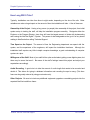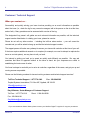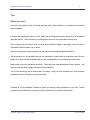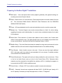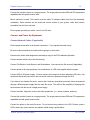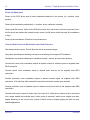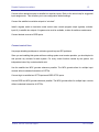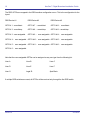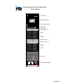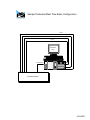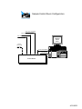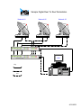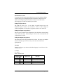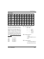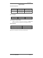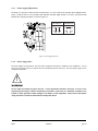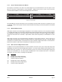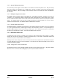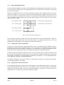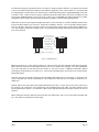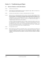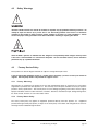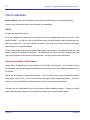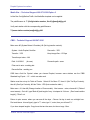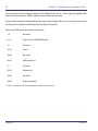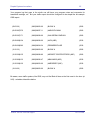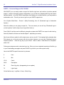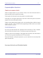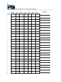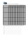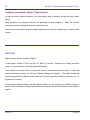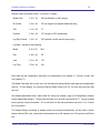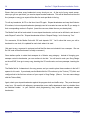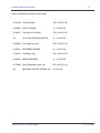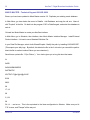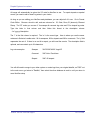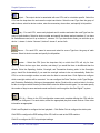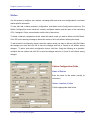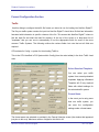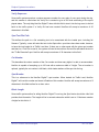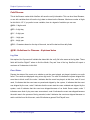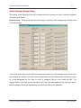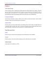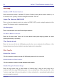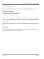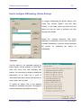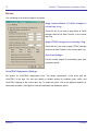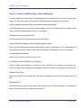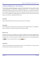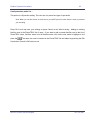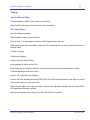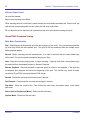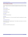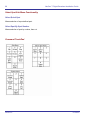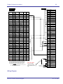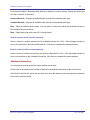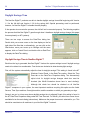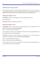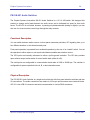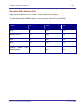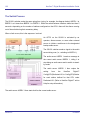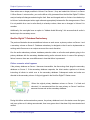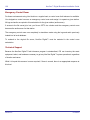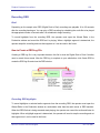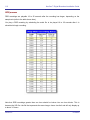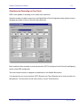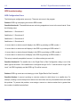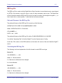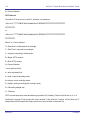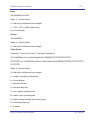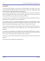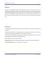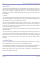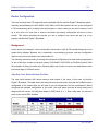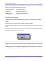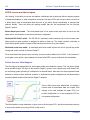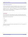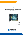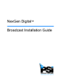
1
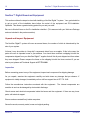
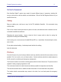
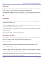
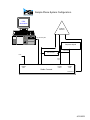
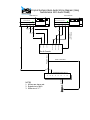
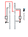
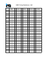
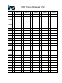
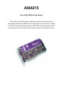
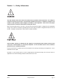
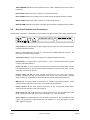
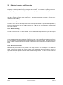
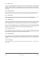
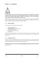
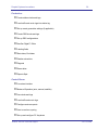
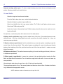
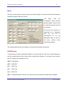
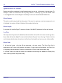
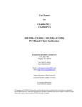
NexGen Digital™
Broadcast Installation Guide
COPYRIGHT
© 2000-2002 Prophet Systems Innovations
P.O. Box 887, Ogallala, Nebraska, 69153, USA.
All rights reserved.
No part of this publication may be reproduced in any form
without written permission.
This publication is provided without warranty of any kind,
implied or expressed, including but not limited to, the
implied warranties of merchantability and fitness for a
particular purpose, and the correctness of data in this
guide.
Prophet Systems Innovations may make improvements or
changes in the products and programs described in this
document at any time.
www.prophetsys.com
Table of Contents
Introduction ................................................................................. 1
How Long Will it Take? ............................................................................................ 3
Customer Support .................................................................................................. 4
Tips ........................................................................................................................ 5
Pre-Installation Checklist.......................................................................................... 7
Equipment Set-Up....................................................................... 9
Unpack and Inspect................................................................................................. 10
Set Up Equipment ................................................................................................... 11
Power Up Equipment .............................................................................................. 14
Site Diagrams ............................................................................. 17
Supplier Guides .......................................................................... 19
Traffic and Music ........................................................................ 21
Traffic ..................................................................................................................... 22
MediaStar............................................................................................................ 23
CBSI ................................................................................................................... 23
DARTS ................................................................................................................ 26
Programming and Music .......................................................................................... 27
Selector .............................................................................................................. 28
Music Master ....................................................................................................... 32
Training ....................................................................................... 35
Program the Database............................................................................................. 36
Training Checklist.................................................................................................... 39
This page left blank intentionally.
Prophet Systems Innovations
1
Introduction
Introductory information, Customer Support contact numbers, and
Pre-Installation Checklist.
24-Hour Toll Free Technical Support
877.774.1040
2
NexGen™ Digital Broadcast Installation Guide
Welcome
Thank you for choosing a Prophet Systems Innovations (PSi) NexGen Digital™Broadcast system.
The Installation Guide is intended to be a resource for the station
engineer and the production (or music) director at the initial stage to
successfully set up the NexGen Digital™Broadcast system.
After the initial set up, a Prophet Systems Installation Specialist will
come on site and train the staff to begin using the NexGen
Digital™Broadcast system.
The Installation Guide is generally straightforward; however, if you have any questions or require
assistance, please call our Technical Support Department at 877.774.1040.
Additional Technical Documentation is available at http://www.prophetsys.com/products/techinfo.
Here you will find NexGen Digital™ User Documentation, our Technical White Paper Series, and cable diagrams.
What you will find in this guide…
Equipment Set-Up and Configuration
Unpack, inspect, and set up equipment. Includes sample and site-specific diagrams.
Supplier Information
User Guides for audio card, PCI card, and audio control unit.
Traffic and Music
Set up information for the most common Traffic and Music systems with NexGen Digital™.
Training and Configuration
Training on the NexGen Digital™ software set up and use by the PSi Installation Specialist.
CD/Extractor (CD/X) and Audio Format Converter (AFC) User Guides
Revision A
4/15/2002
Prophet Systems Innovations
3
How Long Will It Take?
Typically, installations can take from three to eight weeks, depending on the size of the site. Other
variables can make a large impact on the amount of time the installation will take. A few of these are:
Ownership of the Project: Having a key person (or people) take ownership of the project, from initial
system setup to training the staff, will help the installation progress smoothly. Designate either the
Engineer or the Program Director, since they will have the largest amount of duties with implementing
and running the NexGen Digital™ System. This person is also designated as the ‘go-to’ for any issues
relating to NexGen before calling Technical Support.
Time Spent on the Project: The amount of time the Engineering department can spend with the
system, and the experience of the engineers, will impact the installation timeframe. Although the
installation itself requires very little in-depth computer knowledge, a good understanding of computer
systems is a plus.
Willingness of the Staff: Most of your staff will be quite excited about getting a new digital system, but
there may be some that aren’t. Be aware of the staff’s feelings toward this project and adjust your
expectations accordingly.
Audio Recording: A good rule is to take the amount of audio length that needs to be recorded and
double it. This allows for typing in database information and recording the spot or song. (This timeframe can be greatly reduced by using pre-stored music).
Other Projects: Be sure to include any additional equipment upgrade or remodeling projects into the
expected NexGen install time frame.
24-Hour Toll Free Technical Support
877.774.1040
4
NexGen™ Digital Broadcast Installation Guide
Customer / Technical Support
When you contact us…
Successfully and quickly solving your issue involves providing us as much information as possible
about the issue (i.e., check the log for any unusual messages, talk to the person on the air at the time,
and so forth). Many questions can be answered with a review of the log.
The designated ‘key person’ will gather as much relevant information as possible, call the technical
support number listed below. In relating your issue, please be concise.
Please do not call any other number – including the toll-free sales number – your call cannot be
rerouted and you will be asked to hang up and dial the technical support number.
The support person will make every attempt to answer your issue with a solution at the time of your call.
If the issue requires additional research or is complex (for example, we need to attempt to replicate the
issue on our test system), we may have to call you back.
Our interest is getting you back up to speed as quickly and efficiently as possible. We may ask
questions that have no apparent relation to the issue at hand, but your responses are critical to
establishing the best course of action.
Our focus is always to work with you to arrive at a solution, regardless of the cause, and get you up and
running as soon as possible.
Please use the following numbers for issues involving customer and technical support services*.
Toll Free Technical Support: 1-877-774-1040
Fax: 308-284-2382
Prophet Systems Innovations, P.O. Box 887, Ogallala, NE 69153
[email protected]
Daryl Webster, Senior Manager of Customer Support
Toll Free: 1-877-774-1010
Direct: 1-308-284-5028
Fax: 308-284-4181
[email protected]
*If you are outside the United States, please contact your NexGen Digital™ supplier for support procedures.
Revision A
4/15/2002
Prophet Systems Innovations
5
Tips
Before you start…
Here are some cautions, tips, and tricks that have been often brought to our attention from previous
implementations.
Complete the Installation Guide up to the Training and Configuration section before the PSi Installation
Specialist arrives. This will ensure your staff gets the most out of the scheduled training time.
Plan to operate the old system until you have tested NexGen Digital™ thoroughly. Once the staff is
comfortable with the system, go on the air.
Leave your old system up as a backup until the staff is comfortable with NexGen Digital™.
We recommend you not advertise that you are switching to a new format on a particular date. Run the
system for a while and then advertise that you are switching after you are already up and running.
Never switch on the air right before a holiday. There are many other distractions during a holiday – you
and your staff will need to keep focused during the transition.
This is new technology and a different way of working - after you have switched over, have someone
scheduled to watch it closely for at least one week.
Following is a Pre-Installation Checklist to guide you through initial preparation of your site. Please
complete this checklist before continuing to the Equipment Set-Up section of this guide.
24-Hour Toll Free Technical Support
877.774.1040
6
NexGen™ Digital Broadcast Installation Guide
This page left blank intentionally.
Revision A
4/15/2002
Prophet Systems Innovations
7
Preparing for NexGen Digital™ Installation
¨ Wall Space
- Have wall space behind racks prepared (preferably with plywood backing) for
mounting of pre-wired 66 punch blocks.
¨ Racks - Racks must be 19” rack enclosures. Power strips should be mounted outside of the rear
rail.
We recommend Middle Atlantic WRK-44-32 Rack Enclosures with the WRK-RR44
Additional Rail Kit (44 Space).
¨ Power - A 20-amp dedicated circuit for each rack should be wired to an outlet or power strip.
¨ Modem Line - Technical Support uses remote access software to
‘dial-in’ for online training,
upgrading the system, and troubleshooting. You need to have a dedicated modem line in place
for this purpose.
¨ Audio Cable –There should be 13 stereo audio cables to each air studio, and 5 stereo audio
cables to each production room. The cable should be pre-run to all studios and punched down
to any in-studio blocks. Use Multi-Pair/Dual-Pair Broadcast Cables, 24 AWG.
¨ Satellite Wiring – The Audio Cable should also be readied for wiring audio and closures from the
satellite receivers to the rack area for delayed broadcast feeds or live satellite switching.
¨ Tone Decoder - Verify all audio sources to be used.
If there are more than eight, additional
ACU-1 units may need to be ordered to accommodate all of your sources. If needed, purchase
a tone decoder for all satellite sources.
¨ Control Board Inputs - The system will need up to 8 play modules for each control area.
(Three
or four for the Audio Server, and up to four for the Control Room CPU) Determine which
networks must be connected to the satellite box switchers (ACU-1), including the programs to
be recorded by the DRR. Confirm satellite sources.
¨ Control Cable – A 25-pair, CAT 5 trunk cable is needed for remote start and stops.
¨ HVAC – Generally, the rack room equipment will draw 20,000 - 30,000 Btu load. Usually a 2-3
ton AC capacity is necessary to keep the equipment at, or below, 72 degrees F.
24-Hour Toll Free Technical Support
877.774.1040
8
NexGen™ Digital Broadcast Installation Guide
This page left blank intentionally.
Revision A
4/15/2002
Prophet Systems Innovations
9
Equipment Set Up
Unpack, inspect, and set up the NexGen Digital™ equipment.
24-Hour Toll Free Technical Support
877.774.1040
10
NexGen™ Digital Broadcast Installation Guide
NexGen™ Digital Broadcast Equipment
This section outlines the steps involved with installing a NexGen Digital™ system. Your goal should be
to get as much of the installation done before the arrival of the equipment and PSi Installation
Specialist. This allows a greater training period for you and your staff.
Be sure to finish all items on the Pre-Installation checklist. (This was sent with your Welcome Package
and was included in the previous section).
Unpack and Inspect Equipment
The NexGen Digital™ system will come as several boxes, the number of which is determined by the
size of your system.
At times it may be quicker to “drop ship” components direct from our supplier. If this is the case, the
parts will come in separate boxes to your address. You should have received a shipping list with the
components shipped from your NexGen Digital™ supplier that will list all parts shipped and from where
they were shipped. Please compare the items on the shipping list with the items received. If you are
short a part, please call Technical Support at 877.774.1040.
Inspection
Before connecting power to any of the equipment, inspect each component for shipping damage.
As you unpack, examine the equipment carefully and write down any damage that you observe. If
equipment is visibly damaged, immediately call our toll-free support line at 877.774.1040.
Follow the manufacturer instructions enclosed with the equipment.
The internal components are
sensitive to and can be damaged by electrostatic discharge.
Check screws and electrical components inside the boxes and the equipment. If there are any loose
parts, call technical support.
Ensure cards are seated firmly inside computers.
Save all manuals, warranty cards, boxes and original packing.
Revision A
4/15/2002
Prophet Systems Innovations
11
Set Up the Equipment
Each NexGen Digital™ system may consist of several different types of computers, including file
servers, audio servers, real time editors, and workstations. Refer to the Site Diagrams Section for your
specific site set-up.
Cabling
Map your cabling runs, and keep a copy for the PSi Installation Specialist. We recommend using
shielded cable.
Plan out the control board inputs that the system will need, and determine which networks must be
connected to satellite box switchers.
Determine the source location.
Leave at least six feet of excess cable to allow for moving the
equipment for testing and troubleshooting.
Avoid running over or near sources of notable EMI and RFI (i.e., transmitters, fluorescent lights, motors,
and so forth).
Do not splice network cabling. Avoid sharp bends that kink the cabling.
Label all cable ends.
File Server
Once the file server is up and running it seldom needs any attention and should be secured as much as
possible. Put it into a safe, cool, and clean location. Network switches should be located adjacent to
the file servers for monitoring and emergency reassignment.
The file server location must contain a working phone within five feet of the servers. The phone must be
capable of making outgoing long distance calls.
The environment needs to be static free and as stable as possible in temperature and humidity.
The hard drives need to be on a stable and static free surface. Do not locate them near printers.
The location should accommodate easy access to the sides, front, and back panels for emergency
servicing.
24-Hour Toll Free Technical Support
877.774.1040
12
NexGen™ Digital Broadcast Installation Guide
Audio server
Put the audio server close to your audio chain. Once it is up and running, it seldom needs any attention.
It does not need to be in your control room—an audio rack is a good place for it.
Most stations put the audio server next to the file server. The UPS (Uninterruptible Power Supply)
included with the system for the file server is configured to be big enough to handle the audio server as
well.
Control Room
If your control room needs to run in manual mode at times, you will need a workstation to allow you to
manually control the audio server.
Place the computer in the studio where it can get adequate ventilation and where you can have easy
access to the CD-ROM if CD/Extractor is to be used.
If access to the CD-ROM is not necessary, you may desire KVM extenders to relocate the computer
outside of the studio.
Place it away from being in direct line of any microphones.
Digital Reel-to-Reel (DRR)
Place the DRR in the room where the switch can get access to all of the audio sources that will be
brought in for recording. Usually, the DRR is placed close to the audio servers.
Real Time Editor (RTE)
Place the RTE in the room where you will be doing the editing, and where CD/Extractor is used.
NexGen Digital™ Workstation
Workstations can be located many different places – please consult your site diagrams to see where
the purchaser of the system wanted the workstation placed.
Position monitors at least two feet away from any audio wires or audio source. Monitors produce high
frequency noise that can be picked up by your audio wires.
Revision A
4/15/2002
Prophet Systems Innovations
13
Connect the monitor’s power to a surge protector. The surge protectors have EMI and RFI suppression
capabilities that will greatly reduce noise.
Mount switchers in racks. The location must be within 35 (dressed cable) feet from the associated
workstation. Since switches are the audio and control centers of your system, make their location
accessible from the front and back.
Ensure proper grounding on audio, control, and AC lines.
Connect and Power Up Equipment
Connect Network Cables (if applicable)
Ensure proper termination of all network connections. Try to spread the loads evenly.
Be sure to label all switches and network lines going to or from them.
Document the switch load assignments and keep a copy for the PSi Installation Specialist.
Connect network switch (es) to the file server(s).
Connect File Servers, Audio Servers, and Workstations. Inter-connect the file servers (if applicable).
Connect power to all surge protectors, line conditioners, or UPS units supplied with the system.
Connect UPS to AC power supply. Connect servers and computers to their respective UPS units. Any
equipment that directly connects to the servers will need to be powered through the UPS.
If you have a hot standby file server, ensure that it and any associated (external) drives are powered
through a different power supply than the main file server. This will limit the possibility of bringing both
servers down with the loss of a single power supply.
Connect monitors, keyboard, mouse, and other peripherals. (i.e., drives, modems, switches)
Connect the monitor’s power to a surge protector. The surge protectors have EMI and RFI suppression
capabilities that will greatly reduce noise.
Connect the printer to the main file server. Do not connect any printers to the UPS. Printers cause a
UPS to drain very quickly and are not mission-critical during a power failure.
24-Hour Toll Free Technical Support
877.774.1040
14
NexGen™ Digital Broadcast Installation Guide
Power Up Equipment
Power up the SCSI drives and all other peripherals attached to the servers (i.e., monitors, hubs,
printers).
Power up the workstation peripherals (i.e., monitors, drives, switchers, modems).
Power up the file servers. Watch for the SCSI drive count, IDs, and errors in the boot-up process. Once
the file server has reached the network monitor screen, the file server should be ready for workstations
to log in.
Power up the workstations. Watch for boot process errors.
Connect Audio Lines to Workstations and Audio Servers
Start with production rooms. This will allow the dub-in processes to begin.
Use proper grounding and shielding techniques to minimize ground loop and RFI problems.
Workstations can provide a balanced or unbalanced output – be sure to interconnect properly.
Connect the control room workstation outputs to desired console or switcher inputs via supplied male
DB-9 connection.
Connect control room workstation inputs to desired audio sources via the supplied male DB-9
connectors.
Connect production room workstation outputs to desired console inputs via supplied male DB-9
connectors. A full real-time editor workstation requires four discrete console input channels.
Connect production room workstation inputs to desired console bus feed via the supplied male DB-9
connectors.
Connect audio server outputs to switch input (use input # 2). Audio server outputs must be sub-mixed
into a single satellite box switcher input. Active mixing is required if audio server outputs must also
appear discretely on the control room console. Passive mixing or simple ganging will work for most
satellite applications.
Revision A
4/15/2002
Prophet Systems Innovations
15
Connect other desired sources to satellite box switcher inputs. Refer to the online help for suggested
input assignments. This will allow you to use configuration default settings.
Connect the satellite box switcher outputs to “air chain”.
Install a bypass switch to hard-wire routed control room console program output (typically, switcher
input #1) to satellite box outputs. A bypass route must be available, to allow for switcher maintenance.
Connect desired sources to DRR inputs.
Connect control lines
Use proper shielding techniques to minimize ground loop and RFI problems.
Since you are installing this system while an existing system must remain operative, you should plan for
and provide dry contacts for each system. For every control function needed by the system, two
independent sets of dry contacts should exist.
Use the satellite box MPX grounds whenever possible. The MPX grounds allow for multiple input
controls without undesired interaction of OPTOs.
Connect logic to satellite box OPTO inputs and DRR OPTO inputs.
Use the DRR box MPX grounds whenever possible. The MPX grounds allow for multiple input controls
without undesired interaction of OPTOs.
24-Hour Toll Free Technical Support
877.774.1040
16
NexGen™ Digital Broadcast Installation Guide
The DRR OPTOs are mapped in the DRR machine configuration menu. This is the configuration for the
layout:
DRR Device #1
DRR Device #2
DRR Device #3
OPTO # 1 - record/start
OPTO # 7 - record/start
OPTO #12 - record/start
OPTO # 2 - record/stop
OPTO # 8 - record/stop
OPTO #13 – record/stop
OPTO # 3 - user-assignable
OPTO # 9 - user-assignable OPTO #14 - user-assignable
OPTO # 4 - user-assignable OPTO #10 - user-assignable OPTO #15 - user-assignable
OPTO # 5 - user-assignable OPTO #11 - user-assignable OPTO #16 - user-assignable
OPTO # 6 - user-assignable
Note that the user-assignable OPTOs can be assigned as any one type from the following list:
Liner A
Liner B
Liner C
Liner D
Liner E
Liner F
Liner G
Legal ID
Spot Block
If multiple DRR switches are used, all OPTOs will be received only through the first DRR switch.
Revision A
4/15/2002
Prophet Systems Innovations
17
Site Diagrams
Sample and Site-Specific Diagrams for NexGen Digital™ Equipment
24-Hour Toll Free Technical Support
877.774.1040
18
NexGen™ Digital Broadcast Installation Guide
This page left blank intentionally.
Revision A
4/15/2002
Sample Rack Mount Configuration
(One Station)
D
S
I SCO
C
SY S T E M S
Cisco Switch
Rackmount Monitor
Rackmount Keyboard
A
B
C
D
E
F
G
H
KVM Switch
SELE CTED
ON- LI NE
DRR-1 ACU-1-1
DRR-1 ACU-1-2
DRR-1
PROD-1
ASERV-1 ACU-1-1
ASERV-1 ACU-1-2
ASERV-1
CTRL-1
D
S
H EWL ETT
P AC KA R D
N et Serve r LH 3r
File Server
p
. en. ti. um
..
D
S
Smar t -U PS
Test
Universal Power Supply
1 4 0 0
ME R IC A N P OWE R C ON V
A
E R S IO N
7 FOOT RACK
4/15/2002
This page left blank intentionally.
Sample Production/Real Time Editor Configuration
Track #4
Track #3
Track #2
Track #1
Production/
RTE
RECORD INPUT
Production Board
4/15/2002
This page left blank intentionally.
Sample Control Room Configuration
Audio Server Playback #1
Audio Server Playback #2
Audio Server Playback #3
CONTROL
ROOM
WKST
Remote
Control to Sat
Switche r
Control Room Playback
RECORD INPUT
Control Board
4/15/2002
This page left blank intentionally.
Sample Digital Reel To Reel Workstation
Network #1
Network #2
Network #3
DRR Switcher #1
DRR Switcher #2
DRR
Key
Audio
Control
Signal
RS-232
4/15/2002
This page left blank intentionally.
Sample Phone System Configuration
CTRL
Workstation
Outboard
Sub-Mixer
Local Rec/Play Card
Telephone Hybrid
Caller Output
Mic Processor
To Mic
Send
Input
MIC
CHANNEL
INPUT
MicMIC
Pre-Amp
PRE-AMP
Output
OUTPUT
PHONE
Phone
CHANNEL
Channel
INPUT
Input
Studio Console
AUDITION
Audition
OUT
Out
4/15/2002
This page left blank intentionally.
Prophet Systems Basic Audio Wiring Diagram (Using
AudioScience 4215 Audio Cards)
Control Room
Audio Server
* Typically not used
in Audio Server
#5 is a summed output
Cable fan out to ASI 4215
2
Cable fan out to ASI 4215
1
5
4
3
2
1
MIX
4* 3
Control Pl a y 3
Control Pl a y 2
On-Air Console
Control Pl a y 1
A/S P l a y
3
A/S P l a y
2
A/S P l a y
1
Audition Out
(to #1 Record)
Summed outp u t
Program O u t
Use any modules
ACU-1 Override* *
**Recommended, but not necessary.
Prophet Systems AC U - 1
1
NOTES:
1. All lines are stereo pair .
2. Striped wire is Right.
3. White wire is "+".
2
3
4
5
6
Output #1
5
7
8
This page left blank intentionally.
*Back of Prophet Systems ACU-1
Start Spot Block
Start Spot Block
Positive
Ground
(Satellite Closures)
Positive
Ground
ACU-1 DRR (w/ 2 boxes)
Satellite Wiring Diagram
Tone
Decoder
Tone
Decoder
Audio Out
Audio Out
ACU-1 DEVICE ASSIGNMENT
An easy method for assigning ACU-1’s to the proper device # 1, 2, or 3.
1. Press and hold the # 1 and # 3 source numbers simultaneously until the POWER/SYNC
indicator lamp is flashing. This indicates the box is in the programming mode.
2. Notice which source indicator lamp is lit. If # 8 is on, the ACU-1 is set to device 1. Number 7 on
would indicate it is set to device 2 and both 7 and 8 would mean it is set to be device 3.
3. To change the setting from device 1 to device 2 momentarily press # 8. This will change the
source display from 8 to 7. Pressing # 8 again will set the ACU-1 to device 3; both 7 and 8 are
lit. If you want to change a device from # 3 to # 2, press # 7 and it will deduct one from the
device assignment number and in this case the ACU-1 will have only #7 lit which indicates
device2. Pressing #7 again will set it to device #1.
4. Once set to the proper device number, press # 2 to exit the programming mode.
For you binary counters, do a binary count of the device #.
01=1
10=2
11=3
DRR Timing Worksheet - AM
DRR # 1
12:00 AM
1:00 AM
2:00 AM
3:00 AM
4:00 AM
5:00 AM
6:00 AM
7:00 AM
8:00 AM
9:00 AM
10:00 AM
11:00 AM
DRR # 2
DRR # 3
DRR # 4
NOTES
This page left blank intentionally.
DRR Timing Worksheet - PM
DRR # 1
12:00 PM
1:00 PM
2:00 PM
3:00 PM
4:00 PM
5:00 PM
6:00 PM
7:00 PM
8:00 PM
9:00 PM
10:00 PM
11:00 PM
DRR # 2
DRR # 3
DRR # 4
NOTES
This page left blank intentionally.
Prophet Systems Innovations
19
Supplier Information
User Guides for A SI 4215 Audio Card, SeaLevel PCI Card, and
ACU-1 Audio Control Unit
24-Hour Toll Free Technical Support
877.774.1040
20
NexGen™ Digital Broadcast Installation Guide
This page left blank intentionally.
Revision A
4/15/2002
ASI4215
Record/Play MPEG Audio Adapter
The AudioScience ASI4200 family of digital audio adapters enable multi-stream
recording and reproduction of MPEG Layer 2 digital audio on the PC platform. Utili zing
the 32bit PCI bus and the latest generation of 24bit DSPs from Motorola, these cards
were designed to deliver the highest performance available to the broadcast industry.
BLOCK DIAGRAM
CONNECTORS
Analog I/O - 26pin High Density DB
SPECIFICATIONS
ANALOG INPUT
Type
Balanced
Connector
Female DB-26 High-density
Level
-10 to +26dBu in 0.5dBu steps
Impedance
20K ohms
A/D converter
20bit, 128X Oversampling
S/N Ratio[1]
92dB minimum
THD+N[2]
88dB minimum
Sample Rates
8 to 50kHz with 100Hz resolution
Frequency Response
20Hz to 20kHz +/-1dB
ANALOG OUTPUTS
Type
Balanced
Connector
Female DB-26 High-density
Level
-10 to +24dBu in 0.5dBu steps
Load Impedance
600ohms or greater
D/A converter
20bit, Oversampling
S/N Ratio[1]
92dB minimum
THD+N[2]
90dB minimum
Sample Rates
8 to 50kHz with 100Hz resolution
Frequency Response
20Hz to 20kHz +/-1dB
DIGITAL INPUT
Type
AES/EBU - (EIAJ CP-340 TypeI / IEC-958 Professional)
S/PDIF - (EIAJ CP-340 TypeII / IEC-958 Consumer)
Connector
Female DB-15 High-density
Sample Rates
32, 44.1 and 48kHz
DIGITAL OUTPUT
Type
AES/EBU - (EIAJ CP-340 TypeI / IEC-958 Professional)
S/PDIF - (EIAJ CP-340 TypeII / IEC-958 Consumer)
Connector
Female DB-15 High-density
Sample Rates
32, 44.1 and 48kHz
SIGNAL PROCESSING
DSP
80MHz Motorola DSP56301
8 bit unsigned PCM
16bit signed PCM
Audio Formats MPEG-1 Layer 1 (Decode only)
MPEG-1 Layer 2
GENERAL
Dimensions
PCI form factor - 9" x 4.5" x 0.6" (225mm x 115mm x 15mm)
Weight
16 oz (454g) max
Operating Temperature
0C to 70C
Power Requirements
+5V @ TBDmA
+12V @ TBDmA
-12V @ TBDmA
[1] - S/N Ratio is the difference between a 1kHz +14dBu sinewave and digital zero using an A weighting
filter
[2] - THD+N measured using a +14dBu 1kHz sinewave sampled at 48kHz and A weighting filter
© AudioScience Inc. 1999
This page left blank intentionally.
TM
DIO-32.PCI
USER MANUAL
Part # 8004
Sealevel Systems, Inc
155 Technology Place
P.O. Box 830
Liberty, SC 29657 USA
Phone: (864) 843-4343
FAX:
(864) 843-3067
www.sealevel.com
Contents
INTRODUCTION ........................................................................................................... 1
OVERVIEW .....................................................................................1
WHAT’S INCLUDED........................................................................1
INSTALLATION ............................................................................................................ 1
CARD SETUP ..................................................................................1
FOR WINDOWS USERS ...................................................................1
TECHNICAL DESCRIPTION........................................................................................... 2
FEATURES ......................................................................................2
INPUT P ORTS .................................................................................2
Sensor Input Ports Pin Assignments .....................................................4
OUTPUT P ORTS (REED RELAY)......................................................4
Relay Specifications ...............................................................................4
Output Ports (Reed Relay) Pin Assignments .......................................5
SOFTWARE ....................................................................................5
PROGRAMMING ........................................................................................................... 6
APPLICATION P ROGRAMMERS INTERFACE (API) ...........................6
Interrupts..................................................................................................6
Relative Addressing Vs. Absolute Addressing .....................................6
DIRECT HARDWARE CONTROL ......................................................8
Reading the Inputs (direct) :...................................................................8
Reading the Outputs (relays) (direct) : .................................................8
Writing the Outputs (relays) (direct) : ..................................................8
Interrupts..................................................................................................8
REGISTER DESCRIPTION..................................................................9
SPECIFICATIONS ........................................................................................................ 10
ENVIRONMENTAL SPECIFICATIONS.............................................. 10
P OWER CONSUMPTION ............................................................... 10
MEAN TIME BETWEEN FAILURES (MTBF) ................................. 10
P HYSICAL DIMENSIONS............................................................... 10
APPENDIX A - TROUBLESHOOTING ........................................................................... 11
APPENDIX B - HOW TO GET ASSISTANCE ................................................................ 12
APPENDIX C - SILK-SCREEN ...................................................................................... 13
APPENDIX D - COMPLIANCE NOTICES ...................................................................... 14
FEDERAL COMMUNICATIONS COMMISSION STATEMENT ............ 14
EMC DIRECTIVE STATEMENT .................................................... 14
WARRANTY ............................................................................................................... 15
©2002a Sealevel Systems, Incorporated. All rights reserved.
Introduction
Introduction
Overview
The DIO-32.PCI provides 16 reed relays that can latch power, data or other
electronic signals for control applications and 16 optically isolated inputs to
allow monitoring of off board switch closures, relays or for any other general
purpose monitoring needs. The DIO-32.PCI is PCI 2.1 bus compliant.
Addressing, data and control signals are TTL compatible.
What’s Included
The DIO-32.PCI is shipped with the following items. If any of these items are
missing or damaged, contact the supplier.
•
•
DIO-32.PCI Interface Adapter
Sealevel Systems’ Software
Installation
Card Setup
The DIO-32.PCI is a fully compliant PCI ‘Plug and Play’ adapter. All card
resources (i.e. I/O address and IRQ) are auto-assigned by either your system
BIOS or your ‘Plug and Play’ operating system.
For Windows Users
Choose Install Software at the beginning of the CD and select the Digital I/O
software drivers and install SeaIO.System Installation.
The DIO-32.PCI can be installed in any of the PCI expansion slots.
1.
2.
3.
4.
Turn off PC power. Disconnect the power cord.
Remove the PC case cover.
Locate an available PCI slot and remove the blank metal slot cover.
Gently insert the DIO-16.PCI into the slot. Make sure that the adapter
is seated properly.
5. Replace the screw.
6. Replace the cover.
7. Connect the power cord. Installation is complete.
Sealevel Systems DIO-32.PCI
Page 1
Technical Description
Technical Description
The DIO-32.PCI provides four parallel input/output (I/O) ports. The ports are
organized as ports A, B, C, and D. Port A and B are input ports interfaced to
optically-isolated inputs, while ports C and D are reed relay output ports.
Assuming an I/O address of 300 Hex the following table shows the Port
Addresses.
Base Address
Port A Address
Port B Address
Port C Address
Port D Address
Hex
300
301
302
303
Decimal
768
769
770
771
Mode
Input Port (Opto Input)
Input Port
Output Port (Reed Relays)
Output Port
Features
•
Selectable I/O port addressing from 100H - 3FFH
•
2 sets SPST relays with each set having 8 relays
•
2 eight bit input ports
•
DB-37 male connector for relay outputs
•
DB-37 female connector for optically isolated inputs
•
Highly reliable 10 VA DIP reed relays utilized
•
Multiple adapters can reside in same computer
•
All address, data and control signals are TTL compatible
Input Ports
Ports A and B are 8 bit input ports connected to optically isolated input
sensors. Each sensor can be used to interface a voltage input and then sense
whether the voltage is on or off. Each sensor is isolated (with respect to a
common ground) from every other sensor, and also isolated with respect to the
host PC ground. This means that signals such as low-level AC line voltage,
motor servo voltage, and control relay signals can be ‘sensed’, or read by the
PC, without the risk of damage due to ground loops or ground faults.
Each sensor input pair has a current limiting resistor that is used to limit the
input current to the opto-isolator. The opto-isolator has two ‘back-to-back’
diodes internally. This allows AC or DC signals to be sensed, regardless of
polarity. When the applied voltage is high enough to cause the led in the
opto-isolator to turn-on, the output of the opto-isolator goes low (0 volts) and
the signal is read as a low logic level (binary 0) by the PC. When the input
signal is too low to turn on the opto-isolator, the output goes high and the port
bit is read by the PC as a high logic level (binary 1).
Sealevel Systems DIO-32.PCI
Page 2
Technical Description
The input impedance of each isolated input is approximately 560 ohms
(factory default). The opto-isolator requires approximately 3 mA to turn on.
The maximum input current is 60 mA. Two things to consider when selecting
the input resistor. The first is turn on voltage for the circuit to sense, and
second is the maximum input voltage. Maximum input voltage must not provide
too much power to the input resistor, and must also not overdrive the optoisolator input current specification. The following formulas apply:
Turn on current: 3 mA
Isolator diode drop: 1.1 V
Resistor power Max: .25 W
Turn on Voltage = diode drop + (turn on current) x ( resistance)
Or :
1.1 + (.003) x R
Maximum voltage = square root of (.25 (resistor value))
The following table shows four common input resistors and the ranges
associated with each .
Input Resistor
(Ohms)
220
560
1K
2.2K
Value Turn-On
(Volts)
1.76
2.8
4.1
7.7
Max Input Range
(Volts)
7
12
16
24
Max Current
(mA)
27
20
15
10
The maximum input voltage can be increased by increasing the input resistor
accordingly. Because socketed DIP resistor networks are utilized, they can
easily be replaced with a different value. This can be done at the factory, if
necessary. The input circuits are not intended for monitoring 120 volt AC
circuits. In addition to being too high a voltage for the circuits, it is dangerous
to have that high a voltage on the card.
Sealevel Systems DIO-32.PCI
Page 3
Technical Description
Sensor Input Ports Pin Assignments
(DB-37 Female Labeled as Input)
Port A Bit
0
1
2
3
4
5
6
7
Ground
+ 12 Volts
+ 5 Volts
P1
18,37
17,36
16,35
15,34
14,33
13,32
12,31
11,30
2,20,21
19
1
Port B Bit
0
1
2
3
4
5
6
7
P1
10,29
9, 28
8,27
7,26
6,25
5,24
4,23
3,22
Output Ports (Reed Relay)
Reed relays provide very high quality, long life, low current (10 Watt
maximum), dry contact switch closures. Reed relays are not suited for high
current applications, and can be destroyed by inductive load switching, where a
spark occurs across the contacts internally. The relays are normally open, and
close when energized. Each relay can be individually energized by writing a ‘1’
to the proper port bit.
Relay Specifications
•
Contact Power Ratings: 10 Watts Maximum
•
Contact Voltage Maximum: 100 Volts DC or AC Maximum
•
Contact Current Maximum: .5 Amps DC or AC RMS
•
Contact Resistance, Initial: .15 Ohms
•
Rated Life:
Low Load: 200 Million Closures
Maximum Load: 100 Million Closures
•
Contact Speed:
Operate: .5 mS
Release: .5 mS
Bounce: .5 mS
•
Maximum Operating Speed: 600 Hertz
Sealevel Systems DIO-32.PCI
Page 4
Technical Description
Output Ports (Reed Relay) Pin Assignments
(DB-37 Male Labeled as Output)
Port C Bit
0
1
2
3
4
5
6
7
Ground
+ 5 Volts
+ 12 Volts
Relay
K16
K15
K14
K13
K12
K11
K10
K9
18,36,37
19
1
P2 Pin
2,20
3,21
4,22
5,23
6,24
7,25
8,26
9,27
Port D Bit
0
1
2
3
4
5
6
7
Relay
K8
K7
K6
K5
K4
K3
K2
K1
P2 Pin
10,28
11,29
12,30
13,31
14,32
15,33
16,34
17,35
Software
The DIO-32.PCI ships with Sealevel Systems’ SeaI/O suite of
Windows 95/98/NT drivers. SeaI/O provides the user with a consistent and
straightforward API, allowing the developer to concentrate on the details of the
application as opposed to low level driver development. Popular development
environments, including Visual C++, Visual Basic, and Delphi, are supported
for application development. SeaI/O includes a utility for configuring the driver
parameters under Windows 95/98 and Windows NT, further simplifying
installation.
For DOS, QNX, Linux and other operating systems, please refer to the
software included with your card.
Sealevel Systems DIO-32.PCI
Page 5
Technical Description
Programming
Application Programmers Interface (API)
Most modern operating systems do not allow direct hardware access. The
SeaIO driver and API have been included to provide control over the hardware
in Windows and Linux environments.
The purpose of this section of the manual is to help the customer with the
mapping of the API to the actual inputs and relays for the 8004 specifically.
Complete documentation of the API can be found in its accompanying help file.
Interrupts
Interrupt sampling can be set up in the API. Port A bit zero is the interrupt
source. Refer to the API help file for more detailed information.
Relative Addressing Vs. Absolute Addressing
The SeaIO API makes a distinction between “absolute” and “relative”
addressing modes. In absolute addressing mode, the Port argument to the API
function acts as a simple byte offset from the base I/O address of the device.
For instance, Port #0 refers to the I/O address base + 0; Port #1 refers to the
I/O address base + 1.
Relative addressing mode, on the other hand, refers to input and output ports in
a logical fashion. With a Port argument of 0 and an API function meant to
output data, the first (0th ) output port on the device will be utilized. Likewise,
with a Port argument of 0 and an API function designed to input data, the first
(0th ) input port of the device will be utilized.
In all addressing modes, port numbers are zero-indexed; that is, the first port is
port #0, the second port is #1, the third #2, and so on.
Sealevel Systems DIO-32.PCI
Page 6
Technical Description
Tables : API Port/bit reference numbers for Absolute and Relative Addressing
R = Read
W = Write
R/W = Read or Write
Port
API Port # Absolute
API Port # Relative
Port Type
Address (function)
Address (function)
A
0(R)
0(R)
Input Port (Opto Input)
B
1(R)
1(R)
Input Port
C
2 ( R/W )
0(W)
Output Port (Reed Relays)
D
3 ( R/W )
1(W)
Output Port
API Bit # Absolute
Address (function)
API Bit # Relative
Address (function)
Port Bit
0(R)
1(R)
2(R)
3(R)
4(R)
5(R)
6(R)
7(R)
8(R)
9(R)
10 ( R )
11 ( R )
12 ( R )
13 ( R )
14 ( R )
15 ( R )
16 ( R/W )
17 ( R/W )
18 ( R/W )
19 ( R/W )
20 ( R/W )
21 ( R/W )
22 ( R/W )
23 ( R/W )
24 ( R/W )
25 ( R/W )
26 ( R/W )
27 ( R/W )
28 ( R/W )
29 ( R/W )
30 ( R/W )
31 ( R/W )
0(R)
1(R)
2(R)
3(R)
4(R)
5(R)
6(R)
7(R)
8(R)
9(R)
10 ( R )
11 ( R )
12 ( R )
13 ( R )
14 ( R )
15 ( R )
0(W)
1(W)
2(W)
3(W)
4(W)
5(W)
6(W)
7(W)
8(W)
9(W)
10 ( W )
11 ( W )
12 ( W )
13 ( W )
14 ( W )
15 ( W )
A0 - Input
A1 - Input
A2 - Input
A3 - Input
A4 - Input
A5 - Input
A6 - Input
A7 - Input
B0 - Input
B1 - Input
B2 - Input
B3 - Input
B4 - Input
B5 - Input
B6 - Input
B7 - Input
C0 - Output
C1 - Output
C2 - Output
C3 - Output
C4 - Output
C5 - Output
C6 - Output
C7 - Output
D0 - Output
D1 - Output
D2 - Output
D3 - Output
D4 - Output
D5 - Output
D6 - Output
D7 - Output
Sealevel Systems DIO-32.PCI
Page 7
Technical Description
Direct Hardware Control
In systems where the users program has direct access to the hardware (DOS)
the table below gives the mapping and functions that the 8004 provide. The
address of each eight-bit port is calculated as shown in the table on the
following page, the cards base address plus an offset.
Reading the Inputs (direct) :
The inputs are active Low. If no voltage is applied across one of the
differential inputs it returns a one on that bit. If an AC or DC voltage (of
sufficient magnitude, covered above) is applied it returns a zero on that bit.
Reading the Outputs (relays) (direct) :
The relay ports return the ones complement of the value that is currently being
used to drive the relays. When using the API the value is returned not the
complement of the value.
Writing the Outputs (relays) (direct) :
The output ports are the only ports that can be written. The relays on a standard
8004 are normally open. To close a relay a one must be written to the
appropriate bit.
Interrupts
Interrupts can be set up as shown on the following page. Port A bit zero is the
interrupt source.
R = Read
W = Write
R/W = Read or Write
Function
Available
R
R
R/W
R/W
Port
Address Hex
Port Type
A
B
C
D
Base + 0
Base + 1
Base + 2
Base + 3
Input Port (Opto Input)
Input Port
Output Port (Reed Relays)
Output Port
Sealevel Systems DIO-32.PCI
Page 8
Technical Description
Register Description
Address
Base+0
Base+1
Base+2
Base+3
Base+4
Base+5
Base+6
Base+7
Mode
R
R
R/W
R/W
R
R/W
R
R
D7
PAD7
PBD7
PCD7
PDD7
{0}
IRQEN
{0}
{0}
D6
PAD6
PBD6
PCD6
PDD6
{0}
IRQST
{0}
{0}
D5
PAD5
PBD5
PCD5
PDD5
{0}
{0}
{0}
{0}
Note: All ports are set to input after reset or power up.
Interrupt source is Base+0 bit D0. When selecting the
Interrupt Mode, always disable interrupts prior to
changing or setting states. This will help prevent
inadvertent or un-expected interrupts from occurring.
When using the high and low level interrupts, a change in
state of the input must occur before the interrupt can be
cleared. The device providing the input to Base +0, bit
D0 must do this.
PAD0-7
PBD0-7
PCD0-7
PDD0-7
= Port A (Base+0)
= Port B (Base+1)
= Port C (Base+2)
= Port D (Base+3)
Sealevel Systems DIO-32.PCI
D4
PAD4
PBD4
PCD4
PDD4
{0}
{0}
{0}
{0}
D3
PAD3
PBD3
PCD3
PDD3
{0}
{0}
{0}
{0}
D2
PAD2
PBD2
PCD2
PDD2
{0}
{0}
{0}
{0}
D1
PAD1
PBD1
PCD1
PDD1
{0}
IRC1
{0}
{0}
D0
PAD0
PBD0
PCD0
PDD0
{0}
IRC0
{0}
{0}
IRC0-1= Interrupt Mode select (Base+5)
IRC1 IRC0
0
0
low level
0
1
high level
1
0
falling edge
1
1
rising edge
IRQEN = enable interrupts (Base+5)
0 = disabled
1 = enabled (disabled after reset or
power up).
IRQST = interrupt status (Base+5)
1 = interrupt pending (reading the bit
clears interrupt). Bit can not be written.
Page 9
Specifications
Specifications
Environmental Specifications
Specification
Temperature Range
Humidity Range
Operating
0º to 50º C
(32º to 122º F )
10 to 90% R.H.
Non-Condensing
Storage
-20º to 70º C
(-4º to 158º F)
10 to 90% R.H.
Non-Condensing
Power Consumption
Supply line
Rating
+12 VDC
Optional Use
+5 VDC
450mA
Mean Time Between Failures (MTBF)
MTBF is calculated as greater than 150,000 hours, excluding relays.
Relay Life expectancy is dependent on actual application usage.
Physical Dimensions
Board length
Board Height including Goldfingers
Board Height excluding Goldfingers
6.00 inches
4.2 inches
3.825 inches
(15.24 cm)
(10.668 cm)
(9.716 cm)
Note: Please see Appendix D for board layout and dimensions.
Sealevel Systems DIO-32.PCI
Page 10
Appendix A - Troubleshooting
Appendix A - Troubleshooting
Following these simple steps can eliminate most common problems without
the need to call Technical Support.
1. Install software first. After installing the software then proceed to adding
the hardware. This places the required installation files in the correct
locations.
2. Identify all I/O adapters currently installed in your system. This includes
your on-board serial ports, controller cards, sound cards etc. The I/O
addresses used by these adapters, as well as the IRQ (if any) should be
identified.
3. Ensure that there is no conflict with currently installed adapters. No two
adapters can occupy the same I/O address and may not be allowed to share
IRQs.
4. Make sure the Sealevel Systems adapter is securely installed in a
motherboard slot.
Sealevel Systems DIO-32.PCI
Page 11
Appendix B - How To Get Assistance
Appendix B - How To Get Assistance
Please refer to Troubleshooting Guide prior to calling Technical Support.
1. Read this manual thoroughly before attempting to install the
adapter in your system.
2. When calling for technical assistance, please have your user
manual and current adapter settings. If possible, please have the
adapter installed in a computer ready to run diagnostics.
3. Sealevel Systems maintains a Home page on the Internet. Our
home page address is www.sealevel.com. The latest software
updates, and newest manuals are available via our FTP site that can
be accessed from our home page.
4. Technical support is available Monday to Friday from 8:00 a.m. to
5:00 p.m. eastern time. Technical support can be reached at (864)
843-4343.
RETURN AUTHORIZATION MUST BE OBTAINED FROM SEALEVEL
SYSTEMS BEFORE RETURNED MERCHANDISE WILL BE ACCEPTED.
AUTHORIZATION CAN BE OBTAINED BY CALLING SEALEVEL
SYSTEMS AND REQUESTING A RETURN MERCHANDISE
AUTHORIZATION (RMA) NUMBER.
Sealevel Systems DIO-32.PCI
Page 12
Appendix C - Silk-Screen
Appendix C - Silk-Screen
4.200"
6.00"
3.825"
Sealevel Systems DIO-32.PCI
Page 13
Appendix D - Compliance Notices
Appendix D - Compliance Notices
Federal Communications Commission Statement
FCC - This equipment has been tested and found to comply with the limits for
Class A digital device, pursuant to Part 15 of the FCC Rules. These limits are
designed to provide reasonable protection against harmful interference when
the equipment is operated in a commercial environment. This equipment
generates, uses, and can radiate radio frequency energy and, if not installed and
used in accordance with the instruction manual, may cause harmful interference
to radio communications. Operation of this equipment in a residential area is
likely to cause harmful interference in such case the user will be required to
correct the interference at his own expense.
EMC Directive Statement
Products bearing the CE Label fulfill the requirements of the
EMC directive (89/336/EEC) and of the low-voltage directive
(73/23/EEC) issued by the European Commission.
To obey these directives, the following European standards must be met:
•
EN55022 Class A - “Limits and methods of measurement of radio
interference characteristics of information technology equipment”
•
EN55024-‘Information
technology
equipment
characteristics Limits and methods of measurement.
Immunity
•
EN60950 (IEC950) - “Safety of information
equipment, including electrical business equipment”
technology
Warning
This is a Class A Product. In a domestic environment this product may cause
radio interference in which case the user may be required to take adequate
measures.
Always use cabling provided with this product if possible. If no cable is
provided or if an alternate cable is required, use high quality shielded cabling to
maintain compliance with FCC/EMC directives.
Sealevel Systems DIO-32.PCI
Page 14
Warranty
Warranty
Sealevel Systems, Inc. provides a lifetime warranty for this product. Should this
product fail to be in good working order at any time during this period, Sealevel
Systems will, at it's option, replace or repair it at no additional charge except as
set forth in the following terms. This warranty does not apply to products
damaged by misuse, modifications, accident or disaster.
Sealevel Systems assumes no liability for any damages, lost profits, lost
savings or any other incidental or consequential damage resulting from the use,
misuse of, or inability to use this product. Sealevel Systems will not be liable
for any claim made by any other related party.
RETURN AUTHORIZATION MUST BE OBTAINED FROM SEALEVEL
SYSTEMS BEFORE RETURNED MERCHANDISE WILL BE ACCEPTED.
AUTHORIZATION CAN BE OBTAINED BY CALLING SEALEVEL
SYSTEMS AND REQUESTING A RETURN MERCHANDISE
AUTHORIZATION (RMA) NUMBER.
Sealevel Systems, Incorporated
155 Technology Place
P.O. Box 830
Liberty, SC 29657 USA
(864) 843-4343 FAX: (864) 843-3067
www.sealevel.com
email: [email protected]
Technical Support is available from 8 a.m. to 5 p.m. Eastern time.
Monday - Friday
Trademarks
Sealevel Systems, Incorporated acknowledges that all trademarks referenced in
this manual are the service mark, trademark, or registered trademark of the
respective company.
DIO-32.PCI is a trademark of Sealevel Systems, Incorporated.
Sealevel Systems DIO-32.PCI
Page 15
Audio Control Unit
Model ACU-1
– INSTALLATION AND OPERATION –
This documentation is valid for
Audio Control Unit hardware version 1.02p with firmware version 10
Nashville, Tennessee • 615-228-3500
Table of Contents
Section I – Safety Information
1.1
Safety Information
Page
1.1
Section 2 – System Description
2.1
2.2
2.3
2.4
2.5
General Description
System Requirements
Front Panel Indicators
Rear Panel Switches and Connections
Electrical Functions and Descriptions
2.1
2.1
2.1
2.2
2.3
Section 3 – Installation
3.1
3.2
3.3
System Includes
Installing the Unit
Power Supply Adjustment and Fuse
Screw Terminal Connector Boards
Audio I/O Connections
Silence Sensor Output Connections
Control Relay Connections
Multiplex Output Connections
Parallel Input Connections
RS-232 Data Connections
Temperature Sensor Connection
Installation Options
Audio Input Termination
Adjusting Audio Input Level
Connecting Multiple Units
Temperature Sensor Calibration and Placement
3.1
3.1
3.2
3.3
3.3
3.3
3.4
3.4
3.4
3.4
3.4
3.5
3.5
3.5
3.5
3.5
Section 4 – Troubleshooting and Repair
4.1
4.2
4.3
Common Problems and Possible Solutions
Safety Warnings
Factory Service Policy
4.1
4.2
4.2
Section 5 – Specifications
5.1
5.2
5.3
5.4
5.5
ACU-1
Electrical Specifications
Mechanical Specifications
Schematic Diagrams
Component Layouts
Parts List
5.1
5.1
5.2
5.5
5.7
Table of Contents
i
Section 1 — Safety Information
!
The ACU-1 Audio Control Unit should be installed only by qualified technical personnel. An attempt to
install this device by a person who is not technically qualified could result in a hazardous condition to the
installer or other personnel, and/or damage to the ACU-1 or other equipment. Please ensure that proper
safety precautions have been made before installing this device.
Before connecting AC power to the ACU-1, verify that the internal power supply is configured for the appropriate
voltage. Do not remove or defeat the ground prong of the the AC plug. The ACU-1 is designed for indoor use in a dry
location. Installation and operation in other locations could be hazardous.
Since the ACU-1 operates on 120/240 volts AC, dangerous and potentially lethal voltages will be present
if the cover is removed while it is connected to AC power. For this and other reasons, service should be
performed only by a qualified technician.
If the fuse in the ACU-1 is replaced, the new fuse should be of the same type and rating as the original fuse. This is
indicated on the rear panel.
The ACU-1, as any electronic device, can fail in unexpected ways and without warning. Do not use the ACU-1 in
applications were a life-threatening condition could result if it were to fail.
ACU-1
Safety Information
page 1. 1
Section 2 — System Description
2.1
General Description
The Audio Control Unit model ACU-1 is an eight stereo input by one stereo output audio switcher. The system also
incorporates silence sensors, parallel logic inputs, multiplex outputs, control relays, a clock/calendar and an optional
temperature sensor. The unit can operate on either 120 volts or 240 volts AC. It is set for 120 volts AC operation
when shipped from the factory.
The ACU-1 is housed in a standard EIA single space (1U) 19 inch rack mounted chassis. There are eight channel
selection switches. System status is given through LED’s visible through the front panel. There are indicators for
channel selection, audio level and various other elements of system activity and behavior.
Audio input and output connections are made via screw terminal connectors on the rear panel. The screw terminals
are detachable for easier system installation and removal. The serial data connection is made via a standard 9 pin D
connector. The optional temperature sensor is connected to a 3.5 mm connector. The main power supply also
connects through the rear panel.
2.2
System Requirements
While the ACU-1 can be operated manually to perform simple audio switching functions, the true power of the unit is
not utilized unless it is connected to a host computer. The ACU-1 is not designed for any specific operating system
or hardware platform.
The host system must have one RS-232 serial port to communicate with the ACU-1. However, multi-drop RS-232
allows the operation of up to ten Audio Control Units from a single serial port.
The ACU-1 requires a single grounded power supply outlet for power.
2.3
Front Panel Indicators
The front panel of the ACU-1 Audio Control Unit contains eight channel indicators, eight status indicators for various
system functions and two VU meters.
Channel Indicators illuminate when an audio input is selected (on). There is one indicator per
audio channel for a total of eight.
POWER/SYNC indicates that AC power is available and that the power frequency is within 0.01%
of 50/60 Hz. This indicator blinks for a half second each minute on the minute.
UNIT ACTIVE indicates that the unit has been selected and is sending and receiving data. This
is useful when two or more ACU's are used in a single system.
PARALLEL IN indicates the presence of data on any or all of the parallel inputs.
ACU-1
System Description
page 2. 1
TEMP SENSOR indicates that the temperature sensor cable is attached and that the sensor is
functioning.
LEFT AUDIO indicates that audio is present on the left audio channel.
LEFT ALARM indicates loss of audio on the left audio channel and signals the alarm condition.
RIGHT AUDIO indicates that audio is present on the right audio channel.
RIGHT ALARM indicates loss of audio on the right audio channel and signals the alarm condition.
2.4
Rear Panel Switches and Connections
The rear panel of the ACU-1 contains all the I/O connections to the device and the power supply protection fuse.
Power Supply is a standard three prong AC supply inlet as found on PC’s and most other modern
commercial electronic devices.
Fuse is a twist-release type connector. A 5 x 20 mm fuse is installed inside this connector. The
fuse value is indicated on the rear panel.
Temperature Sensor is a 3.5 mm connector for the optional temperature sensor.
RS-232 Data is a 9 pin female ‘D’ type connector. This is a standard serial data connector
commonly associated with PC’s.
Silence L/R a/b/c are screw terminal connections for the silence sensor alarm relay contacts.
L/R represents the left or right channel and a/b/c represents the relay normally open, normally
closed and common relay contacts.
Control Relays 1-8 a/b are screw terminal connections for the control relay contacts.
Numbers 1-8 identify the relay and a/b represents the normally open relay contacts. Normally
closed contacts are not available but can be simulated by system programming commands.
MPX Out 1-8 are screw terminal connections for the multiplex open-collector outputs. These
outputs follow the audio input selector when only a single channel is selected.
Parallel Inputs 1-16 are screw terminal connections for the 16 logic-level parallel inputs.
These inputs have internal +5 VDC pull-up resistors.
Audio Inputs 1-8 L/R +/-/G are screw terminal connections for the eight balanced audio
inputs. L/R denotes left or right channel and +/-/G identifies + or - audio and ground.
Audio Outputs 1-2 L/R +/-/G are screw terminal connections for the two balanced audio
outputs. L/R denotes left or right channel and +/-/G identifies + or - audio and ground. The two
audio outputs are identical.
ACU-1
System Description
page 2. 2
2.5
Electrical Functions and Description
The Audio Control Unit is relatively sophisticated for an audio switching device. Audio switching tasks are handled
intelligently and effectively without infringing on program source material. And a variety of I/O options give the ACU-1
the ability to signal or control outboard equipment so that it is easily integrated in a complete audio system.
2.5.1
Audio Inputs
Each of the eight stereo inputs is factory configured for balanced operation at nominal ‘line’ level (-4 dBm to +10
dBm). By changing a socketed resistor network any or all inputs can easily be converted to ‘consumer level’
unbalanced inputs (-15 dBm).
2.5.2
Audio Outputs
The ACU-1 has two sets of audio outputs that contain identical program material. Output levels are adjustable by
internal trim pots between 0 dBm and +8 dBm. The factory is +4 dBm at 0 VU. The audio outputs are isolated and
short circuit protected.
2.5.3
Audio Switching
The heart of the ACU-1 is an 8 x 1 stereo switcher. The two isolated audio outputs are driven by the audio output of
this switcher. The switcher is a summing switcher--any or all of the inputs can be switched on at the same time.
2.5.4
Automatic Level Control
The switcher contains an automatic level control (ALC) that acts to maintain the output level at approximately 0 VU.
The ALC will adjust the gain down rapidly if the audio level is too high or raise it up slowly if the audio output level is too
low. The operation is conservative and quite transparent regardless of the program material. The goal of the ALC is
to gently ‘ride the levels’ much like a human operator. It should have no effect on other audio processing that may be
in use.
2.5.5
Virtual Level Presets
Rather than use potentiometers for level presets on each input, the ACU-1 uses a technique we call virtual level
presets. By storing the gain of each channel at critical points in time and restoring that gain from memory at
appropriate times, audio dips and bursts are virtually eliminated during switching. The ACU-1 handles virtual level
presets automatically and without outside intervention.
ACU-1
System Description
page 2. 3
2.5.6
Silence Sensor
The ACU-1 contains individual silence sensors for both the left and right output channels. The audio detection
threshold and alarm delay times are set through data commands. Silence alarm status can be polled by data
commands. Presence and loss of audio are indicated by LED’s on the front panel of the ACU-1. Relay contacts are
also available on the rear panel for a pair of SPDT relays that open or close on detection of silence on one or both
audio channels.
2.5.7
Multiplex Output
The ACU-1 has eight open collector outputs that follow channel selection called multiplex outputs (MPX). The open
collector can be used to select a channel on an external device when an audio channel is selected on the ACU-1.
2.5.8
Control Relays
There are eight general purpose control relays in the ACU-1 that can be used to control outboard equipment. The
relays are operated by data commands and the relay action can be momentary or maintained (latched).
2.5.9
Clock/Calendar
The ACU-1 contains a real time clock that is synchronized to the 50/60 Hz AC power line. This results in highly
accurate time keeping with near-zero long term drift. If external power is lost, time will be maintained by a backup
battery for approximately 12 hours. The NiCad battery recharges when external power becomes available again.
The ACU-1 also has a calendar that allows it to automatically adjust the clock between Standard and Daylight
Savings Time. On the first Sunday of April and the last Sunday of October the clock will be adjusted appropriately.
This feature is optional and can be disabled in regions that do not observe Daylight Savings Time.
2.5.10 Temperature Sensor
An external temperature sensor is available for the ACU-1. The sensor comes with a weatherproof capsule and 100
feet of shielded cable. The length of the cable can be increased up to 1000 feet (~300 meters) using extension
cables. The external temperature sensor is calibrated and polled by data commands.
2.5.11 Multidrop RS-232
Two or more ACU-1’s can be operated by the host system on a single RS-232 serial port using multi-drop
‘addressable’ RS-232. Each ACU-1 must be assigned a unique address in firmware. Each ACU-1 will only respond to
commands directed to the appropriate address. A front panel indicator shows when a unit is ‘selected’ by the host
computer.
2.5.12 Power Supply
The power supply of the ACU-1 is adjustable for either 120 or 240 volts AC via internal jumpers. The factory setting is
for 120 volts AC.
ACU-1
System Description
page 2. 4
Section 3 — Installation
!
The ACU-1 Audio Control Unit should be installed only by qualified technical personnel. An attempt to
install this device by a person who is not technically qualified could result in a hazardous condition to the
installer or other personnel, and/or damage to the ACU-1 or other equipment. Please ensure that proper
safety precautions have been made before installing this device.
Before connecting AC power to the ACU-1, verify that the internal power supply is configured for the appropriate
voltage. Do not remove or defeat the ground prong of the the AC plug. The ACU-1 is designed for in