1
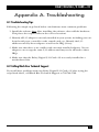
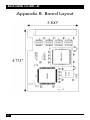
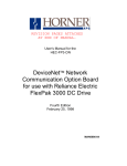
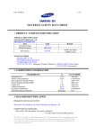
DECEMBER 1999
IC903C
Relay/Digital I/O Card—32
CUSTOMER
SUPPORT
INFORMATION
Order toll-free in the U.S.: Call 877-877-BBOX (outside U.S. call 724-746-5500)
FREE technical support 24 hours a day, 7 days a week: Call 724-746-5500 or fax 724-746-0746
Mailing address: Black Box Corporation, 1000 Park Drive, Lawrence, PA 15055-1018
Web site: www.blackbox.com • E-mail: [email protected]
RELAY/DIGITAL I/O CARD—32
FEDERAL COMMUNICATIONS COMMISSION
AND
INDUSTRY CANADA
RADIO FREQUENCY INTERFERENCE STATEMENTS
This equipment generates, uses, and can radiate radio-frequency energy, and if not
installed and used properly, that is, in strict accordance with the manufacturer’s
instructions, may cause interference to radio communication. It has been tested
and found to comply with the limits for a Class A computing device in accordance
with the specifications in Subpart B of Part 15 of FCC rules, which are designed to
provide reasonable protection against such interference when the equipment is
operated in a commercial environment. Operation of this equipment in a
residential area is likely to cause interference, in which case the user at his own
expense will be required to take whatever measures may be necessary to correct
the interference.
Changes or modifications not expressly approved by the party responsible
for compliance could void the user’s authority to operate the equipment.
This digital apparatus does not exceed the Class A limits for radio noise emission from
digital apparatus set out in the Radio Interference Regulation of Industry Canada.
Le présent appareil numérique n’émet pas de bruits radioélectriques dépassant les limites
applicables aux appareils numériques de la classe A prescrites dans le Règlement sur le
brouillage radioélectrique publié par Industrie Canada.
This product fulfills the requirements of EMC directive (89/336/EEC) and of the
low-voltage directive (73/23/EEC) issued by the European Commission. The
following European standards must be met:
• EN55022 Class A—“Limits and methods of measurement of radio interference
characteristics of information technology equipment”
• EN50082-1—“Electromagnetic compatibility—Generic immunity standard”
Part 1: Residential, commercial, and light industry
• EN60950 (IEC950)—“Safety of information technology equipment, including
electrical business equipment”
1
RELAY/DIGITAL I/O CARD—32
NORMAS OFICIALES MEXICANAS (NOM)
ELECTRICAL SAFETY STATEMENT
INSTRUCCIONES DE SEGURIDAD
1. Todas las instrucciones de seguridad y operación deberán ser leídas antes de
que el aparato eléctrico sea operado.
2. Las instrucciones de seguridad y operación deberán ser guardadas para
referencia futura.
3. Todas las advertencias en el aparato eléctrico y en sus instrucciones de
operación deben ser respetadas.
4. Todas las instrucciones de operación y uso deben ser seguidas.
5. El aparato eléctrico no deberá ser usado cerca del agua—por ejemplo, cerca
de la tina de baño, lavabo, sótano mojado o cerca de una alberca, etc..
6. El aparato eléctrico debe ser usado únicamente con carritos o pedestales que
sean recomendados por el fabricante.
7. El aparato eléctrico debe ser montado a la pared o al techo sólo como sea
recomendado por el fabricante.
8. Servicio—El usuario no debe intentar dar servicio al equipo eléctrico más allá
a lo descrito en las instrucciones de operación. Todo otro servicio deberá ser
referido a personal de servicio calificado.
9. El aparato eléctrico debe ser situado de tal manera que su posición no
interfiera su uso. La colocación del aparato eléctrico sobre una cama, sofá,
alfombra o superficie similar puede bloquea la ventilación, no se debe colocar
en libreros o gabinetes que impidan el flujo de aire por los orificios de
ventilación.
10. El equipo eléctrico deber ser situado fuera del alcance de fuentes de calor
como radiadores, registros de calor, estufas u otros aparatos (incluyendo
amplificadores) que producen calor.
11. El aparato eléctrico deberá ser connectado a una fuente de poder sólo del
tipo descrito en el instructivo de operación, o como se indique en el aparato.
2
RELAY/DIGITAL I/O CARD—32
12. Precaución debe ser tomada de tal manera que la tierra fisica y la polarización
del equipo no sea eliminada.
13. Los cables de la fuente de poder deben ser guiados de tal manera que no
sean pisados ni pellizcados por objetos colocados sobre o contra ellos,
poniendo particular atención a los contactos y receptáculos donde salen del
aparato.
14. El equipo eléctrico debe ser limpiado únicamente de acuerdo a las
recomendaciones del fabricante.
15. En caso de existir, una antena externa deberá ser localizada lejos de las lineas
de energia.
16. El cable de corriente deberá ser desconectado del cuando el equipo no sea
usado por un largo periodo de tiempo.
17. Cuidado debe ser tomado de tal manera que objectos liquidos no sean
derramados sobre la cubierta u orificios de ventilación.
18. Servicio por personal calificado deberá ser provisto cuando:
A: El cable de poder o el contacto ha sido dañado; u
B: Objectos han caído o líquido ha sido derramado dentro del aparato; o
C: El aparato ha sido expuesto a la lluvia; o
D: El aparato parece no operar normalmente o muestra un cambio en su
desempeño; o
E: El aparato ha sido tirado o su cubierta ha sido dañada.
3
RELAY/DIGITAL I/O CARD—32
TRADEMARKS USED IN THIS MANUAL
Any trademarks mentioned in this manual are acknowledged to be the property of the
trademark owners.
4
RELAY/DIGITAL I/O CARD—32
Contents
Chapter
Page
1. Specifications. . . . . . . . . . . . . . . . . . . . . . . . . . . . . . . . . . . . . . . . . . . . . . . . . . . . . . 6
2. Introduction . . . . . . . . . . . . . . . . . . . . . . . . . . . . . . . . . . . . . . . . . . . . . . . . . . . . . . 7
2.1 Overview. . . . . . . . . . . . . . . . . . . . . . . . . . . . . . . . . . . . . . . . . . . . . . . . . . . . . . . 7
2.2 What the Package Includes. . . . . . . . . . . . . . . . . . . . . . . . . . . . . . . . . . . . . . . . 7
2.3 Features . . . . . . . . . . . . . . . . . . . . . . . . . . . . . . . . . . . . . . . . . . . . . . . . . . . . . . . 7
2.4 Software . . . . . . . . . . . . . . . . . . . . . . . . . . . . . . . . . . . . . . . . . . . . . . . . . . . . . . . 7
3. Installation. . . . . . . . . . . . . . . . . . . . . . . . . . . . . . . . . . . . . . . . . . . . . . . . . . . . . . . . 8
3.1 Card Setup . . . . . . . . . . . . . . . . . . . . . . . . . . . . . . . . . . . . . . . . . . . . . . . . . . . . . 8
3.2 Operating-System Installation . . . . . . . . . . . . . . . . . . . . . . . . . . . . . . . . . . . . . 8
3.3 System Installation. . . . . . . . . . . . . . . . . . . . . . . . . . . . . . . . . . . . . . . . . . . . . . . 8
3.4 Register Description . . . . . . . . . . . . . . . . . . . . . . . . . . . . . . . . . . . . . . . . . . . . . 9
3.5 I/O Connector Pinout (DB37 male). . . . . . . . . . . . . . . . . . . . . . . . . . . . . . . . 10
Appendix A. Troubleshooting . . . . . . . . . . . . . . . . . . . . . . . . . . . . . . . . . . . . . . . . . . 11
A.1 Troubleshooting Tips. . . . . . . . . . . . . . . . . . . . . . . . . . . . . . . . . . . . . . . . . . . . 11
A.2 Calling Black Box Technical Support . . . . . . . . . . . . . . . . . . . . . . . . . . . . . . . 11
Appendix B. Board Layout. . . . . . . . . . . . . . . . . . . . . . . . . . . . . . . . . . . . . . . . . . . . . 12
5
RELAY/DIGITAL I/O CARD—32
1. Specifications
Mean Time Between Failures (MTBF)—> 150,000 hours
Maximum Temperature Tolerance—Operating: 32 to 122°F (0 to 50°C); Storage: -4
to +158°F (-20 to +70°C)
Humidity—10 to 90% noncondensing
Power—Supply line: +5 VDC; Rating: 500 mA
Size—Including goldfingers: 3.3"H x 4.7" L (8.4 x 11.9 cm); Excluding
goldfingers: 3"H x 4.7"L (7.6 x 11.9 cm)
Weight—3.2 oz. (90.7 g)
6
RELAY/DIGITAL I/O CARD—32
2. Introduction
2.1 Overview
The Relay/Digital I/O Card—32 provides PC-based control and automation of
equipment, such as sensors, switches, satellite systems, and other industrial
automation systems. The Card gives the PC four 8-bit ports. The status of each of
the four ports is user-selectable as input or output by simply writing a control word
to the port register. You can customize the combination of inputs and outputs as
needed.
2.2 What the Package Includes
The Card ships with the following items:
• Relay/Digital I/O Card—32
• DIO Software
• This users’ manual
If anything is missing or damaged, please call Black Box at 724-746-5500.
2.3 Features
• 32 channels (four ports of eight channels each) of digital I/O configurable as
inputs or outputs
• Terminal block and cable kit available to simplify field wiring requirements
• Supports all PCI interrupts
2.4 Software
The Card comes with Windows 95, 98, and Windows NT drivers, with a consistent
and straightforward application program interface (API). This DIO software
supports popular development environments, including Visual C++, Visual Basic,
and Delphi. It also includes a utility for configuring the driver parameters under
Windows 95, 98, and Windows NT.
The Relay/Digital I/O Card—32 also supports DOS, QNX, and Linux.
7
RELAY/DIGITAL I/O CARD—32
3. Installation
3.1 Card Setup
The Relay/Digital I/O Card—32 is a fully compliant plug-and-play adapter. All
card resources (I/O address, IRQ selection) are auto-assigned by either your
system BIOS or your plug-and-play operating system.
3.2 Operating-System Installation
Please install the proper software for your adapter before installing the hardware.
Refer to the supplied software for the correct operating-system installation
procedure.
3.3 System Installation
You can install the Card in any of the PCI expansion slots. Follow these steps:
1. Turn off the power to the PC. Disconnect the power cord.
2. Remove the PC case cover.
3. Locate an available PC slot and remove the blank slot cover.
4. Gently insert the Card into the slot. Make sure that the Card is seated
properly.
5. Replace the screw.
6. Replace the cover.
7. Connect the power cord. Installation is complete.
8
RELAY/DIGITAL I/O CARD—32
3.4 Register Descriptions
Address Mode
D7
D6
D5
D4
D3
D2
D1
Base+0 RD/WR
PAD7
PAD6
PAD5
PAD4
PAD3
PAD2
PAD1
PAD0
D0
Base+1 RD/WR
PBD7
PBD6
PBD5
PBD4
PBD3
PBD2
PBD1
PBD0
Base+2 RD/WR
PCD7
PCD6
PCD5
PCD4
PCD3
PCD2
PCD1
PCD0
Base+3 RD/WR
PDD7
PDD6
PDD5
PDD4
PDD3
PDD2
PDD1
PDD0
Base+4 RD/WR
{0}
{0}
{0}
{0}
DIRD
DIRC
DIRB
DIRA
Base+5 RD/WR
IRQEN
IRQST
{0}
{0}
{0}
{0}
IRC1
IRC0
Base+6 RD Only {0}
{0}
{0}
{0}
{0}
{0}
{0}
{0}
Base+7 RD Only {0}
{0}
{0}
{0}
{0}
{0}
{0}
{0}
NOTE
All ports are set to input after reset or power up. Interrupt source is
Base+0 bit D0. When selecting the Interrupt mode, always disable
interrupts before changing or setting states. This will help prevent
inadvertent or unexpected interrupts. When using the high and low level
interrupts, a change in state of the input must occur before the interrupt
can be cleared. The device providing the input to Base+0, bit D0, must
do this.
PAD0-7=Port A (Base+0)
PBD0-7=Port B (Base+1)
PCD0-7=Port C (Base+2)
PDD0-7=Port D (Base+3)
DIRA-D=Port A-D direction control (Base+4)
0=input
1=output
IRC0-1=Interrupt Mode select (Base+5)
IRC1
IRC0
0
0
Low level
0
1
High level
1
0
Falling edge
1
1
Rising edge
IRQEN=enable interrupts (Base+5)
0=disabled
1=enabled (disabled after reset or power up)
IRQST=interrupt status (Base+5)
1=interrupt pending (reading the bit clears interrupt)
9
Relay/Digital/IO Card-32
50 pin ribbon cable pin out
Description
Pin #
Port A
A0
A1
A2
A3
A4
A5
A6
A7
47
45
43
41
39
37
35
33
Port B
B0
B1
B2
B3
B4
B5
B6
B7
GND
+5V
10
31
29
27
25
23
21
19
17
Description
Pin #
Port C
C0
15
C1
13
C2
11
C3
9
C4
7
C5
5
C6
3
C7
1
Port D
D0
2
D1
4
D2
6
D3
8
D4
10
D5
12
D6
14
D7
16
All Even pins from 18
49
RELAY/DIGITAL I/O CARD—32
Appendix A. Troubleshooting
A.1 Troubleshooting Tips
Following the simple steps listed below can eliminate most common problems.
1. Install the software first. After installing the software, then add the hardware.
This places the required files in the correct locations.
2. Identify all I/O adapters currently installed in your system, including your onboard serial ports, controller cards, sound cards, etc. Identify the I/O
addresses used by these adapters as well as the IRQ (if any).
3. Make sure that there is no confilct with currently installed adapters. No two
adapters can occupy the same I/O address and may not be allowed to share
IRQs.
4. Make sure that the Relay/Digital I/O Card—32 is securely installed in a
motherboard slot.
A.2 Calling Black Box Technical Support
If you still have problems with your Relay/Digital I/O Card—32 after trying the
steps listed above, call Black Box Technical Support at 724-746-5500.
11
RELAY/DIGITAL I/O CARD—32
Appendix B. Board Layout
12
© Copyright 1999. Black Box Corporation. All rights reserved.
1000 Park Drive
•
Lawrence, PA 15055-1018
•
724-746-5500
•
Fax 724-746-0746