1
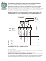
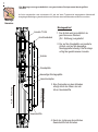
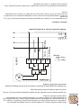
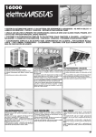
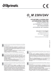
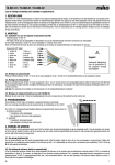
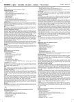
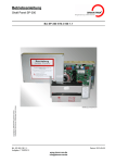
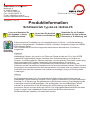
1
SIMON RWA Systeme GmbH
Medienstr. 8
D- 94036 Passau
Tel. +49 851 98870-0
Fax: +49 851 98870-70
E-mail: [email protected]
Internet: http://www.simon-rwa.de
Ausgabe: C - 01/11
Produktinformation
Schlitzantrieb Typ EA-LS-1000/48-PS
Lesen und beachten Sie
die Angaben in dieser
Produktinformation!
Systembeschreibung
Vermeiden Sie dadurch
Schäden und Gefahren!
Bewahren Sie die Produktinformation für den späteren
Gebrauch (z. B. Wartung) auf!
Elektromotorische Fernbedienung von Lamellenfenstern zur Rauch - und Wärmeableitung,
sowie zu Lüftungszwecken. Einsetzbar mit RWA - und/oder Lüftungssteuerungen der SIMON
RWA Systeme GmbH.
Der Schlitzantrieb ist mit einem integrierten elektronischen Klemmschutz (ProSense®)
ausgerüstet.
Allgemein:
Kraftbetätigte Fenster, die (auch nur mit Teilen des Fensters) tiefer als 2,5 m über OKFFB
(Oberkante Fertigfussboden) liegen, bedürfen einer Risikoeinschätzung im Hinblick auf
Quetsch- und Klemmgefahren. Mehrere nationale und internationale Vorschriften regeln die je
nach Nutzungsart des Fensters notwendigen Schutzmassnahmen. Es wird eine
Risikoeinschätzung durchgeführt. Entsprechend der Einbausituation, der Nutzung des
Gebäudes und der verwendeten Steuertechnik wird eine Schutzklasse definiert. Diese ist dann
Grundlage für die entsprechenden Schutzmassnahmen. Wir bieten Ihnen mit unserem System
ProSense® eine technisch optimierte und qualitativ hochwertige Lösung zur Erfüllung dieser
Forderungen.
Haftung:
Der Bauplaner/Architekt, bzw. die ausschreibende Stelle müssen die Anforderungen an
kraftbetätigte Fenster eindeutig vorgeben. Hierzu gehört die Abstimmung mit den zuständigen
Behörden (z. B. Bauamt) ggf. bei gewerblicher und öffentlicher Nutzung unter Beteiligung des
zuständigen Unfallversicherungsträgers. Der Auftraggeber, der das kraftbetätigte Fenster
errichtet, ist verantwortlich für die Einhaltung der Ausschreibung unter Beachtung der
technischen Regeln und dem Stand der Technik. Der Auftraggeber/Betreiber/Nutzer hat dafür
Sorge zu tragen, dass kraftbetätigte Fenster gemäß der Benutzerinformationen/
Betriebsanleitungen betrieben und unterhalten werden.
2
Wissenswertes:
Bei ProSense® handelt es sich um eine elektronische Eingriffsicherung für kraftbetätigte Fenster
an den Hauptschließkanten. Das System ProSense® ist eine spezielle Elektronik zum
Klemmschutz für 24 V DC Antriebe und ist direkt im Antrieb verbaut. Der Einsatz dieser
Systembe- Technik setzt eine Testreihe und kundenspezifische Parametrierung der Software an einem
schreibung Originalmuster im Werk Passau voraus. Um den optimalen Klemmschutz gewährleisten zu
können, erfolgt die Fertigung der Antriebe in Abstimmung mit den technischen Anforderungen,
resultierend aus den vorangegangenen Tests.
Funktionsweise ProSense®:
Durch eine intelligente Elektronik “lernt” der Antrieb innerhalb von 5 Lernfahrten am jeweiligen
Fenster (diese müssen zwingend bei der Installation durchgeführt werden) wie groß der
Kraftbedarf ist (über Strommessung des Antriebs) und regelt diesen für den kompletten
Öffnungsweg auf ein Optimum. Im Bereich des Klemmschutzes wird diese definierte Kraft
ständig mit der IST-Kraft verglichen. Wenn nun eine ungewöhnliche Abweichung festgestellt
wird, z. B. durch ein eingeklemmtes Körperteil, reagiert die Elektronik. Diese öffnet das
Fenster einige Zentimeter und schaltet den Motor ab. Die Kraftabweichung ist durch einen
Parameter fest definiert. Der Antrieb kann nun nur noch in Richtung AUF bewegt werden. Der
überwachte Einklemmbereich erstreckt sich von der Hauptschließkante bis etwa 200 mm des
geöffneten Fensters. Die ProSense®-Funktion ist beim Anfahren des Antriebes ausgeschaltet
und wird erst nach der Startphase wieder eingeschaltet. Wurde der Einklemmschutz aktiviert,
wird die Schließkraft beim nächsten Schließvorgang erhöht. Um dieselbe Sensibilität wie vor
dem Einklemmen zu erreichen sind ca. 5 störungsfreie Fahrzyklen in ZU-Richtung nötig bis der
Antrieb in Endlage ZU selbsttätig abschaltet. Um ein Dichtschließen des Fensters
gewährleisten zu können, wird die Funktion ProSense® einige mm vor dem komplett
geschlossenen Fenster ausgeschaltet. Der Antrieb zieht das Fenster somit sicher in seine
Dichtung. In Richtung AUF ist diese Funktion ausgeschaltet. Das System “lernt” über seinen
gesamten Lebenszyklus ca. 11 000 Zyklen den Kraftbedarf des Fensters, das bedeutet eine
Verschlechterung oder Verbesserung der Mechanik des Fensters wird ausgeglichen. Die
Kraftabweichung bleibt aber unverändert und somit bleibt auch die Sensibilität erhalten.
Achtung!
Der Einbau von technischen Einrichtungen wie Pro Sense® dienen dem Schutz der Personen,
die mit dem kraftbetätigten Fenster in Verbindung kommen. Er kann aber nicht organisatorische
Maßnahmen kompensieren, die ergriffen werden müssen um einen optimalen Klemmschutz zu
erreichen. Insbesondere befreit der Einbau technischer Hilfsmittel den Planer und Errichter
nicht von der Notwendigkeit einer Risikobeurteilung und der Ergreifung der sich daraus
ergebenden notwendigen Maßnahmen.
Die Klemmschutzelektronik wird nur in ZU-Richtung aktiviert.
Damit der Einklemmschutz zuverlässig funktioniert, müssen nach der Erstinstallation zwingend
5 vollständige Fahrzyklen absolviert werden. Der Antrieb muss jeweils in den Endlagen
selbsttätig abschalten. Danach ist der Einklemmschutz optimal eingestellt und betriebsbereit!
3
F-Kontaktfunktion:
Für AUF- und ZU-Richtung:
Systembe- Wird der Schlitzantrieb durch Überlast oder bei Erreichen des elektronischen Hubs in der
schreibung Fahrtrichtung AUF, bzw. Fahrtrichtung ZU abgeschaltet, wird der F-Kontakt wie bei
“Technische Daten” und “Elektrischer Anschluss” beschrieben ausgegeben.
1.) Typ. / Version:
EA-LS-1000/48-PS
2.) Bemessungsspannung [V DC]:
+24 V; +20 %; -10 %
Technische 3.) Restwelligkeit [Vss]:
Daten
Allgemein 4.) Bemessungsstrom [A]:
< 500 mV
1,1 A
5.) Abschaltstrom [A]:
max. 1,1 A
6.) Maximalstrom [A]:
ca. 2,8 A
7.) Einschaltdauer [%]:
ED 30; bezogen auf 10 min.
8.) Nennhubgeschwindigkeit [mm/s]:
4,3 mm/s
9.) Leerlaufhubgeschwindigkeit [mm/s]:
5,2 mm/s
10.) Hubgeschwindigkeit 2/3 Last [mm/s]:
4,7 mm/s
11.) Hubtoleranz [%]:
+/- 5 %
12.) Nennschubkraft [N]:
1000 N
13.) Max. Schubkraft [N]:
1000 N
14.) Max. Zugkraft [N]:
1000 N
15.) Hublängen lieferbar [mm]:
48 mm
16.) Schutzart [IP]:
IP 20
17.) Lebensdauer [Zyklen] Öffnungs- und Schließzyklen:
18.) Umgebungstemperaturbereich [°C]:
19.) Temperaturstandsicherheit:
10 000 Lüftung + 1000 RWA
-5° C bis +75° C
Temperatursicherheit 30 min. / 300°C
4
20.) Material Schubrohr:
Aluminium, EV1
21.) Material Antriebsgehäuse:
Aluminium, EV1
Technische 22.) Einbaumass Motor (B x H); [mm]:
Daten
Allgemein 23.) Anschlussleitung [m]:
400 mm x 36 mm x 46 mm
2 000 mm ;
5-polig; 0,75 mm2;
Silicon SIR/SIR-SO-EWKF lichtgrau
24.) Umpolzeit zwischen "S", "O" [ms]:
> 500 ms
25.) Schallpegel [dB] im Abstand von 1 m:
26.) F-Kontakt ( "S" Weiterleitung)
Bemessungsspannung [V DC]:
Kontaktbelastung Relais [V DC]; [A]:
< 70 dB
24 V; +20 %; -10 %
max. 30 V; max. 2 A
Zu 6.) Der Maximalstrom des Schlitzantriebes wird im Einklemmfall beim
Reversiervorgang nicht begrenzt
Zu 15.) Hub begrenzbar
Zu 20.), 21.) Aluminium eloxiert (farblos)
Zu 26.) Beim F-Kontakt wird immer das Potential der Klemme „S“ ausgegeben, d.h.
wenn „S“ Minus führt wird Minus weitergeleitet und
wenn “S“ Plus führt wird Plus weitergeleitet
Bitte berücksichtigen Sie vor der Montage folgende wichtige Informationen!
Der Antrieb ist mit einer mikroprozessorgesteuerten Abschaltung ausgestattet
und bietet Ihnen weitere Sonderfunktionen an. Bei dem vorliegenden Fertigungsstand
können Sie serienmäßig folgende Sonderfunktionen verwenden:
Wichtige
Information Elektronische Endlagenerkennung: Wenn der Antrieb in seine Endlage ZU gefahren ist
und von der Versorgung getrennt wird, bewirkt ein erneutes Ansteuern in die Richtung ZU
keinen neuen Motoranlauf. In diesem Fall muss der Antrieb erst in Richtung AUF
angesteuert werden um wieder aus seiner Endlage herauszufahren. In Richtung AUF gilt
diese Funktion sinngemäß ebenso. Dies bietet einen größtmöglichen Schutz vor
Getriebeschäden durch Fremdansteuerung
(z. B. GLT, LON).
Wichtig: Zu beachten sind die VDE 0833 für Gefahrenmeldeanlagen, VDE 0100 für
elektrische Anlagen, DIN 18232 (EN 12101-2) für RWA - Anlagen, die Bestimmung der
örtlichen Feuerwehr und des EVU für den Netzanschluss, sowie BGV A3 und BG Regel
BGR 232.
Gefahrenhinweise
Bitte beachten: Kraftbetätigte Fenster dürfen nicht im Griffbereich liegen.
Quetschgefahr! Es sind die Vorschriften (BGR 232) des Hauptverbandes der
gewerblichen Berufsgenossenschaften zu berücksichtigen.
5
Die Montage muss grundsätzlich von geschultem Fachpersonal durchgeführt werden.
Erst nach Überprüfung der gesamten Anlage, an die 24 V Versorgung anschließen.
Der Antrieb ist mit einem elektronischen Überlastschutz ausgestattet.
Achtung: Der Antrieb darf nur mit 24 V Schutzkleinspannung betrieben werden!
Die Energieversorgung muss für den Antrieb ausgelegt sein. Höhe und Qualität der
Spannung und Stromstärke müssen mit den Angaben auf dem Typenschild übereinstimmen.
Vor der ersten Inbetriebnahme ist die Zuleitungsverkabelung zu kontrollieren. Dabei ist
insbesondere der Aderquerschnitt zu berücksichtigen.
Aderquerschnitt: [mm2 ] = 0,019 x Motorenzahl x Stromaufnahme pro Motor [A] x
Leitungslänge [m] (bei Trafo - Primärspannung von 230 V und Temperatur 25° C)
1. Antrieb
M
24 V DC
O
AM-874
F
Braun
S
Blau
C
Rot (max. +5V DC)
P
Gelb (0 V)
AUF: S = +
O=ZU: umpolen
Schwarz
MC
24V DC
Elektrischer
Anschluss
+ (-)
- (+)
Parallelbetrieb von max. 4 Antrieben möglich
Achtung ProSense®:
Die interne Steuerelektronik gibt nach dem Abschalten des Antriebes jeweils das Potenzial
von (S) auf den Rückkontakt (F).
Potenzialfortschaltung (z.B. Rückmeldung) über “F”-Kontakt (Schwarz).
Die Adern (C und P) dürfen nicht verbunden werden und müssen elektrisch isoliert werden.
(Schwarz) muss je nach Anwendung elektrisch isoliert werden!
Auf eine dauerhafte und mindestens für die auf dem Typenschild angegebene Motorkraft
ausgelegte Befestigung des Antriebes am Fenster - bzw. Flügelrahmen ist zu achten.
6
Für die nachfolgend beschriebene Inbetriebnahme ist das Resetgerät mit der
Artikelnummer M2 3400 aus dem SIMON RWA Systemprogramm notwendig. Das
Resetgerät erhalten Sie bei unseren Vertriebspartnern oder direkt beim Hersteller.
Montage/
Inbetriebnahme
1. Den Antrieb elektrisch anschließen lt . Produktbeschreibung (Schaltbild).
1.1
1.2
1.3
1.4
1.5
1.6
1.7
1.8
1.9
1.10
1.11
1.12
1.13
1.14
1.15
1.16
1.17
1.18
1.19
1.20
1.21
1.22
1.23
Den Antrieb stoppen (S und O spannungsfrei setzen).
Die Grundstellung des RESET Geräts ProSense® prüfen > EIN/AUS in AUS;
RESET/TEST auf TEST
Die rote Ader des Antriebskabels an die rote Buchse des RESET Gerätes
anschließen.
Die gelbe Ader des Antriebskabels an die gelbe
Buchse des RESET Gerätes anschließen.
Schalter EIN/AUS in EIN schalten > In dieser Schalterposition besteht die
Möglichkeit die COM Spannung zu messen.
Schalter RESET/TEST auf RESET schalten > In der Anzeige muss ein
Spannungswert von 4,65 V DC +/- 0,05 V DC angezeigt werden,
bei Abweichung ist die Batteriespannung zu prüfen oder
das Gerät zur Kalibrierung ins Werk einsenden.
Den Antrieb in AUF-Richtung ansteuern - der Antrieb muss in
ZU-Richtung fahren und befindet sich somit im Resetmodus.
Der Antrieb muss solange angesteuert werden, bis er selbstständig abschaltet.
Den Antrieb stoppen (S und O spannungsfrei setzen).
Schalter RESET/TEST auf TEST schalten.
Schalter EIN/AUS auf AUS schalten.
Der Nullabgleich ist abgeschlossen.
COM Spannung über Hub kontrollieren > Schalter RESET/TEST auf TEST
schalten.
Schalter EIN/AUS auf EIN schalten.
Antrieb in ZU ansteuern.
Anzeige muss einen Spannungswert zwischen 0,47 V DC bis 0,50 V DC
ausgeben.
Antrieb unter Beachtung der Umpolzeit von > 500 ms in AUF ansteuern.
Spannungswert der Anzeige steigt bis 100 % Hub auf 4,45 V DC +/- 0,15 V DC
Antrieb unter Beachtung der Umpolzeit von > 500 ms in ZU ansteuern.
Spannungswert der Anzeige sinkt bis Grundstellung.
Nach Abschaltung des Antriebs muss die Anzeige einen Spannungswert
zwischen 0,47 V DC bis 0,50 V DC ausgeben.
Schalter EIN/AUS auf AUS schalten.
Anschlusskabel gelb/rot abklemmen und isolieren.
2. Den Antrieb mindestens 5 Zyklen in AUF und ZU-Richtung ansteuern
(Lernphase). In der Lernphase muss der Antrieb immer bis in die Endlage gefahren
sein und solange angesteuert werden bis er selbsttätig abschaltet.
Die Klemmschutzelektronik wird nur in ZU-Richtung aktiviert.
Hinweis:
Kommt es durch äußere Umstände zu einer Verstellung der Position des Antriebes, muss ein
Reset durchgeführt werden. Bei dieser Resetfahrt wird der Nullpunkt des Fensters neu
eingestellt und der gelernte Kraftbedarf des Fensters wird auf die Maximalwerte
(Auslieferungszustand) zurückgesetzt.
Reset wie unter Punkt 1 durchführen.
7
Die Montage muss grundsätzlich von geschultem Fachpersonal durchgeführt
werden!
Auf eine dauerhafte und mindestens für die auf dem Typenschild angegebene Motorkraft
ausgelegte Befestigung des Antriebes am Rahmen des Lamellenelementes ist zu achten.
Montagehinweise
Montageablauf
Lamelle TG 24
Anschlusskabel
1. Der Antrieb wird grundsätzlich im
geschlossenen Zustand
(ZU - Richtung) ausgeliefert.
2. Der auf die Grundplatte vormontierte
Antrieb, wird auf die bauseitige
Montageplatte befestigt. Die Montage
erfolgt bei geschlossener Lamelle.
Antrieb
Grundplatte
bauseitige Montageplatte
Positionierung
des Antriebes
AUF - Richtung
Lamellenzapfen
3. Eine Feinjustierung des Antriebes
erfolgt durch das Lösen der seitlichen Gewindestifte.
Gewindestifte
4. Nach der Justierung die seitlichen
Gewindestifte fest anziehen.
8
EG-Herstellererklärung
Hiermit erklären wir die Konformität des Produktes mit den dafür geltenden Richtlinien. Die
Konformitätserklärung kann in der Firma eingesehen werden und wird Ihnen auf Anforderung zugesandt.
Bei einer nicht mit uns abgestimmten Änderung verliert diese Erklärung ihre Gültigkeit.
Firmenanschriften
Deutschland:
Simon RWA® Systeme GmbH
Medienstr. 8
D - 94036 Passau
Tel.: +49 (0)851 98870 - 0
Fax: +49 (0)851 98870-70
E-Mail: [email protected]
Internet: www.simon-rwa.de
Schweiz:
Österreich:
Simon RWA® Systeme AG
Allmendstrasse 8
CH - 8320 Fehraltorf
Tel.: +41 (0)44 956 50 30
Fax: +41 (0)44 956 50 40
E-Mail: [email protected]
Internet: www.simon-rwa.ch
Simon RWA® Systeme GmbH
Aumühlweg 21 Top 313/314
A - 2544 Leobersdorf
Tel.: +43 (0)2256 64001
Fax: +43 (0)2256 64070
E-Mail: [email protected]
Internet: www.simon-rwa.at
8
EC-Manufacturer’s declaration
We herewith declare the conformity of the product with the applicable directives. The declaration of
conformity can be viewed at the company and is mailed to you upon request. This declaration is rendered
invalid with any changes not agreed to by us.
Company addresses
Germany:
Simon RWA® Systeme GmbH
Medienstr. 8
D - 94036 Passau
Tel.: +49 (0)851 98870 - 0
Fax: +49 (0)851 98870-70
E-Mail: [email protected]
Internet: www.simon-rwa.de
Austria:
Simon RWA® Systeme GmbH
Aumühlweg 21 Top 313/314
A - 2544 Leobersdorf
Tel.: +43 (0)2256 64001
Fax: +43 (0)2256 64070
E-Mail: [email protected]
Internet: www.simon-rwa.at
Switzerland:
Simon RWA® Systeme AG
Allmendstrasse 8
CH - 8320 Fehraltorf
Tel.: +41 (0)44 956 50 30
Fax: +41 (0)44 956 50 40
E-Mail: [email protected]
Internet: www.simon-rwa.ch
7
The installation may only be accomplished by technical specialists.
Please see that the fastening of the actuator on the louvre window is durable and dimensioned
at least for the actuators force mentioned on the type label.
Installation
options
Mounting process
glass louvre TG 24
connecting cable
actuator
1. Basically the acuator is delivered
in closed state.
(CLOSE -Alignment)
2. Being pre-installed to the bottom
plate the actuator is fastened to the
mounting plate (provided by the
building contractor).
The glass louvre is closed during
assembly.
bottom plate
mounting plate by the building contractor
glass louvre pivot
OPEN - Alignment
positioning of the
actuator
threaded pins
3. The detachment of the lateral
threaded pins causes a precise
adjustment of the actuator.
Attention: The actuator has to be
positioned according to the
arrow’s route and has to be
regulated in that way that the
actuator runs directly into it’s cut
off decrease. The cut off may not
exceed the fixing (end position)
of the glass louvre element!
4. Attach the lateral threaded pins
tightly after the adjustment.
The dimension of power supply has to be suitable for this actuator. Both voltage and
current must agree with the specifications on the “Technical Data General”l. Please check
all cables, especially the cable cross section, before putting it into operation.
Electrical
connection
Cable cross section [mm²] = 0,019 x number of actuators x current of actuator [A] x
cable length [m] (at a transormer-primary voltage of 230 V and temperature 25° C)
6
For the operation described below the RESET device with the part number M2 3400
from SIMON RWA system program is necessary. You will get the RESET device from
our distributors or directly from the manufacturer.
Installation German/English definition: EIN = ON / AUS = OFF / AUF = OPEN / ZU = CLOSE
1. Connect the actuator electrically as described in Additional Information (diagram).
1.1 Stop the actuator (set S and O zero-potential).
1.2 Check the switches of the RESET device. EIN/AUS to AUS and
RESET/TEST to TEST
1.3 Connect the red wire of the power cable to the red jack at the RESET device.
1.4 Connect the yellow wire of the power cable to the yellow jack at the RESET device.
1.5 Switch ON / OFF switch in ON> in this switch position it is possible to measure
the COM voltage.
1.6 Set RESET/TEST switch to RESET > The display must show the voltage value
4,65V DC +/- 0,05 V DC. If not please check the battery voltage or send the
device back to factory for calibration.
1.7 Power the actuator in OPEN-direction, but it has to run in CLOSE direction because
of RESET mode. So you will be sure the RESET mode is set.
1.8 The actuator must be powered until it shuts off automatically.
1.9 Stop the actuator (set S and O zero-potential).
1.10 Switch RESET/TEST to TEST.
1.11 Switch EIN/AUS to AUS.
1.12 The zero adjustment is completed.
1.13 Control COM voltage by the stroke> switch RESET/TEST to TEST
1.14 Switch EIN/AUS to EIN
1.15 Power the actuator in CLOSE direction
1.16 Display has to show a voltage value between 0,47 V DC and 0,50 V DC
1.17 Power the actuator by attention of the pole change time > 500ms in OPEN direction
1.18 The display voltage value has to increase until 100% stroke
to 4,45 V DC +/- 0,15 V DC
1.19 Power the actuator by attention of the pole change time > 500ms
in CLOSE direction
1.20 voltage value of the indicator drops to normal position.
1.21 After switching off the actuator the display has to show a voltage value
between 0.47 V DC to 0.50 V DC.
1.22 Switch EIN/AUS to AUS.
1.23 Disconnect power cable yellow / red and isolate them
2. Run the actuator at least 5 cycles in direction OPEN and CLOSE (Learning phase).
In the learning phase the actuator must always run up to the end position and has
to be controlled until it switches off automatically. The squeeze protection electronics
are activated only in the CLOSE direction.
Attention:
If the position of the actuator is adjusted by external circumstances you have to do a RESET.
With a complete RESET operation the setup point of the window is adjusted new and the
learned force requirements are set back to maximum (delivey status). RESET as explained in
chapter 1.
5
With hoppers outward opening, one shearing action must be additionally applied to the
window drive for limiting tilting motion of the window wing after the actuator in unhinged, e.g.
for cleaning window, so safeguarding the wing against hinging down. This stop position must
be somewhat larger than stroke of the drive. The shearing action must be applied before
beginning with actuator mounting.
Installation
The spindle actuator must be installed with the stepless adjustable bracket set (UK-L or HK-L)
wich is fixed with a clamping collar to the actuator pipe.
The actuator is equipped with an electronic overload cut off and a limit dumping to protect
the actuator and provide durability.
1. Actuator
M
24 V DC
MC
Open: S = +
O=Close: pole
change
24V DC
P
Yellow(0 V)
C
Red (max. +5V DC)
S
Blue
F
O
Brown
Black
AM-874
+ (-)
- (+)
Parallel operation of max. 4 actuators possible
Attention ProSense:
In the end position or by overload the integrated electronics switches potential (S) to (F) (e.g.
for signal).
The red (C ) and yellow (P) cores are only used for resetting the actuator by the reset-device.
Do not connect (C and P). These cores have to be insulated. If F (black) is not used please
insulate.
A durable and is designed for at least the nameplate on the engine mounting strength of the
actuator by the window - or sash to be respected.
4
Aluminium, anodizedEV1
21.) Material housing:
Aluminium, anodized EV1
20.) Material sheare tube:
22.) Motor mounting dimension (B x H); [mm]:
Technical
Data
23.) Connecting cable [m]:
General
24.) Pol change time between "S", "O" [ms]:
25.) Noise level [dB] at a distance of 1 m:
26.) F-Contact ( "S" forwarding)
Rated voltage [V DC]:
Contact load relay [V DC]; [A]:
400 mm x 36 mm x 46 mm
2 000 mm ;
5-pin; 0,75 mm2;
Silicon SIR/SIR-SO-EWKF light grey
> 500 ms
< 70 dB
24 V; +20 %; -10 %
max. 30 V; max. 2 A
App. 6.) The maximum current is not limited in case of squeezing
App. 15.) Stroke can be limited
App. 20.), 21.) Aluminium anodized (colorless)
App. 26.) The F-contact is always the potential of the terminal "S" output, i.e.
if "S" Minus ,then the output is also Minus,
and if "S" Plus then issued Plus
Important: For placing this product on the market outside of Germany the installation and use
has to follow all relevant and valid directives of the respective country!
Attention
Please consider: Force operated windows may not be located within the reaching area of
hands. Bruising danger! The commandments of the association of commercial and industrial
workers’ compensation insurance carriers have to be considered!
The function of the system must be tested periodically by the customer. In case of defect the
installer has to be informed at once. Please change defect parts immediately with original
parts. The system as well as components of a system may just be opened by the
manufacturer.
Material defects:
The device must be used as normally intended. The switch-on duration and the ingress
protection (IP) must be observed, please inquire in case of doubt. The device is subject to
natural wear and tear. In case of material defect claims, these shall be asserted in writing,
stating the source of supply of the device. Prescribed time limits and further provisions with
regard to claims for material defects exclusively correspond with our General Terms and
Maintenance Condition.
This device must be disposed properly at the end of its life time.
Disposal
3
F-Contact function:
For OPEN and direction:
If the slit actuator through overload or when reaching the electronic stroke in the direction
OPEN or CLOSE direction switched off, the F-contact as in "Technical Data General” and
System
Description "Installation" output.
1.) Typ. / Version:
2.) Rated voltage [V DC]:
3.) Ripple [Vss]:
Technical
Data
General
4.) Rated current [A]:
EA-LS-1000/48-PS
+24 V; +20 %; -10 %
< 500 mV
1,1 A
approx. 2,8 A
6.) Maximal current [A]:
max. 1,1 A
5.) Switch of current [A]:
4,7 mm/s
10.) Lifting speed 2/3 weight [mm/s]:
5,2 mm/s
9.) Lifting speed idle [mm/s]:
4,3 mm/s
8.) Nominal speed [mm/s]:
ED 30; at 10 min.
7.) Switch on duration [%]:
48 mm
15.) Stroke [mm]:
1000 N
14.) Max. traction force [N]:
1000 N
13.) Max. shear strength [N]:
1000 N
12.) Nominal shear strength [N]:
+/- 5 %
11.) Lifting speed tolerance [%]:
16.) Protection [IP]:
17.) Lifetime [Cycles] open- and close cycles:
18.) Temperature range [°C]:
19.) Temperature stability:
IP 20
10 000 Ventilation + 1000 SHE
-5° C to +75° C
Security temperature for 30 min. / 300°C
2
Trivia:
ProSense® is an electronic protection at the main closing edge of power operated windows. The
system ProSense® is a special electronics for squeezing protection for 24 V DC actuators and
is installed directly in the actuator. The use of this technique requires a series of tests and
customization of software parameters in an original model in manufacturing in Passau,
System
Description Germany. To ensure the optimal squeezing protection, the production of the actuator is made in
consultation with the technical requirements resulting from the previous tests.
Mode of Operation of ProSense®:
By the use of intelligent electronics the actuator "learns" within five learning cycles at the
specific window (which must necessarily be carried out during installation) how big the power
consumption is (over current measurement of the actuator) and controls it for the complete
stroke as an optimum. In the area of the squeezing protection this known force will be
compared with the current force during the whole closing process. Now if an unusual deviation
is found, for example by a pinched part of the body, the electronics react. This opens the
window a few mm and stops the acuator. The force deviation is defined by a parameter set. The
drive can now be moved only in the direction OPEN. The monitored area of the squeezing
protection extends from the main closing edge to about 200 mm stroke of the open window.
While starting the actuator The ProSense® is turned off and turns on after this starting phase. If
the protection is enabled the force at the next closing will be increased. In order to achieve the
same sensitivity as before about five trouble-free cycles in CLOSE direction are needed for an
automatically power down of the actuator if it is in end position CLOSED.
To ensure as sealing closing of the window, ProSense® switches itself off a few mm before the
window is completely closed. So the actuator moves the window safe in the window’s seal. In
direction OPEN ProSense® is disabled. The system "learns" over its entire life cycle (about 11
000 cycles) the power requirements of the window, which means a deterioration or
improvement of the mechanics of the window is cleared. The force deviation remains
unchanged and thus remains the sensitivity obtained.
Caution!
The installation of technical equipment such as ProSense® protect people who get in contact to
force-operated windows. But it can not compensate for organizational activities wich have to be
taken to achieve an optimal squeezing protection. In particular the installation of technical aids
does not release the planners and builders of the need for risk assessment and execution of
the resulting necessary measures.
The squeezing protection electronics are activated only in CLOSE direction.
For a reliable anti-trap function the system run mandatory five complete cycles after the initial
installation. The actuator must switch off automatically at the end position. Thereafter the
squeezing protection is optimally set and ready!
1
SIMON RWA Systeme GmbH
Medienstr. 8
D- 94036 Passau
Tel. +49 851 98870-0
Fax: +49 851 98870-70
E-mail: [email protected]
Internet: http://www.simon-rwa.de
Edition: B - 07/10
User Manual
slit actuator type EA-LS-1000/48-PS
Please take notice
about the content of
this manual!
To avoid damage and
injury!
Please retain this manual
for later use (manual ...)
It is motorized remote control of louvre windows for smoke and heat ventilation, as well as for
ventilation range. It can be used with SHE - and / or ventilation controls of our system program.
The slit actuator is equipped with an integrated electronic squeeze protection (ProSense®).
System
General:
Describtion
Force-operated windows, which are installed lower (even with parts of the window) than 2.5 m
above finished floor level require a risk assessment with a view to squeezing dangers. Several
national and international regulations govern the necessary protective measures according to
the type of use of the window. The system performs a risk assessment. According to the
installation situation, the use of the building and the used control technique of protection has to
be defined. This is the basis for the appropriate protective measures. With our system
ProSense® we offer you a technically optimized and high quality solution to meet these
demands.
Liability:
The building planners / architect or the tender offering office must purport the requirements for
the force-operated windows. To this issue belongs the trade-off with the competent authorities
(such as construction administration) and if necessary under attendance of competent accident
insurance fund by commercial and public use. The client, who is building the power operated
window, is responsible for compliance with the tender in attention of technical rules and the
state of the art. The client / owner / user is responsible to ensure that power-operated window
are used and maintained according to the user information / manuals.