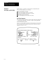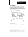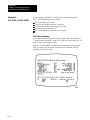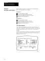
1
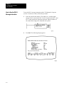
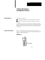
Preface Data Highway/Data Highway Plus Communication Adapter Module (Cat. No. 1785–KA) User’s Manual Preface Important User Information Because of the variety of uses for this equipment and because of the differences between this solid state equipment and electromechanical equipment, the user of and those responsible for applying this equipment must satisfy themselves as to the acceptability of each application and use of the equipment. In no event will Allen-Bradley Company be responsible or liable for indirect or consequential damages resulting from the use or application of this equipment. The illustrations, charts, and layout examples shown in this manual are intended solely to illustrate the text of this manual. Because of the many variables and requirements associated with any particular installation, Allen-Bradley Company cannot assume responsibility or liability for actual use based upon the illustrative uses and applications. No patent liability is assumed by Allen-Bradley Company with respect to use of information, circuits, equipment or software described in this text. Reproduction of the contents of this manual, in whole or in part, without written permission of the Allen-Bradley Company is prohibited. 1988 Allen-Bradley Company. Inc. PLC is a registered trademark of Allen-Bradley Company, Inc. Table of Contents Using This Manual . . . . . . . . . . . . . . . . . . . . . . . . . . . . . . . 3 Chapter Objectives . . . . . . . . . . . . . . . . . . . . . . . . . . . . . . . . . . . Purpose of This Manual . . . . . . . . . . . . . . . . . . . . . . . . . . . . . . . Who Should Read This Manual . . . . . . . . . . . . . . . . . . . . . . . . . . What This Manual Contains . . . . . . . . . . . . . . . . . . . . . . . . . . . . Precautionary Notes . . . . . . . . . . . . . . . . . . . . . . . . . . . . . . . . . . Frequently Used Terms . . . . . . . . . . . . . . . . . . . . . . . . . . . . . . . Related Products . . . . . . . . . . . . . . . . . . . . . . . . . . . . . . . . . . . . Related Publications . . . . . . . . . . . . . . . . . . . . . . . . . . . . . . . . . . In the Next Chapter . . . . . . . . . . . . . . . . . . . . . . . . . . . . . . . . . . 3 3 3 4 5 5 6 7 8 Overview of the 1785KA Module . . . . . . . . . . . . . . . . . . . . 1 Chapter Objectives . . . . . . . . . . . . . . . . . . . . . . . . . . . . . . . . . . . What is the 1785KA Module . . . . . . . . . . . . . . . . . . . . . . . . . . . . What are the Data Highway and Data Highway Plus Networks? . . . Data Highway . . . . . . . . . . . . . . . . . . . . . . . . . . . . . . . . . . . . Data Highway Plus . . . . . . . . . . . . . . . . . . . . . . . . . . . . . . . . . In the Next Chapter . . . . . . . . . . . . . . . . . . . . . . . . . . . . . . . . . . 1 1 2 4 4 4 Installing the 1785KA Module . . . . . . . . . . . . . . . . . . . . . . 1 Chapter Objectives . . . . . . . . . . . . . . . . . . . . . . . . . . . . . . . . . . . Setting the Communication Option Switches . . . . . . . . . . . . . . . . . Switch Assembly SW1: Network Link Communication Rate . . . . Switch Assembly SW2 and SW3: For Future Use . . . . . . . . . . Switch Assemblies SW4, SW5, and SW6: Data Highway and Data Highway Plus Node Addresses . . . . Mounting the 1785KA Module . . . . . . . . . . . . . . . . . . . . . . . . . . Making Connections to the 1785KA Module . . . . . . . . . . . . . . . . . Powering Up the 1785KA Module . . . . . . . . . . . . . . . . . . . . . . . . In the Next Chapter . . . . . . . . . . . . . . . . . . . . . . . . . . . . . . . . . . 1 1 2 3 Communicating Through the 1785KA Module . . . . . . . . . . 1 Chapter Objectives . . . . . . . . . . . . . . . . . . . . . . . . . . . . . . . . . . . Communicating From Data Highway to Data Highway Plus . . . . . . Communicating from a PLC2 on Data Highway to a PLC5 on Data Highway Plus . . . . . . . . . . . . . . . . . . . . . . . . . . . . . . How to Address a PLC5 From a PLC2 . . . . . . . . . . . . . . . . . . Communicating from a PLC3 on Data Highway to a PLC5 on Data Highway Plus . . . . . . . . . . . . . . . . . . . . . . . . . . . . . . Addressing a PLC5 From a PLC3 . . . . . . . . . . . . . . . . . . . . . 1 1 3 6 7 9 9 2 3 5 6 ii Table of Contents Communicating from a Computer on Data Highway to a PLC5 on Data Highway Plus . . . . . . . . . . . . . . . . . . . . . . . . . . . . . . Communicating From Data Highway Plus to Data Highway . . . . . . How to Use the PLC5 Message Instruction . . . . . . . . . . . . . . . . . Monitoring and Modifying the Message Instruction . . . . . . . . . . . . In the Next Chapter . . . . . . . . . . . . . . . . . . . . . . . . . . . . . . . . . . 7 9 10 12 13 1785KA LED Indicators and Diagnostic Counters . . . . . . . 1 Chapter Objectives . . . . . . . . . . . . . . . . . . . . . . . . . . . . . . . . . . . Using the LED Indicators . . . . . . . . . . . . . . . . . . . . . . . . . . . . . . How to Use the 1785KA Diagnostic Counters . . . . . . . . . . . . . . . What is a Diagnostic Counter? . . . . . . . . . . . . . . . . . . . . . . . . How to Read Diagnostic Counters . . . . . . . . . . . . . . . . . . . . . . . . 1785KA Diagnostic Counters . . . . . . . . . . . . . . . . . . . . . . . . . . . Data Highway Diagnostic Counters . . . . . . . . . . . . . . . . . . . . . Data Highway Plus Diagnostic Counters . . . . . . . . . . . . . . . . . . . . In the Following Appendices . . . . . . . . . . . . . . . . . . . . . . . . . . . . 1 1 3 3 4 5 5 6 6 Specifications . . . . . . . . . . . . . . . . . . . . . . . . . . . . . . . . . . 1 Examples of Communicating Between Data Highway and Data Highway Plus . . . . . . . . . . . . . . . . . . . . . . . . 1 Appendix Objectives . . . . . . . . . . . . . . . . . . . . . . . . . . . . . . . . . . Data Highway/Data Highway Plus Example Network Configuration . Example 1: PLC2 (DH) to PLC5 (DH +) . . . . . . . . . . . . . . . . . . . PLC2 Program Example . . . . . . . . . . . . . . . . . . . . . . . . . . . . Example 2: PLC3 (DH) to PLC5 (DH +) . . . . . . . . . . . . . . . . . . . PLC3 Program Example . . . . . . . . . . . . . . . . . . . . . . . . . . . . Example 3: Computer (DH) to PLC5 (DH +) . . . . . . . . . . . . . . . . . PLC2 Normal Unprotected Write . . . . . . . . . . . . . . . . . . . . . . . PLC2 Normal Unprotected Read . . . . . . . . . . . . . . . . . . . . . . PLC3 Normal Unprotected Write (Word Range Write) . . . . . . . . PLC3 Normal Unprotected Read (Word Range Read) . . . . . . . Example 4: PLC5 (DH +) to PLC2 (DH) . . . . . . . . . . . . . . . . . . . PLC2 Write Commands . . . . . . . . . . . . . . . . . . . . . . . . . . . . . PLC2 Read Commands . . . . . . . . . . . . . . . . . . . . . . . . . . . . . Program Verification . . . . . . . . . . . . . . . . . . . . . . . . . . . . . . . . Example 5: PLC5 (DH +) to PLC3 (DH) . . . . . . . . . . . . . . . . . . . PLC3 Write Commands . . . . . . . . . . . . . . . . . . . . . . . . . . . . . PLC3 Read Commands . . . . . . . . . . . . . . . . . . . . . . . . . . . . . Program Verification . . . . . . . . . . . . . . . . . . . . . . . . . . . . . . . . Example 6: PLC5 (DH +) to PLC5 (DH +) . . . . . . . . . . . . . . . . . . PLC3 Read Commands . . . . . . . . . . . . . . . . . . . . . . . . . . . . . PLC5 Write Commands . . . . . . . . . . . . . . . . . . . . . . . . . . . . . Program Verification . . . . . . . . . . . . . . . . . . . . . . . . . . . . . . . . 1 2 3 4 6 7 11 12 13 14 15 16 16 17 17 18 18 19 19 20 20 21 21 Chapter 1 Using This Manual Chapter Objectives After reading this chapter, you should know: if this manual contains the information you need where to locate information in this manual where to locate information on related products Purpose of This Manual This manual describes the 1785-KA PLC-5 Data Highway/Data Highway Plus Communication Adapter Module. It gives you information for: installing the 1785-KA troubleshooting the 1785-KA Who Should Read This Manual You should read this manualbefore attempting to install or use the 1785-KA. We assume that you are already familiar with: Allen-Bradley Programmable Logic Controllers (PLCs) Allen-Bradley Data Highway and Data Highway Plus Chapter 1 Using This Manual What This Manual Contains This manual contains five chapters and two appendices: Chapter/ Appendix: Title: Contains: 1 Using This Manual information you need to know for using this manual properly 2 Overview of the 1785KA conceptual information to help you understand the operation of the 1785KA. Data Highway, and Data Highway Plus Installing the 1785KA Module procedures for: G setting switches G mounting the module G connecting the module to Data Highway Plus G connecting the module to Data Highway G powering up the module 1–4 4 Communicating Through the 1785KA Module guidelines for using your 1785KA to communicate between nodes on your Data Highway Plus and Data Highway networks. 5 1785KA LED Indicators and Diagnostic Counters descriptions of the 1785KA LEDs and diagnostic counters A Specifications 1785KA specifications B Examples of Communicating Between Data Highway and Data Highway Plus examples of how to communicate between Data Highway and Data Highway Plus using the 1785KA Chapter 1 Using This Manual Precautionary Notes In this manual, you will see: warnings that indicate where you may be injured if you do not follow procedures properly cautions that indicate where equipment may be damaged if you do not follow procedures properly important notes that stress information that is critical to your understanding and use of the product Frequently Used Terms In this manual, we use the following terms: This Term: Means: Data Highway Plus formerly the Peer Communications Link (PCL) DH Data Highway DH+ Data Highway Plus node interface point at which devices, such as programmable controllers, connect to the network. Usually, the node is an interface module. except for the PLC5 and T50 terminal which connect directly to Data Highway Plus. In some AllenBradley documentation, you may find the term station used in place of the term node. PLC Programmable Logic Controller; generic term for any of AllenBradley's PLC product lines (such as PLC2, PLC3, etc...) 1–5 Chapter 1 Using This Manual Related Products 1–6 Allen-Bradley offers a wide range of interfaces and software for Data Highway and Data Highway Plus networks, including: Product: Catalog Number: Data Highway Communication Adapter Module 1771KA2 Data Highway Interface Module for PROVOX Instrumentation System 1771KX1 Data Highway Communication Controller Module 1771KE,KF Data Highway PLC4 Communication Interface 1773KAA,KAB Data Highway PLC3 Communication Adapter Module 1775KA PLC3 Family I/O Scanner Communication Adapter Module 1775S5,SR5 Data Highway Plus Communication Adapter Module 1775S5, SR5 Data Highway/Data Highway Plus Communication Interface Module 1770KF2 PLC5 Programming Software 6200PLC5 Industrial Terminal System 1784T50 6001NET Data Highway Communications Software Series 6001 Data Highway Diagnostic Software 6001F3E Chapter 1 Using This Manual Related Publications For more information on DataHighway and Data Highway Plus networks, refer to: Publication: Publication Number: Data Highway Cable Assembly and Installation Manual 17706.2.1 Data Highway/Data Highway Plus Protocol and Command Set Reference Manual 17706.5.16 Data Highway PLC2 (1771KA2) Communication Adapter Module User's Manual 17716.5.1 Data Highway/RS232C (1771KE,KF) Communication Controller Module User's Manual 17716.5.15 Data Highway PLC4 (1773KAA,KAB) Communication Interface User's Manual 17736.5.2 Data Highway PLC3 (1775KA) Communication Adapter Module User's Manual 17756.5.1 PLC3 Family I/O Scanner (1775S5,SR5) Communication Adapter Module 17756.5.5 Data Highway Plus/RS232C (1785KE) Communication Interface Module User's Manual 17856.5.2 Data Highway/Data Highway Plus (1770KF2) Communication Interface Module User's Manual 17706.5.13 3 PLC5 Programming Software User's Manual 6200 6.5.5 Industrial Terminal System (T50) User's Manual 17846.5.1 6001NET (VMS) Data Highway Communication Software User's Manual 60016.5.1 6001NET (RSX11) Data Highway Communication Software User's Manual 60016.5.2 Data Highway Diagnostic Software (6001F3E) User's Manual 60016.5.3 The publications in the previous table are available from Allen-Bradley. Contact your local Allen-Bradley sales office for more information. 1–7 Chapter 1 Using This Manual In the Next Chapter 1–8 In Chapter 2, we give you an overview of how to use the 1785-KA with Data Highway and Data Highway Plus. Chapter 2 Overview of the 1785KA Module Chapter Objectives In this chapter, we give you an overview of the 1785-KA module and how it interfaces with Data Highway and Data Highway Plus networks. What is the 1785KA Module The 1785-KA module is a communication adapter that connects a Data Highway Plus network (including PLC-5 family controllers) to nodes on an Allen-Bradley Data Highway. Figure 2.1 shows the 1785-KA module’s hardware features: diagnostic indicators connector for Data Highway Plus connector for the T50 Industrial Terminal connector for Data Highway Chapter 2 Overview of the 1785-KA Module Figure 2.1 1785KA Communication Interface Module What are the Data Highway and Data Highway Plus Networks? Data Highway and Data Highway Plus are local area networks (LANs) that allow peer-to-peer communication between devices such as: PLCs computers and other intelligent devices Each network consists of a set of cables that provide a channel for communication between various devices. The cables consist of a trunkline that can be up to 10,000 feet long and droplines that can be up to 100 feet each. We refer to the point at which a device interfaces to the cable network as a node. In most cases, the node is an interface module (The PLC-5 has a Data Highway Plus connector built in, so it has no interface module). If you need to add more nodes later, Data Highway and Data Highway Plus networks provide easy reconfiguration and expansion. 2–2 Chapter 2 Overview of the 1785-KA Module The 1785-KA is an active node on both networks. When initiating commands (messages), the module is transparent to nodes on Data Highway, but must be addressed on Data Highway Plus. For more information on using the 1785-KA, refer to Chapter 4. Figure 2.2 shows a 1785-KA connecting a Data Highway Plus network to a Data Highway network. Figure 2.2 The 1785KA in a Typical Data Highway Plus/Data Highway Configuration Important: A computer connected to a Data Highway Plus (through the 1785-KE or 1770-KF2 module) cannot access nodes on a Data Highway through a 1785-KA module. Also, nodes on Data Highway cannot access a computer connected to Data Highway Plus. A 1784-T50 on a Data Highway Plus link cannot program PLCs on another Data Highway Plus link through the 1785-KA. 2–3 Chapter 2 Overview of the 1785-KA Module Data Highway Data Highway connects up to 255 nodes and has a communication rate of 57,600 bits per second. Data Highway implements peer-to-peer communication through a modified token-passing scheme called the floating master. With this arrangement, each node has equal access to become master. The nodes bid for temporary mastership based on their need to send information. Data Highway uses timeouts to recover from a fault that disables the node that has the token. Data Highway Plus Data Highway Plus connects up to 64 nodes and has a communication rate of 57,600 bits per second. You use the Data Highway Plus when you want to connect a small number of nodes (including PLC-5s) on a common link. The Data Highway Plus implements peer-to-peer communication with a token-passing scheme to rotate link mastership among its nodes. Data Highway Plus uses timeouts to recover from a fault that disables the node that has the token. Important: Data Highway Plus optimizes performance for small links. A Data Highway Plus link of 16 nodes offers better performance than a comparable Data Highway link. If you plan on using more than sixteen nodes, however, a Data Highway network probably offers better system performance than a Data Highway Plus link. In the Next Chapter In the next chapter, we give guidelines and procedures for: setting the switches on the 1785-KA mounting the 1785-KA connecting the 1785-KA module to Data Highway Plus connecting the 1785-KA module to Data Highway connecting the T50 terminal to the 1785-KA 2–4 Chapter 3 Installing the 1785KA Module Chapter Objectives This chapter explains how to install the 1785-KA module. There are five parts to installation: setting the communication option switches mounting the module connecting the module to Data Highway Plus connecting the module to Data Highway powering up your module Read the first two chapters of this manual carefully before attempting to install the 1785-KA. Setting the Communication Option Switches The 1785-KA module has 6 switch assemblies (figure 3.1) that enable you to select various communication options. The switch assemblies and their corresponding options are: Select this switch assembly: For this communication option: SW1 SW2, SW3 SW4, SW5, SW6 network link communication rate not used (switches must be set OFF) Data Highway/Data Highway Plus node address Chapter 3 Installing the 1785-KA Module Figure 3.1 Location of the Switch Assemblies on the 1785KA Switch Assembly SW1: Network Link Communication Rate Switch assembly SW-1 lets you select the communication rates for the Data Highway and Data Highway Plus ports on the 1785-KA module. Figure 3.2 shows the switches on SW-1. Figure 3.2 The Switches on Switch Assembly SW1 You must set both switches OFF for SW-1. This setting selects a communication rate of 57,600 bits per second on both Data Highway and the Data Highway Plus. 3–2 Chapter 3 Installing the 1785-KA Module Switch Assembly SW2 and SW3: For Future Use Switch assemblies SW-2 and SW-3 are for future use. You must set both switches on switch assemblies SW-2 and SW-3 to OFF (figure 3.3). Figure 3.3 Setting Switch Assemblies SW2 and SW3 Switch Assemblies SW4, SW5, and SW6: Data Highway and Data Highway Plus Node Addresses You use switch assemblies SW-4, SW-5, and SW-6 to set the node address of the 1785-KA module on both the Data Highway and Data Highway Plus networks. Figure 3.4 shows switch assemblies SW-4, SW-5, and SW-6. Figure 3.4 Switch Assemblies SW4, SW5, and SW6 The node address that you set using switch assemblies SW-4, SW-5, and SW-6 must correspond to a valid and unique node address on both Data Highway and Data Highway Plus. Use the following procedure to properly set both the Data Highway and Data Highway Plus node address for the 1785-KA. 3–3 Chapter 3 Installing the 1785-KA Module 1. Use switch assemblies SW-5 and SW-6 to set both the: 1785-KA Data Highway Plus node address (00 to 77 octal) lower two digits of the 1785-KA Data Highway number (000 to 376 octal) For example, if you set SW-5 to 7 and SW-6 to 1, then: your Data Highway Plus address would be 71 the lower two digits of your Data Highway address would be 71 2. Use switch assembly SW-4 to set both the: most significant digit on the Data Highway address (000 to 376 octal) network specification number (0 – 3) of the Data Highway Plus network on the Data Highway (you can connect up to four Data Highway Plus networks to one Data Highway) For example, if you set SW-4 to 2, then: your 1785-KA Data Highway Plus would have a network specification of 2 your 1785-KA Data Highway address would have a most significant digit of 2 Each Data Highway Plus link (up to four) that you connect to a Data Highway network (through the 1785-KA) must have a unique network specification number. For more information on how to use the network specification number, the Data Highway node address, and the Data Highway Plus node address to communicate between networks, refer to Chapter 4 and Appendix B of this manual. Figure 3.5 shows an example of three 1785-KA modules attaching three Data Highway Plus networks to a Data Highway network. 3–4 Chapter 3 Installing the 1785-KA Module Figure 3.5 An Example of Assigning Node Addresses In our example, each 1785-KA has a Data Highway Plus address of 15. The 1785-KA at Data Highway address: 015 is connected to the Data Highway Plus network with a network specification of 0 115 is connected to the Data Highway, Plus network with a network specification of 1 215 is connected to the Data Highway Plus network with a network specification of 2 3–5 Chapter 3 Installing the 1785-KA Module Mounting the 1785KA Module The 1785-KA module mounts in an Allen-Bradley 1771 I/O rack. If you are using a dropline/trunkline configuration for Data Highway and Data Highway Plus, you must mount the 1785-KA module within 100 cable feet of both trunklines. To install a 1785-KA module in a 1771 I/O rack, follow these steps: 1. Perform a power down of the I/O rack and its controlling PLC. Refer to your PLC user’s manual for more information. WARNING: Remove system power before removing or installing your module in the 1771 I/O chassis. Failure to observe this warning could result in: damage to module circuitry undesired operations that may injure personnel 3–6 2. Set the keying bands on the I/O rack slot. The 1785KA is keyed to guard against installation in the wrong slot in your rack. To install your module in the rack, you must insert keying bands (provided with your 1771 I/O rack) on the backplane as shown below: 3. Slide the 1785-KA module into one of the slots in the I/O rack. Snap down the latch on the top of the module slot to secure the module in place. Chapter 3 Installing the 1785-KA Module Making Connections to the 1785KA Module The 1785-KA module has three connectors on its front panel (figure 3.6). Figure 3.6 The Connectors on the 1785KA You use the top connector, labeled PEER COMM INTFC, to connect the 1785-KA to Data Highway Plus. Plug the 3-pin connector of your Data Highway Plus dropline into this connector. You must use a cable with pinouts as shown in figure 3.7. Figure 3.7 Pinouts for Connecting Data Highway Plus to the 1785KA 3–7 Chapter 3 Installing the 1785-KA Module You can use the center connector, labeled PEER COMM INTFC, to connect your 1784-T50 terminal to the Data Highway Plus network. You must use a cable with the pinouts shown in figure 3.8. Figure 3.8 Pinouts for Connecting the 1784T50 to the 1785KA You use the bottom connector, labeled Data Highway, to connect the Data Highway dropline. You must use a cable with the pinouts shown in figure 3.9. Figure 3.9 Pinouts for Connecting Data Highway to the 1785KA For instructions on how to construct cables, refer to the Data Highway Cable Assembly and Installation Manual (publication 1770-6.2.1). 3–8 Chapter 3 Installing the 1785-KA Module Powering Up the 1785KA Module When you have successfully: set the switch assemblies on the 1785-KA mounted your 1785-KA module in a 1771 I/O rack connected your module to Data Highway Plus and to Data Highway (and, optionally, the 1784-T50 terminal) you are ready to power up your 1785-KA module. To power up your module, perform a power up of the I/O rack and PLC (refer to your PLC user’s manual for more information). At power-up, all seven of the LEDs will light up momentarily, then, all but the top two LEDs will go out. The top two LEDs, XMTG and RCVG, will continue flashing (or flickering) due to the Data Highway Plus token passing routine. For more information on the 1785-KA LED indicators, refer to Chapter 5. In the Next Chapter In the next chapter, we give you guidelines for communicating from: Data Highway to Data Highway Plus Data Highway Plus to Data Highway 3–9 Chapter 4 Communicating Through the 1785KA Module Chapter Objectives After reading this chapter, you should know how to initiate communications from: Data Highway nodes to Data Highway Plus nodes Data Highway Plus nodes to Data Highway nodes Refer to Appendix B for examples on how to communicate between various types of PLCs and computers through the 1785-KA. Communicating From Data Highway to Data Highway Plus The 1785-KA module’s operation is transparent to your Data Highway nodes. This means that commands sent to a Data Highway Plus node from a Data Highway node do not address the 1785-KA. The 1785-KA examines the destination address of each command sent on the Data Highway. Figure 4.1 shows a sample address sent to a Data Highway Plus node: Figure 4.1 An Example of a Destination Address From a Data Highway Node to a Data Highway Plus Node Chapter 4 Communicating Through the 1785KA Module Upon receiving a command, the module examines the most significant digit of a command’s destination address. Since a Data Highway Plus node can only have a two digit address, the most significant digit is used as the network specification number. If the most significant digit in a command’s destination address matches the setting of the network specification number, the 1785-KA then determines if the lower two digits of the command’s destination address match a node address contained in the 1785-KA Data Highway Plus active node table. If the lower two digits of the destination address match an address on the Data Highway Plus network, the command is sent to the appropriate Data Highway Plus node. A reply is returned, through the 1785-KA to the Data Highway node that sent the command. If the network specification number in the message does not match the network number of your Data Highway Plus network (set at the 1785-KA), the command is ignored by the 1785-KA. If the network number matches, but the lower two digits of the destination address do not match an address on the Data Highway Plus network, the command is also ignored. Important: Do not give a Data Highway node the same address as a Data Highway Plus node. Otherwise, you may unexpectantly send information to the wrong node. For example, a Data Highway Plus with node number 20 on Data Highway Plus network number 2 has the same address (to a Data Highway node) as a Data Highway node with the address 220. In this situation, a message sent to destination 220 would go to Data Highway node 220 and Data Highway Plus node 20 on Data Highway Plus network 2. Communicating from a PLC2 on Data Highway to a PLC5 on Data Highway Plus 4–2 You initiate messages from a PLC-2 using ladder logic programming. This involves programming a communication zone and a rung to control command start bits. Refer to the appropriate PLC-2 Family user’s manual and the PLC-2 Communication Adapter (1771-KA2) User’s Manual (publication 1771-6.5.1). Chapter 4 Communicating Through the 1785KA Module If you set the network specification number of the Data Highway Plus network to 0 or 1, the PLC-2 on Data Highway can communicate with Data Highway Plus addresses 010 to 077 (octal) but not with addresses 00 to 07 (octal). This is because the PLC-2 reserves addresses 000 to 007 (octal) and 100 to 107 (octal) for PLC-2 work areas. These areas cannot be entered by a 1770-T3 Industrial Terminal during programming. If you set the network specification number of the Data Highway Plus network to 2, the PLC-2 on Data Highway can communicate with all Data Highway Plus addresses (00 to 77 octal). If you set the network specification number of the Data Highway Plus network to 3, the PLC-2 on Data Highway can communicate with Data Highway Plus addresses 00 to 76 (octal) but not with address 77. This is because address 377 is an illegal node address on Data Highway. The following sections contain addressing guidelines for you to consider when communicating from a PLC-2 on Data Highway to a PLC-5 on Data Highway Plus. How to Address a PLC5 From a PLC2 The PLC-2 does not understand the file structure of the PLC-5. When a PLC-2 sends a message (through a 1771-KA2) to a PLC-5, the data is either read from or written to a default file in the PLC-5. This default file is the file number that corresponds to the decimal equivalent of the 1771-KA2’s octal node address. For example, a 1771-KA2 with a node address of 012 (octal) will read data from and write data to file number 10 (012 octal = 10 decimal) in each of the PLC-5s on Data Highway Plus. The file type of this file is not pre-defined, but the file must look like a PLC-2 data table to the PLC-2. The following table shows the octal addresses, their decimal equivalents, and the PLC-5 reserved files. The first 9 files (0 – 8) are reserved for the data type listed. 4–3 Chapter 4 Communicating Through the 1785KA Module Octal: Decimal Equivalent: PLC5 Reserved File/File Type: 000 0 output file 001 1 input file 002 2 status file 003 3 bit file 004 4 timer file 005 5 counter file 006 6 control file 007 7 integer file 010 8 floating point file 011 to 376 9 to 255 (a PLC5 may have a file number up to 999) user defined files Make sure that: if you use a Data Highway module with a node address of 000 to 010 (octal) to communicate with a PLC-5 using PLC-2 commands, the module must be able to properly communicate to the corresponding file type listed in the previous table the file in the PLC-5 is created and is large enough to handle the command you specify the address of the destination PLC-5 the same way that you would specify the address of another PLC-2 4–4 Chapter 4 Communicating Through the 1785KA Module The PLC-5’s address is specified in the command rung of the PLC-2’s command code specifications: Series A versions of the PLC-5 will return an error if a priority command is sent from a Data Highway node to a Data Highway Plus node. Refer to Appendix B of this manual for: a diagram of a typical Data Highway and Data Highway Plus network using 1785-KA modules examples on how to read data from and write data to a PLC-5 using a PLC-2 Communicating from a PLC3 on Data Highway to a PLC5 on Data Highway Plus You can communicate from a PLC-3 to a PLC-5 as if the PLC-5 were a: PLC-2 PLC-3 Refer to the previous section in this chapter for information on how to communicate to a PLC-5 as if it were a PLC-2. When you use a PLC-3 to communicate with a PLC-2, you must specify a PLC-2 type address in the remote address portion of the PLC-3 message instruction. 4–5 Chapter 4 Communicating Through the 1785KA Module You initiate a PLC-3 message from a PLC-3 using ladder programming. This involves programming a PLC-3 message instruction and a rung to control the initiation of the message. For specific programming techniques and examples, refer to your PLC-3 programming manual and the Data Highway/PLC-3 Communication Adapter (1775-KA) User’s Manual (publication 1775-6.5.1). Addressing a PLC5 From a PLC3 When sending a command to a PLC-5 from a PLC-3, use the following guidelines to program the message instruction. The PLC-3 has six levels of addressing while the PLC-5 has only four levels. Therefore, if a PLC-5 received a full PLC-3 six-level address, it would return an error code. The following table summarizes the addressing levels of the PLC-3 and PLC-5. Address Level: PLC3 Family: PLC5 Family: Major Section (3 = data table) Major Section (0 = data table) 2 Context File Number (must be 1 - 15) 3 Section Element 4 File SubElement 5 Structure 6 Word To communicate from the PLC-3 to the PLC-5, you must enter the PLC-5 address in the following format: $ E [Major Section].[File #].[Element].[Sub-Element] A command of this format can be accepted by the PLC-5 because the address has only 4 levels. 4–6 Chapter 4 Communicating Through the 1785KA Module Make sure that: the PLC-5 file you will communicate with is created and large enough to handle the command you specify the PLC-5 address in a message instruction as shown above. If you were to enter a PLC-5 address in normal PLC-3 address format ($N1:0), the 1775-KA would format a six level address. If the PLC-5 receives a six-level address, it will be unable to read it and will return an error. The following example shows a PLC-3 message instruction with a PLC-5 address: Refer to Appendix B for examples of how to: read data from a PLC-5 to a PLC-3 using PLC-2 or PLC-3 commands write data to a PLC-5 from a PLC-3 using PLC-2 or PLC-3 commands Communicating from a Computer on Data Highway to a PLC5 on Data Highway Plus Any computer that can communicate on Data Highway can communicate with a PLC-5 on Data Highway Plus using the 1785-KA module. The table below gives a summary of PLC-5 data table areas based on the type of commands your computer sends. The extent to which your computer can access PLC-5 data table areas depends on the addressing capabilities of the computer’s software. Refer to the Data Highway/Data Highway Plus Protocol and Command Set Reference Manual (publication 1770-6.5.16) for information necessary to create a Data Highway or Data Highway Plus software driver for your computer. 4–7 Chapter 4 Communicating Through the 1785KA Module If Your Computer Executes: the Basic Command Set (CMD = 01 ,CMD = 08) Then Your Computer Can Access Data From: a single file in the PLC5 data table. This file automatically defaults to the file number that is the decimal equivalent of the octal node address of the computer's interface module. For example, if the computer's octal node address is 20, the computer would read from and write to PLC5 file 16 (20 octal = 16 decimal). You can change the default file to any file in a PLC5 by issuing a Modify PLC2 Compatibility File command. PLC5 Commands or PLC3 Word Range Read or Write (CMD = OF and FNC=01, FNC = 00, etc.) all files in the PLC5 data table. The computer must have the capability to format the appropriate packet in logical ASCII or logical binary format. For more information, refer to the Data Highway/Data Highway Plus Protocol and Command Set Reference Manual (publication 17706.5.16) Refer to Appendix B for examples of how to read from and write to a PLC-5 from: a computer using a PLC-2 command a computer using a PLC-3 command 4–8 Chapter 4 Communicating Through the 1785KA Module Communicating From Data Highway Plus to Data Highway A Data Highway Plus node sending a command to a Data Highway node must address the 1785-KA. The module accepts commands that are addressed to it and passes them onto Data Highway. Therefore, when communicating from Data Highway Plus to Data Highway, two addresses are required: Local Node Address -- the node address of the 1785-KA Remote Node Address -- the address of the node on the Data Highway Because of these addressing considerations, you: can communicate from a PLC-5 on one Data Highway Plus, across a 1785-KA to another 1785-KA on Data Highway, to a PLC-5 on a second Data Highway Plus cannot communicate from a node on one Data Highway, across a 1785-KA to another 1785-KA on a Data Highway Plus, to a node on a second Data Highway cannot communicate from a computer on Data Highway Plus, across a 1785-KA, to a node on Data Highway The PLC-5 uses a message (MSG) instruction to communicate with any Data Highway node. The following sections contain information on how to use the PLC-5 message instruction to communicate with other nodes on Data Highway. Refer to Appendix B for examples using a PLC-5 to read from and write to a: Data Highway node remote PLC-5 from a PLC-5 For more information on the PLC-5 message (MSG) instruction, refer to the PLC-5/15 Processor Manual (publication 1785-6.8.1). 4–9 Chapter 4 Communicating Through the 1785KA Module How to Use the PLC5 Message Instruction 4–10 To use the PLC-5 message instruction with a T-50 Industrial Computer (version 1.2 software or later), follow this procedure: 1. Enter the control block address. This address is a variable length integer file (12 words for the PLC-2 and 15 words for the PLC-3 and PLC-5) that controls the instruction operation. Enter the address of the control block integer file without the “$” symbol. 2. Press DO. The following display appears: Chapter 4 Communicating Through the 1785KA Module 3. To enter information for the message instruction, refer to the following table: Press This Key: To: [F1] toggle between READ and WRITE (F2] enter the local data table address where data starts for the WRITE command or data is stored for the READ command [F3] enter the message size in elements [F4] toggle between LOCAL (on the Data Highway Plus) and REMOTE (through a 1785KA). When REMOTE, F5 through F7 must be entered. [F5] enter the Data Highway address of the target PLC (used with the F4 REMOTE setting) [F6] enter the link ID (always enter zero 0") (used with F4 REMOTE setting) [F7] toggle to Data Highway (used with the F$ REMOTE setting) [F8] enter the local node address. If communication is with another PLC5 on the Data Highway Plus, enter the PLC's Data Highway Plus address. If communication is through a 1785KA, enter the address of the 1785KA. [F9] toggle between PLC2, PLC3. and PLC5 as the target PLC (F10] enter the target PLC's data table address 4. Press DO after entering the above information. You are returned to the rung display. 5. Press DO twice. The rung will be entered and you can continue editing ladder logic. 4–11 Chapter 4 Communicating Through the 1785KA Module Monitoring and Modifying the Message Instruction Use the following procedure to monitor and modify a PLC-5 message instructions: 1. Make sure that the cursor is on the MSG instruction, then press [F8] – Data Monitor. The following display appears: The information that you entered for a message instruction appears in the left column. You can change the information in the right column (status and control bits by cursoring to the desired line and pressing [F9]. This key toggles the bit between 0 and 1. See the PLC-5/15 Processor Manual (publication 1785-6.8.1) for a detailed explanation of the status and control bits in the data monitor input screen. You can also change the size of a message by pressing [F3] (size in elements) and entering a value. 2. 4–12 Press DO when finished. You are returned to the ladder diagram. Chapter 4 Communicating Through the 1785KA Module In the Next Chapter In Chapter 5 we provide: a description of LED diagnostic indicators that are on the front panel of your 1785-KA module information on using the 1785-KA diagnostic 4–13 Chapter 5 1785KA LED Indicators and Diagnostic Counters Chapter Objectives In this chapter, we provide: descriptions of the LED indicators on the front panel of the 1785-KA a list of 1785-KA diagnostic counters and a description of what they contain For information on error codes and the diagnostic indicators of other Data Highway and Data Highway Plus modules, refer to the Data Highway/Data Highway Plus Protocol and Command Set Reference Manual (publication 1770-6.5.16). Using the LED Indicators There are 7 LED indicators on the front panel of the 1785-KA module (figure 5.1). These indicators can help you in diagnosing problems with the module’s installation and operation. Figure 5.1 The LED Indicators Chapter 5 1785KA LED Indicators and Diagnostic Counters The following table contains the meaning of each LED on the front panel of the 1785-KA. This LED: Lights: PCL XMTG when the 1785KA module is passing the token, transmitting a command, or transmitting a reply message PCL RCVG when the module is receiving the token, a command, or a reply message from another node on the Data Highway Plus network PCL RDY when the module has a message stored in its transmit buffer and it is waiting to acquire the token so it can transmit ERROR and flashes any time the module: G replies to a received command (from either Data Highway or Data Highway Plus) with a remote error (STS byte equal to 10 hex through F0 hex) G is unable to send a packet onto either the Data Highway or the Data Highway Plus because of a local error DH XMTG when the 1785KA module is current master of the Data Highway and is sending messages (commands. replies, or polling messages) DH RCVG when the 1785KA is receiving a message from the Data Highway. When this LED and the DH XMTG LED are lit simultaneously, the module is polling. DH RDY when the module has a message and is ready to transmit. When this indicator is ON, the module is ready to assume mastership when it is polled. If the module is passing the token or sending commands on a small Data Highway Plus network, the RCVG LED will appear to remain lit, while the XMTG LED will flicker. Figure 5.2 shows examples of how the LEDs light for various module problems. 5–2 Chapter 5 1785KA LED Indicators and Diagnostic Counters Figure 5.2 How the LEDs Light for Common Module Problems How to Use the 1785KA Diagnostic Counters The following sections tell you: what a diagnostic counter is how to read diagnostic counters what 1785-KA diagnostic counters contain What is a Diagnostic Counter? A diagnostic counter records an event of interest for debugging the module and for longer term reliability analysis. The diagnostic counters occupy a block of the module’s internal scratch RAM. Most are single byte counters that reset to zero when they overflow. These counters provide a useful tool for diagnosing problems. 5–3 Chapter 5 1785KA LED Indicators and Diagnostic Counters How to Read Diagnostic Counters To read diagnostic counters, you must issue a Diagnostic Read command. This command can only be sent from a device: connected to a Data Highway or Data Highway Plus with an interface module that supports an asynchronous port that can format the diagnostic commands Therefore, a PLC user program is unable to initiate a Diagnostic Read command. Important: The location of the diagnostic counters in a Data Highway Plus module varies: from module to module between revision levels of the same type module You must first request the location of these counters by transmitting a Diagnostic Status command to the module. Based on the address returned, you can use the number of the counters which follow as an offset to calculate: the location of a particular counter how many counter values you want returned You can then use this information to format a Diagnostic Read command. The reply from the Diagnostic Read command will contain the data stored in the counters. For more information on the Diagnostic Status and Diagnostic Read commands, refer to the Data Highway/Data Highway Plus Protocol and Command Set Reference Manual (publication 1770-6.5.16). 5–4 Chapter 5 1785KA LED Indicators and Diagnostic Counters 1785KA Diagnostic Counters The 1785-KA module stores diagnostic counters for both the Data Highway and Data Highway Plus networks. Data Highway Diagnostic Counters The 1785-KA stores 24 Data Highway counters in a total of 30 bytes. The following table contains a list of 1785-KA Data Highway diagnostic counter bytes and what they contain. Counter Byte: What the Counter Contains: 0 1 2 3 4 5 6 7 8 9 10 11 12 13 14 15 16 17,18 19,20 21,22 23,24 25,26 27,28 29 received ACK with bad CRC timeout expired with no ACK received mastership contention error in received ACK sum of bytes 1, 2, and 4 received a WAK master died, we assumed mastership false poll: no answer to poll of size = 1 received an ACK when not master received frame too small received frame with SRC = DST (source = destination) unused bad CRC in received frame received a frame that was too long no buffer for received message, WAK sent received a retransmission of a frame received frame aborted (line noise) message successfully sent (low byte first) message successfully received (low byte first) command successfully sent (low byte first) reply successfully received (low byte first) command successfully received (low byte first) reply successfully sent (low byte first) reply could not be sent 5–5 Chapter 5 1785KA LED Indicators and Diagnostic Counters Data Highway Plus Diagnostic Counters In the Following Appendices The 1785-KA stores 31 Data Highway Plus counters in a total of 37 bytes. The following table contains a list of 1785-KA Data Highway Plus diagnostic counter bytes and what they contain. Counter Byte: What the Counter Contains: 0 1 2 3 4 5 6 7 8 9 10 11 12 13 14 15 16 17 18 19 20 21 22 23,24 25,26 27,28 29,30 31,32 33,34 35 36 received ACK with bad CRC timeout expired with no ACK received transmit retries exhausted NAK/illegal protocol operation received NAK/bad LSAP received NAK/no memory received received ACK/NAK too short received ACK/NAK too long something other than an ACK/NAK received duplicate tokens found duplicate nodes found token pass timeout token pass retries exhausted claim token sequence entered token claimed bad CRC in received frame NAK/illegal protocol operation sent NAK/bad LSAP sent NAK/no memory sent received frame too small received frame too long received a retransmission of a frame received frame aborted (line noise) message successfully sent (low byte first) message successfully received (low byte first) command successfully sent (low byte first) reply successfully sent (low byte first) command successfully received (low byte first) reply successfully sent (low byte first) reply could not be sent number of active nodes In the following appendices we provide: 1785-KA product specifications examples of communicating between Data Highway and Data Highway Plus nodes 5–6 Appendix A Specifications Function: Interface a PLC-5/Data Highway Plus with a Data Highway Location: single slot in a 1771 I/O chassis Communication Ports Data Highway: 15-pin male EIA D-shell connector Data Highway Plus: 3-screw terminal block 1784-T50 Terminal: 9-pin male EIA D-shell connector Communication Rates Data Highway: 57.6 Kb Data Highway Plus: 57.6 Kb Cabling To Data Highway and Data Highway Plus: user-supplied cable (refer to publication 1770-6.2.1) Power Requirements 1.5A @ 5V DC Ambient Temperature Rating 32°F to 140°F (0°C to 60°C) operational –40°F to 185°F (–40°C to 85°C) storage Ambient Humidity Rating 5% to 95% noncondensing Appendix B Examples of Communicating Between Data Highway and Data Highway Plus Appendix Objectives This appendix contains examples that show how PLCs (or a computer) use the 1785-KA to communicate from: Data Highway to Data Highway Plus Data Highway Plus to Data Highway Example Number: Command: Source: (Network/Device) Destination: (Network/Device) Special Case: 1 write DH / PLC2 DH+ / PLC5 read DH / PLC2 DH + / PLC5 write DH / PLC3 DH+ / PLC5 PLC2 command read DH/ PLC3 DH+ /PLC5 PLC2 command write DH / PLC3 DH + / PLC5 PLC3 command read DH / PLC3 DH + / PLC5 PLC3 command write DH / computer DH+ / PLC5 PLC2 command read DH /computer DH + / PLC5 PLC2 command write DH / computer DH + / PLC5 PLC3 command read DH / computer DH+ / PLC5 PLC3 command write DH + / PLC5 DH / PLC2 read DH + / PLC5 DH / PLC2 write DH + / PLC5 DH /PLC3 read DH + / PLC5 DH / PLC3 write DH + / PLC5 DH + / PLC5 remote DH + destination read DH + / PLC5 DH + /PLC5 remote DH + destination 2 3 4 5 6 This appendix shows examples only. Refer to Chapter 4 for a detailed explanation of how to communicate through the 1785-KA. Appendix B Examples of Communicating Between Data Highway and Data Highway Plus Data Highway/Data Highway Plus Example Network Configuration B–2 The following illustration shows the network configuration we will refer to in the examples contained in this appendix. Important: All node addresses given in this illustration are in octal. Appendix B Examples of Communicating Between Data Highway and Data Highway Plus Example 1: PLC2 (DH) to PLC5 (DH +) In this example: PLC-2 Data Highway node address: 015 (octal) 1785-KA node address: 120 (octal) PLC-5 node address: 22 (octal) The 1785-KA address (120) defines the network specification number of the Data Highway Plus it is connected to (for more information on the network specification number, refer to chapter 4). In this case, the PLC-5 we are communicating with is on Data Highway Plus network #1. Therefore, a node on Data Highway would address the PLC-5 at address 22 (octal) as node 122 (octal). Since the PLC-5 is communicating with a PLC-2, the PLC-5 must have a file set up to look like a PLC-2 data table. This PLC-5 file must be the decimal equivalent of the PLC-2’s node address. Since the PLC-2 is at address 015 (octal), the PLC-5 must create file 13 (0158 = 01310) 10 to communicate with the PLC-2. The following page contains an example of the PLC-2 ladder logic to communicate with a PLC-5. B–3 Appendix B Examples of Communicating Between Data Highway and Data Highway Plus PLC2 Program Example Rungs 7 through 10 are timer values to write to and then read from the PLC-5. B–4 Appendix B Examples of Communicating Between Data Highway and Data Highway Plus The following table summarizes the purpose of each rung in the example. Rung: What It Does: 1 communication zone header rung 2 command rung - normal PLC2 Unprotected Write to PLC5 node 22 (octal). The values in the timer accumulators 040 through 043 (octal) will be written into PLC5 file 13 (decimal), element locations 8 through 11 (decimal). 3 command rung - normal PLC2 Unprotected Read to PLC5 node 22 (octal). The values from the timer accumulators that were written to the PLC5 file 13 (decimal), element locations 8 through 11 (decimal) will be read into word locations 044 through 047 (octal) in the PLC2. 4 communication zone delimiter rung 5 This rung will continuously cycle the command start bit for the normal Unprotected Write command. 6 This rung will continuously cycle the command start bit for the normal Unprotected Read command. 7 timer 040 (octal) 8 timer 041 (octal) 9 timer 042 (octal) 10 timer 043 (octal) 11 This rung will display the 4 timer accumulator values that are being written to the PLC5. 12 This rung will display the 4 timer accumulator values that are being read from the PLC5. To verify that the PLC-2 test program is executing properly, check the timer accumulator values in rungs 11 and 12. You should see the timer values in word locations 040 through 043 (octal) appear in word locations 044 through 047 (octal) respectively. B–5 Appendix B Examples of Communicating Between Data Highway and Data Highway Plus Example 2: PLC3 (DH) to PLC5 (DH +) In this example: PLC-3 Data Highway node address: 030 (octal) 1785-KA node address: 050 (octal) PLC-5 node address: 051 (octal) 1785-KA node address: 120 (octal) PLC-5 node address: 22 (octal) We are sending PLC-2 commands from the PLC-3 to the PLC-5 at address 051 (octal). We are sending PLC-3commands from the PLC-3 to the PLC-5 at address 22 (octal). A 1785-KA address defines the network specification number of the Data Highway Plus it is connected to (for more information on the network specification number, refer to Chapter 4). In this case, one PLC-5 we are communicating with is on Data Highway Plus network #0 (1785-KA address 050). The other PLC-5 we are communicating with is on Data Highway Plus network #1 (1785-KA address 120). Therefore, a node on Data Highway would address the PLC-5 at address 050 (octal) as node 050 (octal) and the PLC-5 at address 22 (octal) as node 122 (octal). When a PLC-3 sends a PLC-2 type command, the PLC-5 must have a file set up to look like a PLC-2 data table. This PLC-5 file must be the decimal equivalent of the PLC-3 node address. Since the PLC-3 is at address 030 (octal), the PLC-5 must create file 24 (0308 = 02410) to communicate with the PLC-3. The following page contains an example of the PLC-3 ladder logic to communicate with a PLC-5. B–6 Appendix B Examples of Communicating Between Data Highway and Data Highway Plus PLC3 Program Example B–7 Appendix B Examples of Communicating Between Data Highway and Data Highway Plus B–8 Appendix B Examples of Communicating Between Data Highway and Data Highway Plus The following table summarizes the purpose of each rung in the example. Rung: What It Does: 1 This rung controls the initiation of a normal PLC2 Unprotected Write command, treating the PLC5 as though it were a PLC2. This command will write 8 words from integer file 10 to the PLC5's PLC2 compatibility file (file 24), word locations 0 through 7. 2 This rung controls the initiation of a normal PLC2 Unprotected Read command, treating the PLC5 as though it were a PLC2. This command will read the 8 words that were written to the PLC5 in rung 1 and store them in the PLC3 integer file 1, word locations 8 through 15. 3 This rung controls the initiation of a normal PLC3 Unprotected Write command, treating the PLC5 as though it were a PLC3 but only specifying a fourlevel address. This command will write 8 words from integer file 10 to file 13, word locations 0 through 7 of the PLC5 at node 22 (octal). 4 This rung controls the initiation of a normal PLC3 Unprotected Read command, treating the PLC5 as though it were a PLC3 but only specifying a 4level address. This command will read the 8 words that were written to the PLC5 in rung 3 and store them in the PLC3 integer file 10, word locations 16 through 23. 5 This rung will latch the message command initiation bit for rung 1 whenever both the message error bit and message done bit are off. 6 This rung will latch the message command initiation bit for rung 2 whenever both the message error bit and message done bit are off. 7 This rung will latch the message command initiation bit for rung 3 whenever both the message error bit and message done bit are off. 8 This rung will latch the message command initiation bit for rung 4 whenever both the message error bit and message done bit are off. 9 This rung will unlatch the message command initiation bit and control bits whenever an error bit or done bit is set for the message in rung 1. 10 This rung will unlatch the message command initiation bit and control bits whenever an error bit or done bit is set for the message in rung 2. 11 This rung will unlatch the message command initiation bit and control bits whenever an error bit or done bit is set for the message in rung 3. 12 This rung will unlatch the message command initiation bit and control bits whenever an error bit or done bit is set for the message in rung 4. B–9 Appendix B Examples of Communicating Between Data Highway and Data Highway Plus To verify that this PLC-3 test program is executing properly, follow these steps: 1. Look at the contents of integer file 10 by entering: tDATAutDISPLAYu N10:0 2. Change any value in word locations 0 through 7 in this file. 3. Check the corresponding bits in your PLC-3 file to see if the bits transferred properly. For PLC-2 commands (rungs 1 and 2), the values of word locations 0 through 7 should appear in word locations 8 through 15 respectively in the same PLC-3 file. For PLC-3 commands (rungs 3 and 4), the values of word locations 0 through 7 should appear in word locations 16 through 23 respectively in the same PLC-3 file. Important: Word locations 24 through 31 of PLC-3 integer file 10 will be used in example 5 later in this appendix. B–10 Appendix B Examples of Communicating Between Data Highway and Data Highway Plus Example 3: Computer (DH) to PLC5 (DH +) In this example, we show the computer sending: PLC-2 read and write commands PLC-3 read and write commands We display the command formats that are sent over the RS-232-C (DF1) link as they would appear on a line monitor placed between the computer and its 1771-KF Data Highway module (all line monitor printouts are shown in hex). In this example: computer node address: 040 (octal) 1785-KA node address: 050 (octal) PLC-5 node address: 051 (octal) If the computer sends a PLC-2 type command to the PLC-5, then the PLC-5 must create a PLC-2 compatibility file number 32 (computer address 040 8 = 32 10 ). This file must look like a PLC-2 data table to the computer. If the computer sends a PLC-3 type command with a four-level extended address to the PLC-5, the command will be able to access any file in the PLC-5 data table. For information on creating an RS-232-C asynchronous link driver for your computer, refer to the Data Highway/Data Highway Plus Protocol and Command Set Reference Manual (publication 1770-6.5.16). B–11 Appendix B Examples of Communicating Between Data Highway and Data Highway Plus PLC2 Normal Unprotected Write This example command writes 4 words of data to the PLC-5’s PLC-2 compatibility file (file 32), word locations 20 through 23. The following paragraphs show line monitor examples for this command. 1. Computer sends command to the 1771-KF: DLE STX DST SRC CMD STS TNS TNS ADR ADR---------DATA-----------DLE ETX BCC 10 02 29 20 08 00 44 01 28 00 22 11 44 33 66 55 88 77 10 03 DE 2. 1771-KF responds to computer: DLE ACK 10 06 3. 1771-KF sends command to the PLC-5: The 1771-KF sends the command onto the Data Highway. The 1785-KA checks the DST byte and passes the command onto Data Highway Plus and the PLC-5 node at 518. 4. PL C-5 sends a reply to the 1771-KF: The PLC-5 receives the command, executes the command, formats a reply, and sends the reply back to the 1771-KF. 5. 1771-KF sends the PLC-5 reply to the computer: DLE STX DST SRC CMD STS TNS TNS DLE ETX BCC 10 02 20 29 48 00 44 6. Computer responds to 1771-KF: DLE ACK 10 06 B–12 01 10 03 2A Appendix B Examples of Communicating Between Data Highway and Data Highway Plus PLC2 Normal Unprotected Read This example command reads the 4 words of data that you sent with the PLC-2 Normal Unprotected Write command. The following paragraphs show line monitor examples for this command. 1. Computer sends command to the 1771-KF: DLE STX DST SRC CMD STS TNS TNS ADRADRSIZE DLE ETX BCC 10 02 29 20 01 00 45 01 28 00 04 10 03 44 2. 1771-KF responds to computer: DLE ACK 10 06 3. 1771-KF sends command to the PLC-5: The 1771-KF sends the command onto the Data Highway. The 1785-KA checks the DST byte and passes the command onto Data Highway Plus and the PLC-5 node at 518. 4. PLC-5 sends a reply to the 177l-KF: The PLC-5 receives the command, executes the command, formats a reply, and sends the reply back to the 1771-KF. 5. 1771-KF sends the PLC-5 reply to the computer: DLE STX DST SRC CMD STS TNS TNS------------DATA------- DLE 10 02 20 29 41 00 45 01 22 11 44 33 66 55 88 77 10 ETX BCC 03 CC 6. Computer responds to 1771-KF: DLE ACK 10 06 B–13 Appendix B Examples of Communicating Between Data Highway and Data Highway Plus PLC3 Normal Unprotected Write (Word Range Write) This example command writes 4 words of data to the PLC-5 (node 518) integer file 10, word locations 15 through 18. A computer (sending a PLC-3 command) can only specify a 4-level address to the PLC-5. In this example, the address is in logical binary form. The following paragraphs show line monitor examples for this command. 1. Computer sends command to the 1771-KF: DLE STX DST SRC CMD STS TNS TNS FNC PO PO TT TT |--ADDRESS-----| 10 02 29 20 0F 00 46 01 00 03 D1 00 00 04 00 0F 00 0A 0F 00 |---------DATA---------| DLE ETX BCC 22 11 44 33 66 55 88 77 10 2. 1771-KF responds to computer: DLE ACK 10 06 3. 1771-KF sends command to the PLC-5: The 1771-KF sends the command on the Data Highway. The 1785-KA checks the DST byte and passes the command on Data Highway Plus and the PLC-5 node at 518. 4. PLC-5 sends a reply to the 1771-KF: The PLC-5 receives the command, executes the command, formats a reply, and sends the reply back to the 1771-KF. 5. 1771-KF sends the PLC-5 reply to the computer: DLE STX DST SRC CMD STS TNS TNS DLE ETX BCC 10 02 20 29 4F 00 6. Computer responds to 1771-KF: DLE ACK 10 06 B–14 46 01 10 03 21 Appendix B Examples of Communicating Between Data Highway and Data Highway Plus PLC3 Normal Unprotected Read (Word Range Read) This example command reads the four words of data that you sent with the PLC-3 Word Range Write command. A computer (sending a PLC-3 command) can only send a 4-level address to a PLC-5. In this example, the address in in logical ASCII form. The following paragraphs show line monitor examples for this command. 1. Computer sends command to the 1771-KF: ---------ADDRESS---------DLE STX DST SRC CMD STS TNS TNS FNC PO PO TT TT NL $ N 1 0 10 02 29 20 0F 00 47 01 01 00 : 1 5 NL 00 04 00 00 244E 31 30 3A 313500 SIZE DLE ETX BCC 04 10 03 E4 2. 1771-KF responds to computer: DLE ACK 10 06 3. 1771-KF sends command to the PLC-5: The 1771-KF sends the command on the Data Highway. The 1785-KA checks the DST byte and passes the command on Data Highway Plus and the PLC-5 node at 518. 4. PLC-5 sends a reply to the 1771-KF: The PLC-5 receives the command, executes the command. formats a reply, and sends the reply back to the 1771-KF. 5. 1771-KF sends the PLC-5 reply to the computer: DLE STX DST SRC CMD STS TNS TNS ------------DATA------- DLE ETX BCC 10 10 02 20 29 4F 00 47 01 22 11 44 33 66 55 88 77 03 BC 6. Computer responds to 1771-KF: DLE ACK 10 06 B–15 Appendix B Examples of Communicating Between Data Highway and Data Highway Plus Example 4: PLC5 (DH +) to PLC2 (DH) In this example, we send PLC-2 read and write commands from the PLC-5. The node addresses are as follows: PLC-5 node address: 22 (octal) 1785-KA Data Highway address: 120 (octal) 1785-KA Data Highway Plus address: 20 (octal) Data Highway Plus link number: 1 PLC-2 Data Highway node address: 015 (octal) PLC2 Write Commands This example message instruction will write eight words from integer file 7, word locations 0 through 7, to the PLC-2 node 15 (octal), data table words 060 through 067 (octal). Program a message (MSG) instruction with the parameters shown below. Also, you must set up the message instruction for continuous mode by toggling bit N30:0/11 to ON. B–16 Appendix B Examples of Communicating Between Data Highway and Data Highway Plus PLC2 Read Commands This example message instruction will read the eight words that were written to the PLC-2 data table with the PLC-2 write command. This instruction will store the data in integer file 7, word locations 10 to 17. Program a message (MSG) instruction with the parameters shown below. Also, you must set up the message instruction for continuous mode by toggling bit N30:20/11 to ON. Program Verification To verify that the example programs above are executing properly, follow these steps: 1. Look at the PLC-5 file contents of integer file 7 by typing: uDISPLAY MONITORu N7:0 2. Change any value in word locations 0 through 7 in this file. 3. The values in word locations 10 through 17 should be the same as the values in word locations 0 through 7. Important: Word locations 20 through 27 will be used in example 5, and word locations 30 through 37 will be used in example 6 later in this appendix. B–17 Appendix B Examples of Communicating Between Data Highway and Data Highway Plus Example 5: PLC5 (DH +) to PLC3 (DH) In this example, we send PLC-3 read and write commands from the PLC-5. The node addresses are as follows: PLC-5 node address: 22 (octal) 1785-KA Data Highway address: 120 (octal) 1785-KA Data Highway Plus address: 20 (octal) Data Highway Plus link number: 1 PLC-3 Data Highway node address: 030 (octal) PLC3 Write Commands This example message instruction will write eight words from integer file 7, word locations 0 through 7, to the PLC-3 node 30 (octal), integer file 10, word locations 24 through 31 (octal). Program a message (MSG) instruction with the parameters shown below. Also, you must set up the message instruction for continuous mode by toggling bit N30:40/11 to ON. B–18 Appendix B Examples of Communicating Between Data Highway and Data Highway Plus PLC3 Read Commands This example message instruction will read the eight words that were written to the PLC-3 file with the PLC-3 write command. This instruction will store the data in integer file 7, word locations 20 through 27. Program a message (MSG) instruction with the parameters shown below. Also, you must set up the message instruction for continuous mode by toggling bit N30:60/1 1 to ON. Program Verification To verify that the example programs above are executing properly, follow these steps: 1. Look at the PLC-5 file contents of integer file 7 by typing: tDISPLAY MONITORu N7:0 2. Change any value in word locations 0 through 7 in this file. 3. The values in word locations 20 through 27 should be the same as the values in word locations 0 through 7. Important: Word locations 10 through 17 were used in example 4, and word locations 30 through 37 will be used in example 6 later in this appendix. B–19 Appendix B Examples of Communicating Between Data Highway and Data Highway Plus Example 6: PLC5 (DH +) to PLC5 (DH +) In this example, we send PLC-5 read and write commands from the PLC-5. The node addresses are as follows: Local PLC-5: PLC-5 node address: 51 (octal) 1785-KA Data Highway address: 050 (octal) 1785-KA Data Highway Plus address: 50 (octal) Data Highway Plus link number: 0 Remote PLC-5: PLC-5 node address: 22 (octal) 1785-KA Data Highway address: 120 (octal) 1785-KA Data Highway Plus address: 20 (octal) Data Highway Plus link number: 1 PLC3 Read Commands This example message instruction will read the eight words from the remote PLC-5 integer file 7, word locations 0 through 7. The instruction will store the data in the local PLC-5 integer file 7, word locations 0 through 7. Program a message (MSG) instruction with the parameters shown below. Also, you must set up the message instruction for continuous mode by toggling bit N10:0/11 to ON. B–20 Appendix B Examples of Communicating Between Data Highway and Data Highway Plus PLC5 Write Commands T his example message instruction will write eight words that were read from the remote PLC-5 in the previous program (PLC-5 Read command) back to the remote PLC-5 integer file 7, word locations 30 to 37. Program a message (MSG) instruction with the parameters shown below. Also, you must set up the message instruction for continuous mode by toggling bit N10:20/1 1 to ON. Program Verification To verify that the example programs above are executing properly, follow these steps: 1. Look at the PLC-5 (node 51 octal) file contents of integer file 7 by typing: tDISPLAY MONITORu N7:0 2. Change any value in word locations 0 through 7 in this file. 3. The values in word locations 30 through 37 should be the same as the values in word locations 0 through 7. Important: Word locations 10 through 17 were used in example 4, and word locations 20 through 27 were used in example 5 earlier in this Appendix. B–21 AllenBradley, a Rockwell Automation Business, has been helping its customers improve pro ductivity and quality for more than 90 years. We design, manufacture and support a broad range of automation products worldwide. They include logic processors, power and motion control devices, operator interfaces, sensors and a variety of software. Rockwell is one of the worlds leading technology companies. Worldwide representation. Argentina • Australia • Austria • Bahrain • Belgium • Brazil • Bulgaria • Canada • Chile • China, PRC • Colombia • Costa Rica • Croatia • Cyprus • Czech Republic • Denmark • Ecuador • Egypt • El Salvador • Finland • France • Germany • Greece • Guatemala • Honduras • Hong Kong • Hungary • Iceland • India • Indonesia • Ireland • Israel • Italy • Jamaica • Japan • Jordan • Korea • Kuwait • Lebanon • Malaysia • Mexico • Netherlands • New Zealand • Norway • Pakistan • Peru • Philippines • Poland • Portugal • Puerto Rico • Qatar • Romania • RussiaCIS • Saudi Arabia • Singapore • Slovakia • Slovenia • South Africa, Republic • Spain • Sweden • Switzerland • Taiwan • Thailand • Turkey • United Arab Emirates • United Kingdom • United States • Uruguay • Venezuela • Yugoslavia AllenBradley Headquarters, 1201 South Second Street, Milwaukee, WI 53204 USA, Tel: (1) 414 3822000 Fax: (1) 414 3824444 Publication 1785-6.5.1 - February, 1988 PN 404619101 Copyright 1985 AllenBradley Company, Inc. Printed in USA Publication 1785-6.5.1 - February, 1988