1
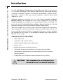
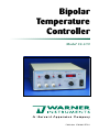
Bipolar
Temperature
Controller
Model CL-100
Publication 5702-001-REV-A
WEEE/RoHS Compliance Statement
EU Directives WEEE and RoHS
To Our Valued Customers:
We are committed to being a good corporate citizen. As part of that commitment,
we strive to maintain an environmentally conscious manufacturing operation. The
European Union (EU) has enacted two Directives, the first on product recycling
(Waste Electrical and Electronic Equipment, WEEE) and the second limiting the use
of certain substances (Restriction on the use of Hazardous Substances, RoHS).
Over time, these Directives will be implemented in the national laws of each EU
Member State.
Once the final national regulations have been put into place, recycling will be offered
for our products which are within the scope of the WEEE Directive. Products falling
under the scope of the WEEE Directive available for sale after August 13, 2005 will
be identified with a “wheelie bin” symbol.
Two Categories of products covered by the WEEE Directive are currently exempt
from the RoHS Directive – Category 8, medical devices (with the exception of
implanted or infected products) and Category 9, monitoring and control instruments.
Most of our products fall into either Category 8 or 9 and are currently exempt from
the RoHS Directive. We will continue to monitor the application of the RoHS
Directive to its products and will comply with any changes as they apply.
• Do Not Dispose Product with Municipal Waste
• Special Collection/Disposal Required
Table of Contents
Warner Instruments
Bipolar Temperature Controller Model CL-100
1
SUBJECT
PAGE
Introduction ..............................................................................3
Nomenclature............................................................................4
Text Conventions ................................................................4
Control Description ..............................................................5-8
Front Panel..........................................................................5
Power Switch (Item A) ................................................................5
Meter Selector Switch and Meter (Item B) ..................................5
Cooling Mode Switch (Item C) ....................................................6
Thermistor Recorder Outputs (Items D, E)..................................6
Monitor Temp In BNC (Item F) ....................................................6
Loop Speed Switch (Item G) ......................................................6
Set Temperature Control (Item H)................................................6
External/Internal Select Control (Item J) ....................................6
Manual Voltage Control (Item K)..................................................7
Peltier Limit LED (Item L) ............................................................7
Freeze Alert LED (Item M) ..........................................................7
Heat / Cool LED’s (Item N) ..........................................................7
Rear panel ..........................................................................8
External Volts Set (Item P) ..........................................................8
External Temp Set (Item Q) ........................................................8
Heater/Cooler input (Item R) ......................................................8
Power Entry Module (Item S) ......................................................8
Ground Terminals (Item T) ..........................................................8
Setup..........................................................................................9
Warner Peltier Driven Systems ..........................................9
Operating With Other Equipment........................................9
Warner Resistive Heating Systems ............................................9
Third-Party Equipment ................................................................9
Thermistor Considerations ..........................................................9
Publication 5702-001-REV-A
www.warneronline.com
Table of Contents (Cont’d)
SUBJECT
PAGE
Operation ..........................................................................10-11
Automatic Mode ................................................................10
Manual Mode ....................................................................11
Appendix ................................................................................12
Specifications ....................................................................12
Accessories and Replacement Parts ................................12
Warranty & Service ..........................................................13-14
Warranty ............................................................................13
Service Notes ..............................................................13-14
Warner Instruments
Bipolar Temperature Controller Model CL-100
2
Publication 5702-001-REV-A
www.warneronline.com
Introduction
Warner Instruments
Bipolar Temperature Controller Model CL-100
3
The CL-100 Bipolar Temperature Controller from Warner Instruments
is a versatile and simple to use thermal control device.This single channel,
automatic controller capable of accurately maintaining a Peltier device
between 0° and 50°C. The unit will also maintain a resistive heater from
ambient to +65ºC.
Although primarily designed for use with Warner In-Line Solution
Heater/Coolers, this instrument can be easily adapted for use with custom-built equipment according to the requirements of the user.When coupled with the SC-20 Dual In-line Solution Heater/Cooler, the CL-100
provides efficient control of perfusion solution temperatures.
The unit is simple to use with a single control for temperature adjustment.
Total automatic control is provided in automatic mode, while manual control is available in manual mode.A loop-speed selector is used to optimize
the response of the system to accommodate thermal delay characteristics
intrinsic to the setup.
Features of the CL-100 Include:
• Quiet operation
• Automatic and manual modes
• Single control temperature adjustment
• Freeze alert
• Built-in protection for Peltier devices
• Selectable loop speed optimizes system speed and stability
• Simultaneous monitoring of system temperature and a separate
point of interest
• Compatible with all Warner Peltier Driven Heater/Coolers
CAUTION:
This equipment is not designed nor
intended for use on human subjects.
Publication 5702-001-REV-A
www.warneronline.com
Nomenclature
4
This manual refers to instrument controls at two functional levels; specific
controls and settings of these controls.To increase readability, we employ
the following text conventions. Since our goal is to provide clarity rather
than complexity, we welcome any feedback you may wish to provide.
• Warner Instrument product numbers are presented using bold type.
• References to controls are specified using CAPS.
• References to control settings are specified using italic type.
• Special comments and warnings are presented in highlighted text.
Any other formatting should be apparent from context.
Warner Instruments
Bipolar Temperature Controller Model CL-100
Text Conventions
Publication 5702-001-REV-A
www.warneronline.com
Control Description
5
Warner Instruments
Bipolar Temperature Controller Model CL-100
Front Panel
A schematic of the face panel of the CL-100 is shown below. Important
components are identified by letter (A-H, J-N). Refer to this diagram as an
aid in identification of the described components.
Power Switch (Item A)
Supplies power to the CL-100.
Meter Selector Switch and Meter (Item B)
THE SELECTOR SWITCH selects the parameter displayed on the associated
METER. Included options are Set Temp, Control Temp, Monitor Temp, and
Output Volts and are described below.
Set Temp reports the adjustment from either the SET TEMPERATURE control (Item H) or the EXT TEMP SET BNC (Item Q). Displayed units are °C.
Control Temp reports the actual temperature of the feedback thermistor situated within the heater/cooler device being used. The data is informative
only and is in units of ºC.
Monitor Temp reports the temperature of the sensor thermistor which connects via the MONITOR TEMP IN BNC (Item F).This provides a convenient
means to determine the temperature of any point of interest within your
setup. Displayed units are ºC.
Output Volts reports the adjustment from either the MANUAL VOLTAGE
control (Item K) or the EXT VOLT SET BNC (Item P). Displayed units are V.
The METER also provides an indication that the main POWER is on.
Publication 5702-001-REV-A
www.warneronline.com
Control Description (Cont’d)
Warner Instruments
Bipolar Temperature Controller Model CL-100
6
Cooling Mode Switch (Item C)
Selects between Automatic or Manual operational modes, or center select
for off.
Thermistor Recorder Outputs (Items D, E)
BNC connectors are provided to send thermistor readings to a data acquisition system or chart recorder.
CONTROL TEMP OUT (Item D) reports the actual temperature of the feedback thermistor situated within the heater/cooler device being used.
Output is calibrated to 100 mV/ºC.
MONITOR TEMP OUT (Item E) reports the temperature of the sensor thermistor which connects via the MONITOR TEMP IN BNC (Item F). Output is
calibrated to 100 mV/ºC.
Monitor Temp In BNC (Item F)
BNC for connecting a sensor thermistor used to sample the temperature at
a point of interest. Designed for use with the TA-29 cable assembly.
Loop Speed Switch (Item G)
Sets the feedback loop speed for the CONTROL TEMP THERMISTOR when
the CL-100 is used in automatic mode. Feedback options include fast,
medium, and slow. Optimally set to fast for most applications but can be
set to medium or slow for systems with longer thermal delay characteristics.
Set Temperature Control (Item H)
Used to adjust the set point of the automatic temperature control system.
The associated GREEN LED is on when the INTERNAL/EXTERNAL SELECT
CONTROL (Item J) is set to internal, and the COOLING MODE SWITCH
(Item C) is set to auto. Set value can be read from the METER (Item B) in
the set temp position.
External/Internal Select Control (Item J)
Used to select between internal or external control inputs when the
instrument is in Manual mode (Item C).
When the INTERNAL/EXTERNAL SELECT CONTROL is set to internal, and
the COOLING MODE SWITCH (Item C) is set to auto, the SET TEMPERATURE CONTROL (Item H) will be active. Setting the COOLING MODE
SWITCH (Item C) to manual disables the SET TEMPERATURE CONTROL
(Item H) and activates the MANUAL VOLTAGE CONTROL (Item K).
Publication 5702-001-REV-A
www.warneronline.com
Control Description (Cont’d)
7
Warner Instruments
Bipolar Temperature Controller Model CL-100
7
Manual Voltage Control (Item K)
Used to manually adjust the voltage output to the heater/cooler device.The
associated GREEN LED is on when the INTERNAL/EXTERNAL SELECT
CONTROL (Item J) is set to internal, and the COOLING MODE SWITCH
(Item C) is set to manual. Set value can be read from the METER (Item B)
in the output volts position.
Peltier Limit LED (Item L)
This option functions only when the CL-100 is used with an SC-20 Dual
In-line Solution Heater/Cooler.The RED LED is lit when the temperature of
the Peltier device within the SC-20 exceeds its operational limits.
Activation of this circuit automatically sets the output voltage of the CL100 to 0 V.
Freeze Alert LED (Item M)
This option functions only when the CL-100 is used with an SC-20 Dual Inline Solution Heater/Cooler. The BLUE LED is lit when the Peltier device
within the CL-100 approaches 0°C.Activation of this circuit is informative
only and will not alter any instrument setting.
Heat / Cool LED’s (Item N)
RED and BLUE LED’s indicate heating or cooling power applied to the
Peltier device.
Publication 5702-001-REV-A
www.warneronline.com
Control Description (Cont’d)
8
Bipolar Temperature Controller Model CL-100
Rear Panel
A schematic of the rear panel of the CL-100 is shown below. Important
components are identified by letter (P-T). Refer to this diagram as an aid in
identification of the described components.
Warner Instruments
External Volts Set (Item P)
Input BNC for the application of a specified voltage to be applied to the
heater/cooler being controlled. Input functions only when the INTERNAL/EXTERNAL SELECT CONTROL (Item J) is set to external, and the
COOLING MODE SWITCH (Item C) is set to manual. Units are 1 V/V input.
Can be used for computer control purposes.
External Temp Set (Item Q)
Input BNC for adjusting the SET TEMPERATURE of the CL-100. Input functions only when the INTERNAL/EXTERNAL SELECT CONTROL (Item J) is
set to external, and the COOLING MODE SWITCH (Item C) is set to auto.
Units are 100 mV/°C. Can be used for computer control purposes.
Heater/Cooler input (Item R)
This is the connection port for Warner Heater/Cooler devices such as the
SC-20 Dual In-line Heater/Cooler.
Power Entry Module (Item S)
Comprised of the line cord attachment point, line voltage selector and fuse
buss. Power entry is selectable between 115 VAC, 60 Hz or 230 VAC, 50 Hz.
The replaceable fuse is 0.4 amp slow-blow for 230 V applications, or 0.8
amp slow-blow for 115 V applications.
Ground Terminals (Item T)
Provides separate connections for chassis and circuit ground. Banana jacks
are bridged when shipped from the factory.
Publication 5702-001-REV-A
www.warneronline.com
Control Description
9
ATTENTION
PLEASE READ BEFORE APPLYING POWER TO YOUR UNIT!!
The unit has been set to be used with 120 VAC.
If the VAC needs to be changed to 220VAC, enclosed you will find a kit
(power cord (1) and fuses (2)) to be used to convert the unit from 120VAC
to 220 VAC.
The unit uses only one fuse; the second one is sent as spare.
Follow these instructions to change the unit(s) from 120VAC or 220VAC:
Power Entry Module
Warner Instruments
Bipolar Temperature Controller Model CL-100
AC Conversion
Fuse holder side view.
Push out drawer to access
the Spare Fuse
Active
Fuse
Step 1
Depending on AC Voltage being
used, turn VAC selector switch
to 110VAC or 220 VAC
Step 2
Carefully, pry open the fuse holder from the inside
by using a small flat screwdriver.
Replace fuse according to voltage being used.
Item # 64-0352 Model CL-100 use:
For 120 VAC: 0.80 Amp - 5x20mm Slow Blow
For 220 VAC: 0.40 Amp - 5x20mm Slow Blow
Publication 5702-001-REV-A
www.warneronline.com
Setup
Warner Instruments
Bipolar Temperature Controller Model CL-100
10
The CL-100 has been designed primarily to drive Warner’s expanding line of
Peltier driven Heater/Coolers.However,the device is also capable of supplying
power to Warner’s full line of resistive heaters (e.g., Series 20 Heater Platforms,
In-line Solution Heaters, etc.).The instrument will auto-detect when a resistive
heating device has been attached and will disable cooling commands.
Warner Peltier Driven Systems
The basic set up for the CL-100 is straightforward when used with Warner’s
Peltier Driven Heater/Coolers.
First connect the cable from the heater/cooler device into the 15-pin D-connector on the back of the CL-100.Then connect the TA-29 Thermistor (supplied with the heater/cooler device) to the MONITOR TEMP IN BNC (Item F).
If using external control inputs, make connections from your command
output (e.g., analog out on the A/D board, power supply) to either the EXT
TEMP SET (Item Q) or EXT VOLT SET (Item P) BNC’s on the rear panel.
Operating With Other Equipment
The CL-100 can be used to power other Warner equipment such as the
SH-27B and SF-28 Slow-Flow solution heaters. In addition, the controller
can be used as an independent device to power third-party equipment as
long as the following considerations are met.
Warner Resistive Heating Systems
Use of the CL-100 to power Warner resistive heaters is allowed if used in
conjunction with the AC-100 adapter cable.When the CL-100 is connected to a resistive device, all command inputs (auto and manual modes for
both internal and external commands) are functional with the exception
that cooling commands are not executed.
Third-party Equipment
The CL-100 heater controller will work with many other heating devices if
used in conjunction with the AC-100 adapter cable. To obtain maximum
heating power, the resistance of the third-party heating element should be
between 8-12 W. However, any element that works at a maximum of 15 V
and 2.4 A will also work with the CL-100.
Thermistor Considerations
The CL-100 heater controller was designed to accommodate Unical thermistors from Thermometrics (Edison, New Jersey). This family of thermistors can be interchanged without recalibration of the instrument.The nominal resistance of Unical thermistors is 10.0 kW at 25ºC.
Other thermistors may be used with the CL-100 if the nominal resistance
also is 10.0 kΩ at 25ºC.
Publication 5702-001-REV-A
www.warneronline.com
Operation
Warner Instruments
Bipolar Temperature Controller Model CL-100
11
The main use of a heater/cooler control device such as the CL-100 is to
maintain a constant bath temperature with minimum deviation from a set
temperature. This is usually achieved by using a thermally controlled chamber/platform or in-line solution heater, or a combination of both.
NOTE: Refer to the front and rear panel schematics on pages 6-9 for orientation of the CL-100 controls.
Automatic Mode
In Automatic Mode, the CL-100 maintains the temperature of the
connected heater/cooler at the value set by the user.
Operation is straightforward. Connect your heater/cooler device and
sensor thermistor as described on page 10. Set the CL-100 to internal
commands by setting the INTERNAL/EXTERNAL SELECT control (Item J)
to internal. Place the CL-100 into auto mode by switching the COOLING
MODE SWITCH (Item C) to auto. Switch the METER (Item B) to Set Temp
and adjust to the desired set-point using the SET TEMPERATURE control
(Item H).
Alternatively, the CL-100 can be commanded using external inputs. Set the
CL-100 to external commands by setting the INTERNAL/EXTERNAL
SELECT control (Item J) to external. In this mode the CL-100 will accept
external temperature settings from the EXT TEMP SET BNC (Item R) on the
instrument rear panel.This input is calibrated to 100 mV/ºC.
The selectable LOOP SPEED control (Item G) is used to adjust the speed of
the feedback loop in the heater/cooler-thermistor system, which controls
the rate of change of the CL-100’s output voltage. Non-Warner heater systems with feedback thermistors can be used in automatic mode provided
they are compatible with the CL-100 requirements.
LOOP SPEED is normally set to fast to provide the shortest cycle time
between the application of power to the heater element and the sensing of
temperature at the thermistor. For heater/cooler-thermistor systems with
long response times, the fast setting will cause the temperature to overshoot the target by a large amount resulting in system oscillation. For this
condition, try medium or slow settings to find the optimum feedback rate.
Publication 5702-001-REV-A
www.warneronline.com
Operation (Cont’d)
12
Warner Instruments
Bipolar Temperature Controller Model CL-100
Manual Mode
In manual mode, the MANUAL VOLTAGE control (Item K) is used to set the
output voltage to a fixed value. In manual mode, the SET TEMPERATURE
control (Item H) is disabled, as is the feedback system of the CL-100.
Operation is again straightforward. Set the CL-100 to accept internal
commands by setting the INTERNAL/EXTERNAL SELECT control (Item J) to
internal. Place the CL-100 into manual mode by switching the COOLING
MODE SWITCH (Item C) to manual. Switch the METER (Item B) to Output
Volts and adjust to the desired set-point using the MANUAL VOLTAGE
control (Item K).
Alternatively, the CL-100 can be commanded using external inputs. Set the
CL-100 to external commands by setting the INTERNAL/EXTERNAL
SELECT control (Item J) to external. In this mode the CL-100 will accept
external voltage commands at the EXT VOLT SET BNC (Item P) located on
the instrument rear panel.
In this mode, the instrument operates as a 0-12 VDC power supply that can
provide up to 1.5 A of current to a device. Use this mode with heater
systems that will operate properly with a fixed voltage and lack feedback
thermistors.
Publication 5702-001-REV-A
www.warneronline.com
Appendix
Warner Instruments
Bipolar Temperature Controller Model CL-100
13
Specifications
Maximum Output Voltage
±15 VDC
Maximum Output Current
2.4 A
Manual Voltage Range
0 to ±15 VDC
Maximum Output Power
18 W into a 8 W load
Power Requirements
100-130 or 200-260 VAC, 50/60 Hz, 80 VA
Power Fuse (5 x 20 mm)
0.8 A Slow-Blow for 100-130 VAC
0.4 A Slow-Blow for 200-260 VAC
Front Panel Input
External thermistor
(BNC, calibrated to 10.0 kW at 25°C )
Front Panel Recorder Outputs
Monitor Temp Out (BNC, 100 mV/°C )
Control Temp Out (BNC, 100 mV/°C )
Rear Panel Inputs
External Temperature Set (BNC, 100 mV/°C )
External Voltage Set (BNC)
Heater/Cooler Device (15-pin D connector)
Temperature Range Peltier
0 to 50°C
Resistive: Ambient to 65°C
Meter Display
3.5 digit LED display of °C or V
Meter Readouts
Set Temperature (°C )
Control Temperature (°C )
Monitor Temperature (°C )
Output Voltage (V )
Enclosure, H x W x D
20.0 x 8.9 x 25.4 cm
Weight
5.6 kg
Accessories and Replacement Parts
Catalog No.
64-1427
Model
Product
ACC-1
Adapter cable for heater only components
Publication 5702-001-REV-A
www.warneronline.com
Warranty & Service
14
Warner Instruments
Bipolar Temperature Controller Model CL-100
Warranty
The model CL-100 is covered by our Warranty to be free from defects in
materials and workmanship for a period of two years from the date of shipment. If a failure occurs within this time, we will either repair or replace
the faulty component(s).
This warranty does not extend to damage resulting from misuse, neglect or
abuse, normal wear and tear, or accident.
This warranty extends only to the original customer purchaser.
IN NO EVENT SHALL HARVARD APPARATUS BE LIABLE FOR
INCIDENTAL OR CONSEQUENTIAL DAMAGES. Some states do not
allow exclusion or limitation of incidental or consequential damages so the
above limitation or exclusion may not apply to you. THERE ARE NO
IMPLIED WARRANTIES OF MERCHANTABILITY, OR FITNESS FOR A
PARTICULAR USE, OR OF ANY OTHER NATURE. Some states do not
allow this limitation on an implied warranty, so the above limitation may
not apply to you.
If a defect arises within the one-year warranty period, promptly contact
your local distributor or Harvard Apparatus, Inc. 84 October Hill
Road Holliston, Massachusetts 01746-1388 using our toll free number 1-800-272-2775 (valid only in the U.S., outside U.S. call 508-893-8999).
Goods will not be accepted for return unless an RMA (returned materials
authorization) number has been issued by our customer service department.The customer is responsible for shipping charges. Please allow a reasonable period of time for completion of repairs, replacement and return.
If the unit is replaced, the replacement unit is covered only for the remainder of the original warranty period dating from the purchase of the original device.
This warranty gives you specific rights, and you may also have other rights
which vary from state to state.
In addition, we can be reached by e-mail at [email protected]
or through the web at www.warneronline.com.
Publication 5702-001-REV-A
www.warneronline.com
Warranty & Service (Cont’d)
15
Warner Instruments
Bipolar Temperature Controller Model CL-100
Service Notes
Please refer all questions regarding service to our Engineering Department.
A) If the instrument POWER light fails to light, check the fuse at
the rear panel (located in the black POWER INPUT MODULE). If the
fuse is found to be defective replace it with a 5x20 mm, 0.8 A,
slow-blow fuse (0.4 A for facilities using 220-240 V line voltages).
If the replacement fuse also fails, please call Warner Instruments
for assistance.
B) Occasionally, a knob on the front panel will loosen after long use.
These are "collet" style knobs and are tightened with a screw located
under the knob cap.To gain access to the adjustment screw, pry the
cap off with a thin bladed screwdriver or similar tool.
C) Should service be required, please contact the factory.The problem
may often be corrected by our shipping a replacement part. Factory
service, if required will be expedited to minimize the customer
inconvenience.
D) Instruments are inspected immediately upon receipt and the
customer is notified if the repair is not covered by the warranty.
Repairs can often be completed in 1-2 days from our receipt of the
instrument.
E) If factory service is required, please observe the following
instructions:
1) Package the instrument with at least 3 inches of cushioning on
all sides. Use the original shipping carton if it is available.
2) Insure the shipment for its full value.
3) Include with the shipment an explanation of the problem
experienced.
IMPORTANT for Customers Outside of the U.S.:
Please contact us before return shipping any goods.We will provide instructions so that the shipment will not be delayed or subject to unnecessary
expense in clearing U.S. Customs.
Publication 5702-001-REV-A
www.warneronline.com