1
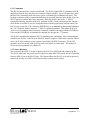
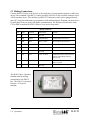
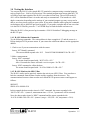
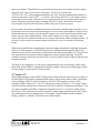
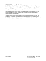
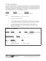
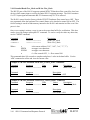
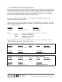
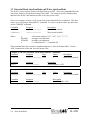
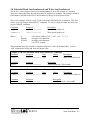
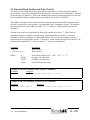
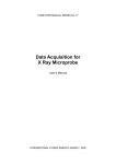
Model
H-4191
RS-232 to SDI-12 Interface Module
Owner's Manual
Version 1.1
(for Revision-C or greater)
D E S I G N
75 West 100 South, Logan, Utah 84321
A N A L Y S I S
Phone: (435) 753-2212
A S S O C I A T E S ,
Fax: (435) 753-7669
I N C.
Web: http://www.waterlog.com E-mail: [email protected]
D E S I G N
75 West 100 South, Logan, Utah 84321
A N A L Y S I S
Phone: (435) 753-2212
A S S O C I A T E S ,
Fax: (435) 753-7669
I N C.
Web: http://www.waterlog.com E-mail: [email protected]
Chapter 1
Operation
1.0 Introduction
The WATERLOG® H-4191 is a RS-232 to SDI-12 gateway (interface) module. When connected
to a personal computer or RS-232 terminal the H-4191 can be used to test and monitor SDI-12
sensors and data recorders. The H-4191 allows a programable logic controller (PLC), remote
terminal unit (RTU) or other data collection device with a RS-232 interface to access SDI-12
sensors. The H-4191 provides the RS-232 to SDI-12 electrical interface, generates the critical
bus timing, parity and command retries needed for the SDI-12 bus protocol..
The “SDI-12 Serial-Digital Interface” is ideal for data logging applications with the following
requirements:
!
!
!
!
Battery powered operation with minimal current drain
Low system cost
Digital sensors output data directly in user units
Sensors are interoperable and available from many different manufacturers
The H-4191 has the following features:
!
!
!
!
!
!
!
!
!
!
!
Provides both electrical and protocol interface functions between RS-232 & SDI-12
Works with any sensor command/response message including vendor specific extended
commands.
Buffers the command so no special timing is required.
Generates proper parity for the SDI-12 bus.
Automatically sends SDI-12 retries.
Passes the sensor service request to the host.
Supports optional CTS/RTS hardware flow control for a slow host device.
Low power mode facilitates use with a RS-232 data radio.
LED shows when the H-4191 is awake.
Built in “sensor” can measure the battery voltage.
Auto-Scan feature supports low-power operation with telemetry radios
The H-4191 is packaged in a rugged plastic enclosure with screw mount ears. Connectors
located on each end provide easy hookup.
H-4191
Operation 1-1
1.1 Applications
Figure 1 shows a monitoring application where a laptop computer is used to monitor the SDI-12
communication between a data recorder and two SDI-12 sensors. Figure 2 shows the connections
when using the H-4191 as a gateway between a PLC and two SDI-12 sensors.
Figure 4 Monitor a data recorder
Figure 3 Interface between a PLC and
two SDI-12 Sensors
1.2 Operation
The H-4191 has a microprocessor with both RS-232 and SDI-12 interface ports. The H-4191
normally operates as a SDI-12 master device: it issues SDI-12 commands and collects responses.
Under certain conditions the H-4191 can respond to host commands itself as a “pseudo” SDI-12
sensor (see Section 1.7).
The RS-232 interface port is connected to a personal computer or other “host” device. The H4191 provides two way communication between the RS-232 host and the SDI-12 bus. During
normal operation, the host device sends an address together with a command to a SDI-12 sensor.
The sensor then replies with a "response".
1-2
Operation
H-4191
1.2.1 Commands
The RS-232 host interface is fixed at 9600 baud. The H-4191 inputs SDI-12 commands (ASCII
characters) from the host and places the character string in a buffer. Up to 128 characters can be
buffered. The command can be sent at any speed, even hand-typed commands will work. The
backspace character (08h) is supported and deletes the previous character in the buffer. Note: the
SDI-12 protocol requires upper case characters. When the H-4191 detects the “!” SDI-12
command terminator character the H-4191 generates a SDI-12 break and transmits the contents
of the buffer to the SDI-12 port in a contiguous burst with the proper parity and bus timing. The
H-4191 also accepts the <CR> character (ENTER Key) as a command terminator and substitutes
the <CR> character with the required “!” SDI-12 command terminator. This makes the H-4191
easier to use for computer users who more commonly complete a message with the ENTER Key.
If you use the ENTER Key to terminate the message, do not type the “!” character.
The H-4191 automatically generates SDI-12 compliant parity and timing. After transmitting the
command, the H-4191 waits for up to 40mS for a sensor response. If the sensor response fails to
arrive, the H-4191 performs a retry sequence specified by the SDI-12 protocol. The H-4191
generates up to four breaks with up to four retries per break (16 retries total). The number of
retries can be programmed (see Chapter 2).
1.2.2 Sensor Response
The response from a SDI-12 sensor is input by the H-4191 at 1200 baud and output to the RS232 port at 9600 baud. Any sensor service requests or other SDI-12 bus traffic are also forwarded
from the SDI-12 port to the RS-232 port. This feature allows the H-4191 to be used to passively
monitor the activity on a SDI-12 bus between a data recorder and its sensors.
H-4191
Operation 1-3
1.3 Making Connections
Connect the RS-232 port of the H-4191 to the serial port of your personal computer or other host
device with a standard 9-pin RS-232 cable (provided). The H-4191 has a female connector and is
a DCE (modem) device. The cable has 9-pin RS-232 connectors which can be plugged directly
into a PC serial port without the use of gender or null-modem adapters. Program your host device
for 9600 baud, 8-bit, no parity, full-duplex communication The host device must assert either
CTS or DSR to awaken the H-4191 from it’s low power sleep mode.
RS-232 Connector
Pin
Name
Direction
Description
Function
1
nc
2
TxD
Output
Transmit Data
Transmit data to host device
3
RxD
Input
Receive Data
Receive data from host device
4
DSR
Input
Data Set Ready
Awakens the H-4191 when asserted.
5
GND
Ground
Ground
6
nc
not used
7
CTS
Input
Clear To Send
Awakens the H-4191 when asserted.
Controls TxD if RTS/CTS flow
control is on.
8
RTS
Output
Request To Send
Asserted when awake and output
buffer is not full
9
nc
not used
not used
The H-4191 has a 4-position
terminal strip for making
connections to the SDI-12
bus. The H-4191 is powered
from the +12V power
terminal.
1-4
Operation
H-4191
1.4 Testing the Interface
You can test the H-4191 with a simple RS-232 terminal or computer using a terminal program
such as SimpleTerm , Xtalk or Hyperterminal. The terminal program must assert either the CTS
or DSR (or both) input signals to the H-4191 to awaken it from sleep. The red LED on the H4191 will be illuminated when it is awake and ready to communicate. The interface is a fullduplex connection, depending on the settings of your terminal program you may or may not be
able to see what you are typing on your screen. If you make a mistake while typing the command,
use backspace key to delete the previous keystroke. If you make a mistake and are not sure what
is in the H-4191's buffer, press the “!” or ENTER Keys to flush the buffer and start over.
When the H-4191 is first powered up it transmits a “H-4191 Initialized” debugging message to
the RS-232 port.
1.4.1 H-4191 Initiates the Commands
Try the following commands. The sensor address in these examples is “0" and the sensor is a
Design Analysis H-350 pressure sensor. If your sensor has a different address use the appropriate
address.
1. Check to see if you can communicate with the sensor.
Issue a “0I!” Identify command.
The sensor should respond with: “012 DAA H-350001S#000000V10<CR><LF>”
2. Make a measurement.
Issue a “0M!” command.
The sensor should respond with: “00153<CR><LF>”
After 14 seconds the sensor will send a service request: “0<CR><LF>
Issue a “0D0" command to collect the data.
The sensor should respond with: “0+4.56+0.0000+0.2<CR><LF>”
1.4.2 H-4191 Monitors the SDI-12 Bus
The H-4191 can be used to passively monitor the activity on a SDI-12 bus. You can observe
both the commands from the data recorder and the responses from the sensors. The
communications between a data recorder and a Model H-350 pressure sensor would appear as
follows:
0M!00153
0D0!0+4.56+0.0000+50.0
In this example the data recorder issued a “0M!” command, the sensor responded with
“00153<CR><LF> “ (sensor 0, measurement time = 015 sec, 3 parameters will be returned).
Next, the data recorder issued a “0D0!” command and the sensor responded with
“0+4.56+0.0000+50.0<CR><LF> (sensor 0, stage = 4.56, PSI = 0.0, temperature = 50.0).
H-4191
Operation 1-5
When monitoring traffic between a data recorder and its SDI-12 sensors, the display may
sometimes have spurious characters which prefix the command. For example:
p0M!00153
p0D0!0+4.56+0.0000+50.0
The lower case “p” in this example was caused by the break pulse generated by the data recorder.
A “break” is a 12mS or longer pulse on the data line which wakes the sensors from their low
power sleep mode. The serial asynchronous receiver transmitter (UART) in the H-4191
misinterprets the break as a random character.
1.5 Low Power Operation
The H-4191 normally reverts to a low power or “sleep” mode. If either the DSR or CTS RS-232
inputs are active (asserted) the H-4191 awakens, powers up its RS-232 transceiver and is
available for full operation. The red LED on the side of the enclosure is illuminated when the H4191 is awake. Most PC terminal programs automatically assert both DSR and CTS by default.
When the H-4191 is connected to a PC the H-4191 will normally awaken and remain awake as
long as it is connected.
1.6 Operation with a Radio
Applications often arise where a SDI-12 sensor must be physically located hundreds or thousands
of feet from the data logger. Transparent wireless SDI-12 bridges are available for these
applications. Unfortunately, transparent bridges can miss or drop measurements because of
corrupted radio packet transmissions. Wireless bridges are problematic because the SDI-12
protocol provides insufficient time to make retries or other recovery.
When coupled with a data radio, the H-4191 can be used to construct a “non transparent”
wireless SDI-12 link. With this architecture the H-4191 is permanently connected to one or more
sensors at the remote site. A pair of RS-232 data radios are installed between the data logger and
the remote H-4191. The radios are normally programmed for “sleep & sniff” low power
operation. When properly configured, the data logger, radios and H-4191 module can provide a
low-power wireless SDI-12 bridge capable of performing retries.
The data logger must be setup to initiate and collect SDI-12 commands/responses from a RS-232
port instead of its normal SDI-12 port. SDI-12 commands from the data logger are forwarded via
the radios to the remote H-4191. When the remote data radio receives an inbound data packet, it
pulses the CTS input which awakens the H-4191 in preparation to receive the inbound message.
When the H-4191 detects the “!” character, it transmits the contents of its buffer to the remote
SDI-12 bus in a contiguous frame with proper parity and bus timing. The H-4191 waits for and
collects any sensor response and forwards it to the radio. The sensor response is sent over the
radios back to the data logger. If one or more of the radio transmissions is lost or corrupted, the
data logger can retry the entire sequence as needed.
The H-4191 has an internal inactivity timer which keeps the module awake to process the service
request and receive subsequent radio packets. If both the RS-232 and SDI-12 ports become
1-6
Operation
H-4191
inactive (and both CTS and RTS are not asserted) for longer than 10-seconds, the timer expires
and the H-4191 enters its low power sleep mode. The H-4191 examines the
“aTTTN<CR><LF>” sensor response initiated by an “aM!” measure command and initializes a
second “keep-awake” timer to TTT + 3-seconds. This ensures the H-4191 will remain awake to
process the service request. When the service request actually arrives, the keep-awake timer is
zeroed. While the keep-awake timer is running the H-4191 sends a null (00h) to the radio
once/second to keep the radio link awake while waiting for the service request.
Be aware that with a point-to-multipoint telemetry architecture, the data logger must take care to
not generate excessive retries when attempting to recover a missed measurement. During a retry
the transmissions are seen by all of the remote stations in the system and will cause them to stay
awake to process the communications. If one remote station were to quit working for some
reason, the extra retry communications causes stress on the batteries of the remaining stations. If
excessive retries are done, the remote stations can fail one by one in a cascade of increasing
retries.
When sleep & sniff radios are employed the host data logger should prefix outbound commands
with 4 or 5 0xFF characters. The 0xFF characters are automatically discarded by the H-4191.
When the remote H-4191 module(s) are awakened by the radio asserting RTS or CTS the H-4191
may miss the first few characters while completing its power-up housekeeping. The 0xFF
preamble characters allow time for the H-4191 to power up and be ready to input and process the
command payload.
The H-4191 also supports a very low power simplex mode for use with telemetry radios where
the H-4191 initiates SDI-12 measurements itself and “pushes” the data to the data logger or host.
See the Chapter 3 (Auto-Scan) for further details.
1.7 Sensor “Z”
When implementing a wireless SDI-12 bridge as described in the previous section it is useful for
the data logger to be capable of monitoring the battery voltage in the remote station. In addition
to functioning as a RS-232 to SDI-12 gateway, the H-4191 has a built-in “sensor” which
responds to SDI-12 address “Z”. The “Z” sensor can measure the H-4191's +12V input voltage,
is used to facilitate turning flow control On or Off and is useful for testing and maintenance. The
“Z” sensor responds to all SDI-12 compliant commands, however, it is only accessible via the
RS-232 port. The built-in sensor will not respond to a data logger connected to the SDI-12 port.
The sensor address can be changed from “Z” to another value if needed with the extended
Change_Address_Command. See Section-2 for further details.
H-4191
Operation 1-7
1.8 RS-232 Hardware Flow Control
The RS-232 port of the H-4191 supports optional RTS/CTS hardware flow control for slow
PLC’s or RTU’s which cannot input or receive the entire SDI–12 response message. The H-4191
monitors its CTS input and transmits RS-232 characters only if CTS is asserted. The H-4191 can
buffer up to 128 SDI-12 response characters, any additional input characters will be lost.
While the H-4191 is busy sending a SDI-12 command or doing retries, it can buffer up to 128
characters from the RS-232 port. The H-4191 de-asserts the RTS output when the buffer is
within 4-characters of becoming full.
The H-4191 comes from the factory with the RTS/CTS hardware flow control set to Off. An
extended SDI-12 command allows the hardware flow control feature to be turned On or Off.
The On/Off setting is stored in Flash memory internal to the H-4191 and remains in effect even if
the power is lost. See Chapter 2 for details.
1-8
Operation
H-4191
Chapter 2
SDI-12 Command and Response Protocol
2.0 SDI-12 Command and Response Protocol
This is a brief description of the Serial Digital Interface (SDI-12) Command and Response
Protocol used by the WATERLOG® Series Model H-4191 sensor. Included is a description of the
commands and data format supported by the H-4191.
Refer to the document "A SERIAL DIGITAL INTERFACE STANDARD FOR HYDROLOGIC
AND ENVIRONMENTAL SENSORS.” Version 1.2 April 12, 1996 Coordinated by the SDI-12
Support Group, 135 East Center, Logan, Utah.
During normal communication, the data recorder sends an address together with a command to
the H-4191 SDI-12 sensor. The H-4191 then replies with a "response." In the following
descriptions, SDI-12 commands and responses are enclosed in quotes. The SDI-12 address and
the command/response terminators are defined as follows:
"a"
Is the sensor address. The following ASCII Characters are valid addresses:
"0-9", "A-Z", "a-z", "*", "?". Sensors will be initially programmed at the
factory with the address of "0" for use in single sensor systems. Addresses
"1 to 9" and "A to Z" or "a to z" can be used for additional sensors
connected to the same SDI-12 bus. Address "*" and "?" are "wild card"
addresses which select any sensor, regardless of its actual address.
"!"
Is the last character of a command block.
"<cr><lf>" Are carriage return (0D) hex and line feed (0A) hex characters. They are
the last two characters of a response block.
Notes:
•
•
•
•
All commands/responses are upper-case printable ASCII characters.
Commands must be terminated with a "!" character.
Responses are terminated with <cr><lf> characters.
The command string must be transmitted in a contiguous block with no gaps of more
than 1.66 milliseconds between characters.
H-4191
SDI-12 Command and Response Protocol 2-1
2.1 Command Summary
The H-4191 supports the following SDI-12 commands:
Standard Commands:
aM!
Make battery voltage measurement
aR0!
Make battery voltage measurement
aD0!
Send Data
aV!
Verify
aI!
Send Identification
a!
Send Acknowledge
aAn!
Change Address
Extended Commands:
aXHELP!
Display the supported commands
aXRFM!
aXWFMn!
Read hardware flow control mode (0=no, 1=yes)
Write hardware flow control mode (0=no, 1=yes)
aXRRT!
aXWRTn!
Read max retries (0=no retries)
Write max retries (0=no retries)
aXRASM!
Read AutoScan mode (0=off, 1=on)
aXWASMn! Write AutoScan mode (0=off, 1=on)
aXRASI!
aXWASIn!
Read AutoScan interval (0 to 65535 seconds)
Write AutoScan interval (0 to 65535 seconds)
aXFAS!
Force AutoScan sequence
aXRTL!
aXWTL!
Read AutoScan task list
Write AutoScan task list
aXTCOP!
Test the COP timer
2-2
SDI-12 Command and Response Protocol
H-4191
2.2 Measure Command
The Measure Command causes a measurement sequence to be performed. Data values generated
in response to this command are stored in the sensor's buffer for subsequent collection using "D"
commands. The data will be retained in the sensor until another "M", " C", or "V" command is
executed.
Command
"aM!"
Response
"atttn<cr><lf>"
Description
Initiate measurement
Where:
a
is the sensor address ("0-9", "A-Z", "a-z", "*", "?").
M
is an upper-case ASCII character
ttt
is a three digit integer (000-999) specifying the maximum time, in seconds,
the sensor will take to complete the command and have measurement data
available in its buffer.
n
is a single digit integer (0-9) specifying the number of values that will be
placed in the data buffer. If "n" is zero (0), no data will be available using
subsequent "D" commands.
Upon completion of the measurement, a service request "a<cr><lf>" is sent to the data recorder
indicating the sensor data is ready. The data recorder may wake the sensor with a break and
collect the data any time after the service request is received or the specified processing time has
elapsed.
Example of a H-4191 "aM!" command:
Command
Response
Time
"ZM!"
"Z0021<cr><lf>"
2 sec
Values
1
Subsequent Command
Response
"ZD0"
Z+12.01<cr><lf>
Description
Make measurement
Where: +12.01 is the battery voltage
H-4191
SDI-12 Command and Response Protocol 2-3
2.3 Concurrent Measurement Command
This is a new command for the Version 1.2 SDI-12 Specification. A concurrent measurement is
one which occurs while other SDI-12 sensors on the bus are also taking measurements. This
command is similar to the “aM!” command, however, the nn field has an extra digit and the
sensor does not issue a service request when it has completed the measurement. Communicating
with other sensors will NOT abort a concurrent measurement. Data values generated in response
to this command are stored in the sensor's buffer for subsequent collection using "D" commands.
The data will be retained in the sensor until another "M", "C", or "V" command is executed.
Command
"aC!"
Response
"atttnn<cr><lf>"
Description
Initiate measurement
Where:
a
C
ttt
nn
is the sensor address ("0-9", "A-Z", "a-z", "*", "?").
is an upper-case ASCII character
is a three digit integer (000-999) specifying the maximum time, in seconds, the
sensor will take to complete the command and have measurement data available in
its buffer.
is a two digit integer (00-99) specifying the number of values that will be
placed in the data buffer. If "n" is zero (0), no data will be available using
subsequent "D" commands.
The data recorder may wake the sensor with a break and collect the data anytime after the
specified processing time has elapsed.
2-4
SDI-12 Command and Response Protocol
H-4191
2.4 Send Data Command
The Send Data command returns sensor data generated as the result of previous "aM!", "aC!", or
"aV!" commands. Values returned will be sent in 33 characters or less. The sensor's data buffer
will not be altered by this command.
Command
"aD0!" through "aD9!"
Response
"apd.d ... pd.d<cr><lf>"
Where:
a
is the sensor address ("0-9", "A-Z", "a-z", "*", "?").
D0..D9
are upper-case ASCII characters.
p
Is a polarity sign (+ or -)
d.d
represents numeric digits before and/or after the decimal. A decimal may
be used in any position in the value after the polarity sign. If a decimal is
not used, it will be assumed to be after the last digit.
For example: +3.29 +23.5 -25.45 +300
If one or more values were specified and a "aD0!" returns no data (<CR><LF> only), it means
that the measurement was aborted and a new "M" command must be sent.
Example of a H-4191 "aD0!" command:
Previous Command
Response
"ZM!"
"Z0021<cr><lf>"
Subsequent Command
Response
"ZD0"
Z+12.01<cr><lf>
Where: +12.01 is the battery voltage
H-4191
SDI-12 Command and Response Protocol 2-5
2.5 Continuous Measurements
This is a new command for the Version 1.2 SDI-12 Specification. Sensors that are able to
continuously monitor the phenomena to be measured, such as a cable position, do not require a
start measurement command. They can be read directly with the R commands (R0!...R9!). The R
commands work exactly like the D (D0!...D9!) commands. The only difference is that the R
commands do not need to be preceded with an M command.
Example of a H-4191 "aR0!" command:
Response
"Z+12.01<cr><lf>"
Previous Command
"ZR0!"
Where: +12.01 is the battery voltage
2.6 Send Acknowledge Command
The Send Acknowledge Command returns a simple status response which includes the address of
the sensor. Any measurement data in the sensor's buffer is not disturbed.
Command
"a!"
Response
"a<cr><lf>"
Where:
a
2-6
Is the sensor address ("0-9", "A-Z", "a-z", "*", "?").
SDI-12 Command and Response Protocol
H-4191
2.7 Initiate Verify Command
The Verify Command causes a verify sequence to be performed. The result of this command is
similar to the "aM!" command except that the values generated are fixed test data and the results
of diagnostic checksum tests. The data generated in response to this command is placed in the
sensor's buffer for subsequent collection using "D" commands. The data will be retained in the
sensor until another "M", "C", or "V" command is executed.
Command
"aV!"
Response
"atttn<cr><lf>"
Description
Initiate verify sequence
Where:
a
is the sensor address ("0-9", "A-Z", "a-z", "*", "?").
V
is an upper-case ASCII character.
ttt
is a three digit integer (000-999) specifying the maximum time, in seconds, the
sensor will take to complete the command and have data available in its buffer.
n
is a single digit integer (0-9) specifying the number of values that will be
placed in the data buffer. If "n" is zero (0), no data will be available using
subsequent "D" commands
Example of a "aV!" command:
Command
"ZV!"
Response
Time
"a0013<cr><lf>" 1 sec
Values
Description
3
Return fixed data and diagnostic data
for testing purposes.
Subsequent Command
Response
"ZD0"
Z+123.456+78.9+y<cr><lf>
Key
+123.456
+78.9
y
Description
Fixed test data
Fixed test data
FLASH checksum test
H-4191
Units
0 = Failed, 1 = Passed
SDI-12 Command and Response Protocol 2-7
2.8 Send Identification Command
The Send Identification Command responds with sensor vendor, model, and version data. Any
measurement data in the sensor's buffer is not disturbed.
Command
"aI!"
Response
"allccccccccmmmmmmvvvxx...xx<cr><lf>"
Where:
a
is the sensor address ("0-9", "A-Z", "a-z", "*", "?").
I
is an upper-case ASCII character.
ll
is the SDI-12 version compatibility level, e.g. version 1.2 is represented as
"12".
cccccccc
is an 8 character vendor identification to be specified by the vendor and
usually in the form of a company name or its abbreviation.
mmmmmm
is a 6 character field specifying the sensor model number.
vvv
is a 3 character field specifying the sensor version number.
xx...xx
is an optional field of up to a maximum of 13 characters to be used for
serial number or other specific sensor information not relevant to operation
of the data recorder.
Example of a "aI!" command:
"a12
DAA H-4191vvvS#nnnnnnVkkk<cr><lf>"
H-4191 implementation of the optional 13 character field:
S#nnnnnnVkkk (12 bytes total)
Where:
"nnnnnn"
is a six character sensor serial number
"kkk" is a three digit sensor firmware revision level
2-8
SDI-12 Command and Response Protocol
H-4191
2.9 Change Sensor Address Command
The Change Sensor Address Command allows the sensor address to be changed. The address is
stored in non-volatile Flash memory within the sensor. The H-4191 will not respond if the
command was invalid, the address was out of range, or the Flash memory programming operation
failed.
Command
"aAn!"
Response
"n<cr><lf>"
Description
Change sensor address
Where:
a
is the current (old) sensor address ("0-9", "A-Z", "a-z", "*", "?"). An ASCII
"*" may be used as a "wild card" address if the current address is unknown
and only one sensor is connected to the bus.
A
is an upper-case ASCII character.
n
is the new sensor address to be programmed ("0-9", "A-Z").
NOTE: To verify the new address use the "Identify Command."
Example of a "Change Sensor Address" command:
Command
Response
"ZA9!"
"9<cr><lf>"
H-4191
Description
Change sensor address to "9"
SDI-12 Command and Response Protocol 2-9
2.10 Extended Read Flow_Mode and Write Flow_Mode
The RS-232 port of the H-4191 supports optional RTS/CTS hardware flow control for slow host
devices which cannot input or receive the entire SDI-12 response message. The H-419 monitors
it’s CTS input signal and transmits RS-232 characters only if CTS is asserted.
The H-4191 comes from the factory with the RTS/CTS hardware flow control set to OFF. These
two commands allow the hardware flow control feature to be checked or turned ON or OFF. The
On/Off setting is stored in flash memory internal to the H-4191 and remains in effect even if the
power is lost.
Once a new setting is written, a copy is sent to the sensor data buffer for verification. This data
can be viewed by using a subsequent "D" command. To read or verify the value any other time,
use the "XRFM" command.
Command
Response
"aXRFM!"
"aXWFMn!"
“a0011<cr><lf>"
“a0011<cr><lf>"
Where:
a
XRFM
XWFM
n
Description
Read Flow_Mode
Write Flow_Mode
is the sensor address ("0-9", "A-Z", "a-z", "*", "?").
are upper case characters.
are upper case characters.
0 = flow control OFF, 1 = flow control ON
This command takes 001 seconds to complete and places 1 value in the data buffer. Use the
“aD0" command to collect and view the current value.
Example of a H-4191 Extended "Read Flow_Control_Mode" command:
Command
Response
Time
Values
Description
"ZXRFM!"
"Z0011<cr><lf>" 1 sec
1
Read Flow_Mode
Command
Response
"ZD0!"
"Z+0<cr><lf>"
Description
Flow Mode = OFF
Example of a H-4191 Extended "Write Flow_Control_Mode" command:
Command
Response
Time
Values
Description
"ZXWFM1!"
"Z0011<cr><lf>" 1 sec
1
Write Flow_Mode
Command
Response
"ZD0!"
"Z+1<cr><lf>"
2-10
SDI-12 Command and Response Protocol
Description
Flow Mode = ON
H-4191
2.11 Extended Read MaxRetry and Write MaxRetry
The H-4191 automatically generates SDI-12 compliant parity and timing. After transmitting the
command, the H-4191 waits for up to 40mS for a sensor response. If the sensor response fails to
arrive, the H-4191 performs a retry sequence specified by the SDI-12 protocol. The H-4191
generates up to four breaks with up to four retries per break (16 retries total). The number of
retries can be examined or changed using these two commands.
In some cases where a wild card address (“*”) is employed with multiple sensors on a bus,
MaxRetry should be set to 0 (no retries).
Once a new setting is written, a copy is sent to the sensor data buffer for verification. This data
can be viewed by using a subsequent "D" command. To read or verify the value any other time,
use the "XRRT" command.
Command
Response
"aXRRT!"
"aXWRTn!"
“a0011<cr><lf>"
“a0011<cr><lf>"
Where:
a
XRRT
XWRT
n
Description
Read MaxRetry
Write MaxRetry
is the sensor address ("0-9", "A-Z", "a-z", "*", "?").
are upper case characters.
are upper case characters.
number of retries
This command takes 001 seconds to complete and places 1 value in the data buffer. Use the
“aD0" command to collect and view the current value.
Example of a H-4191 Extended "Read MaxRetry" command:
Command
Response
Time
Values
"ZXRRT!"
"Z0011<cr><lf>" 1 sec
1
Command
Response
"ZD0!"
"Z+4<cr><lf>"
Description
Read MaxRetry
Description
Do up to 4 retries
Example of a H-4191 Extended "Write Flow_Control_Mode" command:
Command
Response
Time
Values
Description
"ZXWRT0!"
"Z0011<cr><lf>" 1 sec
1
Write MaxRetry
Command
Response
"ZD0!"
"Z+0<cr><lf>"
H-4191
Description
Retries = 0 (no retries)
SDI-12 Command and Response Protocol 2-11
2.12 Extended “XHELP”
This command is used for installation and testing. This command causes the H-4911 to display a
listing of the supported SDI-12 commands. This is not compliant with the SDI-12 specification
and is not used with data loggers.
2-12
SDI-12 Command and Response Protocol
H-4191
Chapter 3
Auto-Scan Mode
3.0 Auto-Scan Mode
The Auto-Scan mode described in this chapter provides support for a simplex telemetry
architecture for collecting data from remote SDI-12 sensors via a wireless link.
Wireless applications often arise where a SDI-12 sensor must be physically located hundreds or
thousands of feet from the data logger. Normal communications with SDI-12 sensors requires up
to five transmissions to complete a measurement sequence:
•
•
•
•
•
Master transmits the SDI-12 command
Slave transmits its response
Slave transmits a service request
Master transmits a SDI-12 data command
Slave transmits its data buffer
If any of these transmissions are corrupted or lost, the sequence must be repeated or “re-tried”.
This sequence must be repeated for every SDI-12 sensor attached to the H-4191. Most telemetry
architectures require the radios to be setup with either a “sleep & sniff” configuration or setup
with the receivers continually powered.
With the Auto-Scan mode, the H-4191 is configured to periodically scan the sensors attached to its
SDI-12 port and transmit (push) the data to the remote host. With this architecture the receivers in
the remote telemetry radios are not used and can be shut off to save power. This scheme provides
for very low power operation with a solar panel. In addition, only one transmission is needed for
each sensor scan. The data from all of the sensors attached to the SDI-12 port of a H-4191 is
concatenated and sent in one transmission.
The pros and cons of the simplex telemetry architecture are as follows:
•
•
•
•
•
The H-4191 is programmed to transmit data on a fixed schedule (such as every 15 minutes).
The H-4191 does not have a real-time clock and has no knowledge of time-of-day.
The data logger or host must accept and parse asynchronous data from the remote site(s).
The data logger cannot schedule or synchronize the measurements.
A data transmission includes the concatenated data from all of the SDI-12 sensors attached to
the SDI-12 port.
The remote telemetry radios can be configured with their receivers powered off.
H-4191
Auto-Scan Mode 3-1
With this telemetry architecture it is recommended the telemetry radios be configured for
Acknowledged service. With acknowledged service the transmitting module listens for an ACK
(acknowledgment). If the transmitting module does not receive the ACK within the allotted time,
it will retransmit the packet. The retransmission is made after a random delay slot to help avoid
collisions. With this scheme, reliable transmission and retries are made by the telemetry radios not the data logger. The 10-second inactivity timer in the H-4191 allows time for the radio the
perform acknowledged service transmissions at the completion of a scan
The Auto-Scan mode is configured with extended SDI-12 commands to the H-4191's built-in
SDI-12 sensor address (“Z”). The “Z” sensor is only accessible via the RS-232 port. The built-in
sensor will not respond to a data logger connected to the SDI-12 port. The sensor address can be
changed from “Z” to another value if needed with the extended ChangeAddressCommand
described in Section-2.
3.1 Task List
When the Auto-Scan mode is activate, the sensor scan is controlled by a “Task List” programmed
into H-4191. The Task List is a simple ASCII string with SDI-12 commands in a comma
separated variable (CSV) format. Depending on the task list any SDI-12 address and any
command can be generated.
The format is as follows: <cmd><"!"><parameter><",">
For example: 0M!1,1M!2,5M!3
In this example a 0M! command is first sent to the SDI-12 port. The response is collected from
sensor “0" and the measurement data from parameter #1 is extracted. Next, the command 1M! is
sent to sensor “1" and the data from parameter #2 is extracted. Finally, the command 5M! is
transmitted and the data from parameter #3 is extracted.
The data from all three measurements is concatenated into one message and sent to the telemetry
radio. Each transmission is prefixed by a "#" character and ends in a <CR><LF> sequence. The
measurement fields are separated by a comma. Each measurement field includes the sensor
number, a "=" character, and the measurement data.
For example: "#0=+12.3,1=-4.5,2=+4.99,3=+1.2<CR><LF>"
The data logger or telemetry host can use the “#” character to frame the message and discard stray
packets. It must parse the message and extract the data fields.
3-2
Auto-Scan Mode
H-4191
3.2 Operation
The Auto-Scan mode is controlled by three settings: AutoScanMode, ScanInterval and the TaskList. These settings are made with extended commands to sensor address “Z” and are described in
the following sections.
The Auto-Scan mode is enabled by setting AutoScanMode=1. When activated, the H-4191 will
awaken from low-power sleep and perform a sensor scan at the interval determined by the ScanInterval setting. The H-4191 has no knowledge of time-of-day and employs a non-temperature
compensated time clock such that the scan time may drift a few seconds each day.
With this data acquisition architecture the data logger will normally time stamp the data, however
the measurement scans cannot be synchronized with other stations or aligned to fixed points of the
clock.
3.3 Extended Force Auto-Scan Command
This command is used for setup and testing and causes the H-4191 to immediately perform an
Auto-Scan sequence. This command works regardless of the AutoScanMode setting.
Command
Response
"aXFAS!"
“a0011<cr><lf>"
Where:
a
XFAS
Description
Force an Auto-Scan sequence
is the sensor address ("0-9", "A-Z", "a-z", "*", "?").
are upper case characters.
Example of a H-4191 Extended Force Auto-Scan command:
Command
Response
"ZXFAS!"
None
H-4191
Auto-Scan Mode 3-3
3.3 Extended Read AutoScanMode and Write AutoScanMode
The H-4191 comes from the factory with Auto-Scan set to OFF. These two commands allow the
Auto-Scan feature to be checked or turned ON or OFF. The setting is stored in Flash memory
internal to the H-4191 and remains in effect even if the power is lost.
Once a new setting is written, a copy is sent to the sensor data buffer for verification. This data
can be viewed by using a subsequent "D" command. To read or verify the value any other time,
use the "XRASM" command.
Command
Response
"aXRASM!"
"aXWASMn!"
“a0011<cr><lf>"
“a0011<cr><lf>"
Where:
a
XRASM
XWASM
n
Description
Read AutoScanMode
Write AutoScanMode
is the sensor address ("0-9", "A-Z", "a-z", "*", "?").
are upper case characters.
are upper case characters.
0 = AutoScan Off, 1 = AutoScan On
This command takes 001 seconds to complete and places 1 value in the data buffer. Use the
“aD0" command to collect and view the current value.
Example of a H-4191 Extended "Read AutoScanMode" command:
Response
Time
Values
Command
"ZXRASM!"
"Z0011<cr><lf>" 1 sec
1
Command
Response
"ZD0!"
"Z+0<cr><lf>"
Description
AutoScanMode = OFF
Example of a H-4191 Extended "Write AutoScanMode" command:
Command
Response
Time
Values
"ZXWASM1!"
"Z0011<cr><lf>" 1 sec
1
Command
Response
"ZD0!"
"Z+1<cr><lf>"
3-4
Auto-Scan Mode
Description
Read AutoScanMode
Description
Write AutoScanMode
Description
AutoScanMode = ON
H-4191
3.4 Extended Read AutoScanInterval and Write AutoScanInterval
The H-4191 comes from the factory with AutoScanInterval set to 900 seconds (15-minutes).
These two commands allow the scan interval to be examined or changed. The setting is stored in
Flash memory internal to the H-4191 and remains in effect even if the power is lost.
Once a new setting is written, a copy is sent to the sensor data buffer for verification. This data
can be viewed by using a subsequent "D" command. To read or verify the value any other time,
use the "XRASI" command.
Command
Response
"aXRASI!"
"aXWASIn!"
“a0011<cr><lf>"
“a0011<cr><lf>"
Where:
a
XRASI
XWASI
n
Description
Read AutoScanInterval
Write AutoScanInterval
is the sensor address ("0-9", "A-Z", "a-z", "*", "?").
are upper case characters.
are upper case characters.
0 to 65535 seconds
This command takes 001 seconds to complete and places 1 value in the data buffer. Use the
“aD0" command to collect and view the current value.
Example of a H-4191 Extended "Read AutoScanInterval" command:
Response
Time
Values
Description
Command
"ZXRASI!"
"Z0011<cr><lf>" 1 sec
1
Read AutoScanInterval
Command
Response
"ZD0!"
"Z+900<cr><lf>"
Description
AutoScanInterval = 900 seconds
Example of a H-4191 Extended "Write AutoScanInterval" command:
Command
Response
Time
Values
Description
"ZXWASI60!"
"Z0011<cr><lf>" 1 sec
1
Write AutoScanInterval
Command
Response
"ZD0!"
"Z+60<cr><lf>"
H-4191
Description
AutoScanInterval = 60 seconds
Auto-Scan Mode 3-5
3.5 Extended Read TaskList and Write TaskList
The Task List is a simple ASCII string with SDI-12 commands in a comma separated variable
(CSV) format. These two commands allow the Task-List to be observed or programmed. The task
list can be up to 32 characters. Note in the example below that a measurement sequence in the task
list can include the battery voltage measurement made by the H-4191 itself (ZM!).
The aXRTL! Command works somewhat like a continuous measurement (aR0!) command where
the data is sent directly in the response. No subsequent “aD0" command is needed. The response
message includes the sensor address (usually “Z”), a “:TaskList=” header and then the task list
characters.
Writing a new task list is complicated by the need to embed one or more “!” SDI-12 end-ofcommand characters within the message string. Without special care the first “!” character
encountered will be interpreted as a command delimiter. To overcome this problem, use the “:”
colon character as a place holder for the “!” characters. When writing the task list, the H-4191 will
automatically substitute the “!” character when a “:” character is encountered.
Command
Description
Read TaskList
Write TaskList
"aXRTL!"
"aXWTLdddddd!"
Where:
a
XRTL
XWTL
ddddd
is the sensor address ("0-9", "A-Z", "a-z", "*", "?").
are upper case characters.
are upper case characters.
is the ASCII task list string
Example of a H-4191 Extended "Read TaskList" command:
Command
Response
"ZXRTL!"
"Z:TaskList=ZM!1,0M!1,1M!2'<cr><lf>"
Example of a H-4191 Extended "Write TaskList" command:
Response
Command
"ZXWTLZM:1,0M:1,1M:2!"
3-6
Auto-Scan Mode
"Z:TaskList=ZM!1,0M!1,1M!2<cr><lf>"
H-4191
Appendix A
Specifications
RS-232 Port
Type:
Asynchronous, 9600 baud, 8-bit, no
parity (fixed)
Flow Control:
RTS/CTS (optional)
Command Buffer: 60 characters
SDI-12 Port
Baud Rate:
1200
Protocol:
SDI-12, 7-bit even parity, 1 stop bit
Output Voltage Levels:
Minimum high level:
3.5 volts
Maximum low level:
0.8 volts
Warranty
The WATERLOG® H-4191 is warranted against defects in
materials and workmanship for two years from date of shipment.
Notes
Specifications subject to change without prior notice due to
ongoing commitment to product testing and improvement.
Internal Voltage Monitor (Address “Z”)
Range:
6-18V
Resolution:
12-bit (.004V)
Accuracy:
±1%
Power Requirements
Voltage Input:
Supply Current:
Sleep Mode
Active
Surge Protection:
200µA typ
25mA typ
Built in, 1.5 KVA
Environmental
Operating Temperature:
Storage Temperature:
-40° C to +50° C
-50° C to +70° C
Mechanical
Material:
Size
Connectors:
RS-232:
SDI-12
9 to 16.0 Volts DC
ABS plastic
3.75" Long x 2.65" Wide x 1.25" Deep
9-Pin, female, D-sub, DCE connections
4-position terminal strip, pluggable,
Phoenix Combicon™
H-4191
Specifications A-1