1
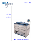
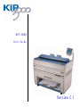
KIP 3000
User Guide
Version C.1
Thank you for purchasing the KIP3000 Multi-Function Printer.
This USER'S MANUAL contains functional and operational explanations for the KIP3000.
Please read this USER'S MANUAL carefully before using the Printer.
Please keep this USER'S MANUAL for future reference.
1. When this product is installed in North America.
This device complies with part 15 of the FCC Rules. Operation is subject to the following two
conditions: (1) This device may not cause harmful interference, and (2) this device must
accept any interference received, including interference that may cause undesired operation.
2. When this product is installed in Europe
This equipment complies with the requirements in Pub.22 of CISPR Rules for a Class B
computing device.
Operation of this equipment in a residential area may cause unacceptable interference to radio
and TV reception requiring the operator to take whatever steps are necessary to correct the
interference.
Do not install Machine around other electronic equipment or other precision instruments.
Other devices may be effected by electrical noise during operation.
If the Machine is installed near other electronic equipment, such as a TV or a radio,
interference to said equipment, such as noise or flickering, may occur.
Use a separate power line and install the PRINTER as far as possible from said equipment.
As an ENERGY STAR ® Partner, Katsuragawa Electric Co., Ltd. has determined
that this product meets the ENERGY STAR ® guidelines for energy efficiency.
The International ENERGY STAR ® Office Equipment Program is an international program that
promotes energy saving through the penetration of energy efficient computers and other office
equipment. The program backs the development and dissemination of products with functions that
effectively reduce energy consumption. It is an open system in which business proprietors can
participate voluntarily. The targeted products are office equipment such as computers, monitors,
printers, facsimiles, copiers, scanners, and multifunction devices. Their standards and logos are
uniform among participating nations.
The symbol shown indicates that this product conforms to Directive
2002/96/EC of the European Parliament and the council of 27 January
2003 on waste electrical and electronic equipment (WEEE) and does not
apply to countries outside of EU.
(1)
Safety Warnings
The following warnings are very important in order to safely use this product.
These notes are important in preventing danger to the operator or operation of the printer.
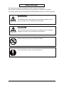
The following symbols are found throughout the USER’S Manual and have the following meaning:
WARNING
This WARNING mark means that there is a possibility of death or serious
injury if you ignore or do not follow the said instruction.
CAUTION
This CAUTION mark means that there is a possibility of injury or physical
damage if you ignore or do not follow the said instruction.
When marked with this symbol, “DO NOT ATTEMPT”
When marked with this symbol, “pay close attention to”
(2)
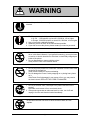
WARNING
Ground the product with a correct ground source or you may be electrically
shocked.
1. The Power source should be as follows:
In U.S.A. : 120V plus6% or minus10%, 50/60Hz, 15A or higher
In Europe : 220-240V plus6% or minus10%, 50/60Hz, 10A or higher
2. Use a circuit with a dedicated breaker.
3. Install the product as close to the wall outlet as possible.
4. If you wish to move the printer, please contact your service personnel.
1. Do not remove the screw and do not open the cover if not instructed to
do so in this User’s Manual. If you ignore this warning, you may be burnt
or receive an electric shock due to a hot item or electrically charged part
inside of the printer.
2. Do not disassemble or tamper with the printer.
It may result in a fire or an electrical shock.
1. Do not plug in the printer into a multi-wire connector in which some other
equipment is plugged into.
It may cause a fire due to outlet overheating.
2. Do not damage the Power Cord by stepping on or placing heavy items
on it.
If the Power Cord is damaged, it may cause a fire or you may receive
an electric shock. REPLACE THE CORD IF DAMAGED!
1. Do not put a flower vase, a flowerpot or any water-filled item on the
product.
Spilt water could cause a fire or an electric shock.
2. If the product generates an abnormal smell or noise, turn it off and
unplug it from the wall electrical outlet immediately.
Do not throw the toner into a fire or other sources of heat, as it can
explode.
(3)
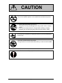
CAUTION
Do not install the printer in a humidified room or a dusty room.
Also, do not install the printer on an unstable floor as injuries may occur.
1. Unplug the printer before you move it.
The power cord may be damaged and it may result in a fire or electric
shock.
2. If you do not use the printer for a long duration (holidays, company
shutdown) turn off and unplug the printer from the outlet for safety.
Do not pull the cord when you unplug the printer as you may damage the
Power Cord.
There are hot items inside of the printer.
Take great care not to touch these items when you remove mis-fed media.
Ventilate the room well if you print in a small area.
(4)
TABLE OF CONTENTS
Section 1
Basic Printer Functions
Section 2
Copy Mode – Mono
Section 3
Copy Mode – Color
Section 4
Scan Mode – Mono
Section 5
Scan Mode – Color
Section 6
Job Info Mode
Section 7
Help – Configuration
Section 8
Windows Drivers
Section 9
AutoCAD Drivers
Section 10 KIP Request
Section 11 KIP PrintNet
Section 12 Reporting Package - PRP
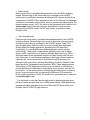
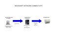
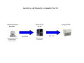
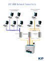
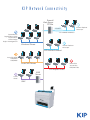
Section 13 Connectivity
(1)
Section 1
Basic Printer Functions
1.0
Before System Use
1.1 Installation Requirements
1.2 Prohibited Originals
1.3 Key Features
1.4 Specifications
1.5 Exterior Views
1.5.1 Front View
1.5.2 Rear View
1.5.3 Operator Panel
Copy Mode
Scan Mode
Job Info Screen
? - Information / Help Screen
1.6 Optional Accessories
1- 1
1- 2
1- 3
1- 4
1- 5
1- 8
1- 8
1- 9
1- 10
1- 10
1- 11
1- 12
1- 13
1- 14
2.0
Operation Details
2.1 Turning on the KIP3000
2.2 Turning off the KIP3000
2.3 Roll Media Replacement
2.4 Toner Installation
2.5 Cut Sheet Media Placement
2.6 Emergency Stop of a Copy or Scan
2.7 Dehumidify the Roll Media (option)
1- 15
1- 15
1- 16
1- 16
1- 21
1- 25
1- 27
1- 28
3.0
Error Messages
3.1 Operational Errors
3. 1. 1 Paper mis-feed errors
3. 1. 1. 1 Deck is jam / Feeding Jam
3. 1. 1. 2 Manual Jam
3. 1. 1. 3 Internal Transport Jam
3. 1. 1. 4 Fuser Jam
3. 1. 1. 5 Accessory Jam
3. 1. 1. 6 Original Jam
3. 1. 2 Others
3. 1. 2. 1 Deck is open
3. 1. 2. 2 Accessory Error
3. 1. 2. 3 Manual Set
3. 1. 2. 4 Cutter Set
3. 1. 2. 5 Toner Empty
3. 1. 2. 6 Paper Empty
3. 1. 2. 7 Door opened during printing
3.2 Call Service Errors
1- 29
1- 29
1- 29
1- 29
1- 32
1- 33
1- 34
1- 35
1- 36
1- 37
1- 37
1- 37
1- 37
1- 38
1- 38
1- 38
1- 39
1- 40
4.0
User Maintenance
4.1 User Maintenance
4. 1. 1 Scanner
4. 1. 2 Print Engine
4. 1. 3 Touch Screen
1- 41
1- 41
1- 41
1- 43
1- 45
1-1
Section 1
Basic Printer Functions
1. 1
Installation Requirements
The following conditions are required for the installation of the equipment.
1. Power source should be rated as:
120V +6% or -10%, 50/60Hz, 15A or higher
2. The equipment must be on a dedicated circuit.
3. The outlet must be near the equipment and easily accessible.
1. Make sure to connect this equipment to a properly grounded outlet.
2. The outlet shall be installed near the equipment and shall be easily accessible.
Site Environmental Conditions
Temperature Range
10 C to 30 C
50 F to 86 F
Humidity Range
20% to 85% RH. (NON CONDENSING)
Keep the printer away from water sources, boilers, humidifiers or refrigerators.
1. The installation site must not have any open flames, dust or ammonia gases.
2. The equipment must not be exposed to the air vents from heating/cooling systems.
3. The equipment should not be exposed to the direct sunlight.
Please draw curtains to block any sunlight.
When you open the printer (Upper Half), do not expose the Photoconductive Drum
to strong (intense) light as this will damage the Drum.
Ozone will be generated while this equipment is in use, although the quantity generated
is within all safe levels. (see certifications) Ventilate the room, if so required.
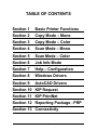
Keep ample space around the equipment to ensure comfortable operation.
(Refer to the following figure.) The floor must be level and the strength must be ample to
sustain the weight of the equipment.
60cm / 24” or larger
when the standard tray is installed
(Rear)
45cm / 18”
or wider
KIP3000
45cm / 18”
or wider
(Front)
80cm / 32” or larger
1-2
Section 1
Basic Printer Functions
1. 2
Prohibited Originals
To duplicate or copy any type of document is not permitted! It may be illegal if you possess copies
of certain types of documents. We recommend you investigate if you have the legal right to copy /
scan a document prior to performing these functions.
Originals prohibited from copying / scanning (by law)
1. You cannot duplicate/copy Currency (Bill, Money, Bank Note, etc.), Government issued
Negotiable Instruments (National Bonds, Security, Local Debt Bonds, etc.).
2. You cannot duplicate/copy Foreign Currency or Foreign Negotiable Instruments.
3. You cannot duplicate/copy unused postal stamps or government postcards without
permission to replicate from the Government.
4. You cannot duplicate/copy Government issued revenue stamps or certificate stamps, which
are issued by Liquor Tax Acts or the Commodity Tax Acts.
Other Notable Items
1. You are warned by the government not to copy / scan, private issued securities (stock
certificate, draft, check, goods ticket, etc.), commutation ticket or book of tickets, excluding that
some specific companies can copy such originals it requires for its own business.
2. We recommend you not freely copy / scan government issued passports, public or private
issued licenses, automobile inspection certifications, ID and tickets (passes or meal).
Law To Reference
Regulations to control fake currency and
bonds.
Control Law against Forged or Fake
Foreign Currency, Bill, Bank Note and Bond
Forged postal stamps control law
Forged revenue stamp control law
Currency similarity securities Control Law
Items Prohibited to Duplicate
Currency (Bill, Money, Bank Note, etc.),
Government issued Negotiable Instruments
(National Bonds, Security, Local Debt Bonds,
etc.)
Foreign Currency or Foreign Negotiable
Instruments
Unused postal stamps or government postcards
Government issued revenue stamps, and
certificate stamps prescribed by Liquor Tax Act
or Commodity Tax Act
Private issued securities (stock, draft, check,
goods ticket, etc.), commutation or book tickets
Originals protected by Copyright
It is prohibited to copy / scan:
books, music, paintings, maps, drawings, movie and pictures which are protected
by copyright.
1-3
Section 1
Basic Printer Functions
1. 3
Key Features
The KIP 3000 is a single footprint Multi-Function Printer which can copy, scan and print.
Advanced drivers and comprehensive print utilities make the KIP 3000 an advanced, easy to use
system. (some functions may be optional)
The scan and print speeds are up to 60mm/sec or up to 4 landscape “D” prints/minute.
KIP HDP technology generates no waste toner.
The combination of the KIP HDP Plus imaging system with mono-component minute toner
produces high definition lines, distinctive greyscale and consistent blacks.
The maximum paper width is 914mm or 36” wide, and the minimum is 279mm or 11”.The
maximum paper length is 3.6m or 11.8’ (with 36” paper), and the minimum is 210mm or 8.5”.
Up to 600dpi print and scan resolutions, with an advanced Image Process System, produces the
highest quality images.
Copier Features
• Easy Touch screen control panel
• Collated Sets copying
• Real-time image preview
• Recall/reprint previous jobs
• 600x600DPI copy quality
• Integrated Accounting and Reports for all copying, network printing, scanning
• Network ready copier
• Simple Operator assistance for every day tasks (toner replacement procedure)
• Image stamping
• All hardware/software included for instant upgrade from Digital Copier to Network
Printer to Scan-to-File system.
• Information center displays all support information, meter readings, and serial number.
• Color Copy to third party inkjet is optional
Network Printer Features (Optional)
• Standard TCP/IP connectivity
• Direct support for vector file formats: HPGL1/2, HP-RTL, Calcomp 906/907
• KIP 3000 DWF format support
• Direct support for raster file formats: TIF Group 3/4, Cals Group 4, Uncompressed
Grayscale/Color TIF,
• Optional KIP 3000 PDF format support: PS/PDF file format.
• Standard Windows Driver for KIP Script (PS output) and KIP-GL (HPGL/2,RTL output)
• Standard AutoCAD Drivers
• Unlimited site license of KIP Request allows users to group supported formats together
for printing collated sets.
• Integrated Accounting in all KIP Drivers/Request for all network printing.
• Integrated KIP 3000 Web Printing (web server)
• Open architecture ASCII Job Ticket for third party applications
Scan-to-File Features
• Scan directly to PDF, TIF Group 4, Cals Group 4
• Scan to file to FTP or personal inbox on the KIP 3000
• Selected resolution – up to 600 DPI optical
• Automatic original size recognition
• Retrieve scanned image files with KIP Request
• Color scanning is optional
1-4
Section 1
Basic Printer Functions
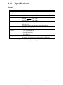
1. 4
Specifications
General
Subject
Model
Configuration
Specification
KIP3000
Console
Maximum power
consumption
Acoustic noise
1500W (Including Scanner & IPS)
Ozone
Dimensions
Weight
Environmental condition
for usage
Input power
Idling
Max. 52db
Printing
Max. 60db
Impulse sound
Max. 65db
Max. 0.1ppm (Measurement method under UL Standard)
1244mm (W) x 600mm (D) x 1100mm (H) or
50” x 24” x 44”
(Operation Panel is not included in these dimensions)
210 kg or 462 lbs (1 roll)
217 kg or 478 lbs (2 roll)
Temperature:
10 to 32 Centigrade or
50 to 86 Fahrenheit
Humidity:
20 to 85% RH
In U.S.A. : 120V plus/minus 10%, 50/60Hz, 10A
In Europe : 220-240V plus 6% or minus 10%, 50/60Hz, 6A
NOTE : specifications subject to change without notice
1-5
Section 1
Basic Printer Functions
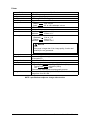
Printer
Subject
Specification
Model
Configuration
Printing method
Photoreceptor
Print speed
KIP 3000
Console – Single Footprint
LED Array Electro-Photography
Organic Photoconductive Drum
60mm per second
(Metric)
2 A0 / minute
(Inch)
2 E or 4 D Landscape / minute
LED Array – Calibrated
600dpi x 600dpi
Maximum
914mm or 36”
Minimum
279mm or 11”
Maximum
(Standard)
3.6m or 11.8’
(Option)
24m or 75’
Minimum
210mm or 8.5”
Print head
Resolution
Print width
Print length
NOTE
If the page is longer than 3.6m, image quality, function and
reliability are not guaranteed.
Warm up time
First print time
Fusing method
Development method
Media
Storage of consumables
Less than 5
24 seconds (D Landscape)
32 seconds (E)
Heat - Pressure Rollers
Dry, non-magnetic mono-component toner
Plain Paper
64 to 80g/m2 - US Bond (20lbs)
Tracing Paper
US Vellum (20lbs)
Film
4 MIL
Recommend media for electro-photography process
Store toner from 0 to 35 C ( 32 to 95 F ) and within the humidity
range from 10 to 85% RH.
NOTE : specifications subject to change without notice
1-6
Section 1
Basic Printer Functions
Scanner
Subject
Scanning method
Light source
Setting of original
Starting point of scan
Scan width
Specification
Contact Image Sensor (CIS) (5 – A4)
LED
Face up
Center
Max. : 914.4mm or 36”
Min. : 275.0mm or 11”
Transportable original
Max. : 932.2mm or 36.7”
width
Min. : 275.0mm or 11”
Scan length
Max. : 3.6m or 19.7’ (Including the margin area)
Min. : 210mm or 8.5” (Including the margin area)
Margin area
3mm from leading edge and trailing edge
Optical resolution
600dpi
Digital resolution
Max. : 600dpi
Min. : 100dpi
Original transportation
Sheet through type
Transportable original
Max. : 0.65mm
thickness
Min. : 0.05mm
NOTE : specifications subject to change without notice
1-7
Section 1
Basic Printer Functions
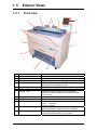
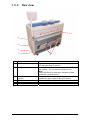
1. 5
Exterior Views
1. 5. 1
Front view
6
5
4
7
3
8
2
9
1
10
11
No.
1
2
3
4
Name
Main Switch
Original Guides
User Interface
Emergency Stop Button
5
6
7
Original Return Guides
Scanner
Original Table
8
9
10
Engine Unit Levers
Cut Sheet - Bypass
Roll Deck
11
Print Tray
12
Counter
12
Function
Turns on / off the KIP 3000.
Assists the user to feed originals into the scanner.
Operation Panel, with many user operations.
Press this button when you would like to stop copying or
scanning in an emergency situation.
Guides return the originals to the user.
Images the original for all scans or copies.
Open this cover to replace the Toner Cartridge.
Place the original to feed into the Scanner to make a
scan or copy.
Press up on the handles to open the printer engine.
Feeds a sheet of cut sheet media.
Roll media installed here.
1 Roll - standard
2 Rolls - optional.
Copies / prints are placed here. (standard configuration)
Optional Stacking / Folding devices are available
Counts the total amount printed.
(also see Operational Panel - Info Screen)
1-8
Section 1
Basic Printer Functions
1. 5. 2
Rear view
1
2
3
4
5
No.
1
Name
Exit Cover
2
LAN Port
3
Dehumidify Heater Switch
(Option)
Inlet Socket
Breaker
Print Guide Trays
4
5
6
6
Function
Open the Exit Cover when you remove the paper
mis-fed inside of the Fuser Unit.
Connect the LAN Cable here to connect the KIP3000 to
the network. (Do not connect a telephone line.)
Note:
There may also be a serial port in this area for folder
connection ( optional device )
Turn on the Dehumidify Heater with this switch when you
would like to dry the paper in the humid season.
Connect the Power Cord here.
It is possible to shut off supplying the AC power.
These trays guide the prints to the Print Tray.
1-9
Section 1
Basic Printer Functions
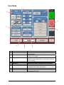
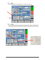
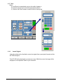
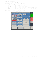
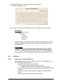
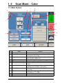
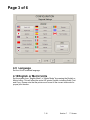
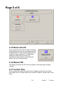
1. 5. 3
Operator Panel
Copy Mode
4
3
5
6
7
2
8
9
10
11
12
1
No.
1
Name
Mode
2
Media
3
Original Type
4
5
6
Quality
Copy Count
Advanced Settings
7
Reset
8
9
View Last
Recall Job
10
11
12
Interrupt
Zoom
Log Off
Function
Selects the “Mode” of the system. (Copy Mode for this
screen shown)
Displays Media type and quantity installed. Includes Cut
Sheet Functions and Media Selection
User Selects the type of original to copy. Also select
Eng/Arch Modes here. (Color Copy is selected here if
enabled)
Select Auto or Manual Image adjustments
Select the quantity of prints and sets designation.
Invert , mirror, stamps, folds, and edge adjustments
preformed / displayed in this button (sub screen)
Clears the image buffer and resets the system to default
settings.
The last scan / job can be viewed
Images can be recalled from the last job for reprint.
Please note that a time limit may be set to recall or this
feature may be disabled by the administrator to prevent
any unauthorized copies.
Pauses the network print jobs to print any copy jobs
Manual and automatic zoom ratios set.
Log off current user if Accounting enabled
1-10
Section 1
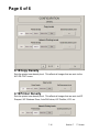
Basic Printer Functions
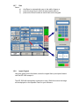
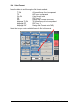
Scan Mode
7
4
3
8
2
9
5
6
1
No.
1
Name
Mode
2
Original Size
3
Original Type
4
5
6
7
Quality
Resolution
Format
Advanced Settings
8
9
Reset
Mailbox
Function
Selects the “Mode” of the system. (Scan Mode for this
screen shown)
Use automatic settings or manually set width, length and
rotation of the images.
User Selects the type of original to copy. Also select
Eng/Arch Mode selected here. (Color Scan is selected
here if enabled)
Select Auto or Manual Image adjustments
Scroll through image resolution (DPI) of the scanner.
Scroll through file formats.
Invert, mirror, stamps, and edge adjustments preformed
/ displayed in this button (sub screen)
Resets the system to default settings.
Select where the image will be stored after the scan
(local setting, FTP etc.).
1-11
Section 1
Basic Printer Functions
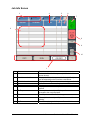
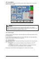
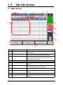
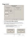
Job Info Screen
3
4
5
6
7
2
8
9
10
1
No.
1
Name
Mode
2
User Name – Job #
3
4
5
6
Media Information
Status
Type
Total
7
To Top
8
Pause
9
Delete
10
Up/Down
Function
Selects the “Mode” of the system. (Job Mode for this
screen shown)
Display the User and any user info of the job ID. A job
can be selected for other functions noted below.
Displays Width, Type and amount remaining per roll deck
Shows the current status of a job and media selection.
Displays a copy or network print job
Displays the total number of prints and current number
printed.
After a job is selected (see #2) the position can be
changed to the next job printed.
Pauses printer to allow media change, etc
After a job is selected (see #2) it can be removed from
printing.
Scrolls through pages in the queue if so available.
1-12
Section 1
Basic Printer Functions
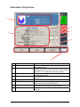
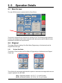
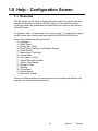
Information / Help Screen
4
3
5
6
2
7
8
1
No.
1
Name
Mode
2
Meter – Versions
3
KIP Contact
4
User Guide
5
6
Configurations
Print This Screen
7
Service
8
Color Config
Function
Selects the “Mode” of the system. (Info/Help Mode for
this screen shown)
Display the current meter counts as well as all
Software/Firmware versions, IPS number, Host Name/IP
(The area may vary depending on KIP printer model)
Shows the contact information for the KIP Service and
KIP Supplies provider.
User Guides for details on system functions and
operations.
Allows user “set up” of the system.
Allows the current screen with version and counter
values to be printed on the KIP printer.
Allows advanced “set up” of the system. Usually for
technical purposes only. Pass-code required.
Configures the optional color scan and color copy
features.
1-13
Section 1
Basic Printer Functions
1. 6
Options - Accessories
Please contact your Authorized Reseller for the following options available for the KIP 3000:
1) Network Printing
Adds the functions of network printing (TCP/IP) from Windows and CAD applications. Includes
Windows/PS drivers, AutoDesk Drivers, “Request” job submission utility and “KIP PrintNet” for
web based submissions.
2) Color Copy to Inkjet
Allows color copy to a third party wide format inkjet device.
3) Monochrome Scanning
Adds the function of scan to file, local IPS drive, local LAN PCs or FTP sites in a variety of file
formats.
4) Color Scanning
Scan to file in color to a local IPS drive, local LAN PCs or FTP sites in a variety of file formats.
5) PDF / PS Printing
Allows direct PDF and Postscript file format printing from various applications including KIP
Request.
6) Roll Deck 2
Second roll of media for increased productivity
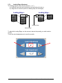
7) Print Tray - Slant Stacker - Vertical Stacker
To accommodate a larger quantity of prints than the standard front feeding print tray, rearward
stacking systems are available for the KIP 3000.
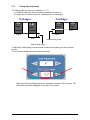
8) Folding (KIPFold)
Fan and crossfold function for copies and network prints.
9) Dehumidifier
Roll Deck Dehumidifier for locations with excess or high humidity
All KIP 3000 options and accessories are subject to change without notice. Please contact your
local Authorized Reseller for details on current available options for the KIP 3000.
1-14
Section 1
Basic Printer Functions
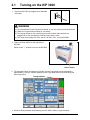
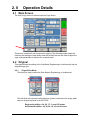
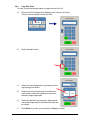
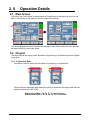
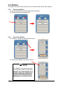
2.1
Turning on the KIP 3000
1. Ensure the KIP 3000 is plugged into a dedicated
wall outlet.
WARNING
(1) Do not handle the Power Plug with wet hands, or you may receive an electrical shock.
(2) Make sure to ground the machine for your safety.
(3) Do not plug the printer into a multi-plug connector in which other devices are
plugged into. It may overheat the outlet and may result in a fire.
(4) The outlet must comply with 120V, plus 6% & minus 10%, 15A, and 50/60Hz
2. There is a Power Switch on the right side of
KIP3000.
Switch to the “ I ” position to turn on the KIP3000.
Power Switch
3. The Operation Panel commences to operate, and the Copy Mode Screen will appear in
approximately 1 minute. A Ready Indicator on the Copy Mode Screen will flash during the
warm up process.
Ready Indicator
4. When the Ready Indicator stops flashing, the KIP 3000 is ready to copy/scan/print.
1-15
Section 1
Basic Printer Functions
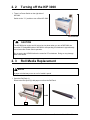
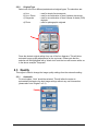
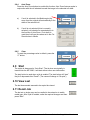
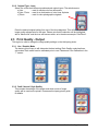
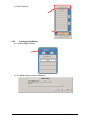
2. 2
Turning off the KIP 3000
1. There is a Power Switch on the right side of
KIP3000.
Switch to the “ O ” position to turn off the KIP 3000.
Power Switch
CAUTION
The KIP3000 print engine and UI look to be shut down when you turn off KIP3000, the
controller PC embedded inside of KIP3000 is still operating for shutdown in approximately
two minutes after Power Switch operation.
Do not unplug the KIP3000 before the controller PC’s shutdown. Doing so may damage
data or the device.
2. 3
Roll Media Replacement
NOTE
A paper mis-feed may occur as a roll of media is spend.
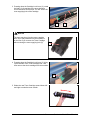
1. Open the Roll Deck (1).
Remove the Roll Spool (2) with paper core from the Roll Deck.
2
1
1-16
Section 1
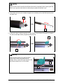
Basic Printer Functions
NOTE
Please confirm that the machine has finished the printing completely before opening the Roll
Deck. If you open the deck while its is still printing, a paper mis-feed will occur.
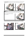
2. Press down the Lever (3) to release the paper core, and then pull out the Roll Spool (2) from
the paper core.
3
2
3. Loosen the knob (4), slide the position of Paper Guide (5) according to the width of roll paper
you will set the Paper Guide (5) tightening the knob (4).
5
4
NOTE
There are Size Guides (6) on the Roll Spool.
As the Paper Guide is provided with the
triangle mark (7), place the Paper Guide so that
the triangle meets the line of Size Guide.
7
6
1-17
Section 1
Basic Printer Functions
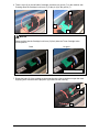
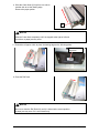
4. Pressing down on the Lever (3), insert the Roll Spool (2) to the core of new roll paper.
2
3
NOTE
Be careful of the winding direction of the roll paper at this time.
5. Install the Roll Spool with new roll paper to the
Roll Deck.
6. Insert the leading edge of roll paper under the Guide Plate (8) until the edge touches the
feeding roller. Then rotate the Paper Feeding Knob (9) clockwise so that the feeding rollers
catch the roll paper.
8
9
1-18
Section 1
Basic Printer Functions
NOTE
For Roll 2, rotate the Paper Feeding Knob
on the rear side (10).
10
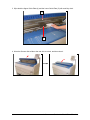
7. When the feeding rollers catch the paper, pull the middle of the Guide Plate 6 (11) out.
Rotate the Paper Feeding Knob (9) again until the leading edge comes out in 8”.
Leading edge
of roll paper
11
9
8. Slide the Cutter Knob (12) fully from one side to
another side to cut the leading edge.
Remove the paper portion.
12
NOTE
Slide the Cutter Knob completely until it is stopped at the right or left end.
If not, a paper jam may occur.
1-19
Section 1
Basic Printer Functions
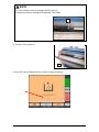
9. Rewind the roll paper to place the leading edge as the following photo.
Place the leading
edge here.
10. Close the Roll Deck (1).
1
NOTE
Be sure to close the Roll Deck fully until it is locked at the correct position.
A paper jam may occur if it is not locked firmly.
11. On the Operator Panel, a screen will automatically appear after the deck is closed to define the
media width and type. Please select the width, and type for each roll deck and then select the
“OK” button to confirm the selection.
1-20
Section 1
Basic Printer Functions
2. 4
Toner Installation
When toner installation is required, the Operator Panel will display a “Toner Required” screen
(in the “Copy” and “Job Info” Screens)
To replace the toner cartridge, please follow these steps:
Please note that the replacement procedure can also be displayed on the Operator Panel for
easier access, by pressing “User Guide : Changing Toner” on the screen)
1. Open the Toner Hatch (1).
1
2. Slide the green Lever (2) to the right to unlock the Toner Cartridge.
(Lever (2) is held automatically.)
2
1-21
Section 1
Basic Printer Functions
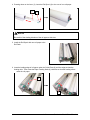
3. Pressing down the Cartridge Lock Lever (3), rotate
the body (4) of cartridge to the arrow direction
a few revolutions until it stops. You will “close” the
toner supplying hole of the cartridge.
3
4
NOTE
The toner may drop from the toner supplying
hole, and it may scattered into the machine or
on the floor if you remove the Toner Cartridge
without closing the toner supplying hole (5).
5
4. Pressing down the Cartridge Lock Lever (3), bring
up the left side of the Toner Cartridge first , and
then remove the whole cartridge from the machine.
3
5. Shake the new Toner Cartridge several times left
and right to make the toner smooth.
1-22
Section 1
Basic Printer Functions
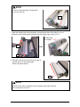
6. There is a pin (6) on the left side of cartridge, and there is a groove (7) on the machine side.
Pressing down the Cartridge Lock Lever (3), fit the pin (6) to the groove (7).
6
3
7
NOTE
Please confirm that the Cartridge Lock Lever (3) firmly locks the Toner Cartridge at the
correct position.
Good
No good
Press down completely.
7. Rotate the body (3) of the cartridge to the arrow direction a few revolutions to open the toner
supplying hole. Confirm that the projection (8) if fitted into the notch (9).
8
9
4
1-23
Section 1
Basic Printer Functions
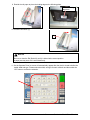
NOTE
It is not necessary to lock the cartridge with the Lever (2).
It rotates and locks the cartridge with closed the Toner Hatch.
2
8. Close the Toner Hatch (1).
1
9. Press “OK” on the Operator Panel to continue copying or printing.
1-24
Section 1
Basic Printer Functions
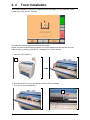
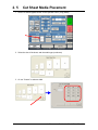
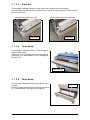
2. 5
Cut Sheet Media Placement
1. Select Cut Sheet Bypass Button on the Operator Panel. (Copy Mode)
2. Select the size of the sheet, and the media type (not shown)
3. Or use “Custom” to select a width.
1-25
Section 1
Basic Printer Functions
4. Select a standard length or use a “Custom Length”.
5. Confirm the cut sheet size by pressing enter.
6. Open the Cut Sheet Feeder (1).
1
1-26
Section 1
Basic Printer Functions
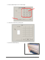
6. There are size markings on the table.
Insert the cut sheet paper on the table along with the associated size mark, and then insert
it into the Feeder referencing the size marks.
When the paper is inserted far enough, the machine automatically sets the paper at the
proper position.
7.
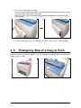
2. 6
Continue with normal copy / print functions. See User Guide “Copy” or “Print” sections.
Emergency Stop of a Copy or Scan
If ever so required, press the Stop Button (1) on the Scanner to immediately stop the original while
making a copy or a scan.
1
1-27
Section 1
Basic Printer Functions
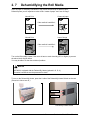
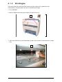
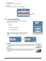
2. 7
Dehumidifying the Roll Media
If the roll paper is extremely humidified, it may cause several kinds of defective print.
Defective prints you will experience most will be “crease of paper” and “loss of image”.
Crease of paper
Normal Print
If the media is humidified ;
Loss of image
Normal Print
If the media is humidified ;
Turn on the Dehumidify Heater if the room air has too much humidity (65% or higher) to prevent
the above kinds of print defect.
You may be able to fix the above kinds of problem.
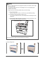
NOTE
KIP3000 is equipped with the Dehumidify Heater (optional in U. S. A.)
If needed, contact the service personnel for detail.
To turn on the Dehumidify Heater, press the H side of the Dehumidify Heater Switch on the rear.
(Press its L side to turn off.)
H (ON)
L (OFF)
Dehumidify Heater Switch
1-28
Section 1
Basic Printer Functions
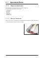
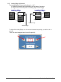
3. 1
3. 1. 1
Operational Errors
Paper mis-feed errors
Some message will be indicated on the LCD in case of a paper jam.
Any of the following messages will be indicated.
Feeding Jam
Manual Jam
Reg. Jam
Internal Jam
Fuser Jam
Accessory Jam
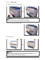
3. 1. 1. 1
Deck jam / Feeding Jam
Either of “Deck is jam” or “Feeding Jam” is indicated when the roll paper is mis-fed in the Roll Deck.
1. Open the Roll Deck, and then rewind the roll paper.
1-29
Section 1
Basic Printer Functions
2. Insert the leading edge of roll paper under the under the Guide Plate (1) until the edge touches
the feeding roller.
Then rotate the Paper Feeding Knob (2) clockwise so that the feeding rollers catch the roll
paper.
1
2
NOTE
The leading edge should be trimmed with a cutter in case of an extreme crease.
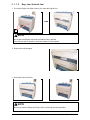
For Roll 2, rotate the Paper Feeding Knob
on the rear side (3).
3
7. When the feeding rollers catch the paper, fold the middle of the Guide Plate 6 (4) outside.
Rotate the Paper Feeding Knob (2) again until the leading edge comes out in 100 millimeters.
Leading edge
of roll paper
4
2
1-30
Section 1
Basic Printer Functions
4. Slide the Cutter Knob (5) fully from one side to
another side to cut the leading edge.
Remove the paper portion.
5
NOTE
Slide the Cutter Knob completely until it is stopped at the right or left end.
If not there, a paper jam may occur.
5. Rewind the roll paper a little to place the leading edge as the following photo.
Place the leading
edge here.
6. Close the Roll Deck.
NOTE
Be sure to close the Roll Deck fully until it is locked at the correct position.
A paper jam may occur if it is not locked firmly.
1-31
Section 1
Basic Printer Functions
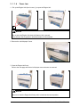
3. 1. 1. 2
Manual Jam
1. Pull up the Lever 2 (1) to open the Engine Unit.
1
NOTE
Do not open the Engine Unit when the Scanner Unit is opened.
If the Scanner Unit is opened, it will hit the bottom of User Interface.
2. Remove the mis-fed paper pulling frontward.
3. Close the Engine Unit.
NOTE
Be sure to close the Engine Unit firmly until it is locked at the correct position.
The mis-fed paper can be replaced with a new one, or be inserted at the opposite edge to
the feeder. An extreme crease may cause a paper jam.
1-32
Section 1
Basic Printer Functions
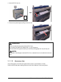
3. 1. 1. 3
Reg. Jam / Internal Jam
1. Pull up the Engine Unit Open Levers (1) to open the Engine Unit.
1
NOTE
Do not open the Engine Unit when the Scanner Unit is opened.
If the Scanner Unit is opened, it will hit the bottom of User Interface.
2. Remove the mis-fed paper.
3. Close the Engine Unit firmly.
NOTE
Be sure to close the Engine Unit firmly until it is locked at the correct position.
1-33
Section 1
Basic Printer Functions
3. 1. 1. 4
Fuser Jam
1. Pull up the Engine Unit Open Levers (1) to open the Engine Unit.
1
NOTE
Do not open the Engine Unit when the Scanner Unit is opened.
If the Scanner Unit is opened, it will hit the bottom of User Interface.
2. Remove the mis-fed paper if seen.
3. Close the Engine Unit firmly.
Refer to the next page when the mis-fed paper cannot be seen or removed.
NOTE
Be sure to close the Engine Unit firmly until it is locked at the correct position.
1-34
Section 1
Basic Printer Functions
4. Open the Exit Cover (2).
2
5. Remove the jammed paper pulling to the rear side.
WARNING
There are extremely hot parts inside the Exit Cover.
Do not touch any parts in the Heater Unit. or you will be burnt.
Also be careful not to get burnt when you touch the printing paper as it may be very hot.
NOTE
If removed a mis-fed paper inside the Exit Cover, scattered toner can be adhered to the next
print.
3. 1. 1. 5
Accessory Jam
The printing paper is mis-fed in the optional device such as Auto Stacker or Folder.
Remove the mis-fed paper making reference to the User’s Manual of concerning device.
1-35
Section 1
Basic Printer Functions
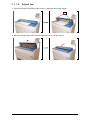
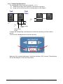
3. 1. 1. 6
Original Jam
1. Open the Scanner Unit pulling up the Levers (1), and then remove the original.
1
2. Move the Scanner Unit to the rear side slightly to unlock, and then close it.
1-36
Section 1
Basic Printer Functions
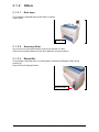
3. 1. 2
Others
3. 1. 2. 1
Deck open
This message is indicated when the Roll Deck is opened.
Close it firmly.
Roll Deck
3. 1. 2. 2
Accessory Error
Any error occurs in the optional device such as Auto Stacker or Folder.
Clear the error making reference to the User’s Manual of concerning device.
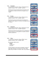
3. 1. 2. 3
Manual Set
This message is indicated when a cut sheet paper is inserted to the Bypass Feeder during
warming up.
Remove it from the Bypass Feeder.
Bypass Feeder
1-37
Section 1
Basic Printer Functions
3. 1. 2. 4
Cutter Set
This message is indicated when the Cutter Knob is not located at the correct position.
Open the Roll Deck, and slide the Cutter Knob fully to the left or right to align the Cutter Knob with
the end of the railing.
Incorrect (Not placed at the end)
Correct (Placed at the left or right end)
Cutter Knob
3. 1. 2. 5
Cutter Knob
Toner Empty
This message is indicated when the Toner Cartridge is
emptied with the toner.
Replace the Toner Cartridge with the new one making
reference to [2. 4 Replacement of Toner Cartridge] on
the page 2-10.
Toner Cartridge
3. 1. 2. 6
Paper Empty
This message is indicated when the roll paper in use is
emptied.
Replace roll paper with the new one making reference to
[2. 3 Replacement of Roll Paper] on the page 2-5.
1-38
Roll paper
Section 1
Basic Printer Functions
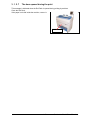
3. 1. 2. 7
The door opened during the print
This message is indicated when the Roll Deck is opened during printing by accident.
Close the Roll Deck.
If the paper is mis-fed inside the machine, remove it.
Roll Deck
1-39
Section 1
Basic Printer Functions
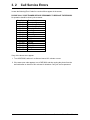
3. 2
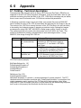
Call Service Errors
In case the following Error Codes for a serious failure appear in the screen;
PLEASE CALL YOUR TRAINED SERVICE PERSONNEL TO RESOLVE THE ERRORS.
No operation should be done by the customer.
Error Code
E - 000
E - 001
E - 002
E - 003
E - 010
E - 011
E - 012
E - 020
E - 031
E - 032
E - 033
E - 034
E - 040
E - 050
E - 070
Error Indication
Fuser Low Temp
Fuser Over Temp
Fuser Low Temp
Temp Not Rise
Motor1 Error
Motor2 Error
Motor3 Error
Counter Error
1st Error
AC Error
Tr Error
Bias Error
Cutter Error
FPGA Error
Dev Error
If any of the above errors appear:
1. Turn off KIP3000, and turn it on after an interval of 3 minutes or more.
2. If the same error code appears, turn off KIP3000, and then unplug the printer from the
wall outlet after an interval of four minutes for shutdown. Call your service personnel.
1-40
Section 1
Basic Printer Functions
4. 1
User Maintenance
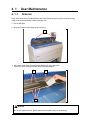
4. 1. 1
Scanner
Clean each Scan Glass, Feeding Rollers and Guide Plates once per a week, as the scan/copy
image may become defective if these parts are dirty.
1. Turn off KIP3000.
2. Open the Scanner Unit pulling up the Levers (1).
1
2. Wipe each Scan Glass (2) and Feeding Rollers (3) with a soft cloth.
Use equal volume mixture of water and a neutral detergent.
3
2
3
NOTE
Do not use organic solvent, glass cleaner and anti-static spray for the cleaning.
1-41
Section 1
Basic Printer Functions
3. Wipe both the Upper Guide Plate (4) and the Lower Guide Plate (5) with a soft dry cloth.
4
5
4. Move the Scanner Unit a little to the rear side to unlock, and then close it.
1-42
Section 1
Basic Printer Functions
4. 1. 2
Print Engine
Clean each Guide Film and Guide Plate once per a week, as the toner or paper dust may
accumulates on such part which may result in a defective print image.
1. Turn off KIP3000.
2. Open the Engine Unit pulling up the Engine Unit Open Levers (1).
1
2. Wipe each Guide Film (2) and Guide Plate (3) with a soft dry cloth to remove the toner or paper
dust.
2
3
1-43
Section 1
Basic Printer Functions
NOTE
(1) There is a Photoconductive Drum (large green cylinder) in the machine, which is right
above the Guide Film.
You will have to replace the Drum if it is damaged, as it is a very important part in
creating the print image.
Please take care of the following matters when you make cleaning.
a.) Do not touch the drum.
Adhering a fingermark or sebum on the Drum may cause defective printing.
b.) Take off such metal accessories as watch or ring.
You will have to replace the Drum if you damage the Drum scratching with such
accessories.
c.) Do not leave the Upper Unit open for more than 10 minutes as the Drum is very
sensitive to light. (Direct sunlight is very harmful.)
Photoconductive Drum
(2) Do not use water, organic solvent and alcohol for the cleaning.
3. Close the Engine Unit.
1-44
Section 1
Basic Printer Functions
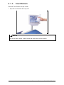
4. 1. 3
Touch Screen
Clean the Touch Screen once per a week.
1. Wipe the Touch Screen with a dry cloth.
NOTE
Do not use water, alcohol, organic solvent and glass cleaner for the cleaning.
1-45
Section 1
Basic Printer Functions
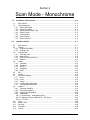
Section 2
Copy Mode - Monochrome
1. 0
Copy Mode - Monochrome............................................................................................. 2- 3
1.1
Main Screen - General ................................................................................................. 21.2
Simple Copying ............................................................................................................ 21.2.1 Select Copy Mode .................................................................................................... 21.2.2 Select Size Mode ..................................................................................................... 21.2.3 Select Original Image Type ...................................................................................... 21.2.4 Copy Count .............................................................................................................. 21.2.5 Media........................................................................................................................ 21.2.6 Length ...................................................................................................................... 21.2.7 Size .......................................................................................................................... 21.2.8 Insert Original ........................................................................................................... 22. 0
3
4
4
4
5
5
6
6
7
7
Operation Details ............................................................................................................ 2- 8
2.1
Main Screen ................................................................................................................. 2- 8
2.2
Original......................................................................................................................... 2- 8
2.2.1 Original Size Mode ................................................................................................... 2- 8
2.2.2 Original Type ............................................................................................................ 2- 9
2.3
Quality .......................................................................................................................... 2- 9
2.3.1 Automatic ................................................................................................................. 2- 9
2.3.2 Threshold ................................................................................................................. 2-10
2.3.3 Density ..................................................................................................................... 2-10
2.3.4 Sharpness ................................................................................................................ 2-10
2.3.5 Dither........................................................................................................................ 2-10
2.4
Copy Count .................................................................................................................. 2-11
2.4.1 Arrows - Count Increase / Decrease ....................................................................... 2-11
2.4.2 Number Pad - Count Increase / Decrease ............................................................... 2-11
2.4.3 Set Copy................................................................................................................... 2-11
2.4.4 Clear......................................................................................................................... 2-12
2.5
Advanced Settings ...................................................................................................... 2-13
2.5.1 Mirror ........................................................................................................................ 2-13
2.5.2 Invert ........................................................................................................................ 2-13
2.5.3 Fold .......................................................................................................................... 2-14
2.5.4 Stamp ....................................................................................................................... 2-15
2.5.5 Leading Edge Adjustment ........................................................................................ 2-16
2.5.6 Trailing Edge Adjustment ......................................................................................... 2-17
2.6
Width ............................................................................................................................ 2-17
2.6.1 Auto .......................................................................................................................... 2-18
2.6.2 Manual Roll Selection............................................................................................... 2-18
2.6.3 Enabling Cutsheet .................................................................................................... 2-19
2.6.4 Cut Sheet ................................................................................................................. 2-19
2.6.5 Copying to Multiple Cutsheets.................................................................................. 2-20
2.6.6 Media Remaining ..................................................................................................... 2-20
2.6.7 Installing Roll Media ................................................................................................. 2-21
2.7
Length .......................................................................................................................... 2-22
2.7.1 Auto .......................................................................................................................... 2-22
2.7.2 Standard................................................................................................................... 2-22
2.8
Size – Zoom ................................................................................................................. 2-24
2.8.1 Preset Percentages.................................................................................................. 2-25
2.8.2 Percentage Key Pad ................................................................................................ 2-25
2.8.3 Page Size Zoom....................................................................................................... 2-26
2-1
Section 2
Copy Mode - Monochrome
2.8.4 Auto Zoom................................................................................................................ 2-27
2.8.5 Clear......................................................................................................................... 2-27
2.9
Start.............................................................................................................................. 2-27
2.10 View Last...................................................................................................................... 2-27
2.11 Recall Job .................................................................................................................... 2-27
2.12 Stop / Reset ................................................................................................................. 2-28
2.13 Interrupt........................................................................................................................ 2-28
2.14 Rescan ......................................................................................................................... 2-28
2.15 Log Off ......................................................................................................................... 2-28
2-2
Section 2
Copy Mode - Monochrome
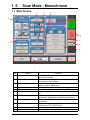
1. 0
Copy Mode - Monochrome
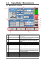
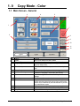
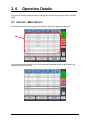
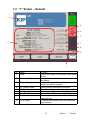
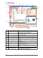
1.1 Main Screen - General
4
5
6
3
7
2
8
9
10
11
12
13
1
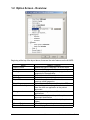
No.
1
Name
Mode
2
Media
3
Original Type
4
5
6
Quality
Copy Count
Advanced Settings
7
Reset
8
9
View Last
Recall Job
10
11
12
13
Interrupt
Zoom
Log Off
Length
Function
Selects the “Mode” of the system. (Copy Mode for this
screen shown)
Displays Media type and quantity installed. Includes Cut
Sheet Functions and Media Selection
User Selects the type of original to copy. Also select
Eng/Arch Modes here. (Color Copy is selected here if
enabled)
Select Auto or Manual Image adjustments
Select the quantity of prints and sets designation.
Invert , mirror, stamps, folds, and edge adjustments
preformed / displayed in this button (sub screen)
Clears the image buffer and resets the system to default
settings.
The last scan / job can be viewed
Images can be recalled from the last job for reprint.
Please note that a time limit may be set to recall or this
feature may be disabled by the administrator to prevent
any unauthorized copies.
Pauses the network print jobs to print any copy jobs
Manual and automatic zoom ratios set.
Displayed if Accounting enabled to Log off current user
Sets the length of the copy
2-3
Section 2
Copy Mode - Monochrome
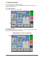
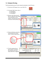
1.2 Simple Copying
To copy, please follow these basic steps. The following chapters have details on
adjustments and parameters that the user can change to modify the copies as
required.
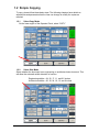
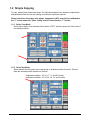
1.2.1
Select Copy Mode
On the lower region of the Operator Panel, select “COPY”.
1.2.2
Select Size Mode
Select whether the document is an engineering or architectural size document. This
will allow the automatic width detection to function.
Engineering widths = 34, 22, 17, 11, and 8.5 inches
Architecture widths = 36, 30, 24, 18, 12, and 9 inches
2-4
Section 2
Copy Mode - Monochrome
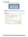
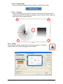
1.2.3
Select Original Image Type
Set the original image type you will copy. The selections are:
Line
- used for simple line documents
Line / Photo - used for a combination of lines & photos documents
Grayscale - used for a combination of lines & areas of shade (CAD)
originals
Photo
- used for photographic originals
This will allow automatic image quality adjustments for the scan.
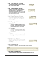
1.2.4
Copy Count
Press the arrow buttons to scroll through the number of copies required or press
on the actual number to set the quantity with the number pad.
2-5
Section 2
Copy Mode - Monochrome
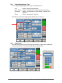
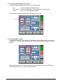
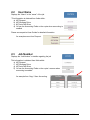
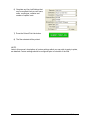
1.2.5
Media
Selects automatic (for best possible fit) or manual roll selection.
or
1.2.6
Length
Select Auto for automatic cut length (to the length of the original) or Standard Cut
for a manual length. (A number pad will request the desired length to be entered)
2-6
Section 2
Copy Mode - Monochrome
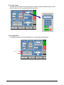
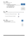
1.2.7
Size
Select
a)
AutoZoom to automatically zoom to the width of paper or
b)
press the arrow keys to scroll through presets ratios or
c)
press on the Zoom number to enter a ratio on the key pad
1.2.8
Insert Original
Using the guides on the feed table, center the original face up and push forward
until the KIP 3000 accepts it.
The KIP 3000 will automatically commence to copy. While this occurs the image
will be displayed on the Operator Panel for your reference.
2-7
Section 2
Copy Mode - Monochrome
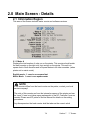
2. 0
Operation Details
2.1 Main Screen
The main Copy screen is selected with the Copy Button.
This screen contains all user functions for copying. The following pages details the
functions and settings of each button and sub screens that can be used to adjust the
copy mode parameters to achieve the required result.
2.2 Original
This region allows the setting of the Size Mode (Engineering or Architectural) and the
original image type.
2.2.1
Original Size Mode
This button is used to select the Size Mode of Engineering or Architectural.
This will allow the automatic width detection system to determine the image width
when an original is placed in the KIP 3000.
Engineering widths = 34, 22, 17, 11, and 8.5 inches
Architectural widths = 36, 30, 24, 18, 12, and 9 inches
2-8
Section 2
Copy Mode - Monochrome
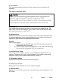
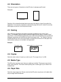
2.2.2
Original Type
Select one of the four different predetermined original types. The selections are:
a) Line
b) Line / Photo
c) Grayscale
d) Photo
- used for simple line documents
- used for a combination of lines & photos documents
- used for a combination of lines & areas of shade (CAD)
originals
- used for photographic originals
Press the desired original setting from one of the four diagrams. This will allow
automatic image quality adjustments for the next scan. Please note that the
selection will be highlighted with a “black circle” and the icon will become white, as
in the above example “Grayscale”.
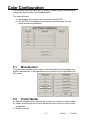
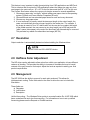
2.3 Quality
This region is used to change the image quality settings from the automatic setting.
2.3.1
Automatic
For most copies, “Auto” should be selected. This will allow the copier to
automatically determine the best image settings without any user intervention
(please also note “Original” in 2.2)
2-9
Section 2
Copy Mode - Monochrome
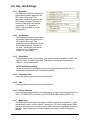
2.3.2
Threshold
To override the “Automatic” settings, “Threshold” can be
adjusted. Deselect “Auto” to enable “Threshold”.
Pressing the arrows manually adjusts the threshold. This
will suppress or enhance the lines and images from the
original.
2.3.3
Density
To override the “Automatic” settings, “Density” can be
adjusted. Deselect “Auto” to enable “Density”.
Pressing the arrows manually adjusts the background
density. This will suppress or enhance the background from
the original.
2.3.4
Sharpness
To override the “Automatic” settings, “Sharpness” can be
adjusted. Deselect “Auto” to enable “Sharpness”.
Pressing the arrows manually adjusts the line sharpness to
remove rough lines or when photos are copied to allow for
smoother graduations.
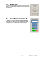
2.3.5
Dither
To override the “Automatic” settings, “Dither” can be
adjusted. Deselect “Auto” to enable “Dither”.
By pressing the dither button,
a) None
b) Fine
c) Medium or
d) Course
This will change how the dots are arranged to create the
final image of the copy. For fine lines a “Course” dither
pattern may be desired. For Photos “None” may be desired.
2-10
Section 2
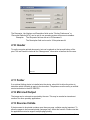
Copy Mode - Monochrome
2.4 Copy Count
In this region the number of copies, and set copy / collation can be set.
2.4.1
Arrows - Count Increase / Decrease
Use the arrows to increase or decrease the total numbers of copies desired by one
with each press of the button.
In this example the arrow was pressed seven times to reach “8 copies”.
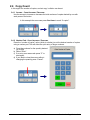
2.4.2
Number Pad - Count Increase / Decrease
Press the “number of copies” value (which is a button) to set the desired number of
copies using a number pad. This will allow the quick entry of larger numbers.
a) Press the numbers for the quantity desired.
(up to 999)
b) Select “Enter”.
c) If an entry error was made press “C” to start
again.
d) If you wish to close the screen without
changing the quantity press “Cancel”.
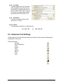
2.4.3
Set Copy
a) To enable collated sets or copy sets to be printed select the Set Copy button.
b) As originals are scanned, the total number in the set is displayed.
2-11
Section 2
Copy Mode - Monochrome
c) Copying will not commence until the set is closed. To close a set, press the start
button. The set with the total number of copies will be printed.
Originals
An example of Set Copy:
3 originals with 3 sets or copies
1
2
3
.
Copies
2.4.4
Clear
Press the clear button to reset the quantity to “1”.
2-12
Section 2
Copy Mode - Monochrome
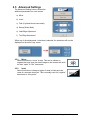
2.5 Advanced Settings
The Advanced Setting button contains the
additional parameters on a sub screen:
a) Mirror
b) Invert
c) Fold (if optional device connected)
d) Stamp (Water Mark)
e) Lead Edge Adjustment
f) Trail Edge Adjustment
When any of the adjustments / selections is selected, the selections will now be
displayed on the main Copy screen
2.5.1
Mirror
Select this button to “mirror” a scan. This can be utilized on
originals that may have the actual image on the reverse side such
as older “sepia” or “film” documents.
2.5.2
Invert
Select this button to change a region of white to black and visa
versa of a scanned document. This is normally used for “negative”
documents or “blue prints”.
2-13
Section 2
Copy Mode - Monochrome
2.5.3
Fold
Select “Fold” to display the fold sub screen. This will allow the selection of a “Fold
Pattern” to be applied to the copy.
a) Use the Arrow buttons to scroll through
the available folds and select a desired
fold from the list.
b) The fold selected will be displayed in the button.
c) Select OK.
NOTE
The list of “Folds” is loaded into Copy Mode by the system administrator or key operator.
They can not be altered or modified in any manner on the UI.
Please contact these persons for any additional stamps that may be required.
Please see “KIP Request” for these functions.
An optional KIP Folder must be purchased to enable these functions.
2-14
Section 2
Copy Mode - Monochrome
2.5.4
Stamp
Select “Stamp” to display another sub screen. This will allow the selection of a
“Stamp” or “Water Mark” to be placed on the scanned image. It will be imbedded into
the image.
a) Use the Arrow buttons to scroll through
the available stamps and select the
desired stamp from the list.
b) The Stamp button will now display the stamp selected.
c) Select OK.
NOTE
The list of “Stamps” is loaded into Copy Mode by the system administrator or key
operator. They can not be altered or modified in any manner on the KIP printer’s
UI.
Please contact these persons for any additional stamps that may be required.
Please see “KIP Request” for these functions.
2-15
Section 2
Copy Mode - Monochrome
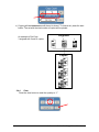
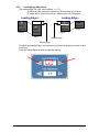
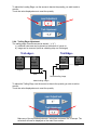
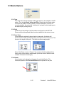
2.5.5
Leading Edge Adjustment
The leading edge of a copy can be altered. ( +/- 4” )
a) additional void area can be placed on the lead edge of a scan or
b) image can be removed (such as a binding strip or a file hanger)
Leading Edge +
Leading Edge -
KIP
Image
Image
KIP
Image
KIP
Scanner
Image
Original
Scanner
Scanner
Scanner
Copy
Original
Copy
Deleted image
Added margin
To adjust the Leading Edge, use the arrows to denote the quantity you wish to add
or remove.
Touch the value displayed area to reset the quantity.
2-16
Section 2
Copy Mode - Monochrome
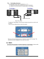
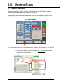
2.5.6
Trailing Edge Adjustment
The trailing edge of each copy can be altered. ( +/- 4” )
c) Additional void area can be placed on the bottom of a copy or
d) Image can be removed (such as a binding strip or a file hanger)
Trail edge +
Trail Edge -
KIP
KIP
KIP
KIP
Image
Image
Image
Image
Scanner
Scanner
Scanner
Copy
Original
Original
Copy
Deleted trailing image
Added trailing margin
To adjust the Trailing Edge, use the arrows to denote the quantity you wish to add
or remove.
Touch the value displayed area to reset the quantity.
Make any of the required adjustments / selections and press “OK” to accept. The
selections will now be displayed on the main Scan screen.
2.6 Width
This region allows automatic or manual roll selection, roll size display, cut sheet media,
the roll amount remaining and to set the installed media type and width.
2-17
Section 2
Copy Mode - Monochrome
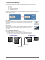
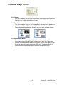
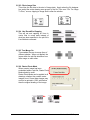
2.6.1
Auto
This default setting allows the copier to automatically select the best media roll
width to print the image onto. It selects the roll noting the amount of image area to
prevent surplus media consumption. (applies to the option - two or more roll model)
Example:
22” original
36” and 24” bond media installed
Original is 22” wide
36” installed
24” Installed
excess non-imaged media
has the best image to media fit
therefore this roll will be used
2.6.2
Manual Roll Selection
To select a roll deck, press the roll deck desired. Note that the roll information is
displayed in the roll deck button.
2-18
Section 2
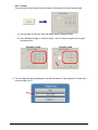
Copy Mode - Monochrome
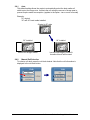
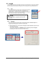
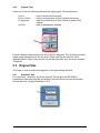
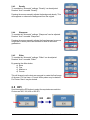
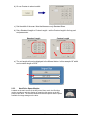
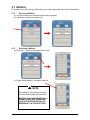
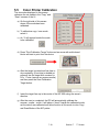
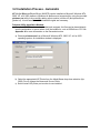
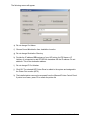
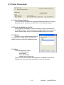
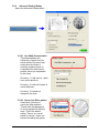
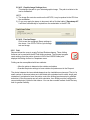
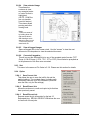
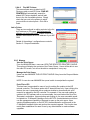
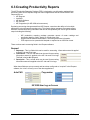
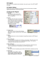
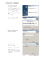
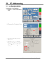
2.6.3
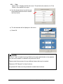
Enabling Cutsheet
Some KIP printers are equipped with a cut sheet feeder that can be enabled in the
configuration menu of the UI.
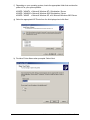
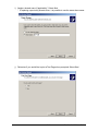
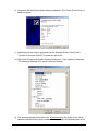
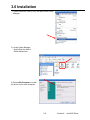
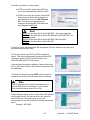
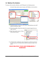
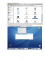
This can be accomplished by following these steps
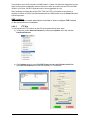
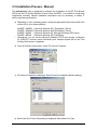
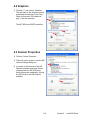
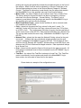
1. Select the (?) button in the bottom left corner of the user
interface.
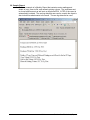
2. Select the Configuration button from the Info/Help screen.
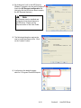
3. Using the Left/Right arrows located at the bottom of the
page scroll to page four (4).
4. Change the Enable Cut Sheet button to “Yes”.
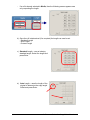
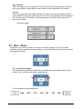
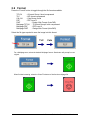
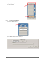
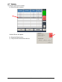
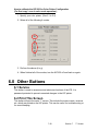
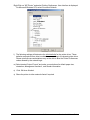
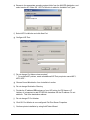
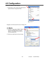
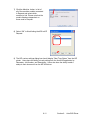
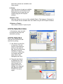
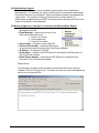
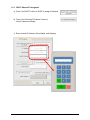
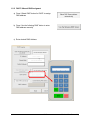
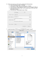
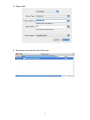
2.6.4
Cut Sheet
To copy onto a cut sheet of media:
a)
Select the CUT SHEET button on the main screen.
b)
Select the Output Size of the actual cut sheet paper that will be inserted into
the Cut Sheet feeder.
2-19
Section 2
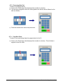
Copy Mode - Monochrome
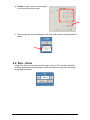
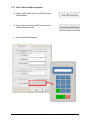
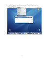
Select desired settings from the main copy screen. Feed your original (s) into the
KIP 3000.
c)
Prepare Cut Sheet Feeder on your printer and WAIT until prompted by the UI.
d)
Insert the original into the Cut Sheet Feeder.
Note:
Only one cut sheet may be fed at a time and this function will time out after 3
minutes if no paper is inserted.
Note:
DO NOT insert the cut sheet media into the feeder while printing from a roll deck,
as this may cause the printer to jam.
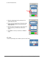
2.6.5
Copying to Multiple Cutsheets
1. Follow steps above (2.6.4)
2. After a short period of time the Printer will beep notifying the user to insert the
cutsheet into the Cutsheet feeder, the Job Info button will also flash be flashing.
3. Once the cutsheet has been printed there will be a short pause and the printer
will start to beep again. Insert the next cutsheet into the printer
4. Continue for multiples.
Note:
Only one cutsheet may be fed at a time and will time out after 3 minutes if no paper
is inserted.
Note:
DO NOT insert the cut sheet media into the feeder while printing from a roll deck,
as this may cause the printer to jam.
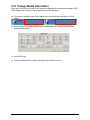
2.6.6
Media Remaining
The installed roll information is displayed in the button of the particular roll deck.
Beside each deck is a volume of media that currently is left on the roll of media.
Indicators will display full, ¾, ½, ¼ or empty.
2-20
Section 2
Copy Mode - Monochrome
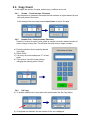
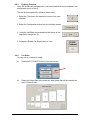
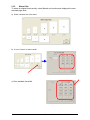
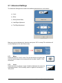
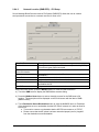
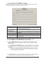
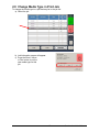
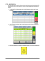
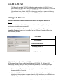
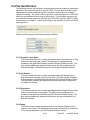
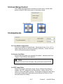
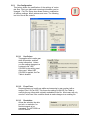
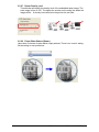
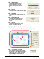
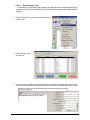
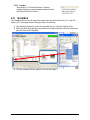
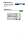
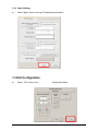
2.6.7
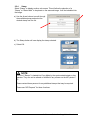
Installing Roll Media
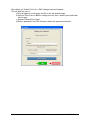
When media is replaced or installed, a screen will automatically appear. This
screen allows the setting of the media type and width. Please see the KIP Printer’s
manual for the procedures to replace a roll of media.
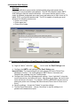
a) If no changes are required, press cancel
b) If changes are required from the currently settings displayed, select the correct
media type and size for each deck and press OK.
This screen shows 36” bond for deck one and 30” Bond for Roll 2 deck. Scroll
through the media choices at the bottom of each roll. Click on the graphical
scissors to trim the desired roll deck.
Media types settings noted above can be changed at any time by pressing the
Media button on the main Copy Screen.
2-21
Section 2
Copy Mode - Monochrome
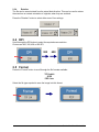
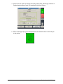
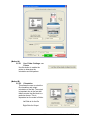
2.7 Length
Two methods determine the length of the copy in the KIP printer. These two methods
are Auto (may also be known as Synchro Cut or Automatic Cut) and Standard Cut.
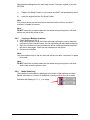
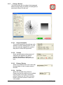
2.7.1
Auto
This mode allows the media length to be determined by the
original length. This also takes into consideration any
enlargements or reductions that are applied to an image as
well, to prevent excess media without image.
NOTE
Auto Length works in conjunction with Auto Roll
noted in 2.6.1.
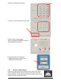
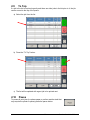
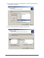
2.7.2
Standard
This mode allows the media length to be determined by a standard length or a
length set manually by the user with a number pad.
a) Select Standard Cut. A sub screen will appear. When Standard is used, the roll
must also be selected.
- If Auto Roll is selected in the Media region the following screen will appear,
prompting the media to be selected. Select the roll.
2-22
Section 2
Copy Mode - Monochrome
-
If a roll is already selected in Media, then the following screen appears now
only requesting the length.
b) Once the roll is determined (if so required) the length can now be set.
- Standard Length
- Auto Length
- Custom Length
c) Standard Length – use an industry
standard length. Select the length and
press Enter.
d) Auto Length – uses the length of the
original to determine the copy length.
Select and press Enter.
2-23
Section 2
Copy Mode - Monochrome
e) Custom Length – set the custom length
in the key pad and press enter
f) The cut length will now be displayed in the main Copy screen in the Standard Cut
button.
2.8 Size – Zoom
Image size / Zoom can be altered in this region on the UI. This includes automatic
zooming, predetermined percentages, or ratio calculations to page size, and simply
percentage increments.
2-24
Section 2
Copy Mode - Monochrome
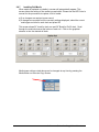
2.8.1
Preset Percentages
The KIP printer has several predetermined industry standard zoom percentages
used for quick access. These can be access with the arrow buttons.
The pre-programmed percentages are:
50 - 66.7 - 70.7 - 100 - 141 - 150 - 200
2.8.2
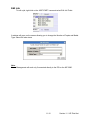
Percentage Key Pad
To enter a percentage directly into the UI,
a)
Press on the Percentage value displayed (the number is a button).
b)
This will show a keypad to enter the value. (Please note that the button
Manual on the side is a default.)
c)
Press the desired zoom value and press enter.
2-25
Section 2
Copy Mode - Monochrome
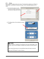
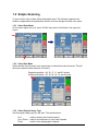
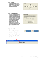
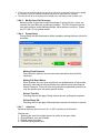
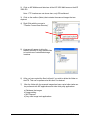
2.8.3
Page Size Zoom
To enter a zoom percentage based on pages sizes into the UI:
a)
Press on the Percentage value displayed (the number is a button).
This will show a keypad to enter the value.
b)
Select Standard button.
c)
Select the original page size by pressing onto the
original page size button.
d)
Please note either Engineering or Architectural
mode can be utilized by pressing on the button
below the original page size.
e)
Select the desired Copy page size. Again please
note either Engineering or Architectural mode can
be utilized.
f)
Press Enter to confirm your selections or Cancel to restart.
2-26
Section 2
Copy Mode - Monochrome
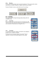
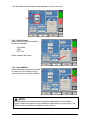
2.8.4
Auto Zoom
Press the Auto Zoom bottom to enable this function. Auto Zoom features works in
conjunction with the roll selected to scale the image to the selected roll width.
a)
If a roll is selected in the Media region the
zoom from the original will automatically fit the
width of the selected roll.
b)
If a roll is not selected (Auto is currently
selected), roll selection is requested prior to
the function of Auto Zoom. If cut sheet is
used then it will use the values set in the Cut
Sheet button in Media.
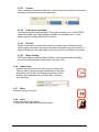
2.8.5
Clear
To reset the percentage value to default, press the
“C” button.
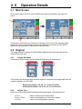
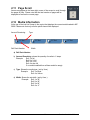
2.9 Start
The copier is always set to “Auto Start”. That is when an originally is
inserted into the KIP 3000, it will start without other user intervention.
The start button is used when a job is recalled. The start button will “start”
the job if depressed after ‘Recall”. (The name will change to “Re-print”)
2.10 View Last
The last documented scanned to be copied be viewed.
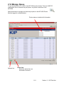
2.11 Recall Job
The last set or single copy can be recalled to be resized or to switch
media type. After a job is recalled, make the required changes and then
press “Start”.
2-27
Section 2
Copy Mode - Monochrome
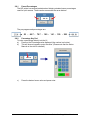
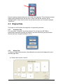
2.12 Stop / Reset
This button has two functions.
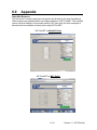
1) Press the Stop button to stop the current scan. The original
will be ejected automatically. If not, open Top Cover to
remove the original.
2) Press the Reset button to restore the “default settings” in
Copy Mode. Some of the default settings are determined in
the Information / Help Screen of the UI. (see Copy Mode
Configurations chapter)
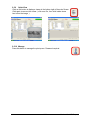
2.13 Interrupt
Network printing can be interrupted between collated sets of
documents. Press the Interrupt button to pause the queue and
allow a more urgent file to be copied. For example if a file is
needed right away and there is a job in the queue that has 20
sheets and 10 sets are being printed this can be interrupted
when one of the sets finishes printing. After the urgent file is
printed the sets will continue to print.
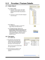
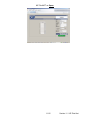
2.14 Rescan
This button only appears when “Set Copy” mode in enabled. It
allows a user to rescan an original in a set as required. This
may be due to skew or incorrect image quality settings of the
previous scan.
2.15 Log Off
This button only appears when “Accounting” functions are
enabled. This allows the current user to cease all KIP printer
functions after the user has preformed the required copies.
(after the code was entered to enable Coping)
Please note that the KIP printer will also automatically logoff
from the current user after 180 seconds of no copy function
activities by a user.
2-28
Section 2
Copy Mode - Monochrome
Section 3
Copy Mode - Color
1.0
Copy Mode – Color ............................................................................................................3- 2
1.1
Main Screen - General .........................................................................................................31.2
Simple Copying ....................................................................................................................31.2.1 Select Copy Mode............................................................................................................31.2.2 Select Size Mode .............................................................................................................31.2.3 Select Original Image Type..............................................................................................31.2.4 Print Quality......................................................................................................................31.2.5 Copy Count ......................................................................................................................31.2.6 Original Size.....................................................................................................................31.2.7 Size ..................................................................................................................................31.2.8 Insert Original...................................................................................................................32.0
2
3
3
3
4
4
5
5
6
6
Operation Details ...............................................................................................................3- 7
2.1
Main Screen .........................................................................................................................3- 7
2.2
Original.................................................................................................................................3- 7
2.2.1 Original Size Mode...........................................................................................................3- 7
2.2.2 Original Type....................................................................................................................3- 8
2.3
Print Quality .........................................................................................................................3- 8
2.3.1 Line / Graphic Mode.........................................................................................................3- 8
2.3.2 Draft / Normal / High Quaility ...........................................................................................3- 8
2.4
Copy Count ..........................................................................................................................3- 9
2.4.1 Arrows - Count Increase / Decrease ...............................................................................3- 9
2.4.2 Number Pad - Count Increase / Decrease .......................................................................3- 9
2.4.3 Set Copy ..........................................................................................................................3-10
2.4.4 Clear.................................................................................................................................3-10
2.5
Advanced Settings ...............................................................................................................3-10
2.5.1 Mirror................................................................................................................................3-10
2.5.2 Invert ................................................................................................................................3-10
2.5.3 Leading Edge Adjustment ................................................................................................3-11
2.5.4 Trailing Edge Adjustment .................................................................................................3-12
2.6
Original Size.........................................................................................................................3-13
2.6.1 Auto..................................................................................................................................3-13
2.6.2 Manual .............................................................................................................................3-13
2.6.3 Custom.............................................................................................................................3-14
2.6.4 Rotation............................................................................................................................3-15
2.7
Size – Zoom .........................................................................................................................3-15
2.7.1 Preset Percentages..........................................................................................................3-15
2.7.2.
Percentage Key Pad ....................................................................................................3-16
2.7.3.
Page Size Zoom...........................................................................................................3-16
2.7.4.
Clear.............................................................................................................................3-17
2.8.
Start .....................................................................................................................................3-18
2.9.
View Last ............................................................................................................................3-18
2.10. Recall Job ...........................................................................................................................3-18
2.11. Stop / Reset .........................................................................................................................3-18
2.12. Interrupt...............................................................................................................................3-18
2.13. Rescan ................................................................................................................................3-18
2.14. Log Off ................................................................................................................................3-18
3-1
Section 3
Copy Mode – Color
1. 0
Copy Mode - Color
1.1 Main Screen - General
3
4
5
6
1
7
2
8
9
10
11
12
No.
1
2
3
Name
Mode
Original Size
Original Type
4
Print Quality
5
6
Copy Count
Advanced Settings
7
Reset
8
9
View Last
Recall Job
10
11
12
Interrupt
Zoom
Log Off
Function
Select Color Mode from Mono Mode
Select the size of the original in length and rotation
User Selects the type of original to copy. Also select
Eng/Arch Modes here.
Select the calibrated Quality (must be calibrated prior to
use)
Select the quantity of prints and sets designation.
Invert , mirror, stamps, folds, and edge adjustments
preformed / displayed in this button (sub screen)
Clears the image buffer and resets the system to default
settings.
The last scan / job can be viewed
Images can be recalled from the last job for reprint.
Please note that a time limit may be set to recall or this
feature may be disabled by the administrator to prevent
any unauthorized copies.
Pauses the network print jobs to print any copy jobs
Manual and automatic zoom ratios set.
Displayed if Accounting enabled to Log off current user
3-2
Section 3
Copy Mode – Color
1.2 Simple Copying
To copy, please follow these basic steps. The following chapters have details on adjustments
and parameters that the user can change to modify the copies as required.
Please note that a third party color printer, supported by KIP, must first be calibrated in
the “?” screen under the “Color Config” button. Please see the “?” Section.
1.2.1 Select Copy Mode
On the lower region of the Operator Panel select “COPY” and then press the Color button if
not already selected.
1.2.2 Select Size Mode
Select whether the document is an engineering or architectural size document. This will
allow the automatic width detection to function.
Engineering widths = 34, 22, 17, 11, and 8.5 inches
Architecture widths = 36, 30, 24, 18, 12, and 9 inches
3-3
Section 3
Copy Mode – Color
1.2.3 Select Original Image Type - Input
Set the original image type you will copy. The selections are:
Line
- used for simple color line documents
Line / Photo - used for a combination of lines & photos color documents
Photo
- used for color photographic originals
This will allow automatic image quality adjustments for the scan.
1.2.4 Print Quality - Output
The model of third party color printer will determine on the available Print Quality. Select
“Graphics” or “Line Art” mode and then select “Draft, Normal or High Quality” mode for the
printer.
Please note that each Print Quality mode must be calibrated prior to its use. Please see
Color Calibration in the “?” screen for greater details.
3-4
Section 3
Copy Mode – Color
1.2.5 Copy Count
Press the arrow buttons to scroll through the number of copies required or press on the
actual number to set the quantity with the number pad.
1.2.6 Original Size
This selects automatic (for best possible fit) or manual page size selection.
or
3-5
Section 3
Copy Mode – Color
1.2.7 Size
Select
a) AutoZoom to automatically zoom to the width of paper or
b) Press the arrow keys to scroll through presets ratios or
c) Press on the Zoom number to enter a ratio on the key pad
1.2.8
Insert Original
Using the guides on the feed table, center the original face up and push forward until the
KIP 3000 accepts it.
The KIP 3000 will automatically commence to copy. While this occurs the image will be
displayed on the Operator Panel for your reference.
3-6
Section 3
Copy Mode – Color
2. 0
Operation Details
2.1 Main Screen
The main Copy Color screen is selected with the Copy Button in the lower bar, then use the
Mono / Color button in the upper left corner to select Color Mode.
The following pages detail the functions and settings of each button and sub screen that can
be used to adjust the color copy mode.
2.2 Original
This region allows the setting of the Size Mode (Engineering or Architectural) and the original
image type.
2.2.1 Original Size Mode
This button is used to select the Size Mode of Engineering or Architectural.
This will allow the automatic width detection system to determine the image width when an
original is placed in the KIP 3000.
Engineering widths = 34, 22, 17, 11, and 8.5 inches
Architectural widths = 36, 30, 24, 18, 12, and 9 inches
3-7
Section 3
Copy Mode – Color
2.2.2 Original Type - Input
Select one of the three different predetermined original types. The selections are:
a) Line
- used for simple color line documents
b) Line / Photo - used for a combination of color lines & photos
c) Photo
- used for color photographic originals
Press the desired original setting from one of the three diagrams. This will allow automatic
image quality adjustments for the scan. Please note that the selection will be highlighted
with a “black circle” and the icon will become white, as in the above example “Line/Photo”.
2.3 Print Quality - Output
This region is used to change the image quality settings on the third party printer.
2.3.1 Line / Graphic Mode
The device you will copy to will determine the best setting. Each Quality mode has three
sub modes. Each mode must be calibrated prior to use. Please see Color Calibration in the
“?” screen.
2.3.2 Draft / Normal / High Quaility
This controls the settings of the printer and which mode of image
quality will be used on the printer. Please see third party printer guide
for details.
3-8
Section 3
Copy Mode – Color
2.4 Copy Count
In this region the number of copies, and set copy / collation can be set.
2.4.1 Arrows - Count Increase / Decrease
Use the arrows to increase or decrease the total numbers of copies desired by one with
each press of the button.
In this example the arrow was press five times to reach “6 copies”.
2.4.2 Number Pad - Count Increase / Decrease
Press the “number of copies” value (which is a button) to set the desired number of copies
using a number pad. This will allow the quick entry of larger numbers.
a) Press the numbers for the quantity desired.
(up to 999)
b) Select “Enter”.
c) If an entry error was made press “C” to
start again.
d) If you wish to close the screen without
changing the quantity press “Cancel”.
3-9
Section 3
Copy Mode – Color
2.4.3 Set Copy
Has no function in Color Copy Mode.
2.4.4 Clear
Press the “eraser” button to reset the quantity to “1”.
2.5 Advanced Settings
The Advanced Setting button contains the additional
parameters on a sub screen:
a) Mirror
b) Invert
c) Lead Edge Adjustment
d) Trail Edge Adjustment
When any of the adjustments / selections is selected, the
selections will now be displayed on the main Copy
screen.
2.5.1 Mirror
Select this button to “mirror” a scan. This can be utilized on originals that
have the actual image on the reverse side such as older “sepia” or “film”
documents.
2.5.2 Invert
Select this button to change a region of white to black and visa versa of a
scanned document. This is normally used for “negative” documents or
“blue prints”.
3-10
Section 3
Copy Mode – Color
2.5.3 Leading Edge Adjustment
The leading edge of a copy can be altered. ( +/- 4” )
a) additional void area can be placed on the lead edge of a scan or
b) image can be removed (such as a binding strip or a file hanger)
Leading Edge
Leading Edge -
KIP
Image
KIP
Image
KIP
Scanner
Image
Original
Scanner
Scanner
Scan
Image
Scanner
Scan
Original
Deleted image
Added margin
To adjust the Leading Edge, use the arrows to denote the quantity you wish to add or
remove.
Touch the value displayed area to reset the quantity.
3-11
Section 3
Copy Mode – Color
2.5.4 Trailing Edge Adjustment
The trailing edge of each copy can be altered. ( +/- 4” )
a) Additional void area can be placed on the bottom of a copy or
b) Image can be removed (such as a binding strip or a file hanger)
Trail
edge +
KIP
KIP
Image
Image
Scanner
Scanner
Trail
Edge
Cop
y
KIP
KIP
Image
Image
Scanner
Origin
al
Origin
al
Cop
y
Deleted trailing
image
Added trailing
margin
To adjust the Trailing Edge, use the arrows to denote the quantity you wish to add or
remove.
Touch the value displayed area to reset the quantity.
Make any of the required adjustments / selections and press “OK” to accept. The selections
will now be displayed on the main Scan screen.
3-12
Section 3
Copy Mode – Color
2.6 Original Size
This region allows automatic or manual roll detection of the original.
2.6.1 Auto
This default setting allows the KIP 3000 to automatically detect the width and length of the
original. Please note the correct “Original Size Mode” in 2.2.1 must be select prior to the
copy.
2.6.2 Manual
To select an original size manually, select Manual and a sub screen displays all current
standard page sizes.
3-13
Section 3
Copy Mode – Color
2.6.3 Custom
This mode allows the original width and length to be determined by the number pad.
a) Set the width of the scan. Note that these are only Standard Sizes.
b) Set a Standard Length or Custom Length – set the Custom length in the key pad
and press enter.
Standard Length
Custom Length
c) The cut length will now be displayed in the Manual button. In this example 18” width and a
custom length of 25.8”.
3-14
Section 3
Copy Mode – Color
2.6.4 Rotation
Select the rotation to save copy media. This function may be void dependent on the third
party printer ability in media width and auto rotate function programmed in the printer.
Example:
D Size copy may waste less media if printed 36” wide (if the printer so supports this size
and is installed in the printer) rather than 24” wide. If the user wishes to scan the document
24” and then select a 270 degree or 90 degree rotation to print 36” width rather than 24”
this can save media.
Rotation available:
2.7 Size – Zoom
Image size / Zoom can be altered in this region of the KIP operator panel. This includes
automatic zooming, predetermined percentages, or ratio calculations to page size, and simple
percentage increments.
2.7.1 Preset Percentages
The KIP has several predetermined industry standard zoom percentages used for quick
access. These can be access with the arrow buttons.
The pre-programmed percentages are:
50 - 66.7 - 70.7 - 100 - 141 - 150 - 200
3-15
Section 3
Copy Mode – Color
2.7.2. Percentage Key Pad
To enter a percentage directly:
a) Press on the Percentage value displayed (the number is a button).
b) This will show a keypad to enter the value (please note that the button Manual on the
side is a default).
c) Press the desired zoom value and press enter.
2.7.3. Page Size Zoom
To enter a zoom percentage based on pages sizes into the UI:
a) Press on the Percentage value displayed (the number is a button). This will show a
keypad to enter the value.
3-16
Section 3
Copy Mode – Color
b) Select Standard button.
c) Select the original page size by pressing onto the
original page size button.
d) Please note either Engineering or Architectural mode
can be utilized by pressing on the button below the
original page size.
e) Select the desired Copy page size. Again please note
either Engineering or Architectural mode can be
utilized.
f) Press Enter to confirm your selections or Cancel to
restart.
2.7.4. Clear
To reset the percentage value to default, press the “erase” button.
3-17
Section 3
Copy Mode – Color
2.8.
Start
The copier is always set to “Auto Start”. When the original is inserted into
the KIP 3000 scanner, the process will begin without further user
intervention.
The start button is used when a job is recalled. The start button will “start”
the job if depressed after ‘Recall” (the name will change to “Re-print”).
2.9.
View Last
The last documented scanned to be copied be viewed.
2.10.
Recall Job
No function in Color Copy Mode.
2.11.
Stop / Reset
This button has two functions.
1) Press the Stop button to stop the current scan. The original will be
ejected automatically. If not, open Top Cover to remove the original.
2) Press the Reset button to restore the “default settings” in Copy
Mode. Some of the default settings are determined in the
Information / Help Screen of the UI. (see Copy Mode
Configurations chapter)
2.12.
Interrupt
No function in Color Copy Mode.
2.13.
Rescan
No Function in Color Copy Mode.
2.14.
Log Off
This button only appears when “Accounting” functions are enabled. This
allows the current user to cease all KIP functions after the user has
preformed the required copies (after the code was entered to enable
Coping).
Please note that the KIP printer will also automatically log off the current user after 180
seconds of no copy function activities by a user.
3-18
Section 3
Copy Mode – Color
Section 4
Scan Mode - Monochrome
1. 0
Scan Mode - Monochrome ............................................................................................. 4- 2
1.1
Main Screen ................................................................................................................. 41.2
Simple Scanning .......................................................................................................... 41.2.1 Select Scan Mode .................................................................................................... 41.2.2 Select Size Mode ..................................................................................................... 41.2.3 Select Original Image Type ...................................................................................... 41.2.4 Select Format ........................................................................................................... 41.2.5 Select Mailbox .......................................................................................................... 41.2.6 Insert Original ........................................................................................................... 41.2.7 Retrieve the File ....................................................................................................... 42. 0
2
3
3
3
4
5
6
6
6
Operation Details ............................................................................................................ 4- 7
2.1
Main Screen ................................................................................................................. 4- 7
2.2
Original......................................................................................................................... 4- 7
2.2.1 Original Size Mode ................................................................................................... 4- 7
2.2.2 Original Type ............................................................................................................ 4- 8
2.3
Original Size ................................................................................................................. 4- 8
2.3.1 Automatic Size ......................................................................................................... 4- 8
2.3.2 Manual Size.............................................................................................................. 4- 9
2.3.3 Hard Drive Space Monitor ........................................................................................ 4-10
2.3.4 Rotation .................................................................................................................... 4-11
2.4
Quality .......................................................................................................................... 4-11
2.4.1 Automatic ................................................................................................................. 4-11
2.4.2 Threshold ................................................................................................................. 4-11
2.4.3 Density ..................................................................................................................... 4-12
2.4.4 Sharpness ................................................................................................................ 4-12
2.4.5 Dither........................................................................................................................ 4-12
2.5
DPI ............................................................................................................................... 4-12
2.6
Format.......................................................................................................................... 4-13
2.7
Advanced Settings ....................................................................................................... 4-14
2.7.1 Mirror ........................................................................................................................ 4-14
2.7.2 Invert ........................................................................................................................ 4-14
2.7.3 Stamp ....................................................................................................................... 4-15
2.7.4 Leading Edge Adjustment ........................................................................................ 4-16
2.7.5 Trailing Edge Adjustment ......................................................................................... 4-17
2.8
Mailbox......................................................................................................................... 4-18
2.8.1 Selecting a Mailbox .................................................................................................. 4-18
2.8.2 Removing a Mailbox................................................................................................. 4-18
2.8.3 Creating a New Mailbox ........................................................................................... 4-19
2.8.4 SMB Setup ............................................................................................................... 4-20
2.8.4.1 Share Setup – Workstation/Server ...................................................................... 4-20
2.8.4.2 Network Location (SMB/CIFS) – IPS Setup ........................................................ 4-21
2.8.4.3 FTP Site............................................................................................................... 4-24
2.9
Start.............................................................................................................................. 4-26
2.10 Reset / Stop ................................................................................................................. 4-26
2.11 Re-Scan ....................................................................................................................... 4-26
2.12 View Last...................................................................................................................... 4-26
2.13 Log Off ......................................................................................................................... 4-26
4-1
Section 4
Scan Mode - Monochrome
1. 0
Scan Mode - Monochrome
1.1 Main Screen
4
5
6
3
7
8
9
2
10
11
1
No.
1 Mode
Name
2
Original Size
3
Original Type
4
5
6
Quality
DPI
Format
7
Advanced Settings
8
Reset / Stop
9
Mailbox
10
11
View Last
Rescan
Function
Selects the “Mode” of the system. (Scan Mode for
this screen shown)
Use automatic settings or manually set width, length
and rotation of the images.
User Selects the type of original to scan. Also select
either Eng/Arch Mode here.
Select Auto or Manual image adjustments
Scroll through final image resolution. (DPI)
Scroll through formats the scanned file will be saved
to.
Invert, mirror, stamps, and edge adjustments
preformed / displayed in this button (sub screen)
Resets the system to default settings. Stops a scan
in process
Select where the image will be stored after the scan
(KIP printer, FTP, LAN PC etc).
View the last scanned image
Rescans the last image (replaces)
4-2
Section 4
Scan Mode - Monochrome
1.2 Simple Scanning
To scan to file, please follow these basic steps.
The following chapters have details on adjustments and parameters that the user can
change to modify the scans.
1.2.1 Select Scan Mode
On the lower region of the UI, select “SCAN”.
1.2.2 Select Size Mode
Select whether the document is an engineering or architectural size document. This will
allow the automatic width detection to function.
Engineering widths = 34, 22, 17, 11, and 8.5 inches
Architecture widths = 36, 30, 24, 18, 12, and 9 inches
4-3
Section 4
Scan Mode - Monochrome
1.2.3 Select Original Image Type
Set the Original Image type you will scan. The selections are:
Line
Line / Photo
Grayscale
Photo
- used for simple line documents
- used for a combination of lines & photos documents
- used for a combination of lines & areas of shade (CAD) originals
- used for photographic originals
This will allow automatic image quality adjustments for the scan.
4-4
Section 4
Scan Mode - Monochrome
1.2.4 Select Format
Press the button to scroll through the file formats available.
TIF-G4
TLC
CAL-G4
PDF
DWF
Multipage TIF-G4
Multipage PDF
Multipage DWF
- tif format Group 4 level compressed
- KIP format compressed
- Cals Group 4 level
- PDF Level 3
- Design Web Format (AutoCAD)
- Tif format Group 4 level compressed
- PDF Level 3
- Design Web Format (AutoCAD)
Select the type you require which will save the file in this format.
4-5
Section 4
Scan Mode - Monochrome
1.2.5 Select Mailbox
Select the location to where the file will be saved. Use the “Page Arrows” to view other
choices currently available.
NOTE
The Mailboxes are predetermined by the system administrator or key operator.
Please contact these persons for any additional locations that you may require. The
“Mailbox” button will allow for additional location entries.
1.2.6 Insert Original
Using the guides on the feed table, center the original face up and push forward until the
KIP 3000 accepts it.
The KIP 3000 will automatically commence to scan. While this occurs the image will be
displayed on the Operator Panel for your reference.
1.2.7 Retrieve the File
Depending on the “Mailbox” you may now access your scan from a PC connected to the
LAN. This includes:
a) from a FTP site (using Microsoft Windows Internet Explorer or other FTP
software)
b) from the “KIP IPS Mailbox” utilizing “KIP Request” to access the document.
c) from SMB location on a remote network server or workstation
Please see the User Guides of these applications for details on their function.
4-6
Section 4
Scan Mode - Monochrome
2. 0
Operation Details
2.1 Main Screen
The main SCAN screen is selected with the Scan Button.
This screen contains all user functions for scanning to file. The following pages detail the
functions and settings of each button and sub screen that can be used to adjust the scan
parameters to achieve the required result.
2.2 Original
This region allows the setting of the Size Mode (Engineering or Architectural) and the
Original Document type.
2.2.1
Original Size Mode
This button is used to select the Size Mode of Engineering or Architectural and Original
Image type.
This will allow the automatic width detection system to determine the image width when an
original is placed in the KIP 3000.
(Eng) Engineering widths = 34, 22, 17, 11, and 8.5 inches
(Arch) Architecture widths = 36, 30, 24, 18, 12, and 9 inches
4-7
Section 4
Scan Mode - Monochrome
2.2.2
Original Type
Select one of the four different predetermined original types. The selections are:
a) Line
b) Line / Photo
c) Grayscale
d) Photo
- used for simple line documents
- used for a combination of lines & photos documents
- used for a combination of lines & areas of shade (CAD)
originals
- used for photographic originals
Press the desired original setting from one of the four diagrams. This will allow automatic
image quality adjustments for the next scan. Please note that the selection will be
highlighted with a “black” circle and the icon will become white, as in the above example
“Grayscale”.
2.3 Original Size
This region is used to select the image size of the original being scanned.
2.3.1
Automatic Size
For most scans, “Automatic” should be selected. This will allow the KIP 3000 to
automatically determine the width and length of the scan without any user intervention.
(Please also note “Original Size Mode” in 2.2)
4-8
Section 4
Scan Mode - Monochrome
2.3.2
Manual Size
To select an original size manually, select Manual and a sub screen displays all current
standard page sizes.
a) Select a desired size of the sheet.
b) Or use “Custom” to select a width.
c) Set a standard size width.
4-9
Section 4
Scan Mode - Monochrome
d) Select a standard size length or
e) Select a custom length with the key pad.
f) Press “Reset” to begin again,
“Enter” to accept the settings or Cancel” to
cancel “Manual” image size.
g) The main Scan screen will now
display the custom or manual size
settings for the next image.
2.3.3
Hard Drive Space Monitor
Located on the main screen of the KIP printer Scan mode, the Disk Use
monitor provides a real-time display of remaining disk space on the KIP
printer’s hard drive. The monitor shows both the used space and the space
available for image storage on the drive.
4-10
Section 4
Scan Mode - Monochrome
2.3.4
Rotation
The file can be saved rotated, from the actual feed direction. This can be used to reduce
the scan time on certain orientation of originals, when they are archived.
Press the “Rotation” button to select either one of four settings:
2.4 Quality
This region is used to change the image quality settings from the
automatic setting.
2.4.1
Automatic
For most scans, “Auto” should be selected. This will allow the KIP
3000 to automatically determine the best image settings without any
user intervention. (Please also note “Original” in 2.2)
2.4.2
Threshold
To override the “Automatic” settings, “Threshold” can be adjusted.
Deselect “Auto” to enable “Threshold”.
Pressing the arrows manually adjusts the threshold. This will
suppress or enhance the lines and images from the original.
4-11
Section 4
Scan Mode - Monochrome
2.4.3
Density
To override the “Automatic” settings, “Density” can be adjusted.
Deselect “Auto” to enable “Density”.
Pressing the arrows manually adjusts the background density. This
will suppress or enhance the background from the original.
2.4.4
Sharpness
To override the “Automatic” settings, “Sharpness” can be adjusted.
Deselect “Auto” to enable “Sharpness”.
Pressing the arrows manually adjusts the line sharpness to remove
rough lines or when photos are scanned to allow for smoother
graduations.
2.4.5
Dither
To override the “Automatic” settings, “Dither” can be adjusted.
Deselect “Auto” to enable “Dither”.
By pressing the dither button,
a) None
b) Fine
c) Medium or
d) Course
This will change how the dots are arranged to create the final image
of the scan. For fine lines a “Course” dither pattern may be desired.
For Photos “None” may be desired.
2.5 DPI
Scroll through the DPI button to select the required scan resolution.
Choices are 200, 300, 400 or 600 DPI.
300
400
4-12
Section 4
Scan Mode - Monochrome
2.6 Format
Press the “Format” button to toggle through the file formats available.
TIF-G4
- tif format Group 4 level compressed
TLC
- KIP format compressed
CAL-G4
- Cals Group 4 level
PDF
- PDF Level 3
DWF
- Design Web Format (AutoCAD)
Multipage TIF-G4 - Tif format Group 4 level compressed
Multipage PDF
- PDF Level 3
Multipage DWF
- Design Web Format (AutoCAD)
Select the file type required to save the image into this format.
TLC
Cals
For a Multipage scan, select the desired Multipage format. Start button will prompt for next
original.
When finished scanning, select the Close File button to finalize the multipage file.
4-13
Section 4
Scan Mode - Monochrome
2.7 Advanced Settings
The Advanced Setting button contains the additional parameters on a sub screen:
a) Invert
b) Mirror
c) Stamp (Water Mark)
d) Lead Edge Adjustment
e) Trail Edge Adjustment
Make any required adjustments / selections and press “OK” to accept. The selections will
now be displayed on the main Scan screen.
2.7.1
Mirror
Select this button to “mirror” a scan. This can be utilized on originals that
have the actual image on the reverse side such as older “sepia” or “film”
documents.
2.7.2
Invert
Select this button to change a region of white to black and visa versa of a
scanned document. This is normally used for “negative” documents or
“blue prints”.
4-14
Section 4
Scan Mode - Monochrome
2.7.3
Stamp
Select “Stamp” to display another sub screen. This will allow the selection of a “Stamp” or
“Water Mark” to be placed on the scanned image. It will be embedded digitally into the
image.
a) Use the Arrow buttons to scroll
through the available stamps and
then select the stamp from the list.
b) The Stamp button will now display the stamp
selected.
NOTE
The list of “Stamps” is loaded into Scan Mode by the system administrator or key
operator. They can not be altered or modified in any manner on the KIP printer’s
UI.
Please contact these persons for any additional stamps that may be required.
Please see “KIP Request” for these functions.
4-15
Section 4
Scan Mode - Monochrome
2.7.4
Leading Edge Adjustment
The leading edge of a scan can be altered. ( +/- 4” )
a) additional void area can be placed on the lead edge of a scan or
b) image can be removed (such as a binding strip or a file hanger)
Leading Edge +
Leading Edge -
KIP
Image
Scanner
Original
Image
KIP
Image
KIP
Scanner
Image
Scanner
Scanner
Original
Scan
Scan
Deleted image
Added margin
To adjust the Leading Edge, use the arrows to denote the quantity you wish to add or
remove.
Touch the value displayed area to reset the quantity.
4-16
Section 4
Scan Mode - Monochrome
2.7.5
Trailing Edge Adjustment
The trailing edge of a scan can be altered. ( +/- 4” )
c) additional void area can be placed on the bottom of a scan or
d) image can be removed (such as a binding strip or a file hanger)
Trail edge +
Trail Edge -
KIP
KIP
KIP
KIP
Image
Image
Image
Image
Scanner
Scanner
Scanner
Scan
Original
Original
Scan
Deleted trailing image
Added trailing margin
To adjust the Trailing Edge, use the arrows to denote the quantity you wish to add or
remove.
Touch the value displayed area to reset the quantity.
Make any of the required adjustments / selections and press “OK” to accept. The
selections will now be displayed on the main Scan screen.
4-17
Section 4
Scan Mode - Monochrome
2.8 Mailbox
This region of the Scan screen allows the user to select where the files will be placed.
2.8.1
Selecting a Mailbox
a) Use the arrow keys to scroll through the list as needed.
b) Select the location by pressing on it.
2.8.2
Removing a Mailbox
a) Press the “-“ button on the main Scan screen.
b) Select which “Mailbox” you wish to remove.
NOTE
The “Mailbox” removed also removes
all documents images with that folder.
ENSURE YOU HAVE BACKED UP or
DOWNLOADED ANY NECESSARY
FILES IN THE FOLDER PRIOR TO
REMOVING IT IN THE NEXT STEP!
4-18
Section 4
Scan Mode - Monochrome
c) Press “Remove”.
2.8.3
Creating a New Mailbox
a) Press the Mailbox Button.
b) The Mailbox Setup screen is displayed.
4-19
Section 4
Scan Mode - Monochrome
c) Select Mailbox Name. A screen keyboard will be displayed.
Enter the new Mailbox name.
d) Enter the new location using standard protocols of networking for scans to the:
IPS Mailbox
Set a name for the location
Examples:
Dsmith
B_Project
Team_XYZ
Michele
Access to these folders and the scanned images is preformed from the KIP
Request application. Please see the User Guide of “KIP Request” for the
retrieval function.
FTP Locations
Please contact your network administrator for details on how to configure
and load FTP locations into the KIP printer Scan Mode. (Administrator /
Service Functions of the KIP printer) Please see your network administrator
for access to your FTP and the retrieval of the documents from the FTP.
2.8.4
2.8.4.1
SMB Setup
Share Setup – Workstation/Server
When setting up a share at a workstation or server, it is necessary to have
some information ahead of time.
• User must have rights to share a folder
• User must know where the access rights are held
o Rights are local to the PC or Domain (Active Directory)
• File and Print Sharing must be enabled within the Windows XP firewall
settings
• User must be able to read, write and modify the destination SMB
folder
• User must know login username and password
4-20
Section 4
Scan Mode - Monochrome
2.8.4.2
Network Location (SMB/CIFS) – IPS Setup
Server Message Block/Common Internet File System (SMB/CIFS) allows the user to create a
semi-permanent connection to a network resource for scan to file.
Function Button
Mailbox Name
Destination
Server/Workstation
Domain
Share Path
Username
Password
Test SMB
Description
Descriptor to be displayed on SCAN screen (Preceded by SMB:)
This will turn green when connected
IP address or NetBIOS name of destination workstation/server
Name of authorization provider (Domain server or workgroup
workstation)
Shared resource on destination workstation/server
Login credentials on destination workstation/server
Password for supplied username on destination
workstation/server
Maps a network drive to the destination workstation/server
Within the SCAN screen, press the Mailbox button to create an SMB connection.
a) Touch the SMB button to display the SMB Mailbox creation dialog.
b) Press the Mailbox Name button to enter a descriptive name for the SMB scan to file
location. This description will be displayed on the SCAN screen with the label of SMB:
[Mailbox Name].
c) Touch Destination Server/Workstation button to enter the NetBIOS name or IP address
of the destination server or workstation that the KIP IPS will connect to in order to allow for
scan to file.
a. This must be a server or workstation that the KIP IPS has access to via TCP/IP.
b. Please ensure that the KIP printer has been networked properly and is “pingable”
from the destination server/workstation.
4-21
Section 4
Scan Mode - Monochrome
d) Touch Domain button to enter the client authorization information. This entry will work in
conjunction with the Username/Password entries as defined in later steps.
c. Some facilities will have user credentials (SAM) stored on a central authorization
server (Domain Controller/Active Directory Server) that will grant connection access
to the KIP IPS for shared resources. If the KIP IPS is connecting to a workstation
(WS01) that is a part of the Acme.com domain, then the user would enter Acme in
the Domain section. The KIP IPS would get authorization credentials from the
SVR01 server in order to scan to the “Scans” folder on the WS01 workstation
(SSmith’s PC).
4-22
Section 4
Scan Mode - Monochrome
d. If the KIP IPS is in a workgroup setting (No Domain Controller/Active Directory
Server), the authorization credentials (SAM) will be supplied by the destination
workstation/server (WS06). If the user is connecting to a shared resource on a
workstation (Scans folder) with the NetBIOS (computer) name of WS06, the user
would input WS06 for the Domain section. The KIP IPS would get the authorization
credentials from the WS06 workstation.
e) Touch the Share Path button to enter the name of the shared folder on the destination
workstation or server.
a. The shared folder on the destination workstation must be accessible by the user as
supplied in the Username setting.
b. These permissions should include the ability to write and modify on this shared
folder.
f)
Username and Password should be set as an accessible login username from either the
workgroup workstation/server or the authentication server/domain controller.
g) Touching on Test SMB will make the KIP IPS attempt to establish a connection to the
destination workstation/server.
a. The connection is established when the SMB mailbox is selected and is
disconnected when:
i. Switching Formats
ii. Pressing the STOP button
iii. Switching menus (SCAN, COPY, JOB INFO, “?”)
iv. Selecting another mailbox
v. Creating another SMB mailbox
vi. Reset timer expiration
vii. Log off
4-23
Section 4
Scan Mode - Monochrome
It is possible to scan all file formats to an SMB location. Please note that color image data is much
larger and may take considerable network resources in order to transfer from the IPS to the SMB
location. (A full color, 600 DPI, tiff packbit can be several gigabytes in size).
When scanning multi page documents (PDF, DWF and TIFF), the images are scanned to a
temporary location on the IPS and then transferred to the SMB location once the Close File button
has been pressed.
SMB Locations
Please contact your network administrator for details on how to configure SMB locations
on the remote server or workstation.
2.8.4.3
FTP Site
To load and access FTP locations on the KIP device please follow these steps:
a) In Request, enable Advance Features by selecting the Options menu and selection
Advanced Features
b) Click Options and then select Find KIP Printers and the Add a Printer to this List.
Select Set FTP Address and enter the necessary FTP information
4-24
Section 4
Scan Mode - Monochrome
c) Send to the KIP IPS by using Transfer and then Upload Settings to Printer
d) At the KIP IPS, enter (?) and then Service. Once you are in the Service menu, (password
required) use the arrow keys at the bottom until “Import Settings” is shown (this will appear
grayed out at first) touch the button labeled Touch. This will import any new FTP settings
and will be displayed on the SCAN screen. These will be in the form FTP: [FTP
Description].
4-25
Section 4
Scan Mode - Monochrome
2.9 Start
No function at this time in Scan Mode.
All scans in Scan Mode are “Auto Start”.
2.10 Reset / Stop
This button has two functions.
1) Press the Stop button on the UI to stop the current scan. The original
will be ejected automatically. If not, open Top Cover to remove the
original.
2) Press the Reset button to restore the “default settings” in Scan Mode.
Some of the default settings are determined in the Information / Help Screen of the
UI. (see Scan Mode Configurations chapter)
2.11 Re-Scan
If the scanned image was not satisfactory, you can replace the last image
scan by selecting this button and proceeding with the scan procedure as
normal.
2.12 View Last
Allows the last scan to be reviewed again on the UI.
2.13 Log Off
This button may be displayed if accounting is enabled. Press this button to
log off the current user after scanning has been completed.
4-26
Section 4
Scan Mode - Monochrome
Section 5
Scan Mode - Color
1. 0
Scan Mode – Color.......................................................................................................... 5- 2
1.1
Main Screen ................................................................................................................. 51.2
Simple Scanning .......................................................................................................... 51.2.1 Select Scan Mode .................................................................................................... 51.2.2 Select Size Mode ..................................................................................................... 51.2.3 Select Original Image Type ...................................................................................... 51.2.4 Select Format ........................................................................................................... 51.2.5 Select Mailbox .......................................................................................................... 51.2.6 Insert Original ........................................................................................................... 51.2.7 Retrieve the File ....................................................................................................... 52. 0
2
3
3
3
3
4
4
5
5
Operation Details ............................................................................................................ 5- 6
2.1
Main Screen ................................................................................................................. 5- 6
2.2
Original......................................................................................................................... 5- 6
2.2.1 Original Size Mode ................................................................................................... 5- 6
2.2.2 Original Type ............................................................................................................ 5- 6
2.3
Original Size ................................................................................................................. 5- 7
2.3.1 Automatic Size ......................................................................................................... 5- 7
2.3.2 Manual Size.............................................................................................................. 5- 7
2.3.3 Hard Drive Space Monitor ........................................................................................ 5- 8
2.3.4 Rotation .................................................................................................................... 5- 9
2.4
DPI ............................................................................................................................... 5- 9
2.5
Format.......................................................................................................................... 5- 9
2.6
Advanced Settings ....................................................................................................... 5-10
2.6.1 Mirror ........................................................................................................................ 5-10
2.6.2 Invert ........................................................................................................................ 5-10
2.6.3 Leading Edge Adjustment ........................................................................................ 5-10
2.6.4 Trailing Edge Adjustment ......................................................................................... 5-11
2.7
Mailbox......................................................................................................................... 5-12
2.7.2 Removing a Mailbox................................................................................................. 5-12
2.7.3 Creating a New Mailbox ........................................................................................... 5-13
2.7.4 SMB Setup ............................................................................................................... 5-14
2.7.4.1 Share Setup – Workstation/Server .................................................................... 5-14
2.7.4.2 Network Location (SMB/CIFS) – IPS Setup ...................................................... 5-15
2.7.4.3 FTP Site............................................................................................................. 5-18
2.8
Start.............................................................................................................................. 5-20
2.9
Reset / Stop ................................................................................................................. 5-20
2.10 Re-Scan ....................................................................................................................... 5-20
2.11
View Last..................................................................................................................... 5-20
2.12 Log Off ......................................................................................................................... 5-20
5-1
Section 5
Scan Mode - Color
1. 0
Scan Mode – Color
1.1 Main Screen
3
5
6
4
7
1
8
9
10
2
11
No.
Name
1 Mode
2 Original Size
3
Original Type
4
5
6
Quality
DPI
Format
7
Advanced Settings
8
Reset / Stop
9
Mailbox
10
11
View Last
Rescan
Function
Selects “Color Mode” while in Scan mode
Use automatic settings or manually set width, length
and rotation of the image.
User Selects the type of original to scan. Also select
either Eng/Arch Mode here.
Select the original image type to be scanned - Input
Scroll through the image resolution. (DPI)
Scroll through formats the file will be saved to output
Invert, mirror, and edge adjustments preformed /
displayed with this button (sub screen)
Resets the system to default settings. Stops a scan
in process
Select where the image will be stored after the scan
(KIP Mailbox, FTP, SMB)
View the last scanned image
Rescans the last image (replaces)
5-2
Section 5
Scan Mode - Color
1.2 Simple Scanning
To scan to file in color, please follow these basic steps. The following chapters have
details on adjustments and parameters that the user can change to modify color scans.
1.2.1 Select Scan Mode
On the lower region of the UI, select “SCAN” then select Color Mode in the upper left
corner.
1.2.2 Select Size Mode
Select whether the document is an engineering or architectural size document. This will
allow the automatic width detection to function.
Engineering widths = 34, 22, 17, 11, and 8.5 inches
Architecture widths = 36, 30, 24, 18, 12, and 9 inches
1.2.3 Select Original Image Type
Set the original Image type you will scan. The selections are:
Line
- used for simple color line documents
Line / Photo - used for a combination of color lines & photos
Photo
- used for color photographic originals
5-3
Section 5
Scan Mode - Color
This will allow automatic image quality adjustments for the color scan.
1.2.4 Select Format
Press the button to scroll through the
file formats available.
TIF Packbit
JPEG
PDF Color
Select a desired file format.
1.2.5 Select Mailbox
Select the location to where the file will
be saved. Use the “Page Arrows” to
view other choices currently available.
NOTE
The Mailboxes are predetermined by the system administrator or key operator.
Please contact these persons for any additional locations that you may require. The
“Mailbox” button will allow for additional location entries.
5-4
Section 5
Scan Mode - Color
1.2.6 Insert Original
Using the guides on the feed table, center the original face up and push forward until the
KIP 3000 accepts it.
The KIP 3000 will automatically commence to scan. While this occurs the image will be
displayed on the Operator Panel for your reference.
1.2.7 Retrieve the File
Depending on the “Mailbox” you may now access your scan from a PC connected to the
LAN. This includes:
a) from a FTP site (using Microsoft Windows Internet Explorer or other FTP
software)
b) from the “KIP IPS Mailbox” utilizing “KIP Request” to access the document.
c) from SMB Location on remote server or workstation
Please see the User Guides of these applications for details on their function.
5-5
Section 5
Scan Mode - Color
2. 0
Operation Details
2.1 Main Screen
On the lower region of the UI, select “SCAN” then select Color Mode in the upper left
corner.
This screen contains all user functions for scanning to file in color. The following pages
details the functions and settings of each button and sub screens that can be used to
adjust the scan parameters to achieve the required result.
2.2 Original
This region allows the setting of the Size Mode (Engineering or Architectural) and the
Original Document type.
2.2.1
Original Size Mode
This button is used to select the Size Mode of Engineering or Architectural.
This will allow the automatic width detection system to determine the image width when an
original is placed in the KIP 3000.
Engineering widths = 34, 22, 17, 11, and 8.5 inches
Architectural widths = 36, 30, 24, 18, 12, and 9 inches
2.2.2
Original Type
Select one of the three different predetermined original types. The selections are:
a) Line
b) Line / Photo
c) Photo
- used for simple color line documents
- used for a combination of color lines & photos
- used for color photographic originals
5-6
Section 5
Scan Mode - Color
Press the desired original setting from one of the three diagrams. This will allow automatic
image quality adjustments for the next scan. Please note that the selection will be
highlighted with a “black circle” and the icon will become white, as in the above example
“Line/Photo”.
2.3 Original Size
This region is used to select the image size of original being scanned.
2.3.1
Automatic Size
For most scans, “Automatic” should be selected. This will allow the KIP 3000 to
automatically determine the width and length of the scan without any user intervention.
(Please also note “Original Size Mode” in 2.2.)
2.3.2
Manual Size
To select an original size manually, select Manual and a sub screen displays all current
standard page sizes.
a) Select a size or press “custom”.
5-7
Section 5
Scan Mode - Color
b) Or use Custom to select a width.
c) Set the width of the scan. Note that these are only Standard Sizes.
d) Set a Standard Length or Custom Length – set the Custom length in the key pad
and press enter.
Standard Length
Custom Length
e) The cut length will now be displayed in the Manual button. In this example 18” width
and a custom length of 25.8”.
2.3.3
Hard Drive Space Monitor
Located on the main screen of the KIP printer Scan mode, the Disk Use
monitor provides a real-time display of remaining disk space on the KIP
printer’s hard drive. The monitor shows both the used space and the space
available for image storage on the drive.
5-8
Section 5
Scan Mode - Color
2.3.4
Rotation
The file can be saved rotated from the actual feed direction. This can be used to reduce
the scan time on certain orientation of originals, when they are archived.
Press the “Rotation” button to select either one of four settings:
2.4 DPI
Scroll through the DPI button to select the required scan resolution.
Choices are 200, 300, 400 or 600 DPI.
300
400
2.5 Format
Press the “Format” button to scroll through the file formats available.
TIF Packbit
JPEG
PDF Color
Select the file type required to save the image into this format.
5-9
Section 5
Scan Mode - Color
2.6 Advanced Settings
The Advanced Setting button contains the additional parameters on a sub screen:
a)
b)
c)
d)
Mirror
Invert
Lead Edge Adjustment
Trail Edge Adjustment
When any of the adjustments / selections is selected, the selections will now be displayed
on the main Scan screen.
2.6.1 Mirror
Select this button to “mirror” a scan. This can be utilized on originals that
have the actual image on the reverse side such as older “sepia” or “film”
documents.
2.6.2 Invert
Select this button to change a region of white to black and visa versa of a
scanned document. This is normally used for “negative” documents or
“blue prints”.
2.6.3 Leading Edge Adjustment
The leading edge of a scan can be altered. ( +/- 4” )
a) additional void area can be placed on the lead edge of a scan or
b) image can be removed (such as a binding strip or a file hanger)
Leading Edge +
Leading Edge -
KIP
Image
KIP
Image
KIP
Scanner
Image
Original
Scanner
Scanner
Image
Scanner
Scan
Original
Scan
Deleted image
Added margin
5-10
Section 5
Scan Mode - Color
To adjust the Leading Edge, use the arrows to denote the quantity you wish to add or
remove.
Touch the value displayed area to reset the quantity.
2.6.4 Trailing Edge Adjustment
The trailing edge of each scan can be altered. ( +/- 4” )
c) additional void area can be placed on the bottom of a scan or
d) image can be removed (such as a binding strip or a file hanger)
Trail edge +
Trail Edge -
KIP
KIP
KIP
KIP
Image
Image
Image
Image
Scanner
Scanner
Scanner
Scan
Original
Original
Scan
Deleted trailing image
Added trailing margin
To adjust the Trailing Edge, use the arrows to denote the quantity you wish to add or
remove.
Touch the value displayed area to reset the quantity.
Make any of the required adjustments / selections and press “OK” to accept. The
selections will now be displayed on the main Scan screen.
5-11
Section 5
Scan Mode - Color
2.7 Mailbox
This region of the Scan screen allows the user to select where the color files will be placed.
2.7.1
Selecting a Mailbox
a) Use the arrow keys to scroll through the list as needed.
b) Select the location by pressing on it.
2.7.2
Removing a Mailbox
a) Press the “-“ button on the main Scan screen.
b) Select which “Mailbox” you wish to remove.
NOTE
The “Mailbox” removed also removes
all documents images with that folder.
ENSURE YOU HAVE BACKED UP or
DOWNLOADED ANY NECESSARY
FILES IN THE FOLDER PRIOR TO
REMOVING IT IN THE NEXT STEP!
5-12
Section 5
Scan Mode - Color
c) Press “Remove”.
2.7.3
Creating a New Mailbox
a) Press the Mailbox Button.
b) The Mailbox Setup screen is displayed.
5-13
Section 5
Scan Mode - Color
c) Select Mailbox Name. A screen keyboard will be displayed.
Enter the new Mailbox name.
d) Enter the new location using standard protocols of networking for scans to the:
IPS Mailbox
Set a name for the location
Examples:
Dsmith
B_Project
Team_XYZ
Michele
Access to these folders and the scanned images is preformed from the KIP
Request application. Please see the User Guide of “KIP Request” for the
retrieval function.
FTP Locations
Please contact your network administrator for details on how to configure
and load FTP locations into the KIP printer Scan Mode. ( Administrator /
Service Functions of the KIP printer ) Please see your network administrator
for access to your FTP and the retrieval of the documents from the FTP.
2.7.4
SMB Setup
2.7.4.1
Share Setup – Workstation/Server
When setting up a share at a workstation or server, it is necessary to have
some information ahead of time.
• User must have rights to share a folder
• User must know where the access rights are held
o Rights are local to the PC or Domain (Active Directory)
• File and Print Sharing must be enabled within the Windows XP firewall
settings
• User must be able to read, write and modify the destination SMB
folder
• User must know login username and password
5-14
Section 5
Scan Mode - Color
2.7.4.2
Network Location (SMB/CIFS) – IPS Setup
Server Message Block/Common Internet File System (SMB/CIFS) allows the user to create a
semi-permanent connection to a network resource for scan to file.
Function Button
Mailbox Name
Destination
Server/Workstation
Domain
Share Path
Username
Password
Test SMB
Description
Descriptor to be displayed on SCAN screen (Preceded by SMB:)
This will turn green when connected
IP address or NetBIOS name of destination workstation/server
Name of authorization provider (Domain server or workgroup
workstation)
Shared resource on destination workstation/server
Login credentials on destination workstation/server
Password for supplied username on destination
workstation/server
Maps a network drive to the destination workstation/server
Within the SCAN screen, press the Mailbox button to create an SMB connection.
a) Touch the SMB button to display the SMB Mailbox creation dialog.
b) Press the Mailbox Name button to enter a descriptive name for the SMB scan to file
location. This description will be displayed on the SCAN screen with the label of SMB:
[Mailbox Name].
c) Touch Destination Server/Workstation button to enter the NetBIOS name or IP address
of the destination server or workstation that the KIP IPS will connect to in order to allow for
scan to file.
a. This must be a server or workstation that the KIP IPS has access to via TCP/IP.
b. Please ensure that the KIP printer has been networked properly and is “pingable”
from the destination server/workstation.
d) Touch Domain button to enter the client authorization information. This entry will work in
conjunction with the Username/Password entries as defined in later steps.
5-15
Section 5
Scan Mode - Color
c. Some facilities will have user credentials stored on a central authorization server
(Domain Controller/Active Directory Server) that will grant connection access to the
KIP IPS for shared resources. If the KIP IPS is connecting to a workstation (WS01)
that is a part of the Acme.com domain, then the user would enter Acme in the
Domain section. The KIP IPS would get authorization credentials from the SVR01
server in order to scan to the “Scans” folder on the WS01 workstation (SSmith’s PC).
5-16
Section 5
Scan Mode - Color
d. If the KIP IPS is in a workgroup setting (No Domain Controller/Active Directory
Server), the authorization credentials will be supplied by the destination
workstation/server (WS06). If the user is connecting to a shared resource on a
workstation (Scans folder) with the NetBIOS (computer) name of WS06, the user
would input WS06 for the Domain section. The KIP IPS would get the authorization
credentials from the WS06 workstation.
e) Touch the Share Path button to enter the name of the shared folder on the destination
workstation or server.
a. The shared folder on the destination workstation must be accessible by the user as
supplied in the Username setting.
b. These permissions should include the ability to write and modify on this shared
folder.
f)
Username and Password should be set as an accessible login username from either the
workgroup workstation/server or the authentication server/domain controller.
g) Touching on Test SMB will make the KIP IPS attempt to establish a connection to the
destination workstation/server.
a. The connection is established when the SMB mailbox is selected and is
disconnected when:
i. Switching Formats
ii. Pressing the STOP button
iii. Switching menus (SCAN, COPY, JOB INFO, ?)
iv. Selecting another mailbox
v. Creating another SMB mailbox
vi. Reset timer expiration
vii. Log off
5-17
Section 5
Scan Mode - Color
It is possible to scan all file formats to an SMB location. Please note that color image data is much
larger and may take considerable network resources in order to transfer from the IPS to the SMB
location. (A full color, 600 DPI, tiff packbit can be several gigabytes in size).
When scanning multi page documents (PDF, DWF and TIFF), the images are scanned to a
temporary location on the IPS and then transferred to the SMB location once the Close File button
has been pressed.
SMB Locations
Please contact your network administrator for details on how to configure SMB locations
on the workstation.
2.7.4.3
FTP Site
To load and access FTP locations on the KIP device please follow these steps:
a) In Request, enable Advance Features by selecting the Options menu and selection
Advanced Features
b) Click Options and then select Find KIP Printers and the Add a Printer to this List.
Select Set FTP Address and enter the necessary FTP information
5-18
Section 5
Scan Mode - Color
c) Send to the KIP IPS by using Transfer and then Upload Settings to Printer
d) At the KIP IPS, enter (?) and then Service. Once you are in the Service menu, (password
required) use the arrow keys at the bottom until “Import Settings” is shown (this will appear
grayed out at first) touch the button labeled Touch. This will import any new FTP settings
and will be displayed on the SCAN screen. These will be in the form FTP:[FTP Description].
5-19
Section 5
Scan Mode - Color
2.8 Start
No function at this time in Scan Mode.
All scans in Scan Mode are “Auto Start”.
2.9 Reset / Stop
This button has two functions.
1) Press the Stop button to stop the current scan. The original will be
ejected automatically. If not, open Top Cover to remove the original.
2) Press the Reset button to restore the “default settings” in Scan Mode.
Some of the default settings are determined in the Information / Help
Screen of the UI. (see Scan Mode Configurations chapter)
2.10 Re-Scan
If the scanned image was not satisfactory, you can replace the last image
scan by selecting this button and proceeding with the scan procedure as
normal.
2.11 View Last
Allows the last scan to be reviewed again on the UI.
2.12 Log Off
This button may be displayed if accounting is enabled. Press this button to
log off the current user after the scanning has been completed.
5-20
Section 5
Scan Mode - Color
Section 6
Job Info Screen
1. 0
Job Info Screen
1.1 Main Screen – Summary
6- 2
6- 2
2. 0
Operation Details
2.1 Job List - Main Screen
2.2 User Name
2.3 Job – Number
2.4 Status
2.5 Type
2.6 Total
2.7 Delete
2.8 Change of Media in a Print Job
2.9 To Top
2.10 Pause
2.11 Page Scroll
2.12 Media Information
2.13 Change Media Information
2.14 Job History
6- 3
6- 3
6- 4
6- 4
6- 5
6- 5
6- 5
6- 6
6- 7
6- 8
6- 8
6- 9
6- 9
6- 10
6- 11
6-1
Section 6
Job Info Screen
1. 0
Job Info Screen
1.1 Main Screen
3
4
11
5
6
2
7
8
9
10
1
No.
1
Name
Mode
2
User Name – Job #
3
Media Information
4
5
6
Status
Type
Total
7
To Top
8
Pause
9
Delete
10
11
Up/Down
Job Info/Job History Switch
Function
Selects the “Mode” of the system. (Job Mode for this
screen shown)
Display the User and any user info for the job ID. A job
can be selected for other functions noted below.
Displays and allows change of the Width and Type.
Shows the amount remaining per roll deck. (two or four
rolls depended on system)
Shows the current status of a job and media selection.
Displays a copy or network print job
Displays the total number of prints and current number
printed.
After a job is selected (see #2) the position in the queue
can be changed to the next job printed.
Pauses printer to allow media change, etc
After a job is selected (see #2) it can be removed from
printing.
Scrolls through pages in the queue if so available.
Switches between Job Info and Job History screen if
enabled.
6-2
Section 6
Job Info Screen
2. 0
Operation Details
The Job Info screen is used to view or manage the current copy or prints jobs on the KIP
5000.
2.1 Job List - Main Screen
All jobs that are currently printing or are waiting to print are displayed in this area.
You may view a jobs details, (or for other functions described further in this manual) by
selecting the job from the list
6-3
Section 6
Job Info Screen
2.2
User Name
Displays the “Name” or the “owner” of the job
This information is obtained from fields within:
a) KIP Request
b) KIP Windows Driver
c) KIP AutoCAD Driver
d) Or from the Accounting Fields on the copier when accounting is
enabled
Please see respective User Guides for detailed information
An example screen from Request:
2.3
Job Number
Displays the “Job Number” or details regarding the job
This information is obtained from fields within:
e) KIP Request
f) KIP Windows Driver
g) KIP AutoCAD Driver
h) Or from the Accounting Fields on the copier / scanner when
accounting is enabled
An example from Copy / Scan Accounting:
6-4
Section 6
Job Info Screen
2.4
Status
Displays the current “Status” of a job.
Displays one of the following:
a) Processing – job is currently printing
b) On Hold – puts the job in the queue but will not print until
a valid media type is applied
c) Vellum – Media required - Vellum
d) Film – Media required - Film
e) Bond – Media required - Bond
2.5
Type
Displays the source of the job, jobs can be sent from the network or come from the copier
functions.
For network jobs, the following symbol is displayed:
For copy job the following symbol is displayed:
2.6
Total
Displays the number of prints, this includes:
a) the quantity in each job
b) the amount remaining , when a job is printing.
6-5
Section 6
Job Info Screen
2.7 Delete
To remove a job from the Job list:
a) Select the job to remove
Another Screen will appear.
b) Press the Delete button
c) The job will be removed from the list.
6-6
Section 6
Job Info Screen
2.8 Change Media Type in Print Job
To change the media type in a job that may be in the job list:
a) Select the job
b) Job Information screen will appear.
c) Press the Bond, Vellum
or Film button to set the
new media type for this
job.
6-7
Section 6
Job Info Screen
2.9
To Top
If a job in the list is required urgently and there are other jobs in the list prior to it, the job
can be moved to the top of the queue.
a) Select the job from the list
b) Press the “To Top” button
c) The list will be updated with urgent job to be printed next.
2.10
Pause
To pause all print jobs (to replace paper or perform another task that
may require the printer to pause) press the pause button.
6-8
Section 6
Job Info Screen
2.11 Page Scroll
Arrows may appear in the lower right corner of the screen to scroll through
the pages of jobs. Please note that the total number of pages will be
displayed as well as the current page.
2.12 Media Information
At the top of the Job List Screen is the region that displays the current media loaded in KIP
5000. Please note that only rolls the printer has will be displayed.
Amount Remaining
Type
Roll Deck Number
Width
a) Roll Deck Number
b) Amount Remaining: shows the quantity of media in ¼ steps.
Example:
Roll 1 is full
Roll 2 is ¼ full
Roll 3 is ¾ full
Roll 4 is also full
If no media installed then all bars would be empty
c) Type: Shows the media type ( set by User )
Example:
Roll 1 is Bond
Roll 4 is Vellum
d) Width: Shows the set width ( set by User )
Example: Roll 1 is 30”
Roll 2 is 36”
Roll 3 is 24”
Roll 4 is 11”
6-9
Section 6
Job Info Screen
2.13 Change Media Information
At the top of the Job List Screen is the region that displays the current media loaded in KIP
3000. Please note that only rolls the printer has will be displayed.
a) Touch any blank blue area of this region to the set media type and width in all roll
decks
b) Select the correct media width and type for each deck as required ( two roll model
screen shown below )
c) Select OK to set
d) The new settings will be noted on the top of the Job Info Screen
6-10
Section 6
Job Info Screen
2.14 Job History
KIP Job History can be used to call up and print jobs that were previously printed. By
selecting a job from the Job History list, the job can be changed and resubmitted for
printing.
1. To use the KIP Job History select the Job Info Button and click on the Current
Job button
2. The Job History Information will now be displayed on the screen and select the
job to be edited.
3. Select the Edit Button to access the available options for the current selected job.
6-11
Section 6
Job Info Screen
4. Users have the option to change Accounting information, Media type, Number of
Originals and number of sets. Or to delete the job from History.
5. When all changes (if any) are complete select the Submit button to send the job
to the printer.
6-12
Section 6
Job Info Screen
Section 7
“?” Screen
1.0 ? – Configuration Screen ...................................................................................7- 2
1.1 Overview ...................................................................................................7- 2
1.2 “?” Screen – General.................................................................................7- 3
2.0 Main Screen - Details ..........................................................................................72.1 Information Region ....................................................................................72.1.1 Meter A .....................................................................................72.1.2 Total Run ..................................................................................72.1.3 Meter B .....................................................................................72.1.4 Scan Count...............................................................................72.1.5 Scan Count- Temp ...................................................................72.1.6 Software version.......................................................................72.1.7 Firmware Version .....................................................................72.1.8 IPS Number ..............................................................................72.1.9 Machine Serial Number ............................................................72.2 Supplier / Technical Support .....................................................................7-
4
4
4
5
5
5
5
5
5
5
6
6
3.0 User Guides .........................................................................................................7- 7
4.0 Configuration.......................................................................................................7- 8
4.1 Printer Density...........................................................................................7- 8
4.2 Power Save Settings .................................................................................7- 9
4.3 Default Mode .............................................................................................7- 9
4.4 Master Lead / Trail Adjustment .................................................................7-10
4.5 Test pattern ...............................................................................................7-11
4.6 Options ......................................................................................................7-11
4.7 Network .....................................................................................................7-11
4.8 Reset Timer...............................................................................................7-11
4.9 Language ..................................................................................................7-12
4.10 Inch or Metric Units ..................................................................................7-12
4.11 Copy and Scan Menu Defaults.................................................................7-13
4.12 Fold ..........................................................................................................7-14
4.13 Cut Sheet .................................................................................................7-14
4.14 Interrupt ....................................................................................................7-14
4.15 Reset Job Info ..........................................................................................7-15
4.16 Reboot IPS ...............................................................................................7-15
4.17 Current Time ............................................................................................7-15
5.0 Color Configuration ............................................................................................7-16
5.1 Manufacturer .............................................................................................7-16
5.2 Printer Model .............................................................................................7-16
5.3 Media Type................................................................................................7-17
5.4 Color Printer Destination IP.......................................................................7-17
5.5 Color Printer Calibration ............................................................................7-18
6.0 Other Buttons......................................................................................................7-20
7-1
Section 7
“?” Screen
1.0 Help – Configuration Screen
1.1 Overview
The KIP printer has the ability to display information about the system and allow
detailed configuration or setting of the KIP printer for Copy and Scan modes.
It also has visual user guides which can assist the user in perform the functions
of the KIP printer.
To Enter the “Help – Configuration” screen press on the “?” on the bottom right of
the KIP printer user interface and then press the CONFIGURATION button.
Some of the configurable settings include:
a) Language
b) Sleep Timers
c) Energy Star - Mode
d) Reset Timer for Memory and Default Settings
e) Printer Density
f) Master Lead / Trail Edge
g) Default Mode
h) Units (Metric or Inch)
i) Default Original Size Mode
j) Quality / Scan Speed
k) Number of Rolls
l) Shading
m) Test patterns
n) Enable Options
o) Network IP settings
Some of the above settings will require access by the system administrator, key
operator or a certified service technician.
7-2
Section 7
“?” Screen
1.2 “?” Screen – General
3
4
5
6
2
7
8
9
1
No. Name
1 Mode
2
Information Region
3
Support / Supplies
4
5
6
7
8
KIP System Guide
Configuration
Configuration
Print This Screen
Service
9
Color Config
Function
Selects the “Mode” of the system. (Help Mode
shown)
Displays meter counts and version number of
the system.
Displays the contact information for technical
support and printer supplies.
Basic guide for features and functions
Enters the settings and configurations modes.
Enters the settings and configurations modes.
Prints the main “?” screen on the KIP printer
Password protected area for KIP authorized
technician use.
Configures the optional color scan and color
copy features.
7-3
Section 7
“?” Screen
2.0 Main Screen - Details
2.1 Information Region
This area of the Screen includes meter counts and software versions.
2.1.1 Meter A
Displays the total number of units run on the printer. This counter should match
the hard counter on the right mid- front section on the printer. This unit is in
square feet in North America and in Square Meters in all other countries. (when
printer set to metric mode)
English mode: 1 count = one square foot
Metric Mode: 1 count = one square meter
NOTE
If this counter differs from the hard counter on the printer, contact your local
service company!
The units of this counter are from the internal processor of the printer and can
be “reset” if care is not taken upon replacement of the DC Controller if ever so
needed. Please see KIP printer’s Service Manual for details on the setting
procedures.
Any discrepancies: the hard counter shall be taken as the correct value!
7-4
Section 7
“?” Screen
2.1.2 Total Run
This meter counts the total number of linear meters run on the printer in all
countries.
One count = one linear meter
NOTE
The units of this counter are from the internal processor of the printer and
cannot be “reset” unless the DC Controller is replaced or FIRed.
Please see KIP printer’s Service Manual for details on the setting procedures.
Any discrepancies: the hard counter shall be taken as the correct value!
2.1.3 Meter B
This counter can be reset at any time to count the units in a particular job. The
date of last “reset” is also displayed. This counter’s units are the same as Meter
A. Press the reset button to start at “0”.
2.1.4 Scan Count
Displays the total scan count of the “imaged” area. If the original was larger than
the saved imaged area only the saved imaged area is recorded. If the incorrect
original size was selected, the selected will be recorded.
Example:
With a 24x36 original
1) If the original was feed 36” wide with a 36” wide setting on the User
Interface then 6 sq ft recorded.
2) If the 36” wide original was scanned in at a 24” wide manual setting,
the size will be recorded as 24x24 or 2 square feet.
2.1.5 Scan Count- Temp
This counter can be reset at any time to count the units in a particular job if so
required. The date of last “reset” is also displayed. This counter’s units are the
same as in Scan Count. Press the reset button to start at “0”.
2.1.6 Software version
Displays the software IPS version for technical support.
2.1.7 Firmware Version
Displays the printer firmware version for technical support.
2.1.8 IPS Number
Displays the current IPS number, this is required for any optional upgrades to the
KIP printer.
7-5
Section 7
“?” Screen
2.1.9 Machine Serial Number
Displays the KIP printer hardware serial number, this is also located on the lower
rear of the printer.
NOTE
If this serial number differs from the “hard coded” number on the lower rear of
the printer, contact your local service company! The hard code serial number is
to be taken as correct in case of any discrepancies.
2.2 Supplier / Technical Support
Displays the contact information for KIP printer supplies and service. This region
should display your local Authorized KIP dealers’ information. If this information
is incorrect, please contact your KIP dealer.
7-6
Section 7
“?” Screen
3.0 User Guides
Press the User Guides button to gain access to the KIP printer User Guides on
the KIP printer.
The User guides cover the most basic functions of the system operations
including media / toner replacement on the KIP printer. For comprehensive
details please consult this
User Manual.
a) Select this function
when assistance is
required with.
b) Use the arrow
buttons to move
through the guide.
c) Press OK at any time
to exit the guides.
7-7
Section 7
“?” Screen
4.0 Configuration
There are six pages in the Configuration.
Page 1 of 6
7-8
Section 7
“?” Screen
4.1 Power Save Settings
The KIP printer incorporates timers to save power and place the printer in “cold
sleep mode” to suit individual company production requirements. These timers
can be used to automatically turn off the printer when the “office is closed”, for
example overnight.
Energy Star Settings – Energy Star compliant settings require that the printer
goes to Warm Sleep after 15 minutes and into Cold Sleep after 90 minutes of
inactivity. These are the factory setting and can be achieved by selecting “Reset”.
There are two sleep mode settings to choose from, only one can be active at a
time and these are locked by default in the Services settings.
1. Warm/Cold Sleep Timers – This timer can be set to put the printer into a
warm/cold sleep mode after a predetermined period of inactivity.
2. Sleep Time – This time is used in conjunction with the computers clock
and is used to put the Printer to sleep at a pre-set time and wake the
printer back up at a pre-set time.
Locked or Unlocked in “Service”
a) If the Timers are locked they must first be unlocked in Service Menu. (by a
certified Service Technician)
b) Set the timers by pressing on the hour, minutes and AM/PM as needed.
c) If the printer is required during the “sleep” period, it will “awake”, produce
the prints and then ”fall asleep” again, 15 minutes later.
4.2 Default Mode
Sets which screen will be the default, Scan, Copy or
Job Info Mode dependent of the installation environment
requirement.
7-9
Section 7
“?” Screen
4.3 Monochrome Quality Settings
Clicking this button will return the main COPY and SCAN settings to the default
factory values.
Page 2 of 6
4.4 Master Lead / Trail Adjustment
The leading and trailing edges on copies or scans can be
adjusted to best suit user requirements. This adjustment adds
or removes image / media from all scans and copies and
should be considered a default setting of such.
7-10
Section 7
“?” Screen
4.5 Test pattern
A variety of test patterns may be printed from the KIP printer operator panel
on an on-demand basis. The following four predefined test patterns are
available to assist in pen table selection and overall quality verification.
36” x 60” tif – Used to test long printing and calibrate scan/copy operations
17” x 11” plt – Used to calibrate lead/trail edge settings
36” x 24” plt – Used to calibrate lead/trail edge settings
36” x 24” hprtl – Used to test output of mixed raster and vector data
4.6 Options
Enables options on the KIP printer. Please contact your local dealer for more
details and for the Key Code for your system.
NOTE
Incorrect codes may prevent your system from functioning. Please do not enter or
modify the current code without your supervisor’s permission. The codes may be
locked and only accessed granted by a technician.
4.7 Network
Please see the KIP printer’s manual.
NOTE
Incorrect settings may prevent your system from functioning. Please do not enter
or modify without your Network Administrators permission. Access to modify may
be locked and only accessed granted by a technician.
4.8 Reset Timer
KIP printer’s system can be configured to revert to the Log-In
screen after a predetermined period of inactivity. From this
screen, users must enter a username and password before
use (if required by system administrator). This Reset Timer
will also revert all settings to the default values after the
timer has expired.
7-11
Section 7
“?” Screen
Page 3 of 6
4.9 Language
Set the UI into a desired language.
4.10 English or Metric Units
Set the system from “English Mode” to “Metric Mode” by pressing the English or
Metric button. This will effect the entire KIP printer System, including Scan, Print
and Copy. Please note that the printer must be set to the correct size mode for
proper print function.
7-12
Section 7
“?” Screen
Page 4 of 6
4.11 Copy and Scan Menu Defaults
Each KIP printer provides powerful options regarding the preferred condition of the
system upon start up. KIP printer operators may designate features to be active when
the system is powered on to ensure efficient use.
1)
2)
3)
4)
Set up Copy or Scan Modes in their main menu to the desired features
Access the configurations menu by pressing (?)
Select the “Configuration” button
Press the “Set Copy Defaults” or “Set Scan Defaults” button
5) Presets for either the Copy or Scan screens have now been designated.
7-13
Section 7
“?” Screen
4.12 Fold
Sets the system to accept fold parameter loaded by KIP Request and enables
the pull downs on the screens. Please contact your local certified service
technician for configuration of this feature.
4.13 Cut Sheet
Enables / Disables the cut sheet function, which may not be required in certain
installation.
4.14 Interrupt
Allows the Interrupt button to function in Copy Mode.
a) Enabled = allows the user to pause all network print jobs to allow copies to
be printed first.
b) Disabled = all copy jobs will be placed in the queue as the order they are
received within any network print jobs.
7-14
Section 7
“?” Screen
Page 5 of 6
4.15 Reset Job Info
If the current job in the Job Info queue is printing
unsuccessfully, the user can manually cancel the
file within that job. This is done by going into the
“Help/Info” screen and then to “Configuration”.
Select the “Reset Job Info” button. An
identification sheet will print out and the print
queue can now continue printing.
4.16 Reboot IPS
This button will restart the IPS, when the system is not responding / printing
correctly.
4.17 Current Time
Set the current time using the arrow buttons. Please note that the Time Zone
may need to be set. Please contact your Local KIP Dealer to set the correct Time
Zone.
7-15
Section 7
“?” Screen
Page 6 of 6
4.18 Copy Density
Sets the printer toner density level. This affects all images that are sent via the
KIP IPS COPY menu.
4.19 Printer Density
Sets the printer toner density level. This affects all images that are sent via KIP
Request, KIP Windows Driver, AutoCAD driver, KIP PrintNet, LPR, etc.
7-16
Section 7
“?” Screen
Color Configuration
Color function is an option with the KIP system. Please contact your local dealer
to acquire these functions if not already enabled.
This menu will allow
a) A third party color printer to be connected to the KIP IPS.
b) The KIP 600 to be calibrated to the printer and media type. This is a
simple closed loop calibration.
5.1
Manufacturer
For color mode operation (copy / scan), select from the list your third party color
printer’s manufacturer. If the manufacturer is not listed, it is not supported by the
KIP system.
5.2
Printer Model
a) After the manufacturer is selected, the model of your printer must be chosen.
b) Please scroll through the list using the arrow buttons until your printer model
is displayed.
c) Select the model.
7-17
Section 7
“?” Screen
5.3
Media Type
Only some models of some manufacturers will require the media
to be set. If displayed, select the media type that is loaded and will
be copied onto.
5.4
Color Printer Destination IP
The specified printer will have an IP address assigned to
spool data to it. Please enter the IP address here. Please
contact your local IT administrator for this information.
7-18
Section 7
“?” Screen
5.5
Color Printer Calibration
The six modes displayed in this screen
reference the six modes in the “Copy” and
“Scan” screens of the UI.
a) On the right side of this screen
shows if the mode has been
calibrated.
b) To calibrate a copy / scan mode
select it.
c) An “x” will appear beside the mode
to be calibrated.
d) Press “Print Calibration Target” button and an arrow with multicolored
blocks will start to print from the device.
e) After the target is printed and has time to
dry completely, (from inkjet or bubble jet
process) trim the target with a scissor to
8.5 x 11 size (remove any excess media)
and then press the Scan Calibration
Target button.
f) Insert the target face up in the center of the KIP 600 noting the arrow’s
direction.
g) After the scan is completed, the IPS will automatically calibrate the
scanner - media – mode. It will place a “check” beside the calibrated mode,
set the date it was calibrated and allow function of this mode in color Copy
and Scan Modes of the KIP printer.
7-19
Section 7
“?” Screen
How to calibrate the KIP 600 for Color Printer Configuration
(For first copy / scan in color mode operation);
1. Specify your color printer. (See 5.1 to 5.4)
2. Select all of the following 4 modes.
3. Perform the above d) to g).
4. When finished all of the modes, turn the KIP 600 off and back on again.
6.0 Other Buttons
6.1 Service
This button is used to access service technician functions of the IPS. It is
password protected to prevent unwanted changes to the KIP printer.
6.2 Print This Screen
This button will print the main “?” screen. This include the meter counts, versions,
etc. which are printed on the KIP printer. This can be useful for troubleshooting or
for record keeping.
7-20
Section 7
“?” Screen
Section 8
Windows Driver
Page
1. 0
Introduction
1.1 Introduction
1.2 Option Screen – Overview
8- 2
8- 2
8- 3
2. 0
Function / Feature Details
2.1 Output Format
2.2 Orientation
2.3 Scaling
2.4 Copies
2.5 Media Type
2.6 Paper Size
2.7 Resolution
2.8 Halftone Color Adjustment
2.9 Management
2.10 Header
2.11 Folder
2.12 Mirrored Output
2.13 Reverse Collate
2.14 Stamps
888888888888888-
3. 0
Installation
3.1 Prerequisites
3.2 Installation Process – Automatic
3.3 Installation Process – Manual
3.4 LPD / LPR Port
3.5 Upgrade
8- 9
8- 9
8- 10
8- 13
8- 15
8- 15
4. 0
Appendix
4.1 File Structure
4.2 Printing Hints
8- 22
8- 22
8- 24
8-1
Section 8
4
4
5
5
5
5
5
6
6
6
7
7
7
7
8
Windows Driver
1. 0
Introduction
1.1 Introduction
The KIP Unified Windows Printer Driver (KUWPD) allows windows printing from Microsoft
Windows NT4 / 2000 / XP / x64 Operating systems, as well as 2003 Server based
applications.
The KIP Unified Windows Printer Driver is available for download from your local KIP
website and is also supplied with your KIP 3000 Printer on the software CD.
8-2
Section 8
Windows Driver
1.2 Option Screen - Overview
Beginning at the top of the layout above, these are the main features on the KUWPD
Name
Output Format
Orientation
Scaling
Copies
Media Type
Paper Size
Resolution
Halftone Color Adjustment
Management
Header
Folder
Mirrored Output
Reverse Collate
Feature / Function
Selects the type of “language” for driver output
Rotation of the page
Allows scaling of an image to the page size if not
supported in the application.
Selects the total number of prints
Selects the output media type
Selects the page size from standard sizes or
create a custom page size.
Select the resolution to match the printer DPI
Allows dither pattern change from various colors
from the within an application to the printed
document.
Allows accounting to be used from windows
applications.
Places a text header on the print for quick
document identification
Allows the document to be folded (with optional
folder)
Mirrors the image on the print
In a multi page document, reverse the print order
8-3
Section 8
Windows Driver
2. 0
Function Details
2.1 Output Format
The KUWPD improves support for many Windows applications by providing dual output
printer language capabilities. Selecting the Output Format in “Printing Preferences” or
“Document Defaults” (NT4), before entering an application will select the proper output
method.
KIP GL Output Format
The first output format the KUWPD is capable of is KIP GL (HPGL2/HPRTL). CAD applications that may not have a compatible driver available can
utilize KIP GL and achieve improved quality. The KIP GL output can be
further enhanced by making changes to the Pen Table on the KIP Controller.
Features already in the Default Pen Table on the KIP Controller such as Line
Width Compensation and RTL Dither allow users to achieve improved quality
when using the KIP GL output format.
KIP Script Output Format
The user can choose KIP Script (Postscript output) when printing from
applications that function best when outputting Postscript data. For example;
Adobe Acrobat functions best when using Postscript output, especially on
images larger than E-size (Acrobat 6). Other graphics applications including
MS-Word, Powerpoint, and Excel also work very well with KIP Script
output. The KIP Script data can be smaller in file size and transmits quickly
over networks.
NOTE
The KIP PDF Powerscript3 option is required for printing KIP Script data. Please contact
your local KIP dealer for details.
NOTE
When using the KIP GL output format, the Default.PEN - Pen Table at the KIP Controller
will also control some of the printing features. Features such as Vector Line Dither
Pattern, RTL Raster Dither, RTL Density, and Line Width Compensation are used
during conversion for printing. These settings must be configured PRIOR to opening the
KIP Unattend print queue.
NOTE
Certain applications work better depending on the Output Format.
- Applications using heavy raster or photographic data work best with KIP Script type
output. Examples: Adobe Acrobat products, Adobe Illustrator Products, Adobe
Photoshop Products and Corel Draw based products.
- Microsoft applications generally work well with either output format. Examples:
Microsoft Word, Excel, Project.
8-4
Section 8
Windows Driver
2.2 Orientation
There are two types or Orientation in the KIP driver: Landscape and Portrait.
Examples:
Landscape
Portrait
Selection of the orientation should take into account the design or layout from within the
application. If an incorrect orientation is selected the page size can be “rotated” incorrectly
and image may be lost in the final printed output.
2.3 Scaling
Many Windows applications have their own scaling capabilities built into the "print
menu". For example: Spicer and MS PowerPoint allow for some form of “Scale to Page”
type feature. Some Windows applications such as MS Word and MS Excel do not allow for
scaling to engineering and architectural wide format paper sizes. The “Scaling” feature in
KUWPD allows the user to set a percentage to enlarge the document to fit the paper size
desired when scaling is not included in the application.
Example:
No scale used
scale applied to enlarge image
KIP
KIP
2.4 Copies
Select the total number of copies you wish to print. The range is from 1 to 999.
2.5 Media Type
The KIP printer may have more than one media type installed. These types may include
bond, vellum and film. This feature allows printing onto a media type of your choice of an
installed kind.
2.6 Paper Size
Select the output page size. Please note that the KIP printer may have a roll installed that
may be larger than the selection.
8-5
Section 8
Windows Driver
This feature is very important in wide format printing from CAD applications and MS Excel.
This is a feature that is required in CAD applications where the image size may vary from
one image to the next such as: 36” x 60” for the first document then 24” x 80” for the next.
The Custom Size feature allows the users much simpler access for several capabilities:
1. Choose any paper size “on-the-fly” without adding new paper sizes to the operating
system (Printers and FaxesÆServer PropertiesÆForms).
2. Choose different and non-standard paper sizes for each and every document.
3. Choose very long paper sizes.
4. It is not necessary to exactly match the document length to the output length; the
users can intentionally choose a longer length for the media size. For example, if
the image is meant to fit on 36” wide media, but the user isn’t sure about the length
of the media required, the user can set a very long length (up to 200 feet) and the
“white” space (extra paper) at the end of the document will automatically be removed.
This prevents any waste of media without an image (KIP GL)
2.7 Resolution
Output resolution is automatically determined when installing the Windows driver.
NOTE
The KIP 3000 is a 600 x 600 DPI device.
2.8 Halftone Color Adjustment
The KIP driver can be adjusted to allow colors from within your application to have different
variance of shading. This provides the ability to increase or decrease the level of overall
contrast of the grey tones on final output. Adjust the level as required to satisfy your final
product requirements.
2.9 Management
The KIP 3000 has the ability to account for each print produced. This allows for
job/department costing. Three fields exist in the driver to allow the user to include this
information.
These fields are:
a) Requester
b) Job Number
c) Description
Unified Accounting – The Windows Driver points to a central location Ex. A KIP 3000 which
has a centralized list and rules for accounting. For information on how to set up unified
Accounting please see the Request or PrintNet sections.
8-6
Section 8
Windows Driver
The Requester, Job Number and Description fields under “Printing Preferences” or
“Document Defaults (NT4)” can be set to use operating system environment variables.
Examples: The Requester field can be set to %Username%
The Description field can be set to %Computername%
2.10 Header
To easily recognize printed documents, text can be placed on the top and bottom of the
print. The text header includes all the “Management” information as well as the file name.
Text here
Text here
2.11 Folder
If an optional folding device is installed onto the printer, select fold to allow the printer to
determine which fold table to apply to the document. The patterns must be set by a certified
service technician in the KIP 3000 IPS.
2.12 Mirrored Output
The image can be mirrored as required by the user. This may be needed on translucent
media or for other specialty applications.
2.13 Reverse Collate
If the document to be printed contains more than one page, collation may be important. To
allow the pages to be reversed printed (last page first), select this function. Please note that
the application must also support multiple page printing.
8-7
Section 8
Windows Driver
2.14 Stamps
The KIP Windows driver will read the list of available stamps that are configured on the KIP
IPS. It is not possible to modify these stamps using the driver. For information on
configuring stamps, please see the KIP Request documentation.
8-8
Section 8
Windows Driver
3.0
Installation
3.1 Prerequisites
Requirements at the Network Server or User Workstations
a) The KIP Unified Windows Printer Driver (KUWPD) allows windows printing from
Microsoft Windows NT4 / 2000 / XP / x64 Operating systems as well as 2003 Server
based applications. (Windows 9x is not supported)
b) Please ensure that your applications are as up-to-date as possible, in terms of
version, available service packs, and hot fixes (this also includes your OS).
a. Windows NT Service Pack 6 is Required
c) If you are updating your system from a previous installation, you will likely need the
assistance of and/or permission from a Network Administrator to remove the
previous KIP Driver. Any users connected to the previous shared version of the KIP
Printer Driver on the Server or Workstation will need to remove that printer object
and connect to the newly shared driver that will be installed.
KIP Unified Windows Printer Driver (KUWPD) offers HPGL2/HP-RTL and Postscript
Language printing to KIP digital printers from Microsoft Windows NT4 / 2000 / XP / 2003
based applications (Windows 9x platforms not supported). The driver can be downloaded
from your local KIP website and is included on your KIP 3000 Software CD. This driver may
also be obtained from KIP PrintNET. Please see the PrintNET documentation for more
information.
KUWPD contains:
•
Printer driver files
•
An installation utility (Printman.exe)
•
A dedicated printer port monitor (KIP0) for Microsoft operating systems as
described in the following pages.
•
Once the KUWPD has been downloaded and uncompressed, the files can be
placed directly on the workstation or server to which it will be installed or on a
USB drive or CD. See Appendix A for details on the files and file structure.
For new installations on a Workstation or
Server see:
“Installation Process”
For updating from a previous installation
of a KIP Printer see:
“Upgrade Installation”
8-9
Section 8
Windows Driver
3.2 Installation Process - Automatic
KIP Unified Windows Printer Driver (KUWPD) can be installed on Microsoft Windows NT4,
2000, XP, x64, 2003 platforms (Windows 9x platforms not supported) by using the provided
printman.exe utility or by manually adding a port monitor (monitor.inf) and printer driver
(plotter.inf). In both cases, Local Administrative rights are necessary.
Printman Utility Installation Method:
Once the KUWPD has been downloaded and unzipped, the files can be placed directly
onto the workstation or server where it will be installed or, onto a USB drive or CD. See
Appendix A for more information on the files and structure.
a) Execute printman.exe from a Microsoft Windows NT4, 2000, XP, x64 or 2003
operating system. An installation window is displayed:
b) Select the appropriate KIP Printer from the Model Name drop down selection (kip
3000). Do not change the Name and Source Fields.
c) Select Install. KIP printer port monitor is now installed.
8-10
Section 8
Windows Driver
The following screen will appear.
e) Do not change Port Name.
f) Choose Server/Workstation from Installation Location.
g) Do not change Destination Directory.
h) Provide the IP address OR hostname of your KIP printer for IPS Name or IP
Address. It is important to add EITHER the hostname OR the IP address. Do not
add both. This is the destination address.
i) Do not change IP Port Number.
j) Click OK. The selected KIP Printer Driver is added to the system and assigned to
the Printer Port monitor (KIP0).
k) The installed printer can now be accessed from the Microsoft Printer Control Panel.
If printer is not seen, press F5 to refresh the printer list
8-11
Section 8
Windows Driver
Right-Click on “KIP Printer” and select Printing Preferences. User Interface is displayed.
For Microsoft Windows NT4, select Document Defaults.
l) The following settings will determine the initial defaults for the printer driver. These
defaults are acquired from client workstations connecting to the shared printer driver.
Please note that some workstations may not be able to alter the Printer Preferences
unless allowed by the network login.
m) Select desired Output Format* and make your selections for default paper size,
orientation, Management functions*, and Header information.
n) Click OK when finished.
o) Share the printer to other network clients if required.
8-12
Section 8
Windows Driver
3.3 Installation Process - Manual
The printman.exe utility is designed to automate the installation of the KIP Port Monitor
(KIP0) and the KIP Unified Windows Printer Driver (KUWPD). It is possible to install both
components manually. Manual installation techniques may be necessary to satisfy IT
and/or corporate requirements.
a) Depending on your operating system, locate the appropriate folder that contains the
monitor.inf for your system platform.*
*
KUWPD \ WINNT4 = Microsoft Windows NT 4 Workstation / Server
KUWPD \ WIN2000 = Microsoft Windows 2000 Workstation / Server
KUWPD \ WINXP = Microsoft Windows XP, Microsoft Windows 2003 Server
KUWPD \ AMD64 = Microsoft Windows XP 64-bit Edition
Alternatively, you can use the Microsoft Standard TCP/IP port monitor (configured
for LPR/LPD), however some functionality and transport speed will be lost. See
Printing Hints section in Appendix.
b) From the Printers control panel, select File, Server Properties.
c) Print Server Properties is displayed. Select Ports from available tabbed headings.
d) Select Add Port. Printer Ports dialog is displayed. Select New Port Type.
8-13
Section 8
Windows Driver
e) Browse to the appropriate operating system folder from the KUWPD distribution, and
select monitor.inf. Select OK. KIP Port Monitor is added to Available Port Types.
f) Select KIP Port Monitor and click New Port.
g) Configure KIP Port:
f) Do not change Port Name unless required*
* For multiple KIP printers, create an additional KIP Port per printer named KIP1,
KIP2, KIP3…
g) Choose Server/Workstation from Installation Location
h) Do not change Destination Directory
i) Provide the IP address OR hostname of your KIP printer for IPS Name or IP
Address. It is important to add EITHER the hostname OR the IP address. Do not
add both. This is the destination address
j) Do not change IP Port Number
k) Click OK. Port Monitor is now configured. Exit Print Server Properties.
l) Continue printer installation by using Add-Printer-Wizard.
8-14
Section 8
Windows Driver
3.4 LPR / LPD Port
The Microsoft provided TCP/IP Port Monitor can be used as an LPR/LPD type of
port instead of the KIP0 port. During configuration of TCP/IP Port Monitor, LPR must
be used, with LPR Byte Counting enabled. LPR/LPD implementation requires a
Queue Name to be defined. Use KIP as the queue name, in all uppercase lettering.
This is the name of the printer object on the KIP IPS by default.
3.5 Upgrade Process
Obtaining the Windows Driver Information if the KIP IPS replaces another KIP
system
For your current Windows Driver Setup, please obtain the following information prior to
removing or uninstalling any component.
Obtain your current Windows Driver Configuration. In your Windows Driver, go to
Properties, Ports and locate your information for the KIP0 port. Complete information
within the table provided.
Port Name
Port Location
Destination Directory
Controller Name / IP
Address
IP Port Number
KIP Unified Windows Printer Driver (KUWPD) can be upgraded from previous versions of
KIP Windows Printer Drivers on Microsoft Windows NT4, 2000, XP, x64, and 2003
platforms by manually adding the new printer driver (plotter.inf) to an existing KIP0 port.
Local Administrative rights are necessary.
a) Delete existing KIP printer driver object(s) from the Control Panel - Printers menu at
the workstation(s) / server(s).
b) Once the KUWPD has been downloaded and unzipped, the files can be placed
directly onto the workstation or server where it will be installed or, on a USB drive or
CD. See Appendix A for more information on the files and structure.
8-15
Section 8
Windows Driver
c) From the Control Panel - Printers menu select “Add Printer”. When the Printer
Wizard dialog is displayed* select Local printer attached to this computer. Click Next
* Microsoft Windows NT4 screens will vary slightly from those shown
8-16
Section 8
Windows Driver
d) Select Using the Following Port, and assign KIP0, or use KIP1, KIP2 depending on
the installation. Select Next.
e) Install Printer Software dialog is displayed. Click Have Disk.
8-17
Section 8
Windows Driver
f) Depending on your operating system, locate the appropriate folder that contains the
plotter.inf for your system platform.
KUWPD / WINNT4 = Microsoft Windows NT 4 Workstation / Server
KUWPD / WIN2000 = Microsoft Windows 2000 Workstation / Server
KUWPD / WINXP = Microsoft Windows XP, x64, Microsoft Windows 2003 Server
g) Select the appropriate KIP Printer from the list displayed and click Next.
h) Provide a Printer Name when prompted. Select Next.
8-18
Section 8
Windows Driver
i) Assign a shared name (if applicable)*. Select Next
* If replacing a previously shared driver, it is possible to use the same share name.
j) Determine if you would like to print a Test Page when prompted. Select Next.
8-19
Section 8
Windows Driver
k) Completing the Add Printer Wizard dialog is displayed. Click Finish. Printer Driver is
added to system.
l) Installed printer can now be accessed from the Microsoft Printer Control Panel*
* If printer is not seen, press F5 to refresh the printer list
m) Right-Click KIP printer and select Printing Preferences*. User Interface is displayed.
* For Microsoft Windows NT4, select Document Defaults
p) The following settings will determine the initial defaults for the printer driver. These
defaults are acquired from client workstations connecting to the shared printer driver.
8-20
Section 8
Windows Driver
Please note that some workstations may not be able to alter the Printer Preferences
unless allowed by the network login.
n) Select the desired Output Format* and make your selections for default paper size,
orientation, Management functions*, and Header information.
* See Printing Hints section later in this document
o) Click OK when finished.
NOTE
If you wish to add additional KIP Printers, use the Add-Printer-Wizard, and select
KIP (c) from the list of manufactures.
8-21
Section 8
Windows Driver
4.0
Appendix
4.1 File Structure Overview
When the printer driver is unzipped and copied to the Hard Disk of the system whereit will
be installed, the directory and file structure are as follows:
C:\KUWPD
C:\KUWPD\AMD64
C:\KUWPD\WINNT4
C:\KUWPD\WIN2000
C:\KUWPD\WINXP
KUWPD
• Printman.exe - Installation utility for Microsoft Windows NT4 / 2000 / XP / x64 / 2003.
Provides a GUI for Printer Port Monitor and Printer Driver installation.
• Mfc71.dl lMicrosoft DLL needed to run Printman
• Msvcr71.dl l- Microsoft DLL needed to run Printman
AMD64
• Copy64.exe utility to properly place x64 files in support path structure
• Microsoft.VC80.CRT.manifest – Microsoft compiler manifest file
• msvcr80.dll Microsoft DLL needed.
WINNT4
• Kawntppm.dll•
•
•
•
•
Kipgs24.ppd Kipgs400.ppdKipgs600.ppdKipgs1020.ppdKuwntpd.dll-
•
Kuwntpdui.dll-
•
Monitor.inf-
•
Plotter.inf-
Printer Port Monitor for Microsoft Windows NT4 Workstation /
Server
Postscript Printer Definition File
Postscript Printer Definition File
Postscript Printer Definition File
Postscript Printer Definition File
Printer Driver DLL for Microsoft Windows NT4 Workstation /
Server
Printer Driver User Interface for Microsoft Windows NT4
Workstation / Server
Printer Port Monitor installation file Microsoft Windows NT 4
Workstation / Server
Printer Driver installation file Microsoft Windows NT4
Workstation / Server
8-22
Section 8
Windows Driver
WIN2000
• Kaw2kppm.dll• Kipgs24.ppd• Kipgs400.ppd• Kipgs600.ppd• Kipgs1020.ppd• Kuwxppd.dll• Kuwxppui.dll•
•
Monitor.infPlotter.inf-
Printer Port Monitor for Microsoft Windows 2000
Postscript Printer Definition File
Postscript Printer Definition File
Postscript Printer Definition File
Postscript Printer Definition File
Printer Driver DLL for Microsoft Windows 2000 / XP / 2003
Printer Driver User Interface for Microsoft Windows 2000 / XP /
2003
Printer Port Monitor installation file for Microsoft Windows 2000
Printer Driver installation file Microsoft Windows 2000
WINXP
• Kuwxppm.dll- Printer Port Monitor for Microsoft Windows 2000 / XP / x64 / 2003
• Kipgs24.ppd- Postscript Printer Definition File
• Kipgs400.ppd- Postscript Printer Definition File
• Kipgs600.ppd- Postscript Printer Definition File
• Kipgs1020.ppd- Postscript Printer Definition File
• Kuwxppd.dllPrinter Driver DLL for Microsoft Windows 2000 / XP / x64/ 2003
• Kuwxppui.dll- Printer Driver User Interface for Microsoft Windows 2000 / XP / x64
• Monitor.infPrinter Port Monitor installation file for Microsoft Windows XP / x64
2003
• Plotter.infPrinter Driver installation file Microsoft Windows XP / x64 / 2003
8-23
Section 8
Windows Driver
4.2 Printing Hints
•
Issue: Adobe Acrobat 6.X products, when printing with KIP GL output language and
large size (E-Size or larger) documents has potential to miss or clip off data
prematurely.
Solution: Adobe Acrobat 7.X products correct this issue. Acrobat 6.X requires the
use of KIP Script output to solve this issue (choose KIP Script in the drivers Printing
Preferences prior to opening Acrobat 6)
•
Issue: Printing from Adobe products such as Acrobat Reader requires Postscript
output.
Solution: Default the “Printing Preferences” of the KIP driver to KIP Script prior to
opening the Adobe application. Printing of KIPScript data also requires the
Powerscript3 option on the KIP Controller.
•
Issue: The output format for driver MUST be chosen before entering an
application to ensure proper output format.
Solution: Ensure output format is set in Printing Preferences before launching an
application.
•
Issue: Printing from AutoCAD products with large and/or complex amounts of
embedded raster objects will cause a very large output file / spool file size.
Solution: It is suggested to use dedicated KIP ADI/HDI for complex raster printing
from AutoCAD products.
8-24
Section 8
Windows Driver
Section 9
KIP AutoCAD Driver
1.0
Overview and Features
Page
9- 2
2.0
Connection
2.1 Options
2.2 KIP Request Link – Advanced Features
9- 4
9- 4
9- 4
3.0
Installation
9- 5
4.0
Configuration
4.1 Media
4.2 Graphics
4.3 Custom Properties
9999-
5.0
Custom Settings
5.1 Printer Connection
5.1.1 Link to Request Software
5.1.2 Put Pen & Media into File
5.1.3 Machine
5.1.4 Status
5.2 Plot Identification
5.2.1 Requester/User Name
5.2.2 Job Number
5.2.3 Description
5.2.4 Stamp
5.3 Printer Connection
5.3.1 Type
5.3.2 Fold
5.3.3 Save Paper
5.3.4 Header
5.4 Raster Image Control
5.4.1 Gamma
5.4.2 Density
5.4.3 Raster photo Mode
5.5 Color Merge Control
5.6 Adjustments
9- 12
9- 13
9- 13
9- 13
9- 13
9- 13
9- 14
9- 14
9- 14
9- 14
9- 14
9- 15
9- 15
9- 15
9- 15
9- 15
9- 16
9- 16
9- 16
9- 16
9- 17
9- 17
6.0
Appendix
6.1 Accounting Features - Variables
9- 18
9- 18
9-1
8
8
9
9
1.0 Overview and Features
The KIP AutoCAD HDI has been designed to quickly and effectively print to the KIP printer
directly from the AutoCAD application when using the Microsoft Windows operating system.
The KIP driver is supported with these versions of AutoCAD from AutoDesk:
2004 / 2005 / 2006 / 2007
The following two screens are general to AutoCAD and are not detailed within this User
Guide. They select the print to device, media size, pen configurations, and shading to list a
few of their functions. Please refer to the AutoCAD User Guides for more details on these
screens features and functions.
Plot Screen
Plotter Configuration
Advanced features and functionality of this driver
can work in tandem with KIP Request software for
added power and flexibility, or as a stand-alone
entity. Features when linked to KIP Request
include stamping, folding, headers, advanced
raster image controls, media type selections, real
time printer status and job accounting all from
within the AutoCAD application.
9-2
Section 9
AutoCAD Driver
Within the “Plotter Configuration Screen” noted in the previous page is “Custom
Properties”, please select Link to KIP Request Software…
9-3
Section 9
AutoCAD Driver
2.0 Connection
2.1 Options
There are two methods to print from the KIP HDI driver to the KIP 3000:
1) Windows Printer Port
The Windows driver must be installed on the PC. This method spools images directly
to the printer via the printer port. This is a very simple connection method with all
available features and functions of the KIP HDI driver. This is the preferred method.
2) Plot to File
The output file must be manually submitted to the printer using KIP Request software.
This method is not detailed in this guide.
2.2 KIP Request Link – Advanced Features
Users have the flexibility of linking to KIP Request to access advanced functions and
features.
Allowing the KIP HDI driver to interface with KIP Request provides the most versatile and
powerful printing solutions. KIP Request is a document submission tool that allows for
complete and comprehensive control over printing / plotting.
This software can operate on several remote workstations simultaneously. With KIP
Request, users have the ability to obtain real-time printer/plotter status, password protect
these submissions based on user and job information, apply custom made stamps, activate
folding devices and modify job descriptions. The KIP HDI driver was designed to take
advantage of, and dynamically link to, KIP Request, bringing many of these key features to
the AutoCAD interface. It is recommended that the KIP HDI driver be configured in this
manner. If you opt not to link with KIP Request, certain features of the KIP HDI driver will
not be available to you (i.e. real-time printer status, password protected pull-down menus,
on-the-fly stamping, and automated spooling). This document assumes that KIP Request is
utilized and installed properly. Installation instructions and further documentation for KIP
Request are found in the KIP Request Section of this guide.
9-4
Section 9
AutoCAD Driver
3.0 Installation
1) Within AutoCAD, click on File, and then select Plotter
Manager.
2) Under Plotter Manager
double Click the Add-APlotter Wizard Icon.
3) Choose My Computer to install
the driver to your local computer.
9-5
Section 9
AutoCAD Driver
4) Identify your plotter / printer model.
a) If KIP is in the list, simply select KIP from
your list of manufacturers and click “Next.”
b) If KIP is not in the list, click the “Have Disk”
button and you will be able to browse for
the plotter driver from your KIP Software
CD. The file you are searching for is
located in the Drivers\KIP HDI folder and
should appear as KIPx.hif.
Note
KIP6.hif is the driver file for AutoCAD 2000 – No longer supported
KIP7.hif is the driver file for AutoCAD 2000i and AutoCAD 2002 -No
longer supported
KIP8.hif is the driver file for AutoCAD 2004, 2005 and 2006.
KIP9.hif is the driver file for AutoCAD 2007
5) Once you have selected this file KIP will appear in the list. Select it from your list of
manufacturers and click “Next.”
6) The next screen is the PCP and PC2 importation
screen. This screen allows users of previous AutoCAD
versions to import their PCP and PC2 files to the
AutoCAD 2000 family PC3 file format.
If the user does not wish to migrate or does not have any
PCP or PC2 files, click the “Next” button and proceed with
the installation.
7) Output Port Selection: select KIP0, which is the Port
created at the time the KIP Windows driver is installed.
Note
The KIP windows driver should be installed prior to
the AutoCAD driver to use this port. If you choose
not to use this method, select Plot to File.
8) Specifying the printer’s name. Since all the KIP printers
use the same driver, the user could set up a name for
each KIP device. We recommend you use the
nomenclature of your KIP machine to identify the printer’s
name.
Example: KIP 3000
9-6
Section 9
AutoCAD Driver
9) To complete the installation, click the
Finish button. Printer configuration will be
done later and there is no need to
“Calibrate Plotter” as the KIP printer was
calibrated during installation by the
technician.
10) Once the installation is complete, please
note the creation of the KIP 3000.pc3 file in the
ACAD/Plotters folder.
9-7
Section 9
AutoCAD Driver
4.0 Configuration
Click on File, and then Plotter Manager
1) Double-click on the .PC3 file of the KIP printer to
open the Plotter Configuration Editor.
Navigate to the “Device and Document Settings” tab
4.1 Media
1) Click the “+” sign next to “Media”. This will
open up the Media Options and allows
selection of the Media Source (which is
“Roll’) and Media Size.
2) Select your media size to suit your image.
9-8
Section 9
AutoCAD Driver
4.2 Graphics
1) Click the “+” sign next to “Graphics”.
This will open up the Graphics options
and allows the selection of the Color
Depth (in this case “256 shades of
gray” ) and the resolution.
The KIP 3000 has 600DPI resolution.
4.3 Custom Properties
1) Click on Custom Properties
2) Then click on the button to see the KIP
Custom Settings dialog box.
3) A number of the features of the KIP
Request software have been directly
integrated into the KIP HDI driver;
these features are enabled by “linking”
the HDI driver to the KIP Request
software.
9-9
Section 9
AutoCAD Driver
4) By clicking the “Link” to the KIP Request
Software” checkbox, the user will be asked to
locate the KIP Request configuration file
(this is the file the HDI driver uses to employ
the KIP Request features.)
Note
KIP Request must be installed and
configured to link these features to
this HDI driver. Please see the
Request section of the User Guide.
5) The following dialog box requires the
user to locate the winreq.ini file. Click
on the “location” button.
6) It will point to the default location,
which is C:\Program Files\KIP\Request.
9-10
Section 9
AutoCAD Driver
7) Click the Machine button, to list of
all of the machine models connected
in Request and select which
machine to link. Please note that the
models listed are dependent on
those used in Request.
8) Select “OK” to finish linking the KDI to KIP
Request.
9) The KIP custom settings dialog box should display “Real Time Status” from the KIP
printer. Users have the ability to track printing from the AutoCAD application by
Requester, Job Number, and Description. Users also have the ability to add a
stamp to their document from the KIP HDI driver.
9-11
Section 9
AutoCAD Driver
5.0 Custom Settings
1
2
10
9
3
8
4
7
5
6
No.
Name
1 Link to KIP Request
2 Put Pen and Media info in
plot file
3 Raster Image Control
4
5
Color Merge Control
Dither Patterns
6
7
Line Width Compensation
Media Options
8
Plot Identification
9
10
Status
Machine
Function
Enables advanced features on Custom Properties
Places all media and advanced pen information inside
the file to overwrite default settings.
Adjustment for raster embedded images. Gamma and
density controls.
Line Merge and color overlay control.
Controls dither patterns for vector lines and raster
embedded images
Controls overall line thickness or thinness
Selects the type of media, folded output (optional,
media save and printed header.
Used for accounting / job tracking and header
information. Preset stamps from KIP Request can also
be selected.
“Real-Time” printer status. Includes installed media.
Displays currently select printer model
9-12
Section 9
AutoCAD Driver
5.1 Printer Connection
5.1.1 Link to Request Software
This button should be selected to utilize the advanced features of the Custom
Properties screen. It links the AutoCAD Driver to the Request Software.
5.1.2 Put Pen and Media Info into File
Includes all print file header information necessary for proper processing on
the KIP IPS controller. This includes the media types and sizes, merge control
and the Raster Image control to override the default settings in the printer.
5.1.3 Machine
Displays currently installed printing devices.
Installations with multiple printers can select the
specific printer as noted in the installation section.
5.1.4 Status
This region shows the current:
- roll width and type
- any misfeeds
- toner requirements
- standby mode of the printer
This is an active communication with the printer. The status is shown at the
desktop of the user rather than requiring the user to visit the printer.
9-13
Section 9
AutoCAD Driver
5.2 Plot Identification
The following features can be used in environments where job costing or department
allocations are required for prints on the KIP 3000. They can also be useful for print
identification and print distribution as this information can be placed in a header.
Unified Accounting – The AutoCad Driver points to a central location Ex. A KIP 3000
which has a centralized list and rules for accounting. For information on how to set
up unified Accounting please see the Request or Print NET sections. NOTE: Unified
Accounting is on by default. Unified accounting is only available for HDI 8 and HDI 9
based products.
Please see the Appendix for advanced naming variables.
5.2.1 Requester / User Name
This button allows the user to select a predetermined User Name from a drop
down list or manually type a name. This field may be configured to be
mandatory and password protected (see KIP Request Software Guide). The
drop down variables and passwords themselves are also configured in the
Request Software. %Username may be used as an environment variable.
5.2.2 Job Number
This button allows the user to select a predetermined Job Number from a
drop down list or manually type the job number. This field may be configured
to be mandatory and password protected (see KIP Request Software Guide).
The drop down variables and passwords themselves are also configured in
the Request Software.
5.2.3 Description
This button allows the user to select a predetermined Description from a drop
down or manually type a description. This field may be configured to be
mandatory and password protected (see KIP Request Software Guide). The
drop down variables and passwords themselves are also configured in the
Request Software.
5.2.4 Stamp
This button allows a stamp (predetermined in the Request Software) to be
placed on the print(s). The creation and placement of the stamp is preformed
in the request application. (see KIP Request Software Guide)
9-14
Section 9
AutoCAD Driver
5.3 Media Options
5.3.1 Type
This drop down list has the listed media types that may be installed in the KIP
printer. They include Bond, Vellum and Film. Please note the Status region
to confirm the media currently installed. If media selected for a print is not
currently installed, the printer will “hold the job” and wait for the media type to
be satisfied prior printing the job.
5.3.2 Fold
Folds the print according to the fold patterns configured on the KIP IPS.
Please note that the optional folder must be installed for this action to occur.
5.3.3 Save Paper
If the media size selected is larger than the image size, this button will
prevent excess media (waste) from being consumed in the print process. This
occurs in the length of the print. This does not affect image output.
Note: If the Printer is set to “Closest,” the nearest roll width installed will be
used to even further reduce media waste (more than one roll width must be
installed of the same media type).
5.3.4 Header
A text header can be placed on the paper for print identification. The
information placed in the Plot Identification will be printed on the print
9-15
Section 9
AutoCAD Driver
5.4 Raster Image Control
5.4.1 Gamma
This value sets the gamma level of embedded raster images on the print file.
Gamma is the overall contrast of the image.
5.4.2 Density
This value sets the density of the image without affecting lines or shades in a
print (the vector data). This can be used to enhance photos or other raster
images placed within a drawing. A higher value will have a greater density.
5.4.3 Raster Photo Mode
This button is used to print the shading effects of a raster image. Some raster
images are meant to be 100% solid (no tones such as a line). Others are
pictures or drawings where shades are required. Select Photo Mode to print
the raster image as shades rather than 100% solid. Embedded Excel or
Word documents should have this un-selected for optimum output.
9-16
Section 9
AutoCAD Driver
5.5 Color Merge Control
Color merge is the prevention or selection of a third color (or shade when
printer on the KIP 3000) where layers of a drawing overlap.
Color Overwrite
Color Merge
5.6 Adjustments
5.6.1 Line Width Compensation
Controls line weights on a global basis. Values can be from -4.0 to +4.0. A
higher value will result in all lines increasing in thickness. A lower value will
result in all lines decreasing in thickness.
5.6.2 Vector Line Dither
Controls dithering patterns for grayscale line entities. Values are from Fine
(Tight) to Coarse (Wide) dither patterns.
Note
This does not control vector fill areas. This should be set at the KIP IPS
5.6.3 RTL Image Dither
Works in conjunction with Raster Image Control: if Raster Photo Mode is
enabled, then RTL Image dither can be controlled. Values are from Fine
(tight) to coarse (wide) dither patterns. Photographic images work best with a
more coarse setting while embedded text documents from Word or Excel
work best with a Fine setting.
9-17
Section 9
AutoCAD Driver
6.0 Appendix
6.1 Accounting Features- Variables
Specialized names or masks can be used for the accounting data fields in the Custom
Properties of the KIP AutoCAD Driver (Requester, Job Number, and Description)
Both the Requester and Job Number fields by default are recorded into the KIP Controller
Accounting log. The Job Number field can then be the key field used to query Production
Reports directly from the KIP Unattend software. The KIP Controller log can also be
imported into any program that can read ASCII data.
Specialized Mask Names and Rules
These customized names can be assigned to the mask elements using all normal methods.
Dwgname and dwgpath are the only two variables that can be set.
Example:
AutoCAD reports original file path of drawing named "R300-20.DWG" and the path that the
file is stored in as:
C:\Program Files\AutoCAD 2006\drawings\R300-20.DWG
If mask item is set to:
Dwgname logged is “R300-20”
Dwgpath
logged is ‘C:\Program Files\AutoCAD 2006\drawings\R300-20.DWG”
dwgpath=x\x\x\x\x where = sign and following is optional mask to select path elements.
x replaced by # includes that element of path to be used in accounting data.
dwgpath=x\#\x\x
logged is ‘Program Files’
dwgpath=x\#\#
logged is ”Program Files\AutoCAD 2006”
9-18
Section 9
AutoCAD Driver
Section 10
KIP Request
1. 0
Introduction ................................................................................................................... 101.1 Introduction ....................................................................................................... 101.2 Main Screen...................................................................................................... 101.3 Simple Printing.................................................................................................. 10-
2. 0
Function / Feature Details ............................................................................................ 10- 7
2.1 Folder Select..................................................................................................... 10- 7
2.1.1 Select a folder................................................................................... 10- 7
2.1.2 Folder up .......................................................................................... 10- 7
2.1.3 Display File types “Browse for”......................................................... 10- 7
2.2 File Select ......................................................................................................... 10- 7
2.2.1 Select a file ....................................................................................... 10- 7
2.2.2 Recall Last File(s)............................................................................. 10- 8
2.2.3 Select All........................................................................................... 10- 8
2.2.4 Unselect All....................................................................................... 10- 8
2.3 Job List ............................................................................................................. 10- 8
2.3.1 Selected Files ................................................................................... 10- 8
2.3.2 Enlarge / Reduce............................................................................. 10- 9
2.3.3 Pen Table ......................................................................................... 10- 9
2.3.4 Stamp ............................................................................................... 10- 9
2.3.5 Fold................................................................................................... 10- 9
2.3.6 File Order......................................................................................... 10- 10
2.4 Key Job Settings.............................................................................................. 10- 11
2.4.1 Requester ........................................................................................ 10- 11
2.4.2 Job Number ..................................................................................... 10- 11
2.4.3 Description....................................................................................... 10- 11
2.4.5 Date ................................................................................................. 10- 11
2.4.6 Enlarge / Reduce............................................................................. 10- 11
2.4.7 Media Type...................................................................................... 10- 11
2.4.8 Pen Table ........................................................................................ 10- 12
2.4.9 # of Copies ...................................................................................... 10- 12
2.4.10 Collate ........................................................................................... 10- 12
2.5 Advanced Job Settings .................................................................................... 10- 12
2.5.1 Pen Configuration............................................................................ 10- 13
2.5.2 Advanced Settings Button . ............................................................. 10- 15
2.5.2.1 Line Width Compensation................................................ 10- 15
2.5.2.2 Vector Line Dither pattern................................................ 10- 15
2.5.2.3 Clip to Image Size............................................................. 10- 16
2.5.2.4 Use Round End Capping ................................................. 10- 16
2.5.2.5 Turn Merge On ................................................................. 10- 16
2.5.2.6 Raster Photo Mode.......................................................... 10- 16
2.5.2.7 Raster Density Level....................................................... 10- 17
2.5.2.8 Photo Dither Pattern (Raster) ......................................... 10- 17
2.5.3 Enlarge / Reduce............................................................................. 10- 18
2.5.4 Stamp .............................................................................................. 10- 20
2.5.4.1 Stamp Schemes- .............................................................. 10- 21
2.5.4.2 Use Text ........................................................................... 10- 21
2.5.4.3 Use Image ........................................................................ 10- 21
2.5.4.4 Current Font Area ............................................................. 10- 21
2.5.4.5 Set Font ............................................................................ 10- 21
10-1
Section 10
3
3
4
5
KIP Request
2.5.4.6 Stamp Placement And Margin Area ................................. 10- 21
2.5.4.7 Text Rotation – Pull down................................................. 10- 21
2.5.4.8 Text / Graphic Gap – Text Field........................................ 10- 22
2.5.4.9 Graphic Rotation – Pull down ........................................... 10- 22
2.5.4.10 Graphic Placement – Pull down...................................... 10- 22
2.5.4.11 Merge Type – Pull down ................................................. 10- 22
2.5.4.12 Screening – Pull down .................................................... 10- 22
2.5.4.13 Text Settings Area .......................................................... 10- 22
2.5.4.14 Macro – Pull down Menu ................................................ 10- 22
2.5.4.15 Graphic Image Settings Area.......................................... 10- 23
2.5.4.16 Preview Stamp................................................................ 10- 23
2.5.5 Fold.................................................................................................. 10- 23
2.5.5.1 Use Folder Settings…on Printer ....................................... 10- 24
2.5.5.2 Orientation ........................................................................ 10- 24
2.5.5.3 Scheme............................................................................. 10- 25
2.5.5.4 Fold Patterns (available)................................................... 10- 25
2.5.5.5 Roll Size............................................................................ 10- 25
2.5.5.6 Matrix Folding ................................................................... 10- 25
2.5.6 Header Label ................................................................................... 10- 25
2.5.7 Mirror ............................................................................................... 10- 25
2.5.8 Invert................................................................................................ 10- 25
2.5.9 Quick View....................................................................................... 10- 26
2.5.10 Manage.......................................................................................... 10- 26
2.6 Printer Selection .............................................................................................. 10- 27
2.7 Printer Information ........................................................................................... 10- 27
2.8 Menu................................................................................................................ 10- 27
2.8.1 File................................................................................................... 10- 27
2.8.2 View................................................................................................. 10- 27
2.8.3 Sort .................................................................................................. 10- 28
2.8.4 Option .............................................................................................. 10- 28
2.8.5 Manage............................................................................................ 10- 31
2.8.6 Transfer ........................................................................................... 10- 32
2.9 DropBox........................................................................................................... 10- 32
3. 0
Retrieve Scans ............................................................................................................. 10- 33
3.1 Mailbox Retrieval ............................................................................................ 10- 33
3.2 Mailbox File Deletion ...................................................................................... 10- 35
4. 0
KIP 3000 Copier Configurations ................................................................................. 10- 36
5. 0
Request Installation..................................................................................................... 10- 37
5.1 Installation........................................................................................................ 10- 37
5.1.1 Windows Driver Access.................................................................. 10- 37
5.1.2 CD Installation ................................................................................ 10- 37
5.1.3 First Time Run ................................................................................ 10- 37
5.2 Connection to KIP Printers ............................................................................. 10- 38
5.2.1 Find KIP Printers ............................................................................ 10- 38
5.3 Other Installation Considerations.................................................................... 10- 39
5.3.1 Prompt Setup.................................................................................. 10- 39
5.3.2 Pen Tables ..................................................................................... 10- 39
5.3.3 Advanced Configuration and Settings ............................................ 10- 39
6. 0
Appendix ...................................................................................................................... 10- 40
6.1 Folding - Technical description ....................................................................... 10- 40
6.2 INI Configuration............................................................................................. 10- 42
6.3 Creating Productivity Reports ......................................................................... 10- 47
6.4 Printing DWF files ........................................................................................... 10- 53
10-2
Section 10
KIP Request
1. 0
Introduction
1.1 Introduction
KIP Request software can be used to send documents, or sets of documents, to a
KIP Printer. Request can be used from a workstation enabling users to print across
a network. It has many advanced features and powerful functions to allow
customization of prints.
Using the Request software, allows the “requester” a number of adjustable options
like selection of username, job number, media type, zoom, number of copies,
description of job, pen table adjustments, time / date selection, invert, mirror,
stamping, header and fold options to name a few features.
The Request package also allows configuration of the KIP 3000. This include scan
to FTP location, accounting to include Passwords and Usernames, as well as
retrieve scanned images from KIP 3000 IPS Mailboxes.
It is also used to configure KIP PrintNet another submission utility that is web
browser based.
The KIP Request software is a comprehensive tool which allows access to the
advanced functions and features for the KIP 3000.
10-3
Section 10
KIP Request
1.2 Main Screen
3
4
5
2
1
6
11
7
10
9
8
No.
1
Name
Printer Selection
2
Menu
3
Folder Select
4
5
File Select
Submit
6
Key Job Settings
7
Pre -View
8
Printer / Job Info
9
Job List
10
11
Dropbox
Advanced Job Settings
Function
Click on the “name” to select the printer you wish to print
to if more than one KIP device installed.
Menu for multiply functions in the GUI and configuration
of the software / system.
Use this region to select the folder you wish to print files
from.
Displays the files in a folder to allow selection.
After file selection and adjustments, sends job for
printing.
This area allows the key details to be applied to a job, if
so needed.
Files can be pre-viewed prior to printing. Click on this
area to pre-view a file.
Displays current printer roll information or status as well
as basic job / file information
Displays files for printing and any function applied to the
file
For drag and drop function of file selection
Allows advanced job and print configurations, such as
Zoom, Stamp, Fold, and Pen Control.
10-4
Section 10
KIP Request
1.3 Simple Printing
The following describes how to make a basic job submission to the KIP printer.
1) Click on the “KIP Request” icon on your Desk Top
2) Or from the “Start” button click on:
a) All Programs
b) KIP Programs
c) KIP Request
3) Browse to the folder where the
files you wish to print are located
on your local PC or on the
network. (usual Windows mouse
functions for folder selection)
4) Click on the file(s) to print which
will be shown with a “check
mark” in the box beside the file.
5) The files selected will now
also be shown in the lower
box noting any zoom, pen,
stamp and fold to be applied.
10-5
Section 10
KIP Request
6) Complete any Key Job Settings that
may be required such as user name,
zoom, media type, collation and
number of copies / sets.
7) Press the Submit Print Job button.
8) The files selected will be printed.
NOTE:
Later in this manual, descriptions of custom settings which you may wish to apply to prints,
are detailed. Custom settings should be configured prior to selection of the files.
10-6
Section 10
KIP Request
2. 0
Function / Feature Details
2.1 Folder Select
2.1.1 Select a folder
a) Using the mouse to select a drive letter,
computer or other location on the PC or
network where the files to be printed are
located.
b) Click once to view the files within displayed
in the file region.
2.1.2 Folder up
The Folder Up icon takes you to the next
higher folder in the folder structure.
2.1.3 Display File types “Browse for”
Request can be configured to only display files
that are printable in the File Select area or to
display all file types. The Configured Types are
set by the administrator. Please see the INI.
configuration for details on how to set this
feature’s function.
2.2 File Select
2.2.1 Select a file
a) After selection of the folder which
contains the files for printing, files
within the folder will be displayed in
this area. The details of the file are
also noted, such as size type etc.
Note: This area can be resized within
the region provided.
b) Click on the file to be printed: a red
Check will indicate that they are
selected.
10-7
Section 10
KIP Request
c) If an invalid file is selected, which
cannot be printed, a note box will
appear. ( in this case a .hlp file can
not be printed )
File types which can be selected are:
HPGL/2 formats (.plt, .hpg, .gl2, .000, .rtl, .906, .907, etc.)
HPGL formats
HP-RTL formats
Autodesk DWF (.dwf)
Adobe Portable Document Format (.pdf)*
Postscript (.ps)*
Encapsulated Postscript (.eps)*
TIFF Group 4 (.tif)
CALS Group 4 (.cal)
PCX Monochrome (.pcx)
Intergraph (.cit)
JPEG (.jpg)
Computer Graphics Metafile (.cgm)*
Government Group 4 (.c4)
ASCII File formats (.txt, et cetera)
KIP Format (.tlc)
* Requires an Option
All file formats are registered to there respective companies.
These are some of the most common file extensions. If the file extension differs and the file
still remains a valid type, it will print. That is a .plt file can be renamed .xyz and as long as
the structure remains intact the file will print.
2.2.2 Recall Last File(s)
The last file(s) sent to be printed (after you
press the Submit Button) can be recalled with
this button. This allows quick resubmission if
required for additional changes and sets.
2.2.3 Select All
This button selects all files in the current folder.
2.2.4 Unselect All
This button deselects all files in the current folder
2.3 Job List
2.3.1 Selected Files
Once selected (in 2.2.1), all files to be printed are listed here. It includes the file
name (with location structure), pen table, stamp and fold pattern to be applied to
each file. This region allows further settings to be applied to the selected file(s).
Note: This are can be resized within the region provided.
10-8
Section 10
KIP Request
In the above example, the third file from the top (black line.TIF) will be enlarged
150%, applied a pen pattern called “50 Grey” and it will not be folded.
2.3.2 Enlarge / Reduce
Other zoom settings can be applied from the Advanced Job Settings.
2.3.3 Pen Table
Pen type and styles can be applied to vector or hybrid files. They can include pen
widths, raster density, junctions, etc. Please see Pens in 2.5.1 for greater details.
The name of the applied pen table is displayed here and can be changed prior to
printing.
a) Click on the “pen Table” of the file you wish
to change
b) A drop down arrow will appear
c) Select a predetermined pen table. (see
2.5.1 to create tables)
2.3.4 Stamp
Stamps (or watermarks) can be applied to any printed document. Please see
Pens in 2.5.3 for greater details.
The name of the applied stamp is displayed here and can be changed prior to
printing.
a) Click on the Stamp of the file you wish to change
b) A drop down arrow will appear
c) Select a predetermined stamp. (see 2.5.3 to
create stamps)
2.3.5 Fold
If an optional Folder is connected, fold patterns can be applied to the documents.
This is called matrix Folding. To set up fold patterns please see 2.5.4 for greater
details. The name of the Fold Pattern is displayed here and can be changed prior
to printing.
a) Click Fold on the file you wish to change
b) A drop down arrow will appear
10-9
Section 10
KIP Request
c) Select a predetermined Fold. (see 2.5.4 to
create Fold Patterns)
d) Please note that the fold parameter can be set in the Printer and displayed as
“Controller” in the Request. This uses the automatic settings of the printer to
determine the fold pattern for standard documents. For documents that may
require special folding please create the pattern in the Request software
2.3.6 File Order
File print order, and removal can be preformed in the JOB list Area. After files
have been selected “right click” in the Job List area.
A menu will appear.
To perform some of the functions in the menu, a file(s) will need to be selected,
a) Cut Selected Files
This is a tool to remove the selected files.
b) Paste Files
This function is used to ‘Add’ new files between files in the selected files
area.
c) Move File Up One
Select a file to move up one in the selected files area.
d) Move File Down One
Select a file to move down one in the selected files area.
e) Move File to Top
Select a file to move up to the top in the selected files area.
f) Move File to Bottom
Select a file to move down to the bottom in the selected files area.
g) Reverse File Order
This tool reverses the entire job list in the selected files area.
h) Remove File from List
This tool is used to ‘Delete’ files from the selected files area list.
10-10
Section 10
KIP Request
2.4 Key Job Settings
2.4.1 Requester
This field can be used for accounting.
Information entered is applied to the
KIP Job and Print Logs. This
information will also be printed in the
KIP Header if applied. The label of
the field, “Requester” can also be
customized. (i.e. “Operator” or
“User”).This is detailed in the .INI
Configuration.
2.4.2 Job Number
This field can be used for accounting.
Information entered is applied to the
KIP Job and Print Logs. This
information will also be printed in the
KIP Header if applied. The label of
the field, “Job Number” can also be
customized (i.e. “Department
Number” or “Job Name”).
2.4.3 Description
This field can be used for accounting. Information entered is applied to the KIP Job
and Print Logs. The label of the field, “Description” can also be customized (i.e.
“Sales” or “New Construction”).
NOTE: Unified Accounting
Unified Accounting will centralize all your accounting information to the IPS. To
enable this feature see the INI Configuration section.
2.4.4 Requested Time
Users can select a job be printed at a certain time.
2.4.5 Date
Users can select a job be printed at a certain date
2.4.6 Enlarge / Reduce
User can select a preconfigured zoom percentage, or key in a percentage from 5% to
360%. If FORCE SIZE is selected, the FORCE SIZE MENU opens (See 2.5.2).
2.4.7 Media Type
This field allows the selection of the type of media the job is to be printed on. Types
include bond, vellum, and film (Mylar). Applying the “On Hold” media type will place
the job in the queue but will not print until a valid media type is applied by the queue
Manager. Other media types can be configured as noted in the INI Configuration
section.
10-11
Section 10
KIP Request
2.4.8 Pen Table
This field displays the Pen Table that
will be applied to vector files as they
are selected. Pull down the menu to
select a different Pen Table. Click the
Pens button to make changes within
the selected Pen Table (see 2.5.1).
2.4.9 # of Copies
This field chooses the total number
copies from 1 to 999.
2.4.10 Collate
This field allows collated or uncollated prints.
111, 222, 333 … or
123, 123, 123 …
2.5 Advanced Job Settings
On the left side of the main Request screen are buttons to allow advanced settings and
configuration of the prints.
These buttons are:
Manage
Pen Configuration
Zoom
Stamp
Fold
Header
Mirror
Invert
View
10-12
Section 10
KIP Request
2.5.1
Pen Configuration
This button allows the modification of the settings of vector
plot files. Files’ pen table and screening information can be
changed. Plot File Setup also allows borders, modification
of halftone settings, dither patterns and more. The following
is a list of the all the controls:
2.5.1.1 Use Colors
This applies a file’s native pen
width information, and half
toning information. Unless
you are making changes to a
customer’s file, USE
COLORS is the setting most
often used. When USE
COLORS is applied, the Pen
Table is shaded.
2.5.1.2 Force Pens
Request allows you to edit pen widths and screening by pen number (with a
range of Pen 0 to Pen 255.) This forces the settings in the KIP Pen Table to
override the pen information originally embedded in the file. Most users will only
need to Force Pens if the customer needs to make changes to an existing file.
2.5.1.3 Resolution
Allows the selection the dotsper-inch, or resolution, for
their documents to be
converted. The KIP 3000 is a
600 DPI device.
10-13
Section 10
KIP Request
2.5.1.4 Border
This allows a border to be
used in the file. A maximum
border of five inches can be
applied to each edge.
2.5.1.5 Calcomp setup
Only use this when submitting
a Calcomp language file. This
changes Calcomp file settings
so that the printer will interpret
Calcomp files correctly. These
settings include Checksum,
Sync Character, End of
Message Character, and
Steps Per Inch. Calcomp
settings only apply to plot files
with a Calcomp text header.
Most plot files do not contain
Calcomp text headers.
2.5.1.6 Load / Save
Saves changes in a custom
Pen Table or load a table to
see or make changes. Save
the table once the changes
have been made. The current
Pen Table name is displayed
at the top of the Pen Table
Setup Menu.
10-14
Section 10
KIP Request
2.5.2
Advanced Settings Button
Opens the Advanced Settings Menu.
2.5.2.1 Line Width Compensation
This allows addition and
subtraction of pixels from the
overall width of all vector lines.
Users have the choice of
selecting negative values (to
compensate for thick lines) to
positive values (to compensate
for thin lines)
Choosing -1.0 will remove 1 pixel
from vector data lines.
Choosing 3.0 will add 3 pixels to
vector data lines.
Choosing 0.0 makes no
changes to the lines.
2.5.2.2 Vector Line Dither pattern
Users have 2 choices of
vector line dither patterns.
This will alter the appearance
of vector grayscale in different
ways. Fine is the default
setting. There is no ‘correct’
pattern to choose. Users can
choose the setting they prefer.
10-15
Section 10
KIP Request
2.5.2.3 Clip to Image Size
This crops the file data to the start of image data. Apply when the file designer
has saved the entire drawing area as part of the file. If an error “File Too Large
To Print,” occurs, clipping to Image Size is often the solution.
2.5.2.4 Use Round End Capping
This will set end capping on lines in
vector files to round ends instead of
what has been specified in the plot file’s
Line Attribute command.
2.5.2.5 Turn Merge On
This enables the user to merge lines of
different shades. When not applied, the
layers within the plot file determine how
lines merge on each other.
2.5.2.6 Raster Photo Mode
When a raster image has been
embedded within a plot file, Raster Photo
Mode should be used.
Raster Photo Mode can be applied to all
drawings, whether they contain raster
images or not. Some raster images may
need to be printed in 100% solid rather
than the original shading of the image.
10-16
Section 10
KIP Request
2.5.2.7 Raster Density Level
This slide bar will modify the density level of the embedded raster image. The
scale range is from 0-100. The higher the number on the scale, the darker the
image will be. A density level can also be keyed into the text field.
2.5.2.8 Photo Dither Pattern (Raster)
Users have 3 choices of raster dither output patterns. There is no ‘correct’ setting.
Set according to user preference.
10-17
Section 10
KIP Request
2.5.3
Enlarge / Reduce
This button allows the for scaling of the image and
advanced page sizing for printing. All setting will be
saved as a scheme for later use.
2.5.3.1 Image Information
The current selected file size and any scale
applied to it will be displayed here. To note
any other selected (tagged) files, use the
drop down to select the required file.
2.5.3.2 Scheme
Allows a predetermine scheme (group of
settings) to be applied to the files for
printing. The creation or deletion of
zoom/media schemes is also performed
here.
2.5.3.3 Enlarge / Reduce
Select from predetermined zoom ratios with
the drop down or enter a custom value in
this field
2.5.3.4 Roll Size
Select the roll width to be printed on.
Please note that this width must be installed
into the printer for the job to commence
printing. Please see the Printer Info at the
bottom of the main screen to confirm the
rolls installed.
10-18
Section 10
KIP Request
2.5.3.5 Length
The length of the page can be entered
rather than using the automatic length of
the zoom file. Please also not that a value
of “0” will automatically cut the media to the
length of the image to avoid any waste.
2.5.3.6 Rotation
All prints are automatically rotated to best fit
the installed media. This can be changed to
allow custom rotation of the image on the
page configured in this screen. Degrees
include 90, 180 and 270.
2.5.3.7 Ignore Force Size….
If the image is smaller than the selected
paper size, no zoom ratio will be applied to
the image if this button is selected.
2.5.3.8 Nest
To avoid wasting media and at times to
increase print production, two images can
be set side by side on a single page of
media (nest the images).
2.5.3.9 Margins
The image can be positioned anywhere on
the page using these fields.
10-19
Section 10
KIP Request
2.5.3.10 Refresh Image
After any settings are applied, press this button to refresh the view box.
2.5.3.11 View Box
The view box displays the image on the page. There are also five buttons which
selects the position of the image on the page as well. These are Center, upper left,
upper right, lower left and lower right.
2.5.4
Stamp
The stamp button allows configuration of watermarks, stamps or overlays of
images. Either or both text and graphics can be utilized.
10-20
Section 10
KIP Request
2.5.4.1 Stamp SchemesCustom Stamp settings are saved as
schemes which can be used. All
“stamps” are to be saved prior to their
use.
2.5.4.2 Use Text
This allows the user to place text in their stamp.
2.5.4.3 Use Image
This allows the user to place an image in their
stamp.
2.5.4.4 Current Font Area
This details the settings for the current
text. Click SET FONT to change the
settings.
2.5.4.5 Set Font
This allows the selection of the font size
and type. This feature uses the
standard Windows font set and sizes.
2.5.4.6 Stamp Placement And Margin Area
This allows placement of the stamp in 9 preset locations. Then margins can be
applied to move the image up to 5” from the selected border.
2.5.4.7 Text Rotation – Pull down
Allows the user to rotate (counter clockwise)
the text portion of their stamp in 45° increments.
User may also click on the “KIP” in the Stamp
Placement area to cycle through the Text
Rotation options.
10-21
Section 10
KIP Request
2.5.4.8 Text / Graphic Gap – Text Field
This applies a separation of up to 5” between
the Text and Graphic stamps.
2.5.4.9 Graphic Rotation – Pull down
Allows the user to rotate (counter clockwise)
the graphic portion of their stamp in 45°
increments. User may also click on the “Logo”
in the Stamp Placement area to cycle through
the Graphic Rotation options.
2.5.4.10 Graphic Placement – Pull down
Determines the placement of the graphic in
relation to the applied text. This is ignored if
text is not applied.
2.5.4.11 Merge Type – Pull down
A.
Opaque
This option displays the stamp on top of
the image. The background of the stamp
is white and will obscure some image.
B.
Transparent
This option overlays the stamp on top of
the image. The background of the stamp
is transparent.
C.
Invert
This option displays the stamp on top of
the image. Colors are inverted where the
data intersects
2.5.4.12 Screening – Pull down
This allows the user to define the screen level
(shading) of the stamp using pre-set screening
percentages.
2.5.4.13 Text Settings Area
Enter the text of the stamp. Add a Macro within the text if desired.
2.5.4.14 Macro – Pull down Menu
Choose a macro from the list to apply information at print time, such as
Requester name, time of day, etc.
10-22
Section 10
KIP Request
2.5.4.15 Graphic Image Settings Area
This displays the path to your selected graphic image. The path is relative to the
user’s workstation.
NOTE:
1) The image file must also reside on the KIP IPS, it may be pushed to the IPS from
the workstation.
2) Or you may apply the stamp to document with a file label called “Savestamp.tif”.
It will then automatically be copied from the workstation to the KIP IPS.
2.5.4.16 Preview Stamp
Click to see the configured Stamp settings in
the viewer. Use CRTL+TAB to cycle through
text and image.
2.5.5 Fold
Request allows the users to create Fold and Rotate schemes. These folding
features can be used with the KIPFold folding systems. The Request program
reads settings from the printer (presets.ini file in the LOGDIR folder) and
displays the folding choices in a dropdown menu.
Folding can be accomplished with two methods:
- Allow the printer to determine the rotation and pattern
- Override the printer settings to have rotation and patterns set in the Request.
The choice between the two methods depends on the installation environment. That is if a
small number of document sizes are to be folded with a standard set for width, length and
orientation it is simplest to have the printer control the folding (requires setup by qualified
technician) If the documents can vary with orientation, then folding must be configured in
request and printed / folded in this manner. You can also override method A with B at any
time for greater flexibility.
10-23
Section 10
KIP Request
(Method A)
2.5.5.1
Use Folder Settings…on
Printer
Use this button to enable the
printer to determine the
orientation and fold pattern.
(Method B)
2.5.5.2 Orientation
This allows the user to select the
file orientation and output
orientation of the fold. The output
is important due to the fact that
folders require the title block in a
particular corner. This is
dependent on the model of folder.
Left Side is for the file
Right Side for Output
10-24
Section 10
KIP Request
2.5.5.3 Scheme
Once a satisfactory setting is achieved, it can be saved as a scheme for actual use.
Schemes not required can be removed as well.
2.5.5.4 Fold Patterns (available)
The Request program reads settings on the printer (presets.ini file in the LOGDIR
folder) and displays the folding patterns available in a dropdown menu. These
pattern types are configurable by the technician.
2.5.5.5 Roll Size
Allows roll selection to be automatic (closet) or precise (exact). Please note that
some images may need to be exact or the correct fold pattern will not be attained. If
Exact is chosen then the media width of the file must also be installed in the printer.
2.5.5.6 Matrix Folding
KIP Request also incorporates Matrix Folding. Users can select different folding
schemes for individual documents within a set. (see 2.3.5)
2.5.6 Header Label
A header can be placed on the top or bottom of each print.
This can allow for easy document identification of the prints.
Information from the Key Job Settings (Requester and Job
Number) are included as well as the file name, date and
time of printing
2.5.7 Mirror
Mirror the image on the print.
2.5.8 Invert
Inverts the image on the print(s).
( makes black area white and a white area black)
10-25
Section 10
KIP Request
2.5.9 Quick View
Click on this button to display a viewer in the bottom right of the main Screen
Click again to remove the viewer. ( click on a file , then click inside viewer
box to see the image. )
2.5.10 Manage
Press this button to manage the print queue. Password required.
10-26
Section 10
KIP Request
2.6 Printer Selection
The label or name of the printer can be used to
send jobs to multiple KIP printers on the
network if so configured. Click on the name to
select the printer to send the job to. Printer
status will also be displayed in the lower area
of the main screen (see Printer information 2.7).
2.7 Printer Information
Roll status, cover or door opened, toner
requirement, misfeeds, and other selected
printer status’ are displayed in the lower
center of the main screen.
2.8 Menu
Like most other Windows based application a
menu is located at the upper left of the main
screen. This allows for “menu text” based
configurations and settings. Most functions are
discussed in other sections of the guide.
2.8.1
File
2.8.1.1 Submit Job
Submits a job after files selected
2.8.1.2 Exit
Exits Request software
2.8.2
View
2.8.2.1 Refresh
This updates the directory and file information in the main screen.
2.8.2.2 Quick view
Allows a view of the selected image with grayscales (see Quick View 2.5.8)
There are no panning or enlarge view tools in this viewer.
2.8.2.3 View thumbnail
This allows a thumbnail view of a selected image in the lower right corner of the
main screen.
10-27
Section 10
KIP Request
2.8.2.4 View selected image
This allows the
customer to view
any accepted raster
or vector file that is
highlighted.
(NOTE: .CGM files
are not viewable
from this feature.)
This viewer allows
panning and other
viewing tools.
Notes:
- Zoom into areas of
by holding down the
right mouse button
and drawing a zoom
area to be seen in red.
- Click on any area to
zoom back out
2.8.2.5 View all tagged images
Opens all tagged files in the viewer noted. Use the “arrows” to view the next
document or the dropdown to view the selected document.
2.8.2.6 Convert all tagged to…
This will convert the selected file(s) to any of the accepted raster formats. (TIFF
Group 4, CALS Group 4, .PCX, .TLC, .CIT or .PDF) You will also be prompted as
to the placement of the files once converted.
2.8.3 Sort
This menu is the same as File Order in 2.3.6. Please see this section for details.
2.8.4 Option
2.8.4.1 Save Current Job
This allows the user to save the job file list and the
applied settings. The complete name (including path
information) can use up to 256 characters (Does not
save the files, only the file settings).
2.8.4.2 Recall Saved Job
Allows the customer to recall and reprint a job that has
been previously saved.
2.8.4.3 Recall Recent Job
Request saves the job information for the last 15
Requested jobs. RECALL RECENT JOB allows the user
to recall one of these jobs.
10-28
Section 10
KIP Request
2.8.4.4 Recall History Jobs
Job History can be used to call up and print jobs that were previously printed. By
selecting a job from the Job History list, the job can be changed and resubmitted for
printing.
1. With Request open go to Option and select “Recall
History Jobs”
2. The following window
will open up
3. From this list of jobs that are saved in the History list choose the desired job to reprint. The
chosen job will be loaded into the selected job area and all prior settings will also be loaded.
10-29
Section 10
KIP Request
4. At this point the selected job can be sent to the printer to be reprinted or files can be added
to it creating a new job. Additional settings may also be applied and or changed.
5. The new job with all of its settings will be added to the Job History folder for latter use.
2.8.4.5 Modify Pens (Plot file setup)
Allows the user to apply and modify the settings of vector plot files. Users can
override files’ pen table and screening information. Plot File Setup also lets the
user apply borders, modify halftone settings, dither patterns, and more. Please
see 2.5. and 2.5.2 for greater details
2.8.4.6 Prompt Setup
Prompt Setup lets the Administrator define mandatory settings before a job can be
submitted.
Making Fields Required
When a field is required, the user must enter data before the job will be
submitted.
Making Pull-Down Menus
When checked, the user must choose from an established list of field entries.
Normally, users cannot add a pull down entry without knowing the Request
Master Password. Each pull down entry can also be password protected, so
only the specific users can select specific entries.
Default ‘Fold’ ON
Checking this box will apply Folding feature as soon as Request is opened.
Default Stamp ON
Checking this box will apply Stamping feature as soon as Request is opened.
2.8.4.7
Advanced
Advanced features can be turned ‘On’ or ‘Off’ by clicking on this function.
Features are:
1. Selecting the same file multiple times from within in the same folder.
2. Enlarge/Reduce on a per file basis.
3. Manual image placement.
4. Load/Save compressed jobs.
10-30
Section 10
KIP Request
2.8.4.8 Find KIP Printers
This menu allows users to attach to KIP
Printers or add a new KIP Printer. FIND KIP
PRINTERS will automatically search for
shared KIP Printers installed, and will add
them to the list of available printers. Simply
check the box next to the printers to which
you would like to submit prints. Click OK to
finish.
Add a Printer
There are two methods to adding a printer to the list,
by IP address or IPS name. We recommend IP
address only for the KIP 3000. Please contact the
Network Administrator for the IP address of your KIP
3000.
Details of the settings / configuration are noted in
Section 5 - Request Installation.
2.8.5 Manage
View the Print Queue
From the MANAGE Menu, users can VIEW THE SELECTED PRINTER’S QUEUE.
This option will display the contents of the Printer Queue. Users will be able to see
the main IPS screen, but will not be able to manipulate it in any way.
Manage the Print Queue
Users can also MANAGE THE KIP PRINT QUEUE if they know the Request Master
Password.
NOTE: A user who can MANAGE the queue is able to manipulate the system!
Push File to IPS
This has been incorporated for ease of use for making file updates to the KIP
internal controller. This feature works with IP based printers only. Upon clicking this
feature, the user is prompted with an explorer window to choose and pick a file
meant to be placed on the KIP controller. For example, if the user was making an
update to the IPS software with a new executable, one would select the file at the
‘Requester’ workstation. Upon selecting and clicking ok, the new executable would
be copied into ‘C:\Monpath1\Installers on the KIP IPS. An administrator would then
use the management capability of Request to open up the print queue. Upon
opening Windows explorer on the KIP IPS, the administrator could browse to the
C:\Monpath1\Installers folder and perform the required upgrade. This function has
mainly been established for ease of use by any administrator to make software
upgrades.
10-31
Section 10
KIP Request
2.8.6 Transfer
See Section 3.0 for Scan Retrieval / Deletion .
Upload Settings is a network administrator function.
See Admin Service Function )
2.9
DropBox
The DropBox can be used to select files rather than use the Folder Select (2.1) and File
Select (2.2). This region allows “Drag and drop” functionality.
1) Use Windows Explorer to locate the printable files (or other file viewing utility).
2) Select the files using Windows conventions and then drag them with the mouse and
drop the files into the DropBox.
3) The files selected will now appear in the Job List region.
10-32
Section 10
KIP Request
3. 0
Retrieve Scans
3.1 Mailbox Retrieval
Documents scanned on the KIP 3000 can be retrieved with the KIP Request software.
These are documents scanned into mailboxes on the IPS.
The mailboxes can be created and selected in the KIP 3000 Scan Mode. Please see the
Scan Section for greater detail on the use.
KIP 3000 Scan Mode
To retrieve documents that are scanned into a mailbox use Request in the following
manner:
1) Use the Folder selection area to browse to KIP Mail Box located under
“Desktop” (on the local drive)
10-33
Section 10
KIP Request
2) Click on KIP Mailbox and listed are all the KIP 3000 Mail boxes on the KIP
3000 IPS.
Note: FTP locations are not shown here, only IPS mailboxes!
3) Click on the mailbox (folder) that contains the scanned images that are
required.
4) Right Click with the mouse to
“Transfer Current Scan Directory”
5) A screen will appear to allow the
Mailbox directory to copy scanned files
to local drives or networked storage
locations.
6) After you have copied the files it will ask if you wish to delete the folder on
the IPS. This can be performed at this time if so desired.
7)
After the folder with the scanned images has been copied other tasks can
be performed with KIP applications and other third party applications:
a) Database the images
b) Image editing
c) KIP Request
d) Any other image tools applications
10-34
Section 10
KIP Request
3.2 Mailbox File Deletion
To remove a file from within a Mail box, use KIP Request in the following manner:
1) Use the Folder selection area to browse to KIP Mailbox on the local drive
2) Click on KIP Mailbox and the list of ALL the KIP 3000 Mail boxes on the KIP
3000 IPS will become visible.
3) Click on the mailbox (folder) that contains the scanned images that are no
longer required.
4) Right Click with the mouse to “Delete
Current Scan Directory”
5) A “Delete Folder” confirmation screen will appear to confirm the command.
This will remove all of the files within the folder and leave the folder on the
system.
ONCE DELETED, FILES ARE PERMANENTLY
REMOVED!
10-35
Section 10
KIP Request
4. 0
KIP 3000 Copier Configurations
Please see the “Administrator/Service Functions of the KIP 3000” document to add and
control these features or functions!
10-36
Section 10
KIP Request
5. 0
Request Installation
5.1 Installation
Two methods are available to install the KIP Request software on a Windows workstation.
1) Use an installed and configured KIP Windows Driver to gain access to the
KIP Request Installer.
2) Use the KIP Installation CD provided with the KIP 3000 (Installation software
should also be located on your local KIP companies web site if this CD is not
available, Please ensure Installer version is correct for your KIP 3000
system!)
5.1.1 Requirements
Workstation operation systems can be:
Windows 2000
Windows XP
Administrator access is also required to install the software.
5.1.2 Windows Driver Access
1) Click on “Start”, then “Printers and Fax”, and locate the KIP Windows print
Driver in the list of installed printers. If you do not see a KIP printer you should
now use the CD Installation.
2) Right click on the driver and select “Properties”.
3) On the “Device Settings” tab will be an “INSTALL KIP REQUEST” Button.
4) Double click on the button and follow the prompts. Please accept the default
settings for easy of configuration.
5.1.3
1)
2)
3)
CD Installation
Locate the KIP Software CD and place in disk drive.
Browse CD for INSTALLATION and KIP Request.
Follow the prompts and select all defaults settings for easy of configuration.
5.1.4 First Time Run
After the software installation is complete, the
application can be run from the Desktop (icon shown)
or from the “Start,” then “All Programs,” then “KIP
Programs,” KIP Request . It may take several
minutes for the first time launch as it attempts to find
configured KIP devices. (see 5.2 Connection to KIP
Printers)
5.1.4.1 Master Password
Upon starting Request for the first time it will ask for a MASTER PASSWORD.
This password allows access to the Prompt Settings (accounting)
configurations. This password will be used by the department manager or
network administrator. Please key in a password noting that it will be required
in the future. Once set the password can not be changed.
10-37
Section 10
KIP Request
5.2 Connection to KIP Printers
Once the application is installed and run for the first time, it is time to connect to a
KIP device. Please ensure that the KIP printer is plugged in and turned on, and the
address IP settings configured (see Section 11 Connectivity).
5.2.3 Find KIP Printers
Using the upper menu, select “Option” and then “Find KIP Printers”.
1) From the FIND KIP PRINTERS window,
click ADD A PRINTER TO THIS LIST.
2) Select SET IP ADDRESS and enter the IP
Address of the KIP IPS.
3) In the “Description” field, key in a friendly
Printer Name that the User can recognize
(model number such as “3000”).
4) TEST the connection.
Note : If the IP address is invalid, the
following message is seen.
5) Click OK to return to the SELECT PRINTERS screen and ensure that the printer
is selected with a check mark.
6) Click OK again to return to Request Screen.
7) The roll information should now be seen in the lower main screen as well to
confirm connection.
10-38
Section 10
KIP Request
5.3 Other Installation Considerations
5.3.1 Prompt Setup
If Accounting is desired please see 2.8.4.5 in this section of the User guide. This also
requires that the MASTER PASSWORD be configured.
5.3.2 Pen Tables
1) Pen widths and pages sizing are usually part of today’s plot files. If older languages
are used please ensure that a pen table is created for the installation requirements.
Please see 2.5.1 in this section of the User Guide.
2) Raster and Hybrid files are quite common. Please see the “Advanced” button under
“Pen Table” for any customization required. Please see 2.5.2 in this section of the
User Guide. The final result on the print may be your best guide when establishing
desired settings.
5.3.3 Advanced Configuration and Settings
The KIP Request Application is customizable. For advanced customizations please see
the Appendix 6.0 - INI Configuration. Please note that any syntax errors in the INI will
cause issue with KIP Request. Modification of the INI is to be performed with great
caution.
10-39
Section 10
KIP Request
6. 0
Appendix
6.1 Folding - Technical description
Fold parameters are assigned similar to Stamp (.STP) files and Pen Table (.PEN) files as
explained in the KIP Job Ticket Integration Information. In the job ticket folder, there is a job
sub-folder containing text files that refer to the .STP, .PEN files for stamping and pen tables,
there is now a new file referred to as a .FLD file that contains fold parameters.
In Stamping a particular image, the job sub-folder must contain files such as 0000.SSP
which contains the name of the .STP file associated with stamping the first image in the job.
The content of the .SSP file is actually the name of the .STP file (also in the job sub-folder)
to be used by the Unattend program in stamping a particular image. Subsequent images
are stamped by using 0001.SSP, 0002.SSP to stamp image number 2 and 3 in the job.
The numbering refers to the order of the documents in the .KIP ASCII Job Ticket. This
method is duplicated for setting a fold parameter to work with image number 1, using
0000.FLP, then image 2 using 0001.FLD etc.
Action
Stamp
Actual File
.STP, default.stp, not
for construction.stp,
etc.
Pen Table
.PEN, default.pen, etc.
Fold
.FLD, default.fld,
36x24.fld, etc.
Reference File:
0000.SSP, 0001.SSP, 0002. SSP
containing a .STP filename to apply to
document 1, 2, 3 as listed in .KIP ASCII
Job Ticket.
0000.PPN, 0001.PPN, 0002.PPN referring
to .PEN filename to apply to document 1,
2, 3 as listed in .KIP ASCII Job Ticket
0000.FLP, 0001. FLP, 0002. FLP referring
to .FLD filename to apply to document 1,
2, 3 as listed in .KIP ASCII Job Ticket
.FLD File Contents (sample)
[KipFolderSettings Ver. 1.0]
FolderOriginalOrientation=0
FolderOutputOrientation=1
FolderRollSize=0
FolderPreset=2
Definitions of the .FLD
FolderOriginalOrientation
Defined as landscape =0, portrait=1, reverse landscape=2, reverse portrait=3. The PPT
Unattend uses this information combined with “FolderOutputOrientation” to calculate a final
rotation parameter used in creation of the TIF Pack bit file before printing. Note: When
using the KIP Folder all images must print in Portrait mode with title block exiting the printer
last in order to fold properly and finish with the title block showing.
10-40
Section 10
KIP Request
FolderOutputOrientation
Defined as landscape =0, portrait=1, reverse landscape=2, reverse portrait=3. The PPT
Unattend uses this information combined with “FolderOriginalOrientation” to calculate a
final rotation parameter used in creation of the TIF Pack bit file before printing. Note: When
using the KIP Folder all images must print in Portrait mode with title block exiting the printer
last in order to fold properly and finish with the title block showing.
FolderRollSize
This is used to lock printing to a specific roll size used in folding this document. Valid
values are 0=36” roll, 1=34”, 2=30”, 3=24”, 4=22”, 5=18”, 6=17”, 7=12”, 8=11”, 9=8.5” or the
word “Closest”. If using a value 0-9, the controller will prompt the user for this media size
before continuing to print. This will stop the printer and other jobs from printing until the
user inserts this size of media. If “Closest” is used, the Controller will use the media that fits
the image the best after applying the rotation specified. Note: If using Force Size feature of
the Job Ticket you must also use the same Roll Size for Force Size in FolderRollSize of
the .FLD file.
FolderPreset=2
This refers to the preset in the Kipfoldpreset.ini. The settings defining packet size, margin,
and fan and cross fold settings are set in the kipfoldpreset.ini by the technician at the
controller. As a feature of Request 5 SR3, user can display the names of these settings in
the new Rotate / Fold menus. The Request obtains a copy of the kipfoldpreset.ini from the
current Log Directory (Log Directory as set in Unattend, Configuration, Miscellaneous
Setup) named “presets.ini”.
10-41
Section 10
KIP Request
6.2 INI Configuration
Custom Settings Fields in the
Request Configuration Settings File: Winreq.ini
[ Location: C:\PROGRAM FILES\WINDOWS REQUEST\WINREQ.INI ]
[GENERAL]
MultipleRequests=(True, False or Clear, Default=Clear)
Using ‘Clear’, clears any previous entries from ‘Requester’, ‘Job number’ and
‘description’ fields each time Request software is closed and re-started.
Using False Closes the app. after each submission.
LocalRequest=(0, 1, Default =0)
‘0’ is ‘false’ and ‘1’ is true.
‘LocalRequest=1’ is used when the Request app is run on the IPS.
Set to 0 for failsafe operation
SelectMultiple=(0, 1, Default =1)
‘1’ – allows users to add the same name file up to 9 times in the same job.
SaveRequest=(0, 1, Default =1)
‘1’ - Job submitted using Request are saved in ‘Recall folder’
‘0’ – no jobs are saved in recall folder.
PrintView=(0, 1, Default =1)
Printview is used to view the output on the screen as before submitting it to
the printer. This is different than right clicking on the file and using ‘view
selected image’ as Printview uses information from ‘stamp’, ‘rotate’, ‘invert’
and ‘mirror’ selection before making an output for viewing.
‘1’ – Allows use of printview capability
‘0’ – Displays the file but does not use the fields as described above.
DisplayPreviewWindow=(0, 1, Default =1)
‘1’ – preview window is available for looking at images before submission
‘0’ – removes the preview window from requester screen
OnlineFeatures=(0, 1, Default =1)
‘1’ – allows usage of advanced features.
‘0’ – disables usage of advanced features.
UnifiedAccounting=(0, 1, Default =0)
‘1’ – allows usage of unified accounting.
‘0’ – disables usage of unified accounting.
PreviousSort=2
Reads and displays information about how files were sorted inside Requester
window. Files can be sorted by their names (ascending, descending), by size
or by modified date. The value here is used for troubleshooting purposes.
FileType=8
This displays how many entries that are available under ‘Browse for’ section
inside Request software. For diagnostic purposes only.
10-42
Section 10
KIP Request
StatusDelay=30
Sets time in seconds that Request software will wait to read status
information (roll information, error condition) from the printer.
PenDir=C:\Program Files\Windows Request\Pens\
Records and displays location of the ‘Pen table’ being used for printing.
LastPen=default.Pen
Records and displays the last pen used for file submission
LastDir=C:\IMAGES
Records and displays the last folder where the files were printed from.
DefaultRequester=%UserName
Shown here using an environment variable called UserName. You may also
enter information after the “=” that will be displayed in the REQUESTER field
each time the Software is started. Up to 30 characters may be used.
DefaultDistribution=%Distribution
Shown here using an environment variable called Distribution. You may also
enter information after the “=” that will be displayed in the DISTRIBUTION
field each time the Software is started. Up to 30 characters may be used.
DefaultDescription=%Description
Shown here using an environment variable called Description. You may also
enter information after the “=” that will be displayed in the DESCRIPTION field
each time the Software is started. Up to 30 characters may be used.
Prompt=Distribution
This line allows the user to customize the Distribution field name.
RequesterPrompt=Requester
This line allows the user to customize the Requester field name.
TextSize=0.10"
A KIP text header will be applied to raw files dropped into a monitor path.
This value determines the size of the header, in inches.
TextPos=0
A KIP text header will be applied to raw files dropped into a monitor path.
This value determines whether the header appears on the Leading Edge (0),
or Trailing Edge (1).
The next section contains the paths to the internal programs that Unattend uses to
detect, convert, merge, and move files. If the required programs are not in these
default locations, a Runtime Error 53 (File Not Found) will occur.
ExportExe=C:\PROGRAMS\DS\MTP.EXE
ViewExe=C:\Programs\ultrav.exe
RemoteControlExe=C:\Programs\vncviewer.exe
Raster2Tlc=C:\Programs\DS\MTF.Exe
Vector2Tlc=C:\Programs\DS\MH2.Exe
CropExe=C:\Programs\Cropexe.Exe
TlcMergeExe=C:\Programs\DS\MI.exe
TiffViewer=
10-43
Section 10
KIP Request
AutoRecognize=c:\programs\DS\MAD.exe
PowerScriptExe=c:\programs\DS\pscript.exe
KipPortExe=C:\Programs\KawPDFT.Exe
RecallDir=C:\Programs\Recall
TempDir=C:\Programs\TR
MiniSize=1000,720
Units=ENGLISH (English or Metric units)
AddHpglCmd=
Values are software switches, used to apply custom commands to HPGL/2
files. This line may contain one switch, multiple switches, or none. Some
switches are specific to certain versions; some are specific to certain printer
models. Switches are case-sensitive. Some switches have a value after the
switch, separated by a space. Multiple switches are separated by a space.
You may see some of the following:
-D 300
-G
-Y
-Z
Forces raster images to 300 DPI, to compensate for raster images
looking ‘squished’ or out of place on some files created with HP
drivers.
Affects grayscale level of embedded raster images. This feature is
now built into the Request Pen Table. Value (1-100)
KIP 8000-specific.
KIP 8000-specific.
An example of how multiple switches might appear in the line:
AddHpglCmd=-D 300 –G 50
DebugVal=999
Used for diagnostic purposes only.
MP=à‘Þ •àƒ„—…000000
The encrypted master password as set by the installer
ST=00
10-44
Section 10
KIP Request
This next section (MultiplePrinters) should not be configured outside of the GUI of Request
[MultiplePrinters]
RequestDir0=c:\monpath1\request
StatusDir0=C:\monpath1\logdir
MachineType0=3000
KIP IPS has at least one “Monitor Path”, usually on its own c:\ drive. The KIP
IPS can monitor up to 20 different paths.
Prior to the port based printing (5), this was the method for setting up multiple
printers for the requester. It allows the user to set the paths for the Request
software’s communicate directly with the Unattend software. This can either
be drive letter mapping, or UNC naming.
The Requestdir should match the drive and directory set on the Controller in
the Unattend, Configuration, Set Monitor Paths, Request Monitor Path. The
Request software will create a subdirectory here for each request and place
all the relevant files for the print job in that unique directory.
The Statusdir should match the drive and directory set on the controller in the
Unattend, Configuration, Miscellaneous, Log Directory. The Request software
will look to this directory for the updated paper and error information created
by the Unattend software at the Controller. The Log directory is read each
time the KIP Icon / title bar on the Request menu is selected with the mouse.
The Machinetype allows the user to set a name for their printer. It does not
have to match the actual printer they own. For instance the user could give
the printer a personal name like “BOB”. This would be displayed on the KIP
icon/title bar.
Additional KIP Printers.
Users may create additional groups of printers to select from directly
underneath the current paths. For example:
[MultiplePrinters]
RequestDir0=C:\Monpath1\Request
StatusDir0=C:\Monpath1\LogDir
MachineType0=6000
RequestDir1=F:\abc\Request
StatusDir1=F:\abc\LogDir
MachineType1=3000 UL
RequestDir2=\\40Server\8000\Request
StatusDir2=\\40Sever\8000\LogDir
MachineType2=8000
In the Request software users can change from one printer to the next by
selecting the KIP icon / title bar at the top of the Request interface. This will
switch from one printer to the next and update the roll information at the
bottom of the Request interface.
10-45
Section 10
KIP Request
[KipPortPrinters]
PrinterName1=~KIP 3000
[ConvertTypes]
Type0=Group4 TIF R
Type1=Group4 CAL R
Type2=ZSoft PCX R
Type3=HPGL PLT V
Type4=KIP TLC R
Type5=Group4 GP4 R
Type6=Postscript PS V
Type7=Postscript EPS V
Type8=Adobe PDF V
Type9=JPEG JPG R
Type10=Unknown 0?? V
Type11=Intergraph CIT R
Type12=ASCII xxx A
(NOTE: Type 10, where 0?? Is located, represents all files that begin in 0 that are
valid
Vector files. For example Microstation I-Plot files with .000 extensions.)
(NOTE: Type12. In an actual .ini file, the actual file extension would be entered.
For example: Type12=ASCII INI A ; Type13=ASCII DAT A ; Type14=ASCII LOG A,
etc.)
[PaperTypes]
Paper0=Bond
Paper1=Vellum
Paper2=Film
Paper3=OnHold
Additional media types can be added but they must also be
added into the IPS INI
[PullDownDistribution]
ð Ï •àƒ„—…˜þ™†Š ˆ ‰ ÿûýÛÝ›šŽŒœà‘Þ •àƒ„—
…˜þ™†Š ˆ ‰ ÿûýÛÝ›šŽŒœ
[PullDownRequester]
[PullDownDescription]
”Ô Õ•àƒ„—…˜þ™†Š ˆ ‰ ÿûýÛÝ›šŽŒœà‘Þ •àƒ„—
…˜þ™†Š ˆ ‰ ÿûýÛÝ›šŽŒœ
[OutputTypes]
Type0=TLC Tiled Format
Type1=CAL CALS Group 4
Type2=TIF TIFF Group 4
Type3=PCX Monochrome
Type4=CIT Intergraph
Type5=PDF Adobe
-t
-C
-T
-c
-G
-g
10-46
Section 10
KIP Request
6.3 Creating Productivity Reports
The KIP Productivity Reporting Package (PRP) is designed to use information gathered from
accounting fields in KIP Request along with various applications that have been linked to KIP
Request such as:
KIP Request
AutoCAD
KIP 3000 Software
KIP PrintNet
KIP Copymaker (for KIP 2000 series scanners)
By sharing accounting data generated from KIP Request, users have the ability to link multiple
applications using the same accounting rules. This system allows managers to generate reports
that have valuable accounting information and can be manipulated by the user to get the desired
output including the following:
•
•
•
KIP productivity reporting package generates reports of meter readings and
accounting data on a daily, weekly or monthly time cycle.
Reports include detailed authorization, accounting and meter information.
PRP reports can be opened with Notepad or exported as an ASCII file format.
There are three main accounting fields in the Request software:
Request
1. Requester - This is a field which can be used for accounting. Information entered is applied
to the KIP Job and Print Logs.
2. Job Number - This is a field which can be used for accounting.
Information entered is applied to the KIP Job and Print Logs.
This field is tied to ALL Reports!
3. Description - This is a field which can be used for accounting.
Information entered is applied to the KIP Job and Print Logs.
When these fields are set up correctly and have been configured as “required” in the Request
software, the “rules” will carry over to the other applications.
AutoCAD
Copymaker
KIP 3000 User Log on Screen
10-47
Section 10
KIP Request
PrintNet
Accounting fields entered into the Request software installed on the Web server host pc being
utilized by KIP PrintNet will also be transferred to users accessing PrintNet via the intranet or
internet.
Productivity reports can be generated from Request 6.0 and can be very helpful in keeping
track of accounting data. These can be generated on a daily, weekly, monthly or custom
time frame.
The Productivity reports can be accessed by doing the following:
1. On the Request main screen select “Manage” from the menu bar and then select “Print
Reports”
2. The Following window will appear. This is where the currently selected printer information will be
displayed. There are three different types of reports that can be generated from this screen:
1. Printing
2. Scanning
3. Meter Reading
10-48
Section 10
KIP Request
1. Printing
This report will include both prints and copies that have been sent to the 3000 print engine. The
report will include Date, Time, Requester, Media, # of originals, # of Copies and Sq. Feet. The
information for Requester and Job Number shown below are gathered from all KIP printing
applications. The user can select the Start Date and the End Date of the report along with where to
print the report. The report can be sent directly to the default printer attached to the PC generating
the report or to the Notepad to be saved to a file.
10-49
Section 10
KIP Request
10-50
Section 10
KIP Request
2. Scanning
This report will include all files that have been scanned to file using the Scan Mode of the 3000 UI.
The report will include Date, Time, Requester, Location, Type, Format and Sq. Feet. The
information for Requester shown below is gathered from all KIP printing applications. The user can
select the Start Date and the End Date of the report along with what to do with this data. The report
can be sent directly to the default printer attached to the PC generating the report or to the Notepad
to be saved to a file.
10-51
Section 10
KIP Request
3. Meter Reading
This report will include daily Meter readings from the desired dates set in the Start Date and End
Date. The report will include Date, Meter A, Meter B and Total run. This meter reading should
closely match the actual meter reading on the KIP 3000 printer. The user can select the Start Date
and the End Date of the report along with what to do with this data. The report can be sent directly
to the default printer attached to the PC generating the report or to the Notepad to be saved to a file.
10-52
Section 10
KIP Request
6.4 Printing DWF files
DWF (Design Web Format™) files offer a simple, secure way to share design data from
AutoDesk. Developed specifically for engineering design data, the DWF format is the best
way to share 2D and 3D design information, because the file size is smaller and faster to
transmit than either native design file formats or other alternatives. DWF files are print
ready and maintain absolute data fidelity.
How are DWF’s created?
•
If you’re using AutoCAD, Autodesk Inventor, or other Autodesk applications, you can
create DWF files directly from the built-in “Publish” command within the application.
•
DWF files can also be created from any application using the Autodesk DWF Writer
that ships with Autodesk DWF Composer. Autodesk DWF Writer software enables
you to publish to DWF format from CAD applications that do not offer built-in DWF
publishing, such as Bentley Microstation or Dassault’s Solidworks software.
Autodesk DWF Writer is a certified Microsoft Windows system printer driver that
enables you to quickly and easily convert files to DWF format.
•
If you’re NOT using AutoCAD, Autodesk Inventor, or other Autodesk applications,
the Autodesk DWG Viewer component that ships with DWF Composer allows for the
full publishing capabilities that are in AutoCAD 2006. This includes the ability to
batch convert DWG files to DWF. Users simply need to add DWG files in the Publish
menu before Publishing the sheet set to a single DWF file
NOTE: Some DWF files created prior to 2004 may not be compatible.
KIP Request handles printing .DWF files directly to the printer. This is done by selecting
a .dwf file from a desired location and clicking on “Submit Print Job”.
10-53
Section 10
KIP Request
After clicking on “Submit Print Job”, a DWF settings window will appear.
This will allow the user to:
a) Print all pages in a multi-page .dwf file or only the desired pages.
b) Select to Print Colors in Black to change all of the lines / areas to print solid black
and not gray.
c) Choose “Reverse Print Order”
d) Enter a password if the DWF files was created with password protection.
10-54
Section 10
KIP Request
Section 11
KIP PrintNET
1. 0
Preview / Main Screen
1.1 Main Screen
Page
11- 2
11- 3
2. 0
Operation Details
2.1 Login Screen
2.2 Logout
2.3 Admin Setup
2.4 Requester Region
2.5 File Selection Area
2.6 File Selection
2.7 Remove
2.8 Remove All
2.9 Enlarge / Reduce
2.10 Header
2.11 Invert / Mirror / Collate
2.12 Email communication
2.13 Submit Print Job
2.14 Manage Queue
11- 4
11- 4
11- 5
11- 5
11- 5
11- 6
11- 6
11- 7
11- 7
11- 7
11- 7
11- 7
11- 7
11- 8
11- 9
3.0
Installation
3.1 Requirements - Host PC OS
3.2 Requirements - Host PC NTFS Permission
3.3 Requirements - Host PC Network Protocol
3.4 Installation - Host PC
11- 11
11- 11
11- 11
11- 12
4.0
Host PC Configuration
11- 13
5.0
Configuration
5.1 Administration
5.2 Email
5.3 Advanced Configuration
5.4 Job History
5.5 Unified Accounting
11- 15
11- 16
11- 17
11- 20
11- 22
11- 23
6.0
Appendix
11- 24
7.0
FAQ’s
11- 27
11-1
Section 11 KIP Print Net
1.0
Preview / Main Screen
KIP PrintNET is a basic web-enabled version of KIP Request for use in company intranets
or the global internet. This allows job submissions to the KIP printer without installation of
the KIP Request application on the PC. Users require a PC with high-speed Internet or
intranet connection and a web browser. The KIP PrintNET submission tool can be used
with a number of java script enabled web browsers:
Windows Internet Explorer, Netscape Navigator, MAC Safari, Mozilla Firefox, Opera
This section of the user guide provides information about using the submission tool
including its features and functionality. It demonstrates the use of Windows Internet
Explorer, although other web browsers may have similar functions.
For installation, technical details and administrative procedures please refer to the chapters
of Installation, Setup and Configurations near the end of this section. Please note that a
host PC is required for the use of KIP PrintNET. The Appendix displays a few screen shots
of web browsers and components required for correct and complete operation of KIP
PrintNET. Certain web browsers (primarily Internet Explorer) require the use of ActiveX
controls.
Please note that KIP PrintNET does not have all the advanced features as the KIP Request
application and KIP request must be installed in the Host PC prior to installing KIP
PrintNET.
11-2
Section 11 KIP Print Net
1.1 Main Screen
16
15
2
1
4
3
5
6
10
7
8
11
12
13
9
14
No.
Name
1
Host Address
2
3
4
Logout
Admin Setup
Queue Management
5
Accounting Region
6
7
8
9
New Job
File Selected Area
Select
Remove / Remove All
10
Job Settings
11
12
Header / Header Position
Printing Options
13
Email Communication
14
15
16
Job Submission
History Queue
Printer Configuration
Function
Type in the URL of the Server / PC that hosts KIP PrintNET
(password protected )
Logout from the KIP PrintNET session
Administrative feature setup if logged on as administrator
Manages the job queue on the printer.
Selection for Name of Operator, Printer type, Project
number, Time and Date of requested Job,
Clear all previous setting to start a new print submission.
Displays file names and the file size of selected files
Browse to select the file(s) for printing from the PC / LAN
Deleting one or all files from the job list.
Pen table selection, Media type selection, Stamp selection,
Rotate / Fold selection, number of copies selection and print
/ image size.
Inserting a Header and position of the Header on the print
Provides Mirror, Invert and Collation capability
Add an email address to send auto response for job
acceptance
Send a job / files
View and Re-Submit Jobs
Change Printer Settings
11-3
Section 11 KIP Print Net
2.0
Operation Details
2.1 Login Screen
To access the PrintNET host, in the address line of your web browser type in the URL of
the Server / PC that hosts the KIP Job submittal tool application. It is important to use the
syntax in the following format:
http://Host_Name. or IP address
Please contact your network administrator for your URL to the KIP
printer as installations will differ.
This link will take the user to the login web page.
Users are required to enter a login name and password as assigned by an
Administrator. The ‘User Name’ can be a combination of numbers and letters up to 30
characters long. Upon login, the user will be able to see the KIP PrintNET web page.
If prompted to install Persits XUpload, click Install (first time use only. If you are unable
to install this “plug in” please contact your network administrator for access)
11-4
Section 11 KIP Print Net
2.2 Logout
Once the user has completed a job submission, they may ‘Logout’ of the KIP PrintNET
web page.
2.3 Admin Setup
Please see the section Installation and Setup near the end of this section for details
regarding Administrative functions and features.
2.4 Requester Region
1) Operator
This displays the login name of the
person who logged in using their user
name and password.
2) Printer
User can make their choice of printer that
is available on the network to send print
jobs to. The printer setup is explained in
the Installation and Setup section. This is
only available on server hosted
installations of PrintNet.
3) Project Code
User has the choice of using administratively
defined job numbers from this list as in KIP Request
software.
4) Notes
This field allows user to enter a description for specific print jobs as in KIP Request
software
5) Time of Request
This field displays the system time at the time of submission. This field can be used
to schedule a job at a certain time, as in KIP Request software. This must be
configured to allow this feature on the KIP IPS.
6) Date of Request
This field is displays the system date at the time of submission. This field can be
used to schedule a job on a certain date, as in KIP Request software.
7) Pen Table
User has the choice of specifying a pen table associated with a selected vector files.
8) Media Type
User has the choice of Bond, Vellum
and Film media. Additional media types
can be added to this field. Additions are
made in the ‘Winreq.ini’ file. For more
11-5
Section 11 KIP Print Net
information, please see Installation and
Setup section.
9) Stamp
Users can choose to apply an available
stamp scheme to printed documents.
Stamps that can be used here are
created using the ‘KIP Request’
software.
10) Rotate / Fold
Users can choose to use one of the available Rotate / Fold schemes. Schemes for
‘Fold / Rotate’ that are available here are created using the ‘KIP Request’ software.
11) Number of Copies
Users select number of copies to print.
2.5 File Selection Area
In this section, users can add
or review the files they have
selected for printing.
2.6 File Selection
There are two methods to add
new files for printing.
1) Use “Select” to add a file
to be printed. This will
launch a new window for
section of the required
files. Select the files using
Windows commands
(Crtl+Click, or Shift+Click
or a simple click) then
select “Open” after
highlighting the file(s)
2) Drag and drop feature
is available here. Use
Windows Explorer (or
other browser as a
separate window) to
highlight, then drag and
drop files into the KIP
PrintNET File select
region.
11-6
Section 11 KIP Print Net
2.7 Remove
Select the file and use “Remove” to
deselect a file that is not required to be
printed
2.8 Remove All
Removes all files from the file selection
area.
2.9 Enlargement / Reduction & Force Size
The entire set of documents
selected can be reduced or
enlarged from 25% up to 400%.
If the user would prefer to print
files to a specific size media, the
‘Force size’ feature is available.
Entries in Force Size are
determined by KIP Request
software.
2.10 Header size and Position
Header (0.1 mm to 1.5mm) can be
deployed on the leading edge or trailing
edge of printed output.
2.11 Mirror / Invert / Collate
Users can choose to mirror or invert and
set collation can be enabled.
11-7
Section 11 KIP Print Net
2.12 Email Confirmation
Users may enter an e-mail address
where confirmation of a print job
submission will be sent. The Installation
and Setup section of this document
describes this feature and the function in
greater detail.
2.13 Submit Print Job
This sends the selected print files and job information to the
host PC for printing.
11-8
Section 11 KIP Print Net
2.14 Manage Queue
To use this feature the IP or URL of the KIP 3000 must be known. That is a HOST PC
configuration can not access the print queue, only direct connection to the
KIP 3000.
Select this button to manage and view the job queue in the KIP 3000 Printer.
Must be logged in as Administrator.
Printer status or installed roll information
Refresh List
Delete Job
Select the job(s) then use
this button to remove
11-9
Section 11 KIP Print Net
Edit Job
To edit a job, right click on the JOB TICKET name and select Edit Job Ticket.
A window will come on the screen allowing you to change the Number of Copies and Media
Type. Select OK when done.
Note:
Queue Management will work only if connected directly to the IPS on the KIP 3000.
11-10
Section 11 KIP Print Net
3.0
Installation
The KIP 3000 has the services required for direct connection so no additional hardware is
required. However, if more than four concurrent uses will submit jobs to the KIP 3000 a
HOST PC must be used!
3.1 Requirements: Host PC Operating System
1.
2.
3.
4.
Microsoft Windows 2000/2003 Server or Microsoft Small Business Server
IIS 5.1 or later.
KIP Request 6.0 or later must be installed on the host PC.
KIP Request 6.0 must have a username “admin” and a password “kip” for initial KIP
PrintNET configuration.
3.2 Requirements: Host PC NTFS Permission
1. Internet Guest Account (IUSR_XXXX)* requires read/write/modify NTFS permissions
to the following files for KIP Request and KIP PrintNET applications:
\include\emailsettings.asp
\Request\winreq.ini
2. Internet Guest Account (IUSR_XXXX)* and “Network Service” System Object
requires read/write/modify NTFS permissions to the following directories for KIP
Request and KIP PrintNET applications:
\Request\
\Request\Settings
\Uploads**
* IUSR_XXXX where XXXX represents the Computer Name hosting the KIP PrintNET
application
** Uploads location is defined by a System Environment variable ‘KIPN’ followed by
Uploads subdirectory. By default, KIPN is set to the installation path of KIP PrintNET
specified at installation.
3.3 Requirements: Host PC Network Protocol
1. TCP Port 80 inbound for web page content delivery and document upload
functionality.
2. Connection to TCP Port 8421 outbound for delivery of print jobs to KIP Printer
3. Connection to TCP Port 25 (optional) outbound for e-mail delivery confirmation.
11-11
Section 11 KIP Print Net
3.4 Host PC Installation
1. Ensure installer has local
Administrative privileges
2. Install KIP Request on the Host PC.
(please see the KIP Request section
see install KIP Software CD)
3. Execute the KIP PrintNET installation
by double-clicking on the
KPNSetup_v2.2.exe (see KIP
Software CD)
4. Read and accept the KIP End
User License Agreement.
5. Enter User Information and
Company Information:
6. Select Installation directory.
(Default is C:\Program
Files\KIP\PrintNET)
7. Click Next to complete installation:
KIP PrintNET creates a virtual
directory with the alias ‘PrintNET’
on the instance of IIS provided by
the Host PC.
11-12
Section 11 KIP Print Net
4.0
Host PC Configuration
This section of the document explains how to setup certain user settings for use inside of
KIP PrintNET. This section requires advanced knowledge of KIP Request software and its
configuration settings on the host system as defined by Winreq.ini. Changes made in
Winreq.ini on the host PC are reflected in KIP PrintNET.
From the main screen, our main focus will be on the following features:
a)
Requester, Job Number, and Description
To edit, open Winreq.ini on the Host PC and scroll to the following lines:
Prompt=Job Number:
RequesterPrompt=Requester:
DescriptionPrompt=Description:
Requester Job Number and Description fields can be edited to match user
requirements. An example is shown below:
Prompt=Project Code:
RequesterPrompt=Operator:
DescriptionPrompt=Notes:
Please refer to KIP User Guide for KIP Request software for more information
b)
Pen table
Available pen table files are created and defined within KIP Request. KIP PrintNET
software will use pen tables defined in KIP Request.*
Please refer to KIP User Guide for KIP Request software for more information on
pen table setup
11-13
Section 11 KIP Print Net
c)
Media type
Available media types ‘Bond’, ‘Vellum’, ‘Film’ are defined within Winreq.ini
KIP PrintNET software will use the media types tables defined in winreq.ini
Winreq.ini can be edited to allow more media types. An example showing an
additional defined media ‘TBond’ is shown below. Up to six (6) character long names
can be chosen for Media types. To edit, open Winreq.ini on the Host PC and scroll to
the following lines
[PaperTypes]
Paper0=Bond
Paper1=Vellum
Paper2=Film
Paper3=TBond
d)
Stamp
Available stamps are created and defined within KIP Request. KIP PrintNET
software will use stamps defined in KIP Request.*
Please refer KIP Technical User Guide for KIP Request software for more
information on pen table setup
e)
Rotate / Fold
Available Rotate / Fold parameters are defined within KIP Request. KIP PrintNET
software will use Rotate / Fold parameters defined in KIP Request.*
Please refer KIP Technical User Guide for KIP Request software for more
information on Rotation and Fold parameters
f)
Enlarge / Reduce and Force -Size settings
Standard enlargement and reduction ratios 25%, 50%, 66.7%, 75%, 150%, 200%
and 400% are non-modifiable. Additional Force-Size settings are created and
defined within KIP Request. KIP PrintNET software will use Force-Size settings
defined in KIP Request.*
Please refer KIP Technical User Guide for KIP Request software for more
information on Force-Size settings
11-14
Section 11 KIP Print Net
5.0
Configuration
Verify local host access to KIP PrintNET by opening your web browser and entering
http://localhost/PrintNET
The main login screen to the KIP PrintNET software should appear.
Both the user name and password for Administrative access to KIP PrintNET must
be defined within KIP Request software using Prompt Setup operations for the
Requester field. Requester prompt must be configured as “Required” from the
pulldown list.
The default user name for accessing the Administrative account is: admin
The default password for accessing the Administrative account is: kip
After administrative authentication, select Admin Setup.
11-15
Section 11 KIP Print Net
5.1 Administrative Screen
1
2
3
4
5
6
7
Home Screen
Printer Configuration Screen
Job List Screen
Job History Screen
User Guides
Add, Edit, and Delete Users
Email Settings
11-16
Section 11 KIP Print Net
5.2 Email Settings
SMTP
Setup SMTP Server and Email settings. Click Submit when finished.
SMTP Server: Name or IP Address of your Email Server.
SMTP Username: Login name for Email Server.
SMTP Password: Password for login.
From Address: Email Address that will show in the from field.
Click the Test Server button to test login credentials.
Job Ticket Email
This section sets the E-Mail message that is sent when a job is submitted through PrintNET
and a receipt is requested.
From Address: Email Address that will show in the from field. You can put multiple
address in separated by a semicolon “;”.
Subject: Subject of the Email.
Body: Body of Email.
NOTE: You can right click in the Subject or Body sections and select a macro to be
automatically filled in when message is sent. You can choose from Job Ticket, Requester,
Job Number, and Description.
11-17
Section 11 KIP Print Net
Printer Error Message
E-Mail is sent every time one of the selected events is triggered. You can choose from Out
of Toner, Out of Paper, and Paper Jams.
Recipients: Email address that will be set to. You can put multiple address in separated by
a semicolon “;”.
Subject: Subject of the Email.
Body: Body of Email.
NOTE: You can right click in the Subject or Body sections and select a macro to be
automatically filled in when message is sent. You can choose from Date/Time, Event
Message, Printer Name, Printer Serial Number, IP Address, Dealer Name, Dealer Phone
Number, Meter A, Meter A Unit, Meter B, Meter B Unit, and Total Run.
11-18
Section 11 KIP Print Net
Monthly Meter Report
E-Mail sent for meter reports. This can be scheduled Weekly or Monthly.
Recipients: Email address that will be set to. You can put multiple address in separated by
a semicolon “;”.
Subject: Subject of the Email.
Body: Body of Email.
NOTE: You can right click in the Subject or Body sections and select a macro to be
automatically filled in when message is sent. You can choose from Printer Name, Printer
Serial Number, IP Address, Meter Reading Date, Meter Reading Time, Meter A, Meter A
Unit, Meter B, Meter B Unit, Copy, Network Print, Scan, and Total Run.
11-19
Section 11 KIP Print Net
5.3 Printer Configuration
NOTE: Undesired output might occur if settings are changed.
This section is for configuring the printer. After making necessary changes click on submit.
Changes will be sent to the printer and after 20 seconds the new settings will be displayed.
Basic Configuration
• Printer Name
The name of this printer.
• Historical Queue
Sets size limit of the historical queue. A “0” (Zero) setting will turn off.
Measured in Gigabytes. The range can be set from “0” (Disabled) to “25”.
• Print Setting
Sets selection for paper size.
• Copy Density Value
Sets density values for prints.
• Output rotation
Rotates landscape/portrait based on selection.
11-20
Section 11 KIP Print Net
•
Reprint
Sets the number of copies to reprint after a jam condition. This value is used
as default.
Sets the number of inches to reprint after a jam condition. If a value is set
here it will override the default copies to reprint.
Advanced Configuration
•
•
•
Print Separator Sheets
Sets where separator sheets are printed.
Deck Info
Sets Media selection. Custom Media Types can be added here.
Other
Min Cut Length – Sets the minimum length a sheet can be cut to, measured
in Inches. Default 8.25”.
Max Image Length – Sets maximum image length that can be printed,
measured in Inches. Default 600”.
HPGL Min Line weight – Sets the minimum line weight for HPGL pens,
measured in Inches. Default .003”.
HPGL Min Grayscale – Sets the minimum setting for grayscale. Default 1.
DWF Min Line weight – Sets the minimum line weight for DWF images.
Default 1.
Image Width Removal – Sets how much with of the image is removed,
measured in pixels. Default 75.
Lead Edge Void – Sets the amount of the leading edge is ignored, measured
in pixels. Default 50.
Delay Between Collated Sets – Sets the print delay in between collated sets,
measured in seconds. Default 1.
•
Custom Media Types
Lists and sets Media Types.
11-21
Section 11 KIP Print Net
5.4 Job History
The Job History screen displays a list of jobs that have been printed.
To edit a job, right click on the Job Ticket name. The following screen shows up and you
can then change the number of copies and media type.
Click on the Print icon to re-submit the jobs selected.
11-22
Section 11 KIP Print Net
5.5
Unified Accounting
This feature becomes available when multiple printers are used in a server environment. If
Unified Accounting is wanted a host printer needs to be selected from the list of printers on
the IIS Host. All accounting information will be pulled from this printer.
When using Unified Accounting the Workstation and IPS DO NOT Communicate directly
with one another.
In this diagram shows how the Workstation communicates with the IIS Host and the IIS
Host then communicates with the IPS inside the selected printer.
IIS
HOST PC
IPS
Job Transfer
WKSTN
Submit Job
11-23
Section 11 KIP Print Net
6.0
Appendix
Other Web Browsers
This document is created using the most popular web browser at the time of publishing.
Other browsers are available which may change operation of KIP PrintNET. This is based
upon the ActiveX abilities of the browser and the OS. Here are a few other examples of
browsers that are available to submit prints using KIP PrintNET.
KIP PrintNET on Mozilla Firefox
KIP PrintNET on MAC Safari
11-24
Section 11 KIP Print Net
KIP PrintNET on Opera
11-25
Section 11 KIP Print Net
KIP PrintNET installs the following files and folders to a user specified installation
directory:
\admin.asp
\aspupload.dll
\checkp.asp
\default.asp
\dragdrop.asp
\logout.asp
\main.asp
\mainsubmit.asp
\newjob.asp
\simpleupload.asp
\xupload.asp
\xupload.ocx
Administration Page
Provides upload functionality
Provides form functionality
Default Login Page
File Selection Window
Provides Logout functionality
Main User Interface Page
Provides Job Submit functionality
Provides New Job action functionality
Provides Non ActiveX upload functionality
Provides ActiveX upload functionality
ActiveX Control
\css\sft.css
Contains font formatting
\images\adminbutton.jpg
\images\back.jpg
\images\button2.png
\images\kiplogo.jpg
\images\kiplogo.gif
\images\minus.gif
\images\plus.gif
\images\return.jpg
\images\submit.jpg
User Interface Graphic
User Interface Graphic
User Interface Graphic
User Interface Graphic
User Interface Graphic
User Interface Graphic
User Interface Graphic
User Interface Graphic
User Interface Graphic
\include\email.asp
\include\emailsettings.asp
\include\formcheck.js
\include\settings.asp
\include\utils.asp
\include\x.js
\inclide\xmlhttprequest.js
Provides e-mail functionality
Contains e-mail settings
Contains rules for form fields
Contains main application settings
Contains detection of user web browser capability
Contains additional rules for form fields
Contains Opera webbrowser upload capability
\libs\kiputils.dll
Provides job submission to KIP printers
\Uploads
Directory for accepting submitted print jobs
11-26
Section 11 KIP Print Net
7.0
Q:
A:
Q:
A:
Frequently Asked Questions (FAQ)
When I connect to KIP PrintNET, I am prompted to install an ActiveX control.
What is this? I do not see the “browse” area that allows me to select my files
for printing. Why?
KIP PrintNET uses an ActiveX control for those using Internet Explorer web
browsers. You must allow the ActiveX control permission to load. If the ActiveX
control does not load it may be because some facilities prevent ordinary users from
loading ActiveX controls / content without proper computer and / or network
permissions. Please see your administrator.
When I submit a large print job, my web browser hangs even though the
progress bar says 0:00 seconds left.
KIP PrintNET verifies that each file was received by the Hosting PC. Once this
verification is completed, control is given back to the web interface
Q:
A:
I am getting an error when submitting my print job. I see some error codes.
Errors while submitting print jobs are most likely caused by a permissions issue at
the PC hosting KIP PrintNET. The Internet Guest User on the hosting PC
(IUSR_XXXX) requires read / write / modify permissions applied to the Uploads
directory defined in settings.asp. Please see your administrator regarding this type
of issue.
Q:
A:
Do I have to use Windows 2000 Server or Windows 2003 Server?
Not necessarily. Windows 2000 Professional and Windows XP Professional contain
a stripped down version of IIS, but is limited by concurrent connection limits, and full
IIS features and capabilities.
Q:
A:
What is IIS 5.1? How do I get it?
IIS stands for Internet Information Services and is provided by Microsoft in Windows
2000 Professional, Windows 2000 Server, various versions of Small Business
Server, Windows XP Professional, and Windows 2003 Server. Within Add / Remove
Programs, select Add / Remove Windows Components. IIS is an option in this area.
Q:
Can KIP PrintNET run on previous version of IIS? What about Windows NT 4
Server?
No. The necessary controls for providing / hosting KIP PrintNET require IIS 5.1 or
better implementations. Windows NT 4 Server does not contain a version suitable
for KIP Print Net
A:
Q:
A:
How do I change the location where Uploads are stored on the Hosting PC?
KIP PrintNET defines a system environment variable at installation time called KIPN.
The “Uploads” folder is a directory inside of the path specified by the KIPN system
environment variable. Change the value of KIPN environment variable and create an
uploads folder within the new path.
Q:
How long are Uploads stored in the Uploads location on the PC hosting KIP
PrintNET?
KIP PrintNET purges the Uploads directory of any compressed files older than two
(2) days from the time received.
A:
11-27
Section 11 KIP Print Net
Section 12
Productivity Reports
1.0
2.0
3.0
4.0
Productivity Reports
12- 3
Creating Productivity Reports
12- 4
2. 1 Printing
12- 5
2. 2 Scanning
12- 6
2. 3 Meter Reading
12- 7
Automatic Metering
12- 8
3. 1 Configuration of Monthly Meter Reports
12- 8
3. 2 Process for Configuration of Monthly Meter Reports
12- 9
3. 3 Different Types of Meters
12- 9
3. 4 Report Schedule
12- 9
3. 5 Email Address Report
12- 9
3. 6 IPS Log Data
12- 9
3. 7 Macros in Monthly Reports
12- 9
3. 8 Sample Reports
12- 11
Automatic Email Report
12- 12
4. 1 Process for Configuration of Email report for Printer Messages
12- 12
4. 2 Email Address Support
12- 13
4. 3 Macros to Include in the Monthly Meter Report
12- 13
12-1
Section 12
Productivity Reports
1.0
Productivity Reports - KIP 6.2 Software
The KIP Productivity Reporting is designed to use information gathered from accounting
fields in KIP Request along with various applications that have been linked to KIP Request
such as:
KIP AutoCAD Driver
KIP PrintNet
KIP Windows Driver
KIP 3000 Copy and Scan
By sharing accounting data generated in KIP Request users have the ability to link multiple
application using the same accounting rules. This allows managers to generate reports that
have valuable accounting information and can be manipulated to get the desired output
including the following:
•
•
•
•
KIP productivity reporting package generates reports of meter readings and
accounting data on a daily, weekly or monthly time cycle.
Reports include detailed authorization, accounting and meter information.
Reports can be opened into Notepad or exported as an ASCII file format.
Reports can be sent via SMTP to any email capable device (i.e. PC, PDA, Cell
Phone)
There are three main accounting fields:
KIP Request
1. Requester – This is a field which can be used for
accounting. Information entered is applied to the KIP
Job and Print Logs.
2. Job Number - This is a field which can be used for
accounting. Information entered is applied to
the KIP Job and Print Logs.
3. Description - This is a field which can be
used for accounting. Information entered is
applied to the KIP Job and Print Logs.
When these fields are set up correctly and have been configured as “required” in the
Request software the “rules” will carry over to the other application
AutoCAD Driver
From with the KIP AutoCAD driver
12-2
Section 12
Productivity Reports
KIP 3000 User Log on Screen
On the Copy / Scan screen if accounting enabled
PrintNet
Accounting fields entered into the Request software installed on the Web server host
pc being utilized by KIP PrintNet will also be transferred to the to users accessing the
PrintNet via the intranet or internet.
KIP Windows Printer Driver
The KIP Windows driver will retrieve the accounting list and rules from the KIP IPS.
12-3
Section 12
Productivity Reports
2.0
Creating Productivity Reports
Productivity reports can be generated from KIP Request 6.x and can be very helpful in
keeping track of accounting data. These can be generated on a daily, weekly, monthly or
custom time frame.
The Productivity reports can be accessed by doing the following:
a) On the Request main screen select “Manage” from the menu bar and then select “Print
Reports”
b) The Following window will appear. This is where the currently selected printer
information will be displayed. There are three different types of reports that can be
generated from this screen:
- Printing
- Scanning
- Meter Reading
12-4
Section 12
Productivity Reports
2.1
Printing
This report will include both prints and copies that have been sent to the 3000 print
engine. The report will include Date, Time, Requester, Media, # of originals, # of
Copies and Sq. Feet. The information for Requester and Job Number shown below
are gathered from all KIP printing applications. The user can select the Start Date
and the End Date of the report along with where to print the report. The report can
be sent directly to the default printer attached to the PC generating the report to
Microsoft Notepad (or other ACSII reader) or to any file location accessible to the
generating workstation.
12-5
Section 12
Productivity Reports
2.2
Scanning
This report will include all files that have been scanned to file using the Scan Mode
of the 3000 UI. The report will include Date, Time, Requester, Location, Type,
Format and Sq. Feet. The information for Requester shown below is gathered from
all KIP printing applications. The user can select the Start Date and the End Date
of the report along with what to do with this data. The report can be sent directly to
the default printer attached to the PC generating the report to Microsoft Notepad
(or other ACSII reader) or to any file location accessible to the generating
workstation.
12-6
Section 12
Productivity Reports
2.3
Meter Reading
This report will include daily Meter readings from the desired dates set in the Start
Date and End Date. The report will include Date, Meter A, Meter B (KIP 8000
Only) and Total run. This meter reading should closely match the actual meter
reading on the KIP 3000 printer. The user can select the Start Date and the End
Date of the report along with what to do with this data. This report is calculated
once per hour or when the KIP 3000 is started. The report can be sent directly to
the default printer attached to the PC generating the report to Microsoft Notepad
(or other ACSII reader) or to any file location accessible to the generating
workstation.
12-7
Section 12
Productivity Reports
3.0 Automated Metering
Overview
The PrintNet software built into every KIP IPS includes the ability to automatically
generate reports that covers a complete month of copying, scanning, and network
printing. The automatic generation of Monthly Meter reports is designed to provide
simple cost recovery information and general meter readings from the Log data that is
stored on the IPS. The timing of the report can be triggered on a specific day of the
week or day of the month (beginning, middle or end) at a specific time. The report
form is customizable and allows the manager to decide the content of the report. For
example, the report can be as simple as a single meter reading or it can be
comprehensive and include two different meters as well as information on copy, scan,
and network printing volumes. A PDF version of the monthly report is included to
ensure easy portability.
3.1 Configuration of the Monthly Meter Report
The configuration of the Monthly Meter Report is completed via web browser to
the IP address of the KIP Printer. Only the “admin” login can be used to
change or generate the Monthly Meter Reports. The default login when the
system arrives from KIP is “admin” and the password is “kip”. This can be
changed after logging in as “admin” in the KIP Users area of PrintNET.
Important Note: If the “admin” account and password are not part of the
accounting data that is configured in KIP Request and pushed to the IPS, then
the login will not be possible. Please be sure that if you are pushing accounting
data to the IPS from KIP Request that the “admin” account is included as one of
the entries.
3.2 Process for configuring Monthly Meter Report
a) Connect to IP address of KIP printer using a web browser.
b) Login as “admin”, select the
icon to enter the Email Settings area.
c) Configure the SMTP email settings in the Email Setting area.
Important Note: The email settings must work properly first for the Monthly Meter
Report to function. The email settings for SMTP Server, Username and Password
are available from the IT administrator.
d) Configure the Monthly Meter Report Settings. Use a “right-click” to view the
macros that can be used within the report. After choosing a macro, the text for that
macro will show in the report. Eg: {CURRENT_COPYING} is the macro for
obtaining the copy volume within the report.
e) Save the settings – choose the “Submit” to save the settings.
f) Test the Report Generation – choose “Send Now” to test the settings or to
generate an instantaneous report.
3.3 Different Types of Meters
Various printing, copying, and scan-to-file meters are available within the automated
report:
a) Meter A that totals the overall number of Square Feet or Linear Feet of printing
and copying that has occurred.
b) Meter B is a secondary meter for the KIP 8000.
12-8
Section 12
Productivity Reports
c) The Total Run is a meter that covers the overall total linear amount of media has
been fed through the machine over the life of the printer.
d) The Copy and Network Printing meters individually capture the number of square
feet for copying and network printing volumes.
e) The Scan-to-file meter captures the number of square feet for documents that are
scanned to any of the available file formats.
3.4 Report Schedule
The Generate Schedule area of the Monthly Meter Report that allows the
manager to set the time period for how often the report is automatically created.
The report can be scheduled to print every week or once a month. Please note
that the printer and IPS have to be powered ON and connected to the network
in order for the scheduled report to be automatically generated on the
scheduled date.
Choices for the “Generate Schedule” feature:
• Weekly:
The IPS will email the report automatically on the Day of the week at the
specified Time of Day. Choose the day of the week (Monday – Sunday) and
time. At this setting, 4-5 reports are automatically generated per month
OR
• Monthly:
The IPS will email the report automatically on the Day of the Month at the
specified Time of Day. Setup of the feature allows for choosing which day
from the 1st, 15th, or last calendar day of the month and time. At this setting, 1
report will be automatically generated per month on the scheduled date.
3.5 Email Address Support
The Monthly Meter Report can be emailed to several types of email addresses
simultaneously. For example, the report could be sent to a local email address
while at the same time sent to a cell phone. Each email address needs to be
separated by a semi-colon. The “send now” feature is the best test to confirm
that the IT administrator provided the correct SMTP connections and is allowing
the IPS to send emails to the specific email addresses.
3.6 IPS Log Data
In addition to a PDF of the Monthly Meter Report, the raw log data used in
creating the report can be delivered as an attachment to the email address.
There are three types of comma delimited ASCII data used in creating the
report:
a) Copy and Network Printing Log – named MMMYY.log such as Aug06.log.
b) Scan-to-file log – named STFMMMYY.log such as STFAug06.log
c) Meter Reading log – named MeterMMMYY.log such as MeterAug06.log.
3.7 Macros available via “right-click” to include in the Monthly
Meter Report:
•
•
•
•
Printer Name – Computer name of KIP IPS
Printer Serial Number – entered at IPS Service UI
IP Address – IP address of KIP IPS
Meter Reading Date – date that report was generated based
on the date setting on the KIP IPS.
• Meter Reading Time – time that report was generated base
on the time setting on the KIP IPS.
• Meter A – Meter A measures the square footage of all
12-9
Section 12
Productivity Reports
•
•
•
•
•
•
printing and copying and generally matches the mechanical meter on the front of
the machine. Meter A can be reset or adjusted by a Service Technician in the
Service Mode settings as shown in the Service Manual (Chapter 8) “Software
Counter”. The Meter A information is read directly from the printer and stored in
the MeterMMMYY.log in the specified value set in the Service Settings.
Meter A Unit – the value of Meter A can be either Linear Feet or Square Feet.
The factory default is Square Feet which can also be changed by a service
technician in the Service Settings – Counter Setting. The Meter A unit of
measure is read directly from the printer and stored in the MeterMMMYY.log in
the specified value set in the Service Settings.
Meter B and Meter B Unit – same function as Meter A, but is a second meter
only available on the KIP 8000.
Copy – places into the report the Copy volume for the past 1 month. For
example, if today is 8/23 at 4 pm, the Copy volume will cover from 7/23 at 4 pm
up to 8/23 a 4 pm. This measurement includes all copying functions performed
via the touch screen of the KIP IPS. Data reported will always be in Square Feet.
The raw log data contains the word “copy” embedded in the MMMYY.log on the
KIP IPS.
Network Print – places into the report the Network Printing volume for the past
one month. All items that’s are considered network printing have the word
“request” embedded in the MMMYY.log on the KIP IPS. This includes all items
sent from the KIP Request, KIP PrintNET, Windows Driver, AutoCAD Driver, and
data sent via LPR from Windows/Unix/Apple networks. Data reported will always
be in Square Feet.
Scan – places into the report the Scan-to-file volume for the past one month. All
items that are considered scan-to-file are extracted from the STFMMMYY.log on
the KIP IPS.
Total Run – the value of the Total Run is always in Linear Feet. The Total Run
meter is read directly from the printer and stored in the MeterMMMYY.log in
linear meters, but converted to linear feet for the reports.
Shown below is a sample of the configuration menu:
12-10
Section 12
Productivity Reports
3.8 Sample Report:
This is an example of a Monthly Report that contains meter readings and
details of copy, scan-to-file, and network printing volume. The email was sent
to a local email account as well as to a cell phone/PDA. A PDF of the report is
automatically included. The raw log data that was used to compile the report is
also included as attachments to the email. The raw log data can be used
12-11
Section 12
Productivity Reports
4.0 Automatic Email Reports
Overview
An e-mail notification system can be activated which will provide printer status
information to any accessible email address. The KIP IPS utilizes the same SMTP
email settings to send the email notifications. In the event that the paper or toner
supply is depleted, designated users may have email alerts sent to their choice of PC,
laptop, PDS, or cell phone based emails. The IPS is capable of sending an email
whenever the following events occur:
• Printer: out of toner.
• Printer paper jam.
• Printer of out media.
4.1 Process for Configuration of Email Report for Printer Error Messages
a) Connect to the IP address of the KIP printer using a web browser.
b) Login as “admin”, select the
icon to enter the Email Settings area.
c) Configure the SMTP email settings in the Email Setting area.
Important Note: The email settings must work properly first for the Printer Error
Message to function. The email settings for SMTP Server, Username and
Password are available from the IT administrator.
d) Configure the Printer Error Message email settings. Use a “right-click” to view the
macros that can be used within the report. After choosing a macro, the text for that
macro will show in the report. For example, {EVENT_MESSAGE} is the macro for
placing the printer error message that has occurred (Printer Jam or Printer out of
toner).
e) Save the settings – choose the “Submit” to save the settings.
f) Test the Report Generation – choose “Send Now” to test the settings or to
generate an instantaneous report.
12-12
Section 12
Productivity Reports
4.2 Email Address Support.
The Printer Error Message can be emailed to several types of email addresses
simultaneously. For example, the report could be sent to a local email address while
at the same time sent to a cell phone. Each email address needs to be separated by
a semi-colon. The “send now” feature is the best test to confirm that the IT
administrator provided the correct SMTP connections and is allowing the IPS to send
emails to the specific email addresses.
4.3 Macros available via “right-click” to include in the Monthly Meter Report:
• Date/Time – Date and Time the message was
generated by the IPS.
• Event Message – generic term for any of the
three issues that could occur:
1. Printer: out of toner.
2. Printer paper jam.
3. Printer of out media.
• Printer Name – Computer name of KIP IPS.
• Printer Serial Number – entered at IPS Service
UI and stored in the Winuntd.ini of the Print Queue software.
• IP Address – IP address of KIP IPS.
• Dealer Name – entered at the IPS Service UI and stored in the Winuntd.ini of
the Print Queue software.
• Dealer Phone Number – entered at the IPS Service UI and stored in the
Winuntd.ini of the Print Queue software.
Sample Email
The following is a sample email that was received from a KIP printer after the
condition of Out of Toner occurred. The email was sent to a local email address as
well as to an cell phone/PDA.
12-13
Section 12
Productivity Reports
Section 13
Connectivity
Page
1. 0
Set IP Address
1.1 Enter Configuration Mode
1.2 TCP/IP Properties
1.2.1 DHCP / Manual IP assignment
1.2.2 DHCP / Manual DNS assignment
1.2.3 DHCP / Manual WINS assignment
1.2.4 Apply Settings
1.3 Exit Configuration Mode
2. 0
Appendix
Applications - Diagram A
Applications - Diagram B
Connectivity - Diagram C
A – Printing from Microstation
B – Printing from MAC OS 9
C – Printing from Mac OS X
Terminology and Base KIP Function
13-1
13- 2
13- 2
13- 3
13- 4
13- 5
13- 6
13- 7
13- 7
Section 13
Connectivity
1.0
IP Addressing
1.1 Configuration Mode
To access and set the IP address:
a) Press the “?” button on the Operator
Panel
b) Then press the “Configuration” button
c) Enter “Setup Menu 2” and locate
“Network”
d) Click “Network” to enter TCP/IP
Properties Page. Please note that if
the settings are locked a Certified
Service Technician must grant access
this feature
13-2
Section 13
Connectivity
1.2 TCP/IP Properties
1
2
3
4
7
5
6
8
No. Name
1 IP Setting
2
3
4
5
IP Address
Subnet Mask
Default Gateway
DNS Setting
6
WINS Setting
7
8
DNS Address
WINS Address
Function
Selects DHCP assigned IP address or manually
assigned address
Displays IP address
Displays Subnet Mask
Displays Gateway
Selects DHCP assigned DNS address or manually
assigned DNS address
Selects DHCP assigned WINS address or manually
assigned WINS address
Displays DNS address
Displays WINS address
13-3
Section 13
Connectivity
1.2.1 DHCP / Manual IP Assigment
a) Press “Use DHCP” button for DHCP to assign IP address
b) Press “Use Following IP Address” button to
enter IP address manually
c) Enter desired IP Address, Subnet Mask, and Gateway
13-4
Section 13
Connectivity
1.2.2 DHCP / Manual DNS Assigment
a) Press “Obtain DNS” button for DHCP to assign
DNS address
b) Press “Use the following DNS” button to enter
DNS address manually
c) Enter desired DNS Address
13-5
Section 13
Connectivity
1.2.3 DHCP / Manual WINS Assignment
a) Press “Obtain WINS” button for DHCP to assign
WINS address
b) Press “Use the following WINS” button to enter
WINS address manually
c) Enter desired WINS address
13-6
Section 13
Connectivity
1.2.4 Apply Settings
a)
Select “Apply” button to accept IP addressing information.
1.3 Exit Configuration
a)
Select “OK” button to exit
Configuration Menu
13-7
Section 13
Connectivity
Connectivity - Appendix A
Printing from MICROSTATION to the KIP Printer
There are 2 methods to print from MICROSTATION to the KIP Printer.
Method 1 - Recommended
Printing from MICROSTATION using the KIP Windows Printer driver
Convert the drawing file data into raster data using the KIP Windows driver.
Inside MICROSTATION, choose “Printer.PLT” as the driver to use the KIP
windows driver. The KIP windows driver, however, should be the “Default” printer
on the system at this time. The driver inside MICROSTATION will use the device
properties as set for the KIP Windows printer, including dither patterns, paper
settings, etc.
Simply choose “Printer.plt’ as the
driver to use the KIP Printer by default
from MICROSTATION. Click on ‘Page’
and select properties of the KIP
Windows driver
Click on ‘Plot’ to complete printing
using the KIP Windows driver
See “Windows Driver – Section 6” for
details on driver installation.
Method 2 – Not Recommended
Use an HPGL-2 driver from within MICROSTATION
Use an HPGL-2 compatible driver (IMRTL.PLT) from within MICROSTATION to
generate plot file data (.PLT). Using this method, users have 2 choices of
sending data to the Printer.
a) Point the output path of the ‘IMRTL.plt’ driver directly to the KIP ‘Port’ (for
more information regarding the KIP ‘Port’, please refer to the windows driver
section) on the KIP Controller.
-1-
b) The .PLT files created by the driver can be viewed within the Request
software and printed in collated sets with enhanced features like using stamps,
header information and Pen settings.
Setting up the HPGL-2 parameters to create KIP Printer ready data file
Using windows explorer, identify folder where MICROSTATION software
is installed.
Under the sub-folder ‘PLOTDRV’ select ‘IMRTL.PLT’. Open this file with
Windows ‘Notepad’.
Editing the “IMRTL.PLT” file:
The line that requires a change is marked below in bold.
For an example, we will assume that the MICROSTATION User requires
to print to a KIP 3000 Printer. We will also assume the Computer name to
be “KIP-PPC”.
Method 2 : Direct Print
Since the Port would be set up automatically with the change as on the next
page, users would be able to use this driver (KIPGL.PLT) to create plot file
data directly to the KIP controller
Method 2 : Request Print
Generate the plot file data (.PLT) at any specified location on the system
using the method above. Use KIP Request to select the “.plt” files and submit
them for printing. File collation, stamping, header information addition, etc are
features the users could use while using the KIP Request software.
-2-
; MICROSTATION starts counting pens at 1, so even though the HP 650c has
; pens 0 through 255, pen 0 is not used by MICROSTATION.
num_pens = 255
change_pen = both
model
= mdl
driver = hmrhpgl2
autocenter
end_plot = eject
rotate = none
; Defines pens used - max value is 255
: options are color, weight, level or both
; plotter model
; MDL driver to use
; Automatically center plot on page
; Performs page eject
; enable/disable automatic rotation to maximize
; plots: cw = rotate clockwise, ccw = rotate
; counter-clockwise, none = disable
;default_extension/auto_incExt = '000'
; default extension for plotfiles
;
; To configure a default output file name comment out the default_extension
; line above and uncomment this line. "lpt1" may be substituted with any
; desired filename - e.g. "$(MS_PLTFILES)plotfile.000"
default_outFile/auto_overwrite = "lpt1"
; Substitute the name of a pentable file to be loaded when this driver is
selected
;pentable=\dir\file.tbl
border/pen=1/filename/time ; leave this out for no border
; communication=(handshake=0,baud=9600,par=none,data=8,stop=1)
This line above, should be:
default_outFile/auto_overwrite = \\Computername\Shared_printer_driver
name\
or as in example using ‘KIP-PPC” as the Computer name and ‘KIP3000” as
the shared printer driver name:
default_outFile/auto_overwrite = \\KIP-PPC\KIP3000
Once the changes are made, the user could overwrite the file with the same
filename, or could save the new file as ‘KIPGL.PLT’.
-3-
-4-
Connectivity - Appendix B
Configuring a TCP/IP Desktop Printer for Mac OS 9
The Apple Desktop Printer Utility is required for TCP/IP printing. This utility allows
the user to configure a desktop printer by specifying the type of printer being
used and its IP address.
To configure the desktop printer, do the following steps:
1. Open the Desktop Printer Utility. The following dialog box should appear:
a. Select the printer driver you wish to use (LaserWriter 8.5.1 or later)
in the popup menu;
b. Select the “Printer (LPR)“ to specify TCP/IP printing;
c. Click OK.
1
2. A new dialog should appear:
3. Under “PostScript™ Printer Description (PPD) File,“ click Change. A list of
Printer Description files should appear. Select the PPD with the same
name as your printer.
Click the “Select“ button and you will see the desktop printer configuration
dialog appear again:
2
4. Under “Internet Printer“ click “Change.“ The following dialog should
appear:
. Under “Printer Address,“ enter either the name (e.g.,
laserwriter.acme.com) or the IP address (111.222.3.444) for the
printer. (The domain name or IP address should be the same as
the one you previously set up, as described in Palomar’s Setting
Printer IP Addresses page). A Queue name is not needed for direct
printing to a TCP/IP printer; it is only used when using a UNIX print
spooler.
a. Click Verify to verify the printer’s location. If a printer is found to
exist at the specified IP address, a message stating that a printer
exists at the specified location appears at the bottom left-hand
corner of the screen; if this message does not appear, then correct
the printer address.
b. Click OK.
3
5. The status dialog should look something like this:
6. Select Save under the File menu to create a desktop printer. Select a
name for the desktop printer. A new printer icon should appear on the
desktop. Verify that the configuration works by dragging a printable
document onto the new desktop printer.
4
Connectivity - Appendix C
Configuring a TCP/IP Printer in Macintosh OS X
The KIP IPS can be connected to Macintosh systems through TCP/IP. Macintosh allows
for this by configuring a desktop printer to point to the KIP IPS. The Following steps
note the procedure for setting up a Macintosh system for TCP/IP printing. These steps
apply to Macintosh OS X:
1. On the desktop open the Mac hard drive
1
2. Select the “Applications” folder
3. Select the “Utilities” folder
2
4. Find the “Printer Setup Utility”
5. On the top menu bar select “Printers” and then “Add a Printer”
3
6. On the next screen you will need to configure the following items:
a. In the first pull down select “IP Printing”
b. In the second “Printer Type” pull down select LPD/LPR
c. In the third area “Printer Address” set this to your KIP printer IP Address
d. In the fourth area “Queue Name” set the queue name to KIP (this is the
default Queue name)
e. In the fifth area “Printer Model” select “Other”
7. Locate the desired .PPD file (ex. KIPGS600.PPD) select “choose”
4
8. Select “Add”
9. The printer set up will be in the Printer List
5
10. In the menu bar on top, select Printers then select “Create Desktop Printer” from
the pull down choices
6
Connectivity - Appendix D
KIP IPS - Technical Detail
Version 1.1
Introduction
The following document contains technical detail and description related to the
networkability of KIP printers, functionality of KIP printers in various network
typologies, and concepts relating to client-server printing architecture. This
document is intended for an audience familiar with core networking fundamentals
and concepts, and an understanding of general network typologies and practices.
KIP Printers are considered to be hardware network-connected devices in the
sense that participation within a given network typology requires a physical RJ-45
type connection in order to communicate with other network devices such as
computer workstations, dedicated-servers, switching equipment, hubs, bridges,
office printers, routers, and a variety of other network capable hardware.
KIP Printers are TCP/IP devices. TCP/IP is short for Transmission Control
Protocol / Internet Protocol. TCP/IP is a widely adopted networking protocol
standard that is common place in many environments requiring network capable
equipment, and network connectivity to company intranets, the larger internet, email, wireless communications, shared printing devices, IP-telephony, and many
other applications
Many other networking protocols exist at the same OSI level as TCP/IP (.e.
IPX/SPX AppleTalk, NetBEUI) and at lower levels of the OSI model (BGP, RIP,
OSPF, IGRP / EIGRP). TCP/IP can be traced to it’s origin in 1969 to a research
project funded by the United States Defense Advanced Research Projects
Agency (DARPA). In 1983 TCP/IP was adopted as a standard by the DARPA as
the primary vehicle for network connected devices, or hosts, and was considered
a requirement for connected device implementation. Many companies have now
built corporate TCP/IP networks that have grown to a point at which it could
almost be considered a mainstream consumer technology.
TCP/IP has several different fundamental concepts and inner working that are
well beyond the scope of this document. An excellent resource of TCP/IP study
can be found at http://www.faqs.org/rfcs/rfc1180.html.
1
Industry Standard Terminology
Network Interface Card (NIC):
All KIP digital printers come equipped with an onboard Network Interface Card
(NIC). The NIC houses a RJ-45 type connection that allows it to interface with
other networking hardware via a patch cable. The onboard NIC is responsible for
receiving, transmitting, encoding, and interpreting TCP/IP segments or packets
present on a network.
Operating System (OS):
All KIP digital printers are equipped with software driven Operating System that
further handles encoded and decoded TCP/IP packets.
Line Printer Remote / Line Printer Daemon (LPR/LPD):
All KIP digital printers are capable of communicating via a dedicated TCP port
designed for printing called Line Printer Remote / Line Printer Daemon. LPR/LPD
protocols are defined by RFC1179. The KIP LPD accepts data on TCP port 515.
Whereas LPR/LPD is commonly found in UNIX based networks, it is also found
and accepted on Windows based networks, and Novell based networks.
Transmission Control Protocol / Internet Protocol:
KIP Printers are TCP/IP devices. TCP/IP is short for Transmission Control
Protocol / Internet Protocol. TCP/IP is a widely adopted networking protocol
standard that is common place in many environments requiring network capable
equipment, and network connectivity to company intranets, the larger internet, email, wireless communications, shared printing devices, IP-telephony, and many
other applications.
TCP Port:
A common name given to a numbered connection based communication channel
across TCP/IP. Some facts regarding TCP connectivity include:
• TCP can establish a Connection
• TCP provides a stream of unlimited length
• TCP guarantees that as long as you have a connection data sent will
arrive at the destination
UDP Port:
A common name given to a connectionless based communication channel.
Some facts regarding UDP connectivity include:
• UDP cannot establish connectivity
• UDP provides no guaranteed delivery or error checking
• UDP is faster for sending small amounts of data
2
KIP Printer Network Components
KIP printers have several network components (both hardware and software
based) that allow for TCP/IP printing functionality.
KIP0 Port (KIP0):
All KIP digital printers are capable of communicating via a dedicated TCP port for
printing, and client communications. The KIP0 port accepts data on TCP port
8421 and responds on the source port initiated by a client and/or server. The
KIP0 port is designed and maintained by KIP and is dedicated to function within a
Microsoft Windows based computing environment. KIP Unified Windows Printer
Drivers and KIP Request Software are fundamentally linked to the KIP0 port and
provide seamless network connectivity to and from the KIP printer. The KIP0 port
was designed for specific Wide-Format printing objectives not addressed in
traditional port monitors.
KAWPDFT.EXE:
KAWPDFT.EXE is a KIP designed executable used exclusively by KIP Request
software to transfer printable data in the form of Job Tickets to the KIP Printer,
and retrieve status indications from the KIP printer. KAWPDFT.EXE selects any
unused upper level client TCP port ( > 1023 ) and attempts to connect to the KIP
Printer’s listening TCP port (8421).
KIPSERVE.EXE:
KIPSERVE.EXE is a KIP designed executable that can best be described as a
listening service or listening daemon. KIPSERVE resides within the OS of all KIP
digital printers. KIPSERVE accepts data on TCP port 8421 from KIP Request
software (via KAWPDFT.EXE) and/or from the port monitor component of the
KIP Unified Windows Printer Driver (described below). As data arrives from either
source, a KIP Job Ticket is generated for further print processing. KIPSERVE
also delivers simple printer status across the source port in which it was initially
connected from.
KIP Unified Windows Printer Driver (KUWPD):
All KIP digital printers are provided with a Windows Printer Driver that can be
used for various Windows application printing. The KUWPD is comprised of
many components, some of which pertain to network functionality.
•
KIP Port Monitor: The KIP port monitor establishes a default KIP0 printer
port on NT/2000/XP/2003 based workstations and servers. Multiple KIP
ports can be created, but must have a unique name such as KIP1, KIP2,
KIP3 and so on. The port monitor is responsible for transferring data from
the Windows Client (be it a dedicated print server or workstation) to the
KIP printer. This concept is fundamentally different from a print spooler
because a print spooler is the component on Windows operating systems
3
that delivers print jobs from applications on a client computer to a print
servers and/or hands off data to a port monitor for local or remote delivery.
The KIP port monitor can operate in one of two modes depending on its
network location: Server Mode and Controller Mode.
o Server Mode:
The KIP port monitor can operate in server mode. Server mode
describes functionality where the KIP0 port is expected to deliver
data to some host (KIP printer) other than the current port location.
This destination can be specified by either an assigned IP address
of a KIP printer or resolved host name of a KIP printer (i.e. DNS or
WINS name resolved). This transport is accomplished via TCP port
8421 to a listening KIPSERVE.EXE on the remote host.
o Controller Mode:
The KIP port monitor can operate in controller mode. Controller
mode describes functionality where the KIP0 port is expected to
write out KIP Job Tickets on the host in which the port is installed.
Network delivery methods are suspended in this mode. All KIP
digital printers are factory delivered and equipped with a KIP port
monitor in Controller Mode. This is essential for LPR based print
delivery methods as it coordinates closely with LPD services also
present within the operating system of KIP digital printers.
•
Port Operations: Regardless of the port mode (Server vs. Controller), the
KIP0 port is capable of functioning in native mode or pass-through mode.
The native vs. pass-through concept can best be described as an autosensing of the method in which printable data has been presented to the
KIP0 port monitor.
Native Mode vs. Pass-through Mode
The KIP port monitor is capable of auto-sensing what type of printable data
arrives and how to further handle the data for network transport. KIP port monitor
is able to detect the origin of printable data based on an examination of certain
bytes within file header information present in the print data stream. Based on
this data type, the KIP port monitor dynamically operates in two possible
transport modes: Native and Pass-through.
* It is important to note that native mode and pass-through mode functions
regardless of port locations Server Mode vs. Controller Mode described above.
4
• Native mode:
Native mode refers to printable data generated by the KUWPD rendering
engine. Data arriving in this format has been rendered by the KUWPD
exclusively by coordination between the Microsoft GDI engine and the driver
components of KUWPD. Most applications will use the Window Print Manager
functions in coordination with a printer driver to generate printable data for the
desired network printer. A KIP Job ticket is thus generated and is said to be in
native mode format. Data that has been determined to have not been
generated by KUWPD causes the KIP port monitor to operate in Passthrough mode.
• Pass-through mode:
Pass-through mode refers to printable data not generated by the KUWPD
rendering engine. Data arriving in this format is assumed to be print ready
and has not been directly rendered by the KUWPD engine. Many CAD
specific applications have the ability to render printable data languages
directly within the design application, bypassing the GDI and driver
functionality of a standard Windows based application and/or printing
methodology. These types of applications generally make use of helper
drivers and/or internal drivers to prepare printable data before any GDI or
Windows based driver mechanism comes into direct contact with the print
data. Examples of such Windows applications that have internal rendering
capability are, but are not limited to, AutoDesk AutoCAD products (via
dedicated HDI print drivers), Bentley MicroStation Products, Dassault Catia
based products, Unigraphics based products, SDRC Ideas based products.
These types of CAD applications behave in a way similar to UNIX based
printing architecture in that data is forwarded to a port monitor, such as KIP
port monitor, for the sole purpose of transporting printable data to a network
printer, thus passing-through or bypassing the Microsoft GDI and printer
driver rendering functions. A KIP Job ticket is thus generated and is said to be
in pass-through format.
* It is important to note that Pass-through mode is always employed when
KIP port monitor accepts data from a UNIX based clients. UNIX applications
generate printable data without the use of Microsoft GDI functionality, and
primarily use LP/LPR/LPD type transport.
5
6
MICROSOFT NETWORK CONNECTIVITY
Windows Workstation
NT/2000/XP
Windows Server
NT/2000/2003
SPOOLER
Windows Printer Driver
AutoCAD Driver
“Helper” Drivers
KIP0 Port Monitor
Or
LPR Port Monitor
KIP Digital Printer
TCP 8421
Or
TCP 515
NOVELL NETWORK CONNECTIVITY
Windows Workstation
NT/2000/XP
Netware Server
5.X / 6.X
TCP 515
SPOOLER
Windows Printer Driver
AutoCAD Driver
“Helper” Drivers
KIP Digital Printer
NDPS Gateway
LPR over IP
UNIX NETWORK CONNECTIVITY
Unix CAD Workstation
Sun/HP/SGI/IRIX
Unix Server
5.X / 6.X
TCP 515
LP/LPR
Catia V4 GL/2 output
Ideas GL/2 output
Unigraphics GL/2 output
TIFF output
CALS output
Others , , ,
KIP Digital Printer
LP/LPR/LPD
KIP 3000 Network Connectivity
Windows Workstation
NT/2000/XP
Unix CAD Workstation
Sun/HP/SGI/IRIX
TIFF output
Catia V4 GL/2
Ideas GL/2
CALS output
Windows Printer
Driver
Unigraphics GL/2
AutoCAD Driver
LP/LPR/LPD
"Helper" Drivers
Spooler
Unix Server
TCP 515
Windows Server
NT/2000/2003
TCP 8421
Novell
Netware Server
5.X/6.X
TCP 515
TCP 515
KIP Network Connectivity
Firewall
Web Server
FTP Site
Internet Explorer
Netscape
Internet
KIP PrintNet Internet
K
Spreadsheets
Organization charts
Presentations
Office Design
Project Management
Windows Drivers
Internet Explorer
Netscape
KIP PrintNet Intranet
AutoCAD 2000i
2002/2004
2005/2006
AutoCAD Drivers
Raster Files
Vector Files
PDF/DWF Files
KIP Request Users
UNIX
Server
Catia
Ideas
UNIX