1
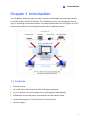
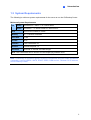
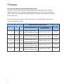
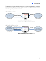
GV-Backup Center User's Manual V1.1.1.0 BCV111-A © 2013 GeoVision, Inc. All rights reserved. Under the copyright laws, this manual may not be copied, in whole or in part, without the written consent of GeoVision. Every effort has been made to ensure that the information in this manual is accurate. GeoVision, Inc. makes no expressed or implied warranty of any kind and assumes no responsibility for errors or omissions. No liability is assumed for incidental or consequential damages arising from the use of the information or products contained herein. Features and specifications are subject to change without notice. GeoVision, Inc. 9F, No. 246, Sec. 1, Neihu Rd., Neihu District, Taipei, Taiwan Tel: +886-2-8797-8377 Fax: +886-2-8797-8335 http://www.geovision.com.tw Trademarks used in this manual: GeoVision, the GeoVision logo and GV series products are trademarks of GeoVision, Inc. Windows and Windows XP are registered trademarks of Microsoft Corporation. June 2013 Contents Naming and Definition .......................................................................... iii Chapter 1 Introduction.......................................................................... 1 1.1 Features .....................................................................................................................1 1.2 Compatible Version....................................................................................................2 1.3 System Requirements................................................................................................3 1.4 Data Transfer Time between Different Network Types ..............................................6 Chapter 2 Installation............................................................................ 7 Chapter 3 Getting Started..................................................................... 8 3.1 Starting the GV-Backup Center..................................................................................8 3.2 Connecting GV-IP Devices ........................................................................................9 3.2.1 Setting Backup Frequency.............................................................................11 3.3 Connecting GV-System............................................................................................12 3.4 The Main Screen of GV-Backup Center...................................................................16 3.5 Assigning Backup Locations ....................................................................................18 3.6 Setting E-Mail Notifications ......................................................................................20 3.6.1 Setting Mail Server ........................................................................................20 3.6.2 Setting E-Mail Alerts ......................................................................................21 Chapter 4 Configuring the GV-Backup Center ................................. 23 4.1 General Settings ......................................................................................................23 4.2 Account Settings ......................................................................................................24 4.3 Storage Settings.......................................................................................................25 4.4 Database Settings....................................................................................................26 4.5 E-Mail Settings .........................................................................................................26 4.6 File Transfer Settings ...............................................................................................27 4.7 UPnP Port Mapping Settings ...................................................................................30 Chapter 5 Accessing the Backup Data Using a Web Browser........ 31 5.1 Accessing the Web Interface ...................................................................................31 5.2 Tree Menu................................................................................................................33 5.3 System Event List Query..........................................................................................35 5.4 Login and Logout Query...........................................................................................36 5.5 Monitor Event List Query..........................................................................................37 5.6 Analysis by Event Count ..........................................................................................38 5.7 Analysis by Event File Size ......................................................................................39 i 5.8 Analysis by Time ......................................................................................................40 5.9 Analysis of File Size by Time ...................................................................................41 Chapter 6 Remote Playback ............................................................... 42 Specifications……………………………………………………………….44 Appendix……………………………………………………………………..45 A. Enabling UPnP in Windows XP .................................................................................45 B. Modifying Port Number for running GV-Backup Center on the same computer with GV-System......................................................................................................................46 C. Installing .Net Framework 3.5 for Windows Server 2012 and Windows 8.................47 ii Naming and Definition GV-System GeoVision Analog and Digital Video Recording Software. The GVSystem also refers to GV-Multicam System, GV-NVR System and GV-Hybrid DVR System at the same time. iii 1 Introduction Chapter 1 Introduction The GV-Backup Center provides you with a secure and affordable remote backup solution for the GV-System and GV-IP Devices. The GV-Backup Center can automatically store a copy of recordings to the offsite location. If a disaster strikes where the GV-System or GV-IP Devices are located, the recording data remain safe in a different location. 1.1 Features Remote backup Up to 200 units of GV-System and GV-IP Devices supported Up to 10 backup rules for working and non-working days independently E-Mail alerts for low disk space, disconnection and file transfer failure Online data analysis by Event Counts, File Size and Time Failover support 1 1.2 Compatible Version GV-Video Server: GV-VS02A firmware version 1.03 or later GV-VS04A firmware version 1.02 or later GV-VS04H firmware version 1.04 or later GV-VS12 firmware version 1.03 or later GV-VS14 firmware version 1.00 or later GV-Compact DVR V2: firmware version1.04 or later GV-Compact DVR V3: firmware version 1.00 or later GV-System: version 8.5.5 or later GV-IP Devices: GV-BX120D-E / 220D-E / 320D-E / 520D-E firmware version 1.03 or later GV-BX120D / 140DW / 130D / 220D / 320D / 520D / 2400 Series / 3400 Series firmware version 1.03 or later GV-BL120D / 130D / 220D / 320D firmware version 1.03 or later GV-FD120D / 220D / 320D firmware version 1.03 or later GV-MFD120 / 130 / 220 / 320 / 520 firmware version 1.03 or later GV-MDR120 / 220 / 320 / 520 firmware version 1.03 or later GV-VD120D / 220D / 320D firmware version 1.03 or later GV-CA120 / 220, GV-CAW120 / 220 firmware version 1.03 or later GV-CB120 / 220, CBW120 / 220 firmware version 1.03 or later GV-FE420 / 421 / 520 / 521, GV-FER521 firmware version 1.03 or later GV-SD220 / GV-SD220-S firmware version 1.00 or later Note: GV-System backup only works with GV-Backup Center V1.10 or later. 2 1 Introduction 1.3 System Requirements The following is minimum system requirements for the server to run the GV-Backup Center. Minimum System Requirements OS 32-bit Windows XP / Vista / 7 / 8 / Server 2008 64-bit Windows 7 / 8 / Server 2008 R2 / Server 2012 CPU Core 2 Duo, E6600, 2.4 GHz Memory 2 x 1 GB Dual Channels Hard Disk 1 GB DirectX 9.0c Software .Net Framework 3.5 Browser Internet Explorer 7.x Hardware External or Internal GV-USB Dongle Note: .Net Framework can be found in the accompanying software DVD. Note: Considering of connection speed, we do not recommend using the mobile broadband connection, such as HSDPA, UMTS, EDGE, GPRS, GSM and etc., between GV IP devices and GV-Backup Center. 3 Recommended Network and Hard Disk Requirements The server’s backup speed and transmitting capacity vary depending on the number of Gigabit connections. The numbers of Gigabit network cards required to receive 200 hosts and to support remote access of backed up data are listed below according to the resolution of the source video. Also note the maximum number of hosts supported by a single hard disk to calculate the number of hard disks required. Gigabit Network Cards Required Resolution FPS Codec Receiving 200 hosts 4 1.3 M 30 fps H.264 2.0 M 30 fps H.264 3.0 M 20 fps H.264 4.0 M 15 fps H.264 5.0 M 10 fps H.264 Gigabit network card x 2 (up to 100 hosts per card) Gigabit Network Card x 3 (up to 67 hosts per card) Gigabit network card x 2 (up to 100 hosts per card) Gigabit Network Card x 3 (up to 67 hosts per card) Gigabit Network Card x 3 (up to 67 hosts per card) For Playback / Web Query access Max. hosts per HDD Gigabit Network Card x 1 32 hosts Gigabit Network Card x 1 21 hosts Gigabit Network Card x 1 32 hosts Gigabit Network Card x 1 24 hosts Gigabit Network Card x 1 24 hosts 1 Introduction The deployment of Gigabit connections for backing up and accessing database is suggested as illustrated below. Ensure to run every Gigabit connection on a different network in order to reduce the lag on any network connection. 1 MP / 3 MP Source Video GigaLAN 1, 100 Hosts GV-System, GV-IP Devices GigaLAN 3 GigaLAN 2, 100 Hosts Web Query, Remote Playback Up to 100 users Up to 200 units Server installed with GV-Backup Center + 3 Network Cards assigned on different networks 2 MP / 4 MP / 5 MP Source Video GigaLAN 1, 67 Hosts GV-System, GV-IP Devices GigaLAN 2, 67 Hosts GigaLAN 3, 66 Hosts GigaLAN 4 Web Query, Remote Playback Up to 100 users Up to 200 units Server installed with GV-Backup Center + 4 Network Cards assigned on different networks 5 1.4 Data Transfer Time between Different Network Types When the data is transmitted from the GV-IP Devices to the GV-Backup Center, the data transfer time will vary between different network types. The following test is conducted on the GV-Compact DVR V2 to transmit one-day data through WiFi wireless (802.11n) and 10/100 Ethernet LAN. The test is based on these conditions: GV IP Device: GV-Compact DVR V2 Video Size: 720 x 480 Data Size: 81.92 mb Data Amount for One Channel: 288 video clips/ day For the data transfer of one channel, the transfer time for Full Videos is 2 hr 24 min through WiFi wireless, and 1 hr 16 min through Ethernet LAN. If you select to transmit Compact Videos (key frames only), the transfer time is significantly reduced to 28 min 48 sec through WiFi wireless and 19 min 12 sec through Ethernet LAN. For the data transfer of four channels, the transfer time for Full Videos is 8 hr 14 min through WiFi wireless, and 5 hr 04 min through Ethernet LAN. If you select to transmit Compact Videos (key frames only), the transfer time is significantly reduced to 1 hr 55 min through WiFi wireless and 1 hr 16 min through Ethernet LAN. Network Type 1 Ch / 1 Day 4 Ch / 1 Day Data Transfer Time Data Transfer Time Full Videos 2 hr 24 min 8 hr 14 min Compact Videos 28 min 48 sec 1 hr 55 min 10/100 Full Videos 1 hr 16 min 5 hr 04 min Ethernet Compact Videos 19 min 12 sec 1 hr 16 min WiFi (802.11n) Video Type Note: To only transmit key frames to the GV-Backup Center, you should configure the Compact Video setting on the Web interface of GV-IP Devices (Figure 3-2). 6 2 Installation Chapter 2 Installation The GV-Backup Center program may be installed on a separate computer or the same computer with the GV-System, but it is recommended to install on a dedicated computer. Before installing the GV-Backup Center, you need to plug the GV-USB Dongle to the computer, and then install the dongle driver and Microsoft .Net Framework. Follow the steps below to install the programs. 1. Insert Software DVD to the computer. It runs automatically and a window appears. 2. To install USB driver, select Install or Remove GeoVision GV-Series Driver and click Install GeoVision USB Devices Driver to start. 3. To install .Net Framework, select Download Microsoft .NET Framework 3.5 to start. Note: If you are a user of Windows 8 or Windows Server 2012, see How to install .Net Framework 3.5 for Windows Server 2012 and Windows 8 in Appendix C 4. To install GV-Backup Center, select GV-Backup Center System V1.1.1.0. Figure 2-1 7 Chapter 3 Getting Started The GV-Backup Center is a dedicated computer on a network that stores backup copies of recordings from up to 200 units of GV-System and GV-IP Devices. The GV-Backup Center allows you to access those backup data anywhere through a web browser. 3.1 Starting the GV-Backup Center To start the GV-Backup Center, follow these steps: 1. Run GV-Backup Center. The first-time user will be prompted to enter a password. The default login account is admin and password is left blank. Figure 3-1 2. On the GV-Backup Center window, click Service from the menu bar and select Start all services to store backup data from connected GV-System and GV-IP Devices. 8 3 Getting Started 3.2 Connecting GV-IP Devices You need to configure the GV-IP devices in order to back up data to the GV-Backup Center remotely over a network. Different backup schedules are definable on each GV-IP devices. You can also configure up to two GV-Backup Centers in case of the primary center failure. Whenever the primary GV-Backup Center fails, the second GV-Backup Center takes over the connection from GV-IP devices, providing uninterrupted backup services. 1. Access the Web interface of GV-IP devices, and select Backup Center. Figure 3-2 2. Select Activate Link. 3. Type IP address or domain name of GV-Backup Center. 4. Keep the default port number 30000. Otherwise, modify the port number to match Listen Port number on the GV-Backup Center (Figure 4-1). 5. Type User Name and Password to log onto the GV-Backup Center. These entries must match the account and password created on the GV-Backup Center (Figure 4-2). The default login account is admin and password is left blank. 6. In the Backup Video section, select the cameras that you want to back up their recordings to the GV-Backup Center. 7. In the Compact Video section, select the cameras that you only want to back up their Key Frames to the GV-Backup Center, instead of full recordings. This option is useful to save the backup time. 9 8. Select Reset all files in case of the network interruption. After the network is recovered, all the missing data will be resent to the GV-Backup Center again. 9. If there is the other GV-Backup Center for failover support, select Automatic Failover Support and type its connection information. 10. Optionally set up the schedule to back up data to the GV-Backup Center. 11. Click Apply to start connection. Ensure Data Service on the GV-Backup Center has been enabled; otherwise the connection attempt will fail. When the connection is established, a message “Status: Connected. Connected Time:xxx” will be displayed at the bottom of the GV IP Device’s Web interface. On the GV-Backup Center, you can also see the online GV IP Device icon, as the example below. Figure 3-3 10 3 Getting Started 3.2.1 Setting Backup Frequency The backup is created soon after the recordings are stored to the hard drive of GV-IP devices. Therefore, the backup frequency is based on the Split Interval setting for time length of each event file on the GV-IP Devices. You can specify the backup frequency between 1 and 5 minutes. Figure 3-4 11 3.3 Connecting GV-System You need to configure the GV-System in order to back up the recordings to the GV-Backup Center remotely over a network. Note: The GV-System backup is only supported in GV-Backup Center V1.1.0.0 or later. 1. Click the Network button and select Connect to Backup Center. This dialog box appears. Figure 3-5 2. Type IP address or domain name of GV-Backup Center. 3. Type User Name and Password to log onto the GV-Backup Center. These entries must match the account and password created on the GV-Backup Center (Figure 4-2). The default ID and Password are admin. 4. Keep the default port number 30000. Otherwise, modify the port number to match Listen Port number on the GV-Backup Center (Figure 4-1). 12 3 Getting Started 5. Click OK. The login information is added. Figure 3-6 6. Click Advanced Settings to specify the interval between each connection retry when connection is interrupted. Figure 3-7 7. Click OK and click the Connect button to connect to GV-Backup Center. Ensure Data Service on the GV-Backup Center has been enabled; otherwise the connection attempt will fail. When the connection is established, you can see the online DVR icon on the GV-Backup Center, as the example below. Figure 3-8 13 Note: 1. The round-the-clock events will be resent and backed up to the GV-Backup Center when the connection to GV-Backup Center is disabled and later enabled on the GVSystem. However, to back up motion and input trigger events, ensure the connection to the GV-Backup Center is always enabled. Figure 3-9 2. To back up motion events recorded on the GV-System, make sure to select Register Motion Event for each camera (Configure button >System Configure > Camera Configure). Figure 3-10 14 3 3. Getting Started To back up input trigger events recorded on the GV-System, make sure to select Register Input Event for each input device (Configure button > Accessories > I/O Device > I/O Application). Figure 3-11 15 3.4 The Main Screen of GV-Backup Center 5 6 7 8 9 1 2 3 4 Figure 3-12 No Name Description 1 Host List Displays connected GV-System and GV-IP devices. 2 Storage Window Displays the storage drives and space information. 3 4 16 File Transfer Window Server Window Displays the information and progress of file transferring. Displays the server information of GV-Backup Center. 3 Getting Started Enables and disables the following GV-Backup Center services: 5 Service Data Service: Enables connection to GV-System and GV-IP Devices. Web Service: Enables access to the GV-Backup Center’s Web interface. ViewLog Service: Enables remote access to the backup recordings on the GV-Backup Center. 6 Browse Links to the Web interface of GV-Backup Center. 7 Tools Accesses the advanced settings. See Chapter 4 Configuring the GV-Backup Center. 8 9 Server Status Tab Events Tab Displays the storage, file transfer and server information of GVBackup Center. Displays the current connection and file transfer status. The list of status events will automatically cleared each time the GV-Backup Center is restarted. The status events can be retrieved and filtered through the Web interface of GV-Backup Center. 17 3.5 Assigning Backup Locations The backup location is where the recordings from GV-System and GV-IP Devices will be stored on the GV-Backup Center. You can assign different backup locations for each GV IP device and GV-System to back up its own recordings. The default backup location is at C:\BackupSvr. 1. Click Tools from the menu bar, select Setting and click Storage. The Storage Settings dialog box appears. 2. In the Storage list, select the Disk that you want to use as the backup location on the GV-Backup Center. Figure 3-13 3. 18 Click Apply. 3 4. Getting Started To assign a disk for the GV IP device, right-click one GV IP device on the Host List, and select Host Setting. This dialog box appears. Figure 3-14 5. Select Use First Available Storage in Storage Setting to use the first available disk as the backup location for the GV IP device. Otherwise, select A Specified Storage and select one disk to be the backup location for the GV IP device. 6. Click OK. Note: It is recommended to install one hard disk for every 50 connected GV IP devices due to the data transfer limit of the hard disk. For the maximum of 200 connected GV IP devices, you need to install at least 4 hard disks. 19 3.6 Setting E-Mail Notifications The supervisor can be warned by e-mail messages when any disk space falls below certain threshold, any GV-System or IP device is disconnected with the GV-Backup Center or file transfer fails. For the e-mail alert function, follow the steps below to set up the mail server first. 3.6.1 Setting Mail Server 1. Click Tools from the menu bar, select Setting and click E-Mail. This dialog box appears. Figure 3-15 2. Type URL or IP address of the SMTP server. 3. Type the e-mail address where e-mails are sent from. The entered e-mail will appear as sender when the e-mail is received. 4. Type e-mail addresses of recipients. For multiple recipients, add a semicolon between each e-mail address. 5. Type a subject coming with the alert message. 6. Click Test E-Mail Account to send out a test e-mail to see whether the setup is correct. If the connection attempt fails, you may also need to check the settings of SMTP Authentication Setting and SMTP Server Settings described below. Other options on the dialog box: [SMTP Authentication Setting] If the SMTP server needs authentication, select this option and type your account name and password. 20 3 Getting Started [SMTP Server Setting] Keep the default port 25 which is common for most SMTP servers. However webmail providers such as Yahoo and Hotmail generally use different SMTP port. In this case, check with e-mail providers for SMTP port number. Select SSL if the SMTP server requires the SSL authentication for connection. 3.6.2 Setting E-Mail Alerts Setting Low Disk Space Alerts When any disk space on the GV-Backup Center is lower than the specified limit, e-mails will be sent out to warn the supervisor. 1. Click Tools from the menu bar, select Setting and click Storage. The Storage Setting dialog box appears (Figure 3-13). 2. Specify the limit of free space of each disk in the Alert when the disk free space is less than field. 3. Select Send an e-mail when the disk free space low. 4. Click Apply. Setting Alerts for Disconnection and File Transfer Failure The supervisor can be warned by e-mail messages when any GV-IP Device or GV-System is disconnected from the GV-Backup Center, or file transfer is interrupted. 1. On the Host List, right-click one GV IP device and select Host Setting. The Host Setting dialog box appears (Figure 3-14). 21 2. Click the Notification tab. This dialog box appears. Figure 3-16 3. To send e-mail alerts when the GV IP device or GV-System is disconnected from the GV-Backup Center, select Send E-Mail Notification when disconnected. 4. To send e-mail alerts when the file transfer from the GV IP device fails, select Send EMail Notification when file transfer fails. 5. 22 Click OK. 4 Configuring the GV-Backup Center Chapter 4 Configuring the GV-Backup Center To access more settings of GV-Backup Center, click Tools from the menu bar and select Setting or UPnP Port Mapping Setting. This chapter describes these advanced settings: General Setup, Account, Storage, Database, E-Mail, File Transfer and UPnP Port Mapping. 4.1 General Settings The General Settings allow you to configure the communication ports of GV-Backup Center and automatic startup services. Figure 4-1 [Backup Center] Server Name: Names the GV-Backup Center. The default value is the computer name. Listen Port: The default communication port of GV-Backup Center is 30000. Max Client Limit: Specifies the maximum number of connections from GV-IP Devices and GV-System allowed to access the GV-Backup Center. The maximum value is 200. Auto Start Service: Automatically starts connection to configured GV-IP Devices and GV-Systems once the GV-Backup Center is started. [ViewLog Server] Listen Port: The port allows remote access to the backup recordings on the GV-Backup Center. 23 Auto Start Service: Automatically enables the remote playback service once the GVBackup Center is started. [Web Server] Listen Port: The HTTP port allows connecting the GV-Backup Center to the Web. Auto Start Service: Automatically enables remote access to the Web interface of GVBackup Center once the GV-Backup Center is started. Auto startup after login Windows: Automatically starts the GV-Backup Center after Windows startup. Start Auto login: Automatically logs onto the GV-Backup Center after Windows startup. Click the Arrow button to enter the account and password for the automatic login. 4.2 Account Settings Using the Account Settings, you can create new accounts with different access rights. Up to 100 accounts, including Users and Supervisors, can be created. Figure 4-2 Under the General Setup tab, there are two options: Allow Web Login: Allows the user to access the Web interface of GV-Backup Center. Allow Remote Playback: Allows the user to remotely access the backup recordings on the GV-Backup Center. 24 4 Configuring the GV-Backup Center Note: The Allow Live View Option on the Account Settings dialog box is NOT functional. 4.3 Storage Settings The Storage Settings allow you to specify the backup locations, free space limit and low free space alerts. Figure 4-3 [Storage] In the Storage list, select the disks to be storage locations. Alert when the disk’s free space is less than xx GB: When any disk space is less than the specified limit, e-mail alerts will be sent to warn you. See 3.5.2 Setting E-Mail Alerts. Enable recycling when free space is less than xx GB: When the free space of each disk is less than the specified limit, old recordings on that disk will be overwritten. Every time the data of 2 GB will be deleted. Keep Days: Specify the number of days to keep the recordings from 0 (unlimited) to 999 days. When Enable recycling when free space is less than xx GB and Keep Days are both selected, the system applied whichever condition comes first. For example, if the specified smallest amount of storage space comes earlier than the specified Keep Days, then recycling is applied first. [Disk Notify] Send an e-mail when the disk free space is low: Enables the e-mail alert when any disk space is less than the specified limit. See 3.5.2 Setting E-Mail Alerts. 25 4.4 Database Settings You can modify the storage path of GV-Backup Center’s database (system log) and specify the number of days to keep the database. When the Recycle option is selected, some part of the database will be overwritten when the storage space is lower than 500 MB. When Recycle and Keep Days are both selected, the system applies whichever condition comes first. For example, if the low storage space (500 MB) comes earlier than the specified Keep Days, then recycle is applied first. If the operating system of GV-Backup Center is of NTFS file system, you can select Enable Database Compression to save disk space. Figure 4-4 4.5 E-Mail Settings To configure the mail server to send alerts, see 3.5.1 Setting Mail Server. 26 4 Configuring the GV-Backup Center 4.6 File Transfer Settings In this setting dialog box, you can define the following backup rules: The day to back up the recordings. The time period of recordings to be transferred. The type of recording to be transferred, including motion detection, I/O trigger or all types of events. The time to back up the files. Figure 4-5 [Working Days] In this tab, you can define up to 10 backup rules for working days, which include which working day, which camera and which type of recording to be transferred to the GV-Backup Center. 1. Select the day, including Monday to Sunday. 2. Click the arrow button before Time Span and select Modify. Figure 4-6 27 3. In this dialog box, select the Camera that you want to back up its recordings, specify Time Span in which time period of recordings to be transferred, and select Events that you want to back up all event files, or Motion and/or I/O trigger events only. Figure 4-7 4. Click OK. The backup settings are created. 5. To define another backup rule, click the button. A new Time Span is created. Figure 4-8 6. 28 Click the arrow button, select Modify and follow the step 3 to define the backup rule. 4 Configuring the GV-Backup Center [Holidays] In this tab, you can define up to 10 backup rules for non-working days, which include which non-working day, which camera and which type of recording to be transferred to the GV-Backup Center. For how to set up a rule, see the instructions in the above [Working Days]. [Transfer Time] In this tab, you can define the time to back up the files from the GV IP devices to the GV-Backup Center, based on the rules you set up for working days and nonworking days. 29 4.7 UPnP Port Mapping Settings The GV-Backup Center supports UPnP technology (Universal Plug and Play) to allow automatic port configuration to your router. In order for UPnP to be enabled, the following requirements must be met: Windows XP Service Pack 2 or later Windows operating system has been configured to use UPnP. See Enabling UPnP in Windows XP in Appendix. UPnP has been enabled on your router. For this setting, consult your router’s documentation. To enable UPnP on the GV-Backup Center: 1. Click Tools from the menu bar and select UPnP Port Mapping Setting. This dialog box appears. Figure 4-9 2. Click Searching to search the UPnP-enabled routers. 3. If your server is installed with multiple routers, select a desired one from the UPnP-based Router drop-down list. 4. If your server is installed with multiple network adapters, select a desired one from the drop-down list. 5. Click Configure to automatically configure the communication ports on the router. Tip: If you don’t use the default ports 3000, 5552 and 80, modify the related ports in the General Setup dialog box (Figure 4-1), re-open the UPnP port mapping dialog box and follow above steps to configure your router. 30 5 Accessing the Backup Data Using a Web Browser Chapter 5 Accessing the Backup Data Using a Web Browser After the GV-Backup Center service is started, the backup data are accessible through network. Note: For remote viewing through network, Internet Explorer 7.0 or later is required. 5.1 Accessing the Web Interface To access the GV-Backup Center through the network, ensure the Web Service (No. 5, Figure 3-11) on the GV-Backup Center has been enabled; otherwise the access to the web browser will fail. 1. Two methods to access the Web interface of GV-Backup Center: A. If you are at the local GV-Backup Center, select Browse from the menu bar and select Event Data. The login page appears. B. If you are at a remote computer, start the Internet Explorer browser. Enter the IP address or the domain name of GV-Backup Center in the Location/Address field of your browser. The login page appears. Figure 5-1 2. Enter the login ID and Password of GV-Backup Center. 3. Enter the characters shown in the image. 31 4. Click Login. The web page similar to the following example is now displayed in your browser. Figure 5-2 32 5 Accessing the Backup Data Using a Web Browser 5.2 Tree Menu On the left side of the Web interface, you can see the tree menu. Figure 5-3 Backup Center This category is for searching the whole backup data on the GVBackup Center by certain criteria. System Event List Query: Searches the system-related events of GV-Backup Center. Login/Logout Query: Searches the login and logout events during a specified period of time. Monitor Event List Query: Searches the desired events during a specified period of time. Analysis by Event Count: Displays the relative number of all events during a specified period of time. Analysis by Event File Size: Displays the relative file size of all events during a specified period of time. Analysis by Time: Displays the relative number of all events by year, month or date. Analysis of File Size by Time: Displays the relative file size of all events by year, month or date. Video Server This category is for searching the backup data of GV-Video Server(s) and GV-Compact DVR(s) by certain criteria. 33 Server Management Hard Disk Space Monitor displays the space information of storage drives on the GV-Backup Center. My Favorite Lists the saved search criteria. 34 5 Accessing the Backup Data Using a Web Browser 5.3 System Event List Query The System Event List Query page shows a list of system-related events for a selected period of time. The System Event List Query in the Backup Center category (see 5.2 Tree Menu) allows you to access the File Transfer events of GV-Backup Center. The System Event List Query in the Video Server category (see 5.2 Tree Menu) provides the system events of GV-System and GV-IP Devices, such as Reboot, Video Lost and etc. To define search criteria: 1. In the Backup Device section, select one GV-Backup Center or Select All. 2. In the Login Device section, select desired GV IP devices or Select All. 3. In the Event Type section, select one type of event or Select All. 4. In the Time section, select a period of time. 5. Click Query to display the search results. Figure 5-4 You can click the Add Favorite button to save the search criteria to the Favorite List for future use. You can also click the Export CSV and Export Word buttons to export the search results in EXCEL and WORD formats respectively. 35 5.4 Login and Logout Query If you want to know which user accounts have logged into the GV-Backup Center, GVSystem or GV-IP Devices during a specified period of time, the Login/Logout Query page can give you answer. To define search criteria: 1. In the Backup Device section, select one GV-Backup Center or Select All. 2. In the Login Device section, select desired GV IP devices or Select All. 3. In the User Name section, type an account name. You can also leave the field blank to search all accounts. 4. In the Login/Logout section, select Login, Logout or Select All. 5. In the Time section, select a period of time. 6. In the Status section, select Fail or Success. 7. Click Query to display search results. Figure 5-5 You can click the Add Favorite button to save the search criteria to the Favorite List for future use. You can also click the Export CSV and Export Word buttons to export the search results in EXCEL and WORD formats respectively. Note: The Mode and DST options on the Login/Logout Query are NOT functional. 36 5 Accessing the Backup Data Using a Web Browser 5.5 Monitor Event List Query The Monitor Event List Query page helps you locate the desired events during a specified period of time. The query results contain video preview and clip for further identification. To see video preview or clip, ensure ViewLog Service on the GV-Backup Center is enabled. To define search criteria: 1. In the Camera section, click desired GV IP devices to display the contained cameras. Then select desired cameras. 2. In the Event Type section, select one type of event or Select All. 3. In the Time section, select a period of time. 4. Click Query to display search results. Figure 5-6 You can click the Add Favorite button to save the search criteria to the Favorite List for future use. You can also click the Export CSV and Export Word buttons to export the search results in EXCEL and WORD formats respectively. 37 5.6 Analysis by Event Count The Analysis by Event Count page shows the relative number of event types for a selected period of time. The search results can be displayed in three graph types: Bar, Pie and Line. To define search criteria: 1. In the Camera section, click desired GV IP devices to display the contained cameras. Then select desired cameras. 2. In the Event Type section, select one type of event or Select All. 3. In the Time section, select a period of time. 4. Select one type of graph. 5. Click Query to display search results. For the example below, we select Select All as Event Type and select Bar Graph to display search results. The Bar Graph shows the relative number of all events. The horizontal axis displays the type of event. In this case there are only two event types Motion Detection and Round-the-Clock. The vertical axis displays the number of events occurred in the selected cameras. When we move the mouse pointer over the bar graphic, the exact number of events will be displayed. Figure 5-7 You can click the Add Favorite button to save the search criteria to the Favorite List for future use. You can also click the Print button to print out the graph. 38 5 Accessing the Backup Data Using a Web Browser 5.7 Analysis by Event File Size The Analysis by Event File Size page shows the relative file size of all events for a selected period of time. The search results can be displayed in three graph types: Bar, Pie and Line. To define search criteria, see 5.7 Analysis by Event Count. For the example below, we select Select All as Event Type and select Bar Graph to display search results. The Bar Graph shows the relative file size of all events. The horizontal axis displays the type of event. In this case there are only two event types Motion Detection and Round-the-Clock. The vertical axis displays the file size of events occurred in the selected cameras, in the unit of MB. When we move the mouse pointer over the bar graphic, the exact file size of events will be displayed. Figure 5-8 You can click the Add Favorite button to save the search criteria to the Favorite List for future use. You can also click the Print button to print out the graph. 39 5.8 Analysis by Time The Analysis by Time page shows the relative number of all events by year, month or date. This analysis is useful to determine the peak time of events. To define search criteria, see 5.7 Analysis by Event Count. For the example below, we select All Cameras, select By Day as Period Type, specify the date as March 31, 2010, and select Pie Graph to display search results. The Pie Graph shows the relative proportion of events by hour for the specified date. When we move the mouse pointer over each sector, the exact number of events will be displayed. Figure 5-9 40 5 Accessing the Backup Data Using a Web Browser 5.9 Analysis of File Size by Time The Analysis of File Size by Time page shows the relative file size of all events by year, month or date. The search results can be displayed in three graph types: Bar, Pie and Line. To define search criteria, see 5.7 Analysis by Event Count. For the example below, we select All Cameras, select By Day as Period Type, specify the date as March 31, 2010, and select Line Graph to display search results. The Line Graph shows the relative file size of all events hourly on the specified date. When we move the mouse pointer over each sector, the exact file size of events will be displayed. Figure 5-10 41 Chapter 6 Remote Playback With the Remote ViewLog program installed in any computer, you can play back the backup recordings. For the remote playback to work, ensure ViewLog Service on the GV-Backup Center has been enabled. Note: To remotely play back recordings, you can also use the Monitor Event List Query page on the Web interface of GV-Backup Center. See 5.5 Monitor Event List Query. 1. Install and run the Remote ViewLog from Software DVD. You can find the Remote ViewLog program by selecting Install GeoVision Free Utility from the Software DVD menu. Note: When the Remote ViewLog is started, it will pop up the selections of Remote ViewLog Server and Remote Storage System. Just click any place on the window to ignore and close the pop-up window. 2. On the functional bar, click the Tools button and select Address Book. The Address Book appears. 3. On the toolbar, click the Add GV-Backup Center button . This dialog box appears. Figure 6-1 4. Type the IP address, login ID and password of GV-Backup Center. Click OK to connect to the GV-Backup Center. Ensure ViewLog Service on the GV-Backup Center has been enabled; otherwise the connection attempt will fail. 42 6 5. Remote Playback Expand Host List. The GV-Backup Center is now added to the address book. Expand the GV-Backup Center folder and select the desired GV IP device. Figure 6-2 6. To access the backup data of the selected GV IP device, click the Connect button . You will be prompted for the login ID and Password of GV-Backup Center again. After logging into the GV-Backup Center, the backup events of that GV IP device will be displayed on the Event List. 7. Select the desired event and click the Play button to start playback. 43 Specifications Number of hosts 200 units of GV-System and GV-IP Devices Number of user accounts 100 in total including Supervisors and Users Backup schedule Yes (for GV-System and GV-IP Devices) Backup rules 10 rules for working and non-working days independently Resuming backup after losing connection to hosts Yes E-mail alert Low disk space, disconnection, file transfer failure Disk space recycle Yes Keep Day Definable and unlimited in number System Log query Web-based query pages Available through web-based query pages, or Remote Video playback ViewLog Playback program additionally installed from Software DVD Language Danish, English, French, German, Hebrew, Hungarian, Italian, Japanese, Polish, Portuguese, Russian, Serbian, Simplified Chinese, Spanish, Traditional Chinese, Turkish All specifications are subject to change without notice. 44 Appendix Appendix A. Enabling UPnP in Windows XP 1. Go to Windows Start, click the Start button, select Settings, and select Network Connections. This window appears. 2. Right-click one Local Area Connection, select Properties, and click the Advanced tab. This dialog box appears. 3. Click the Settings tab, and click Exceptions tab. This dialog box appears. 4. Select UPnP Framework, and click OK 45 B. Modifying Port Number for running GV-Backup Center on the same computer with GV-System Since the GV-Backup Center and the WebCam Server of GV-System use the same HTTP port number of 80 to connect to the Web, it is required to modify the port number of either GV-Backup Center or WebCam Server if both are run on the same computer. If not, the following message will appear and you cannot access the Web interface of GV-Backup Center: Starting Web Server Failed To modify the HTTP port number of GV-Backup Center: 1. Click Tools from the menu bar and select General Setup. 2. Change the listen port of Web Server from 80 to a different port number, e.g 81. 3. Click Apply. 46 Appendix C. Installing .Net Framework 3.5 for Windows Server 2012 and Windows 8 Follow the steps below to manually install .Net Framework 3.5 for Windows Server 2012 and Windows 8. Windows Server 2012: 1. Open Server Manager from the Start menu. 2. Click Dashboard from the tree list on the left and click Add roles and features. 47 3. Click Features from the tree list on the left and select .Net Framework 3.5 Features. 4. Select .Net Framework 3.5 (include 2.0 and 3.0) and click the Install button. 48 Appendix Window 8 1. Click Control Panel from the Start menu. 2. Click the Programs icon. 3. Select Turn Windows features on or off under the Programs and Features title. 4. Select .Net Framework 3.5 (includes .Net 2.0 and 3.0) and click the OK button. 49