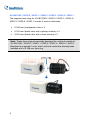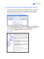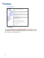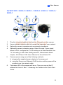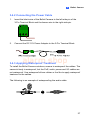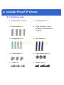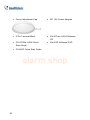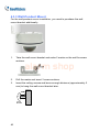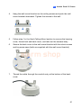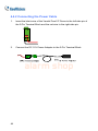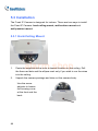
1
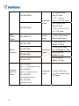
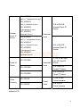
alarm shop
© 2011 GeoVision, Inc. All rights reserved.
Under the copyright laws, this manual may not be copied, in whole or in
part, without the written consent of GeoVision.
Every effort has been made to ensure that the information in this manual is
alarm shop
accurate. GeoVision, Inc. makes no expressed or implied warranty of any
kind and assumes no responsibility for errors or omissions. No liability is
assumed for incidental or consequential damages arising from the use of
the information or products contained herein. Features and specifications
are subject to change without notice.
GeoVision, Inc.
9F, No. 246, Sec. 1, Neihu Rd.,
Neihu District, Taipei, Taiwan
Tel: +886-2-8797-8377
Fax: +886-2-8797-8335
http://www.geovision.com.tw
Trademarks used in this manual: GeoVision, the GeoVision logo and GV
series products are trademarks of GeoVision, Inc. Windows and Windows
XP are registered trademarks of Microsoft Corporation.
January 2011
Contents
Introduction .................................................................................iii
Options ........................................................................................vi
Note for Connecting to GV-System ..........................................vii
Note for Adjusting Focus and Zoom .......................................viii
1. Box Camera ..............................................................................1
1.1 Packing List................................................................................. 1
1.2 Overview ..................................................................................... 2
1.3 Accessory Installation ................................................................. 5
1.3.1 C-Mount Lenses ..................................................................5
1.3.2 Infrared Illuminators.............................................................7
1.4 Connecting the Camera .............................................................. 9
2. Mini Fixed Dome.....................................................................13
alarm shop
2.1 Packing List............................................................................... 13
2.2 Overview ................................................................................... 14
2.3 Installation................................................................................. 15
2.4 Adjusting the Focus .................................................................. 16
3. Bullet Camera .........................................................................17
3.1 Packing List............................................................................... 17
3.2 Overview ................................................................................... 18
3.3 Installation................................................................................. 19
3.3.1 Adjusting the Angles..........................................................20
3.3.2 Adjusting Lens and Inserting a Memory Card....................23
3.3.3 Inserting the Sun-Shield Cover..........................................25
3.4 Connecting the Camera ............................................................ 26
3.4.1 Wire Definition ...................................................................26
3.4.2 Connecting the Power Cable.............................................27
3.4.3 Applying Waterproof Treatment.........................................27
i
4. Vandal Proof IP Dome............................................................29
4.1 Packing List............................................................................... 29
4.2 Overview ................................................................................... 31
4.3 Installation................................................................................. 32
4.3.1 Hard-Ceiling Mount ...........................................................32
4.3.2 In-Ceiling Mount ................................................................37
4.3.3 Wall-Pendent Mount..........................................................40
4.4 Connecting the Camera ............................................................ 43
4.4.1 Wire Definition ...................................................................43
4.4.2 Connecting the Power Cable.............................................44
5. Fixed IP Dome ........................................................................45
5.1 Packing List............................................................................... 45
5.2 Overview ................................................................................... 46
5.3 Installation................................................................................. 48
5.3.1 Hard-Ceiling Mount ...........................................................48
alarm shop
5.3.2 Wall-Surface Mount...........................................................52
5.3.3 Wall-Pendent Mount..........................................................53
5.4 Connecting the Camera ............................................................ 55
6. Cube Camera ..........................................................................57
6.1 Packing List............................................................................... 57
6.2 Overview ................................................................................... 58
6.3 Installation................................................................................. 59
6.4 Connecting the Camera ............................................................ 60
7. Accessing the Camera...........................................................61
7.1 System Requirement ................................................................ 61
7.2 Assigning an IP Address........................................................... 62
8. The Web Interface ..................................................................65
9. Upgrading System Firmware.................................................67
10 Restoring to Default Settings...............................................69
10.1 Using the Web Interface ......................................................... 69
10.2 Directly on the Camera ........................................................... 70
ii
Introduction
Welcome to the GV-IPCam H.264 Quick Start Guide. In this quick guide,
you will find information on the installation and basic configurations of the
Box Camera, Mini Fixed Dome, Bullet Camera, Vandal Proof IP Dome,
Fixed IP Dome and Cube Camera.
Model
Box
Camera
Model No.
GV-BX110D
GV-BX120D
Description
Fixed
Lens
Varifocal
Lens
Varifocal
Lens
1.3 M H.264 D/N
Box IP Cam
1.3 M H.264 Low
Lux D/N Box IP Cam
alarm shop
2 M H.264 D/N Box
IP Cam, Auto Iris IR,
GV-BX220D-0
f: 2.8 ~ 8.5 mm,
F/1.4, 1/3” CS Lens
2 M H.264 D/N Box
IP Cam, Auto Iris IR,
GV-BX220D-1
f: 3.1 ~ 8 mm,
Varifocal
Lens
GV-BX220D-2
F/1.2, 1/3’’ CS Lens
2 M H.264 D/N Box
IP Cam, Auto Iris IR,
f: 2.8 ~ 6 mm,
F/1.3, 1/3’’ CS Lens
GV-BX220D-3
2 M H.264 D/N Box
IP Cam, Auto Iris IR,
f: 2.8 ~ 12 mm,
F/1.4, 1/3’’ CS Lens
iii
3 M H.264 D/N
GV-BX320D-0
Box IP Cam
f: 3.1 ~ 8 mm,
Varifocal
Lens
F/1.2, 1/3’’ CS Lens
3 M H.264 D/N
Box IP Cam
GV-BX320D-1
f: 2.8 ~ 6 mm, F/1.3,
1/3’’ CS Lens
Mini
Fixed
Dome
GV-MFD110
Fixed
Lens
1.3 M H.264 IR
Bullet IP Cam
GV-BL110D
Bullet
Camera
GV-BL120D
1.3 M H.264 Color
Mini Fixed Dome
1.3 M H.264 Low
Lux IR Bullet IP Cam
alarm shop
GV-BL220D
Varifocal
Lens
2 M H.264 IR
Bullet IP Cam
3 M H.264 IR
GV-BL320D
Bullet IP Cam
GV-VD120D
(IK10+, Transparent Cover)
Vandal
GV-VD121D
Proof IP
Dome
(IK10+, Smoked Cover)
GV-VD122D
(Transparent Cover)
GV-VD123D
(Smoked Cover)
iv
Varifocal
Lens
1.3 M H.264 Low
Lux IR Vandal Proof
IP Dome
GV-VD220D
(IK10+, Transparent Cover)
GV-VD221D
(IK10+, Smoked Cover)
2 M H.264 IR
GV-VD222D
Vandal Proof IP
Dome
(Transparent Cover)
Vandal
Proof IP
Dome
GV-VD223D
(Smoked Cover)
GV-VD320D
Varifocal
Lens
(IK10+, Transparent Cover)
GV-VD321D
(IK10+, Smoked Cover)
3 M H.264 IR
GV-VD322D
Vandal Proof IP
Dome
(Transparent Cover)
alarm shop
GV-VD323D
(Smoked Cover)
1.3 M H.264 Low
GV-FD120D
Fixed IP
Dome
GV-FD220D
Varifocal
Lux IR Fixed IP
Dome
Lens
2 M H.264 IR
Fixed IP Dome
3 M H.264 IR
GV-FD320D
Cube
Camera
Fixed IP Dome
1.3 M H.264
GV-CB120
Fixed
GV-CB220
Lens
Cube Camera
2 M H.264
Cube Camera
For a detailed user’s manual, see GV-IPCam H.264 User’s Manual on the
software CD.
v
Options
Optional devices can expand your camera’s capabilities and versatility.
Contact your dealer for more information.
Device
Description
A mountable infrared LED device that improves
image performance of Box Cameras under low
light conditions. Note that the GV-IR LED is only
GV-IR LED
compatible with GV-BX110D and GV-IR LED T2 is
compatible with GV-BX120D / 220D-0 / 220D-1 /
220D-2 / 220D-3 / 320D-0 / 320D-1.
GV-PA191 PoE
Adapter
The GV-PA191 PoE adapter is designed to
provide power and network connection to the
cameras over a single Ethernet cable.
alarm shop
An L-shaped bracket designed for wall mount
Wall Mount Bracket
installation of the Vandal Proof IP Dome and the
Fixed IP Dome.
The housing cover is designed for Vandal Proof IP
Housing Cover
Dome to provide shielding to the camera. Two
types are available: transparent and smoked.
vi
Note for Connecting to GV-System
The GV-IPCAM H.264 is designed to work with GV-System, a hybrid or
digital video management system. Note the following when GV-IPCAM
H.264 is connected to GV-System:
1.
Normally, the images are recorded to the memory card inserted in the
Box Camera, Bullet Camera, Vandal Proof IP Dome, Fixed IP
Dome and Cube Camera. Once the camera is connected to
GV-System for video management or the camera’s Live View is
accessed through the Web browser (see 7. Accessing the Camera in
the Quick Start Guide), the recording to the memory card will be
stopped and the recording will be taken control by GV-System. When
the connection between the camera and GV-System is interrupted, the
alarm shop
recording to the memory card will be resumed to back up the images
on the camera.
2.
Once the camera is connected to GV-System, the resolution set on
GV-System will override the resolution set on the camera’s Web
interface. You can only change the resolution settings through the
Web interface when the connection to GV-System is interrupted.
vii
Note for Adjusting Focus and
Zoom
When adjusting the Focus and Zoom Screws (on Box Camera, Mini Fixed
Dome, Bullet Camera, Vandal Proof IP Dome and Fixed IP Camera),
please do not over tighten the Focus and Zoom screws. The screws only
need to be as tight as your finger can do it; don't bother using any tools to
get them tighter. Doing so can damage the structure of lens.
For example,
alarm shop
Bullet Camera
viii
Fixed IP Camera
1. Box Camera
1.1 Packing List
•
Box Camera
•
Terminal Block
•
Fixed Focal or Varifocal Megapixel Lens
•
C-mount Lens Adapter (BX110D only)
•
Lens Rings (BX120D, BX220D-0 / 220D-1 / 220D-2 / 220D-3,
BX320D-0 / 320D-1 only)
•
Video Out Wire (BX120D, BX220D-0 / 220D-1 / 220D-2 / 220D-3,
BX320D-0 / 320D-1 only)
alarm shop
•
DC 12V Power Adapter
•
GV-IPCAM H.264 Software CD
•
GV-IPCAM H.264 Quick Start Guide
•
GV-NVR Software DVD
•
GV-NVR Quick Start Guide
1.2 Overview
GV-BX110D
alarm shop
2
1
No.
Name
Box Camera
Description
1
Audio Out
Connects a speaker for audio output.
2
Audio In
3
Default
4
Memory Card Slot
5
Video Out
Connects a microphone for audio input.
Resets all configurations to factory default.
See 10. Restoring to Default Settings later
in the Quick Start Guide.
Inserts a micro SD/SDHC card to store
recording data.
Connects to a portable monitor for setting
the focus and angle of Box Camera during
initial installation.
Connects I/O devices. For details, see I/O
Terminal Block, Box Camera chapter
6
I/O Terminal Block
7
LAN / PoE
Connects to a 10/100 Ethernet or PoE.
8
DC 12V Connector
Connects to power.
9
Status LED
10
Microphone
11
Auto Iris Connector
GV-IPCam H.264 User’s Manual on the
software CD.
alarm shop
Status LED
Red Light ON
Reflects system status of the camera. See
the table below.
Records the sounds.
If the varifocal lens is in use, plug the iris
control cable to the connector.
Description
The system powers on and succeeds to
boot up.
Flashing Red and Green
The camera is ready for use with network
Lights
connectivity.
Green Light ON
Error occurs on the system.
3
GV-BX120D / 220D-0 / 220D-1 / 220D-2 / 220D-3 / 320D-0 /
320D-1
11
12
No.
4
Name
Description
1
Video Out
Connects to a portable monitor for setting
the focus and angle of Box Camera during
initial installation.
2
Memory Card Slot
Inserts a micro SD/SDHC card to store
recording data.
3
Audio Out
Connects a speaker for audio output.
4
Audio In
Connects a microphone for audio input.
5
I/O Terminal Block
Connects I/O devices. For details, see I/O
Terminal Block, Box Camera chapter,
GV-IPCam H.264 User’s Manual on the
software CD.
6
Power LED
Indicates the power is supplied.
7
Default
Resets all configurations to factory default.
See 10. Restoring to Default Settings later
in the Quick Start Guide.
8
LAN / PoE
Connects to a 10/100 Ethernet or PoE.
9
DC 12V Port
Connects to power.
10
Auto Iris Connector
Plug the iris control cable to the connector.
alarm shop
11
Microphone
Records the sounds.
12
Status LED
Turns on when the unit is ready for use.
1
Box Camera
1.3 Accessory Installation
1.3.1 C-Mount Lenses
When you use a C-mount lens, it requires a certain distance from the
camera’s imaging chip; otherwise it will not be possible to focus the lens.
Mount the supplied C-mount lens adapter / lens ring to the camera, and
then attach the lens onto the camera body.
GV-BX110D
Install the supplied C-mount lens adapter to extend focal length for
GV-BX110D as illustrated below.
alarm shop
5
GV-BX120D / 220D-0 / 220D-1 / 220D-2 / 220D-3 / 320D-0 / 320D-1
The supplied lens rings for GV-BX120D / 220D-0 / 220D-1 / 220D-2 /
220D-3 / 320D-0 / 320D-1 include 3 sizes in thickness:
•
0.188 mm (transparent color) x 2
•
0.125 mm (black color with a glossy surface) x 2
•
0.254 mm (black color with a matt surface) x 2
Note: These lens rings are specially designed for varifocal models of
GV-BX120D / 220D-0 / 220D-1 / 220D-2 / 220D-3 / 320D-0 / 320D-1.
Besides the supplied 6 units, each varifocal model has already been
installed with a 0.188 mm lens ring.
alarm shop
6
1
Box Camera
1.3.2 Infrared Illuminators (GV-IR LED / GV-IR LED T2)
1.
Connect the infrared illuminator to the terminal block on the camera.
See I/O Terminal Block, Box Camera chapter, GV-IPCam H.264
User’s Manual on the software CD, or GV-IR LED User’s Manual.
2.
3.
Access the Web interface of the camera.
Select Video and Motion, select Video Settings, select Streaming 1
alarm shop
and set the IR Check Function option to be Trigger by Input (for
GV-IR LED) or Trigger IR by D/N (for GV-IR LED T2).
GV-IR LED
7
GV-IR LED T2
4.
alarm shop
Click Apply.
For Trigger by Input and Trigger IR by D/N functions, see the Video
Settings section, Administrator Mode chapter in the GV-IPCam H.264
User’s Manual in the software CD.
8
1
Box Camera
1.4 Connecting the Camera
The Box Camera is designed for indoor use. Please make sure the
installing site is shielded from rain and moisture.
GV-BX110D
alarm shop
1.
If you are using the varifocal lens model, plug the iris control cable to
the Auto Iris Connector on the camera.
2.
Use a standard network cable to connect the camera to your network.
3.
Optionally connect a speaker and an external microphone.
9
4.
Optionally connect a monitor using an RCA video-out wire. If your
signal format is PAL, configure the TV Out setting on its Web interface.
See TV Out setting, in the Video Settings section, Administrator Mode
chapter, GV-IPCam H.264 User’s Manual on the software CD.
5.
Connect power using one of the following methods:
•
•
6.
plugging the supplied power adapter to the DC jack.
using the Power over Ethernet (PoE) function and the power will be
provided over the network cable.
The status LED of the camera will be red. Then you can set the IP
address for the unit. See 7. Accessing the Camera in the Quick Start
Guide.
alarm shop
10
1
Box Camera
GV-BX120D / 220D-0 / 220D-1 / 220D-2 / 220D-3 / 320D-0 /
320D-1
alarm shop
1.
Plug the iris control cable to the Auto Iris Connector on the camera.
2.
Use a standard network cable to connect the camera to your network.
3.
Optionally connect a speaker and an external microphone.
4.
Optionally connect a monitor using a Video Out wire. If your signal
format is PAL, configure the TV Out setting on its Web interface. See
TV Out setting, in the Video Settings section, Administrator Mode
chapter, GV-IPCam H.264 User’s Manual on the software CD.
5.
Connect power using one of the following methods:
•
•
6.
plugging the supplied power adapter to the power port.
using the Power over Ethernet (PoE) function and the power will be
provided over the network cable.
The status LED of the camera will be on. Then you can set the IP
address for the unit. See 7. Accessing the Camera in the Quick Start
Guide.
11
alarm shop
12
2. Mini Fixed Dome
2.1 Packing List
•
Mini Fixed Dome
•
Security Torx
•
Self Tapping Screw x 2
•
Screw Anchor x 2
•
GV-IPCAM H.264 Software CD
•
GV-IPCAM H.264 Quick Start Guide
•
GV-NVR Software DVD
•
GV-NVR Quick Start Guide
alarm shop
2.2 Overview
No.
Name
1
Default Button
2
3
4
5
Lens
Focus Fixed Screw
Tilt Fixed Screw
Built-In Microphone
Description
Resets the GV-MFD110 to factory default.
See 10. Restoring to Default Settings later
in the Quick Start Guide.
Rotates the les right/left to adjust focus.
Loosens the screw to adjust the lens.
Loosens the screw to adjust tilt angle.
Provides one-way audio.
alarm shop
6
6
14
Network/PoE
Connection
Connects the Network cable for power and
Ethernet connection.
2
Mini Fixed Dome
2.3 Installation
The GV-MFD110 is exclusively designed for ceiling mount. Please make
sure the installing site is shielded from rain and moisture.
1.
Take the Mini Fixed Dome and make 2 marks on the ceiling for screw
anchors.
2.
Drill the marks and insert the screw anchors.
3.
Secure the Mini Fixed Dome to the ceiling with the self-tapping screws.
Note: Due to the compact design, the camera can only be powered
using PoE.
alarm shop
15
2.4 Adjusting the Focus
Based on the live image, adjust the camera’s angle and focus by following
the steps below. To access live images, see 7. Accessing the Camera in
the Quick Start Guide
1.
2.
Unscrew the camera’s cover.
alarm shop
Loosen the focus fixed screw, and rotate the lens clockwise or
counterclockwise to adjust focus. Loosen the tilt fixed screw, and
adjust the camera’s tilt angle.
16
3. Bullet Camera
3.1 Packing List
•
Bullet Camera
•
Lens (Megapixel and Built-In 16 IR LEDs)
•
Self Tapping Screw x 3
•
Plastic Screw Anchor x 3
•
Screw Adjuster x 2
•
Sun-Shield Cover Kit (1 Sun-Shield Cover, 2 Philips Head Screws, 2
Plastic Screw Spacers and 2 Hexagon Screws included)
•
Silica Gel Bag x 2 (1 is already placed inside the camera module)
•
3-Pin Terminal Block
•
DC 12V Power Adapter
•
GV-IPCAM H.264 Software CD
•
GV-IPCAM H.264 Quick Start Guide
•
GV-NVR Software DVD
•
GV-NVR Quick Start Guide
alarm shop
3.2 Overview
No.
alarm shop
Name
Description
1
Memory Card Slot
2
Zoom Screw
Receives a Micro SD/SDHC memory card.
Holds the zoom lens in place.
3
Focus Screw
Holds the focus lens in place
4
Default Button
Resets all configurations to factory default.
See 10. Restoring to Default Settings later
in the Quick Start Guide.
18
3
Bullet Camera
3.3 Installation
The Bullet Camera is designed for outdoor use and can be mounted on
ceiling and wall.
1.
Slide the cable clamp to the camera base.
2.
Install the Bullet Camera to the wall / ceiling.
alarm shop
3.
Remove the protection sticker from the camera’s cover.
4.
Connect the network and power cables to the camera. See 3.4.
Connecting the Camera in the Quick Start Guide.
5.
Access and check the live image from the camera. See 7. Accessing
the Camera in the Quick Start Guide.
6.
Adjust the angles of the camera body and the base. Three shafts can
be adjusted. For details, see 3.3.1 Adjusting the Angles in the Quick
Start Guide.
19
7.
Loosen the camera’s cover, adjust lens and focus, and insert a micro
SD/SDHC card into the memory card slot. See 3.3.2 Adjusting Lens
and Inserting a Memory Card in the Quick Start Guide.
8.
Fasten the camera’s cover.
9.
Install the sun-shield cover to the Bullet Camera. For details, see 3.3.3
Installing the Sun-Shield Cover in the Quick Start Guide.
3.3.1 Adjusting the Angles
The Bullet Camera is designed to be adjustable in three shafts.
Tip: The three shafts are designed to offer easy and flexible ceiling / wall
mount installation.
First Shaft
alarm shop
You can adjust the camera body by 360 degrees to the right or the left.
1.
Unscrew the panning lock screw with the screw adjuster.
Panning Lock Screw
Screw Adjuster
20
3
2.
Bullet Camera
Adjust the angle of camera body to the right or the left, and fasten the
panning lock screw.
Second Shaft
You can adjust the camera body up and down by 90, 112.5, 135, 157.5 or
180 degrees by using the gears inside the camera body and the camera
base.
1.
2.
alarm shop
Unscrew the tilting lock screw with the screw adjuster.
Hold the camera body, and move the camera base to the right to
separate the camera gears.
21
3.
Adjust the angle of camera body to 90, 112.5, 135, 157.5 or 180
degrees. Then move the camera base to the left to combine the gears.
4.
Fasten the tilting lock screw.
Third Shaft
You can adjust the camera base by 360 degrees.
1.
22
alarm shop
Unscrew the base fixing screw with the screw adjuster.
3
2.
Bullet Camera
Adjust the angle of camera base, and fasten the base fixing screw.
3.3.2 Adjusting Lens and Inserting a Memory Card
To adjust the camera’s lens to produce a clear image and insert a memory
card into the memory card slot.
alarm shop
1.
Loosen the camera’s cover.
2.
Remove the silica gel bag.
23
3.
Loosen the fixing screw
4.
Slightly pull out the camera module. Loosen the Focus Screw or the
Zoom Screw to rotate the lens right/left to adjust focus or zoom. Insert
a micro SD/SDHC card into the memory card slot.
alarm shop
5.
Slightly push the camera module back and fasten the fixing screw.
6.
Replace a new silica gel bag to the camera module and fasten the
camera’s cover immediately.
IMPORTANT: To prevent the lens from fogging up, you must replace the
silica gel bag every time you open the camera. The gel bag loses its
effectiveness when the dry camera is opened.
24
3
Bullet Camera
3.3.3 Inserting the Sun-Shield Cover
After setting up the Bullet Camera, now you can install the sun-shield cover
to the camera.
1.
2.
Fasten the hexagon screws either on top or below the camera.
Put the sun-shield cover on top of hexagon screws. Make sure to aim
the rear hexagon screw at the edge of the sun-shield cover’s aperture
alarm shop
for optimal sun-shield performance.
3.
Fasten the Philips head screws with the plastic screw spacers.
25
3.4 Connecting the Camera
The following diagram shows the data cable of the Bullet Camera. There
are two ways to supply power to the camera:
•
Use a Power over Ethernet (PoE) adapter to connect the camera to
the network, and the power will be provided at the same time.
•
Use the supplied 3-pin Terminal Block and power adapter. For details,
see Connecting the Power Cable in the following section.
alarm shop
3.4.1 Wire Definition
No.
Wire Color
1
Red
Digital In
2
Brown
DC 12V+ / AC 24V-
3
Orange
Digital Out
4
Black
DC 12V- / AC 24V+
5
Yellow
Ground
6
Red
Audio in
7
Green
Audio out
26
Definition
3
Bullet Camera
3.4.2 Connecting the Power Cable
1.
Insert the black wire of the Bullet Camera to the left-side pin of the
3-Pin Terminal Block and the brown wire to the right-side pin.
2.
Connect the DC 12V Power Adapter to the 3-Pin Terminal Block.
alarm shop
3.4.3 Applying Waterproof Treatment
To install the Bullet Camera outdoors, ensure to waterproof the cables. The
camera’s body is waterproof, but the PoE, audio, power and I/O cables are
not waterproof. Use waterproof silicon rubber or the like to apply waterproof
treatment to the cables.
‘
The following is an example of waterproofing the audio cable.
27
alarm shop
28
4. Vandal Proof IP Dome
4.1 Packing List
•
Vandal Proof IP Dome
•
•
Screw Anchor x 4
•
Screw Adjuster x 1
Silica Gel Bag x 2 (one
already placed inside the
camera)
•
Ceiling Screw x 4
•
Blue Screw x 3
•
T-Cap Screw x 3
•
Small Screw Cap x 3
•
T-Cap x 3
•
Plastic Clip x 3
alarm shop
•
Focus Adjustment Cap
•
•
2-Pin Terminal Block
•
DC 12V Power Adapter
GV-IPCam H.264 Software
CD
•
GV-IPCAM H.264 Quick
•
GV-NVR Software DVD
Start Guide
•
GV-NVR Quick Start Guide
alarm shop
30
4
Vandal Proof IP Dome
4.2 Overview
No.
Name
1
Power LED
2
Status LED
3
Default Button
4
Memory Card Slot
5
Thread Lock
6
Pan Disc
Description
Turns on (green) when the power is on and
turns off when there is no power supply.
Turns on (green) when the system
operates normally and turns off when
system error occurs.
Resets to factory default. For details, see
10. Restoring to Default Settings in the
Quick Start Guide.
Inserts a micro SD/SDHC card to store
recording data.
Locks the housing cover to the camera
body to prevent the cover from falling.
Loosens to pan the camera.
7
Tilt Screw
Loosen the screw to tilt the camera.
8
Rotational Screw
Loosens to adjust the camera angle.
9
10
Zoom Screw
Focus Screw
Adjusts the focus of the camera.
11
Silica Gel Bag
Absorbs moisture in the camera body.
alarm shop
Adjusts the zoom of the camera.
31
4.3 Installation
The Vandal Proof IP Dome is designed for outdoors. There are three ways
to install the Vandal Proof IP Dome: hard-ceiling mount, in-ceiling mount
and wall-pendent mount.
4.3.1 Hard-Ceiling Mount
1.
alarm shop
Unpack the camera package and take out the camera body.
Unscrew the
housing cover
32
4
Vandal Proof IP Dome
Unscrew thread
lock
Unscrew the inner
housing
alarm shop
Take out the
camera body
33
2.
Mark the position of four screw holes on the desired installation
location, and drill holes in the marked locations. Drill the ellipse part if
you wish to put the wires through it.
3.
Insert the screw anchors to the 4 holes on the ceiling.
4.
Secure the back cover to the ceiling with 4 ceiling screws.
5.
Follow step 1 to secure the camera body with inner housing.
6.
alarm shop
Thread the cable through the conduit entry at the side of the back
cover. Alternatively pass the wires through the ellipse hole at the
bottom of the back cover.
7.
Connect the network and power cables to the camera. See 4.4
Connecting the Camera in the Quick Start Guide.
34
4
8.
Vandal Proof IP Dome
Access and check the live image from the camera. See 7. Accessing
the Camera in the Quick Start Guide.
9.
Adjust the camera to a desired angle as illustrated below.
Tip: The 3-axis mechanism offers flexible and easy installation.
Pan adjustment
alarm shop
Tilt adjustment
35
Rotational Adjustment
10. Hold the focus adjustment cap on top of the camera view to simulate
the housing cover and adjust the focus and zoom using the focus and
zoom screws.
alarm shop
11. Screw on the thread lock as shown in step 1.
12. Secure the housing cover to the camera body as shown in step 1.
Note: Adjust the black mask inside the housing cover to make sure the
camera view is not obscured.
36
4
Vandal Proof IP Dome
4.3.2 In-Ceiling Mount
1.
Follow step 1 in the Hard-Ceiling Mount section to remove the housing
cover, thread lock and back cover, and take out the camera body.
2.
Cut out a circle with a diameter of 142 mm on the ceiling.
3.
Insert a blue screw to the indicated holes on the camera body.
alarm shop
37
4.
Screw in a plastic clip to the blue screw, hold it with one hand and use
a screw driver to rotate the blue screw until the plastic clip moves half
way down.
5.
Secure a T-cap on top of the blue screw with a small screw cap and a
alarm shop
T-cap screw. Do not tighten the small screw cap so that the plastic clip
can move down freely.
6.
38
Repeat steps 4 and 5 for the other two blue screws.
4
Vandal Proof IP Dome
7.
Insert the camera to the ceiling with the plastic screws moved inward.
8.
Move the blue screws out and rotate the blue screw with a screw driver
until the plastic clip and the bottom of the camera body clamps the
ceiling tightly.
alarm shop
9.
Connect the network and power cables to the camera. See 4.4
Connecting the Camera in the Quick Start Guide.
10. Access and check the live image from the camera. See 7. Accessing
the Camera in the Quick Start Guide.
11. Follow steps 9 to 10 in the Hard-Ceiling Mount section to adjust the
angle, focus and zoom of the camera.
12. Follow steps 11 to 12 in the Hard-Ceiling Mount section to secure the
thread lock and the housing cover.
39
4.3.3 Wall-Pendent Mount
For the wall-pendent mount installation, you need to purchase the wall
mount bracket additionally.
1.
Take the wall mount bracket and make 2 marks on the wall for screw
anchors.
alarm shop
2.
3.
Drill the marks and insert 2 screw anchors.
Insert the ceiling screws and leave enough distance (approximately 2
mm) to hang the wall mount bracket later.
40
4
4.
Vandal Proof IP Dome
Hang the wall mount bracket on the ceiling screws and push the wall
mount bracket downward. Tighten the screws to the wall.
5.
Follow step 1 in the Hard-Ceiling Mount section to remove the housing
cover, thread lock and back cover, and take out the camera body.
6.
Secure the back cover to the wall mount bracket with four short screws
and big screw caps (both are supplied with the wall mount bracket).
alarm shop
7.
Thread the cable through the conduit entry at the bottom of the back
cover.
41
8.
Follow step 1 in the Hard-Ceiling Mount section to secure the camera
body with inner housing.
9.
Connect the network and power cables to the camera. See 4.4
Connecting the Camera in the Quick Start Guide.
10. Access and check the live image from the camera. See 7. Accessing
the Camera in the Quick Start Guide.
11. Follow steps 9 to 10 in the Hard-Ceiling Mount section to adjust the
angle, focus and zoom of the camera.
12. Follow steps 11 to 12 in the Hard-Ceiling Mount section to secure the
thread lock and the housing cover.
alarm shop
42
4
Vandal Proof IP Dome
4.4 Connecting the Camera
The following diagram shows the data cable of the Vandal Proof IP Dome.
There are two ways to supply power to the camera:
•
Use a Power over Ethernet (PoE) adapter to connect the camera to
the network, and the power will be provided at the same time.
•
Use the supplied 2-pin terminal block and power adapter.
alarm shop
4.4.1 Wire Definition
No.
Wire Color
Definition
1
Black (thick)
Shielding Ground
2
Black (thin)
DC 12V- / AC 24V+
3
Red
DC 12V+ / AC 24V-
4
Orange
Digital In
5
Brown
Digital out
6
Yellow
Ground
7
Red
Audio in
8
Green
Audio out
9
Black
TV out
43
4.4.2 Connecting the Power Cable
1.
Insert the black wire of the Vandal Proof IP Dome to the left-side pin of
the 2-Pin Terminal Block and the red wire to the right-side pin.
2.
Connect the DC 12V Power Adapter to the 2-Pin Terminal Block.
alarm shop
44
5. Fixed IP Dome
5.1 Packing List
•
Fixed IP Dome
•
Screw Adjuster x 1
•
Mounting Plate x 1
•
Short Screw Anchor x 3
•
Ceiling Screw x 3
•
TV-out Wire
•
Sticker
alarm shop
•
Plate Screw x 3
DC 12V Power Adapter
•
GV-IPCAM H.264 Quick Start
Guide
•
GV-IPCam H.264 Software
CD
•
GV-NVR Software DVD
•
GV-NVR Quick Start Guide
5.2 Overview
1
2
3
4
5
6
No.
7
8
9 10 11 12 13 14 15
alarm shop
Name
Description
1
Focus Screw
Adjusts the focus of the camera.
2
Zoom Screw
Adjusts the zoom of the camera.
3
Rotational Screw
Loosens to adjust the camera angle.
4
Tilt Screw
Loosens the screw to tilt the camera.
5
Pan Disc
Loosens to pan the camera.
6
Video Out
Connects to a portable monitor for setting
the focus and angle of Fixed IP Dome
during initial installation.
Inserts a micro SD/SDHC card to store
7
Memory Card Slot
8
Default Button
10. Restoring to Default Settings in the
9
Audio In
Connects a microphone for audio input.
10
Audio Out
Connects a speaker for audio output.
11
LAN / PoE
Connects to a 10/100 Ethernet or PoE.
recording data.
Resets to factory default. For details, see
Quick Start Guide.
46
5 Fixed IP Dome
Connects I/O devices. For details, see
12
I/O Terminal Block
Fixed IP Dome chapter in the GV-IPCam
H.264 User’s Manual on the software CD.
13
DC 12V Port
Connects to power.
Turns on (green) when the system
14
Status LED
operates normally and turns off when
system error occurs.
15
Power LED
Turns on (green) when the power is on and
turns off when there is no power supply.
alarm shop
47
5.3 Installation
The Fixed IP Camera is designed for indoors. There are two ways to install
the Fixed IP Camera: hard-ceiling mount, wall-surface mount and
wall-pendent mount.
5.3.1 Hard-Ceiling Mount
1.
alarm shop
Paste the supplied sticker onto a desired location on the ceiling. Drill
the three red dots and the ellipse mark only if you wish to run the wires
into the ceiling.
2.
Unpack the camera package and take out the camera body.
Use the screw
adjuster to loosen
the housing cover
at the front and the
back
48
5 Fixed IP Dome
Take out the
camera body
alarm shop
3.
Secure the camera body to the mounting plate with three ceiling
screws.
4.
Connect the network and power cables to the camera. See 5.4
Connecting the Camera in the Quick Start Guide.
5.
Access and check the live image from the camera. See 7. Accessing
the Camera in the Quick Start Guide.
49
6.
Adjust the camera to a desired angle as illustrated below.
Tip: The 3-axis mechanism offers flexible and easy ceiling / wall
installation.
Pan adjustment
alarm shop
Tilt adjustment
50
5 Fixed IP Dome
Rotational Adjustment
7.
Adjust the focus and zoom using the focus and zoom screws.
8.
Secure the housing cover as shown in step 2. Remove the indicated
alarm shop
part when necessary.
Note: Adjust the black mask inside the housing cover to make sure the
camera view is not obscured.
51
5.3.2 Wall-Surface Mount
1.
Follow step 2 in the Hard-Ceiling Mount section to remove the housing
cover and take out the camera body.
2.
Paste the supplied sticker onto a desired location on the wall. Drill the
three red dots, and the ellipse mark only if you wish to run the wires
into the wall.
3.
alarm shop
Insert the short screw anchors and secure the camera and the
mounting plate with three plate screws.
4.
Connect the network and power cables to the camera. See 5.4
Connecting the Camera in the Quick Start Guide.
5.
52
Access and check the live image from the camera. See 7. Accessing
the Camera in the Quick Start Guide.
5 Fixed IP Dome
6.
Follow steps 6 and 7 in the Hard-Ceiling Mount section to adjust the
angle, focus and zoom of the camera.
7.
Follow step 8 in the Hard-Ceiling Mount section to secure the housing
cover.
5.3.3 Wall-Pendent Mount
For the wall-pendent mount installation, you need to purchase the wall
mount bracket additionally.
alarm shop
1.
Take the wall mount bracket and make 2 marks on the wall for screw
anchors.
2.
Drill the marks and insert 2 long screw anchors (supplied with the wall
mount bracket).
3.
Insert the wall mount screws (supplied with the wall mount bracket)
and leave enough distance (approximately 2 mm) to hang the wall
mount bracket later.
53
4.
Hang the wall mount bracket on the wall mount screws and push the
wall mount bracket downward. Tighten the wall mount screws to the
wall.
5.
Follow step 2 in the Hard-Ceiling Mount section to remove the housing
cover and take out the camera body.
6.
Secure the camera body to the wall mount bracket with three short
screws (supplied with the wall mount bracket).
alarm shop
7.
Connect the network and power cables to the camera. See 5.4
Connecting the Camera in the Quick Start Guide.
8.
Access and check the live image from the camera. See 7. Accessing
the Camera in the Quick Start Guide.
9.
Follow steps 6 and 7 in the Hard-Ceiling Mount section to adjust the
angle, focus and zoom of the camera.
10. Follow step 8 in the Hard-Ceiling Mount section to secure the housing
cover.
54
5 Fixed IP Dome
5.4 Connecting the Camera
1.
alarm shop
Use a standard network cable to connect the camera to your network.
2.
Optionally connect a speaker and an external microphone.
3.
Optionally connect a monitor using a Video Out wire. If your signal
format is PAL, configure the TV Out setting on its Web interface. See
TV Out setting, in the Video Settings section, Administrator Mode
chapter, GV-IPCam H.264 User’s Manual on the software CD.
4.
Connect power using one of the following methods:
•
•
5.
plugging the supplied power adapter to the power port.
using the Power over Ethernet (PoE) function and the power will be
provided over the network cable.
The status LED of the camera will be on. Then you can set the IP
address for the unit. See 7. Accessing the Camera in the Quick Start
Guide.
55
alarm shop
56
6. Cube Camera
6.1 Packing List
•
Cube Camera
•
Supporting Rack
•
Screw x 3
•
Screw Anchor x 3
•
DC 12V Power Adapter
alarm shop
•
GV-IPCam H.264 Software
CD
•
GV-IPCAM H.264 Quick
Start Guide
•
GV-NVR Quick Start Guide
•
GV-NVR Software DVD
6.2 Overview
No.
Name
Description
1
Microphone
Receives sounds.
2
Speaker
Plays sounds.
3
LAN
Connects to a 10/100 Ethernet.
4
Status LED
5
LAN LED
6
Stand screw
7
Default Button
8
DC 12V Port
9
Memory Card Slot
alarm shop
Turns red when the system powers on.
Turns orange when the system is ready.
Turns green when the camera is connected
to the Internet.
Connects to the Supporting Rack.
Resets to factory default. For details, see
10. Restoring to Default Settings in the
Quick Start Guide.
58
Connects to power.
Inserts a micro SD/SDHC card to store
recording data.
6 Cube Camera
6.3 Installation
1.
Put the supporting rack on the desired location and make marks for
screw anchors.
2.
Drill the marks and insert the screw anchors.
3.
Secure the supporting rack onto the wall using the supplied screws.
4.
5.
alarm shop
Screw the camera onto the supporting rack and fasten the indicated
screw.
Adjust the angles of the camera and fasten the indicated screw.
59
6.4 Connecting the Camera
1.
Use a standard network cable to connect the camera to your network.
2.
Connect power by plugging the supplied power adapter to the DC jack.
3.
The status LED of the camera will be orange. Then you can set the IP
address for the unit. See 7. Accessing the Camera in the Quick Start
Guide.
alarm shop
60
7. Accessing the Camera
7.1 System Requirement
To access the Box Camera, Mini Fixed Dome, Bullet Camera, Vandal Proof
IP Dome, Fixed IP Dome and Cube Camera through the Web browser,
ensure your PC connects to the network properly and meets this system
requirement:
•
Microsoft Internet Explorer 7.x or later
Note: For the users of Internet Explorer 8, additional settings are
required. For details, see Appendix B in GV-IPCam H.264 User’s
Manual on the software CD.
alarm shop
7.2 Assigning an IP Address
Designed for use on the network, the Box Camera, Mini Fixed Dome, Bullet
Camera, Vandal Proof IP Dome, Fixed IP Dome and Cube Camera must be
assigned an IP address to make it accessible:
1.
Open your web browser, and type the default IP address
http://192.168.0.10.
2.
In both Login and Password fields, type the default value admin. Click
Apply.
3.
In the left menu, select Network and then LAN to begin the network
settings.
alarm shop
4.
Select Static IP address. Type IP Address, Subnet Mask,
Router/Gateway, Primary DNS and Secondary DNS in the Configure
connection parameters section.
5.
Click Apply. The camera is now accessible by entering the assigned
IP address on the web browser.
62
7
6.
Accessing the Camera
To enable the updating of images in Microsoft Internet Explorer, you
must set your browser to allow ActiveX Controls and perform a
one-time installation of GeoVision’s ActiveX component onto your
computer.
IMPORTANT:
1.
Dynamic IP Address and PPPoE should only be enabled if you
know which IP address the camera will get from the DHCP server
or ISP. Otherwise you must use the Dynamic DNS service to obtain
a domain name linked to the camera’s changing IP address first.
2.
If Dynamic IP Address or PPPoE is enabled and you cannot
access the camera, you may have to reset the camera to its factory
default and then perform the network settings again. To restore
factory settings, see 10. Restoring to Default Settings in the Quick
Start Guide.
alarm shop
63
alarm shop
64
8. The Web Interface
alarm shop
No. Name
Function
1
Play
Plays live video.
2
Stop
Stops playing video.
3
Microphone
4
Speaker
Listens to the audio around the camera.
5
Snapshot
Takes a snapshot of live video.
6
File Save
Records live video to the local computer.
7
Full Screen
Switches to full screen view. Right-click the image
to see additional options.
Talks to the surveillance area from the local
computer.
Displays the camera information, video settings,
audio data rate, I/O device status, images captured
8
alarm shop
Control Panel
upon alarm, and GPS location of the camera. Also
allows you to adjust image quality and install the
program from the hard drive.
9
10
66
Show System
Brings up these functions: Alarm Notify, Video and
Menu
Audio Configuration, Remote Config, Show Camera
Name and Image Enhance.
I/O Control
Enables the I/O Control Panel and Visual
Automation.
9. Upgrading System Firmware
GeoVision periodically releases updated firmware on the website. The new
firmware can be simply loaded into the GV-IPCAM H.264 by using the Web
interface or IP Device Utility included in the software CD.
IMPORTANT:
1.
While the firmware is being updated,
A) the power supply must not be interrupted, and
B) do not unplug the Ethernet cable if the cable is the source of
power supply (Power over Ethernet or PoE supported).
2.
Do not turn the power off within 10 minutes after the firmware is
alarm shop
updated.
3.
If you use the IP Device Utility for firmware upgrade, the computer
used to upgrade firmware must be under the same network of the
camera.
1.
Stop these operations: monitoring of IPCam H.264, connection to
GV-System and remote connections to Center V2, VSM, ViewLog
Server and 3GPP.
2.
In the Live View window, click the Show System Menu button and
select Remote Config. This dialog box appears.
alarm shop
3.
Click the Browse button to locate the firmware file (.img) saved at your
local computer.
4.
Click the Upgrade button to start the upgrade.
WARNING: The interruption of power supply during updating causes not
only update failures but also damages to the camera. In this case,
please contact your sales representative and send your device back to
GeoVision for repair.
68
10 Restoring to Default Settings
GeoVision periodically releases updated firmware on the website. The new
fir You can restore factory default settings through the Web interface or
directly on the camera.
10.1 Using the Web Interface
1.
On the left menu of Web interface, select Management and select
Tools. The Additional Tools dialog box appears.
2.
Click the Load Default button in the System Settings section.
alarm shop
10.2 Directly on the Camera
GV-BX110D
1.
Unplug the power cable and the network cable to start.
2.
Press and hold the default button on the back panel of the camera.
3.
alarm shop
Power on the camera using the power cable or PoE cable. The status
LED on the front panel of the camera turns red.
4.
5.
Wait until the status LED turns off. This may take about 10 seconds.
Soon after the status LED turns off, it turns red again and a clicking
sound appears. Then you can release the default button and the
process of loading default values is completed.
70
10 Restoring to Default Settings
GV-BX120D / 220D-0 / 220D-1 / 220D-2 / 220D-3 / 320D-0 /
320D-1
1.
Unplug the power cable and the network cable to start.
2.
Press and hold the default button on the back panel of the camera.
3.
Power on the camera using the power cable or PoE cable. The status
alarm shop
LED on the front panel of the camera turns on and then off twice. This
may take about 30 seconds.
4.
Release the default button and the process of loading default values
is completed.
71
Mini Fixed Dome
1.
Unplug the network cable to start.
2.
Unscrew the camera’s cover.
3.
Press and hold the default button.
Default button
4.
Power on the camera using the network cable. Wait until the network
status LED turns off. This may take about 40 seconds.
5.
Soon after the network status LED turns off, release the default button.
The process of loading default values is completed.
alarm shop
Bullet Camera
1.
Unplug the power cable and the network cable to start.
2.
Loosen the camera’s cover and remove the Silica Gel Bag.
3.
Unscrew the Fixing Screw and slightly pull out the camera module.
72
10 Restoring to Default Settings
4.
Press and hold the Default button for 50 seconds while plugging the
power cable.
5.
Release the default button and the process of loading default values
is completed.
6.
Slightly push the camera module back and fasten the Fixing Screw.
7.
Replace a new Silica Gel Bag and fasten the camera’s cover
immediately.
alarm shop
Vandal Proof IP Dome
1.
Unplug the power cable and the network cable to start.
2.
Use a pin to press and hold the default button on the inner housing.
3.
Power on the camera using the power cable or PoE cable.
73
4.
When the status LED turns on and off twice, release the default button
and the process of loading default is completed. This may take about
30 seconds.
alarm shop
Fixed IP Dome
1.
Unplug the power cable and the network cable to start.
2.
Use a pin to press and hold the default button on the panel.
3.
Power on the camera using the power cable or PoE cable.
74
10 Restoring to Default Settings
4.
When the status LED turns on and off twice, release the default button
and the process of loading default is completed. This may take about
35 seconds.
Cube Camera
1.
Unplug the power cable and the network cable to start.
2.
Use a pin to press and hold the default button on the panel.
3.
Power on the camera using the power cable.
4.
When the status LED turns on (orange) and off twice, release the
alarm shop
default button and the process of loading default is completed. This
may take about 35 seconds.
75