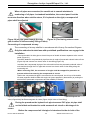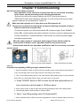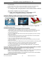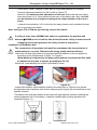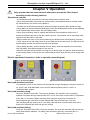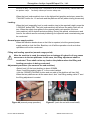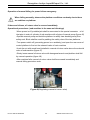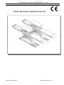
1
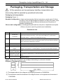
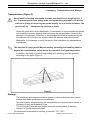
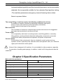
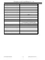
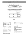
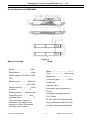
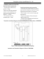
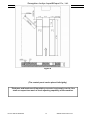
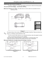
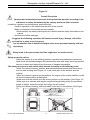
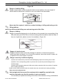
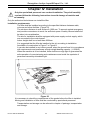
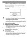
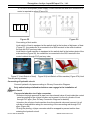
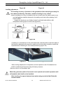
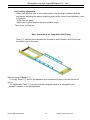
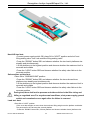
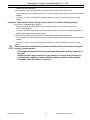
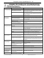
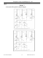
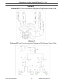
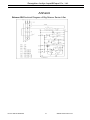
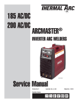
Guangzhou Junliye Import&Export Co., Ltd.
Tubular Big Scissor Hydraulic Auto Lift
Phone: 0086-20-86394322
1
Website:www.431tool.com
Guangzhou Junliye Import&Export Co., Ltd.
User’s Manual
Manufacturer and Facilitator
Scissor Hydraulic Lifter for Vehicles
Model:
Manufacturing code:
Manufactured on:
DD
MM
YY
Manufacturer:
Authorized Distribution Center
Phone: 0086-20-86394322
2
Website:www.431tool.com
Guangzhou Junliye Import&Export Co., Ltd.
Content
User’s Manual..................................................................................................................... 2
Manufacturer and Facilitator.............................................................................................2
Packaging, Transportation and Storage......................................................................... 4
Introduction of User’s Manual.......................................................................................... 6
Chapter I: Description of Machine................................................................................... 8
Chapter II Specification Parameters............................................................................... 9
Chapter III Safety..............................................................................................................16
Chapter VI Maintenance and Care................................................................................37
Phone: 0086-20-86394322
3
Website:www.431tool.com
Guangzhou Junliye Import&Export Co., Ltd.
Packaging, Transportation and Storage
All the operations such as packaging, handling, transportation and
dismounting shall be operated by specialized technicians.
Packaging and transportation
Packaging (Figure 1)
Standard configuration: oil pipe and accessories (1# box) one piece, control panel (2 # box)
one piece, front and back baffle and support (3 # box) one piece, main
and auxiliary beam (4# and 5# box) two pieces and five pieces of
standard configurations.
Choose and configuration: mounting guide plate (6# box) one piece, trapezoidal cover plate
(7# box) one piece (used for ground mount installation).
Encasement List
CaseNo.
1
2
Name
Oil pipe and
accessories
(Control cabinet)
Name and quantity of accessories
① 22 sets of foundation bolts; ② Four pieces of foamy cushions (plat large scissor type
never gets involved in such item) ③ One copy of User’s Manual ④ 4 pieces ofφ14
composite washer ⑤ 10 pieces of bandage (250 mm long)
All the joints of gas pipe are in the control cabinet, with gas cylinder, joints at the gas
cylinder and four pieces of pipes excluded (gas cylinder, joint of gas pipe and gas pipes
have already been installed in the machine)
3
Main beam (1 P)
4
Auxiliary beam (2P)
5
6
7
① Gas pipe and joint of gas pipe ②Limit switch ③Oil pipe all are installed in the machine
The same as above
Front and back baffle and
① Two pieces of front baffle and support; ② 2 pieces of dual front and back baffle and
support
support ③Four pieces of ¢3.2x35 split pins ④ Two pieces of back baffle and support.
Mounting guide plate
(selective configuration)
Trapezoidal cover plate
(selective configuration)
Date
2
① One piece of 1800 mm long; ② One piece of 950 mm long;③ One piece of 750 mm
long
Inspectorofencasement
Figure 1 Note: Box 6 and box 7 are configured according to customers’ demand.
Diagram of Packaging Dimension:
Figure 1
(1) The diagram above is the diagram of packaging dimension of CW835WA,
(2) The dimension inside the brackets in the diagram above is the appearance dimension of
CW835WA+
Phone: 0086-20-86394322
4
Website:www.431tool.com
Guangzhou Junliye Import&Export Co., Ltd.
Packaging, Transportation and Storage
Transportation (Figure 2)
Goods shall be handled and moved by crane and fork lift truck weighing over 3
ton. To prevent goods from falling down, during the lifting operation, one person
shall be in charge of observing the goods intently, so as to avoid accidents. The
goods shall be
transported by vehicles or liners.
When the goods arrive at the destination, it is necessary to check whether the goods
are complete to prevent damage and loss during the transportation. If there is any
damage in the package, inspection to the damaged box shall be conducted by the
Encasement List to confirm the situation about the damage and loss of goods.
Meanwhile, it is necessary to notify the person that undertakes the transportation
immediately.
The machine is heavy goods! Manual loading, unloading and handling shall be
beyond the consideration, safety during the operation is of great importance.
In addition, the lifting of goods during loading and unloading shall be operated
according to the figure (Figure 2)
Figure 2
Storage:
The machinery and equipment shall be placed in indoor warehouse and outdoor
storage shall make good water-proof treatment.
Van truck shall be adopted during the transportation and goods shall be stored in
containers if they are shipped by liners.
The control panel shall be kept upright during the transportation; in addition,
extrusion of goods shall be avoided.
Environmental temperature for storage of machine: -25℃~55℃.
Phone: 0086-20-86394322
5
Website:www.431tool.com
Guangzhou Junliye Import&Export Co., Ltd.
Introduction of User’s Manual
This manual is intended for operators of vehicle maintenance enterprise and
routine maintenance personnel.
Before the lifter is operated, relevant personnel shall carefully read the User’s Manual.
There is important relevant information in the manual:
-Personal safety of operators and maintenance personnel
-Safety in installation
-Safety operation of lifter
Please keep this manual
This manual is an important part of the lifter
The manual shall be place around the lifter, so that the operator and maintenance
personnel can read it at any time
Please carefully read Chapter III, which contains important information on application
and safety
The lifter is designed and manufactured by European Standard
Loading and unloading, transportation, dismounting, assembling,
commissioning and testing; specially the maintenance, repair, overhaul,
transportation and dismounting of lifter shall executed by professionals with
license.
Injury of human and damage of the machine caused by operation of no-authorized
personnel or operation not in accordance with the operating rules occur, the
manufacturer bears no liability for this.
The manual suggests: operation and safety is guarantee for operator and
maintenance personnel. To better understand the structure and operating rules of
the machine, please carefully read the User’s Manual before you use the
machine.
To better understand the terms in the manual, operator shall possess experience on
service at factory, maintenance and repair, etc. and can read the explanations in
drawings and the manual and relevant special national safety ordinance on
equipment installation.
This is also applicable to maintenance and the maintenance personnel shall possess
special knowledge on machinery engineering
-Operator: Personnel that have been trained and authorized to use the lifter
-Maintenance personnel: Routine maintenance personnel that have been trained and
authorized
Phone: 0086-20-86394322
6
Website:www.431tool.com
Guangzhou Junliye Import&Export Co., Ltd.
The manufacturer keeps the right of the minor modification of the manual due to
advancement of technology
Phone: 0086-20-86394322
7
Website:www.431tool.com
Guangzhou Junliye Import&Export Co., Ltd.
Chapter I: Description of Machine
Machine
Scissor Hydraulic Lifter can lift vehicles weighing no more than 3500 kg. They are applied
in test and measurement of four-wheel positioning of vehicles of various grades in vehicle
maintenance enterprise and tire distributor, overhaul, maintenance and care of vehicles.
Structural characteristics:
-The machine adopts concealing scissor structure with small occupation
area
-With independent control cabinet and low-voltage control, the safety
performance of the machine is excellent
-The machine possesses safe testing device that can lower and hoist
claw to unlock
-With hydraulic capacity synchronous oil cylinder, the operation of
platform is synchronous and stable
-With double safety devices of hydraulic lock and mechanical
double-tooth safety claw, the machine can automatically open. By
operation of locking, reversed positioning of the safety claw can be
realized. It is safe and reliable.
-The machine possesses hydraulic failure and overloading safety valve
protection
-The machine possesses control device at oil way, thus, when the oil
pipe cracks, the machine will not rapidly fall
- The machine adopts super wear-resistance sliding block for oil-feeding
-The machine adopts good quality hydraulic and electric components
from Italy, Germany and Japan, etc.
- The machine adopts an integrated base, which makes a strong
Phone: 0086-20-86394322
8
Website:www.431tool.com
Guangzhou Junliye Import&Export Co., Ltd.
horizontal adjusting ability and the horizontal precision can be accurately
adjusted, this is especially suitable for four-wheeled fixed position testing
-The machine possesses emergency manual lowering device when
there is a power failure
The normal lifting of vehicles requires the following conditions for devices
-Foundation of machine (position for equipment installation and space)
-Frame of lifter (main structure of lifter and safety mechanism)
-Control cabinet (control part of the machine)
Basic structure
The foundation of machine is composed by concrete structure and it is suggested
that angle steel protection be set around the pit.
Frame of lifter
It is composed by solid steel connecting leveler, main lifting platform, secondary
lifting platform, prolonged back-wheel side sliding plate components, pneumatic
double-tooth safety components and hydraulic oil cylinder components.
Control cabinet
At the bottom of the control panel, there is a hydraulic control system such as
hydraulic oil tank, hydraulic pump, hydraulic motor and hydraulic valve, etc. While the
upper part is electrical control system
Scissor Lifter is designed to lift vehicles. It is not suitable for other occasions, especially
for operation of washing and spraying. In addition, it shall not lift things heavier than the
rated load.
Chapter II Specification Parameters
Main technical parameters:
Model
CW830WA
Driving method
CW830WA+
Electro hydraulic
Rated lifting weight of host
3500kg
Rated lifting weight of sub-machine
3500kg
Hoist height of host
Hoist height of sub-machine
Original height of platform
Length of platform of host
Length of platform of sub-machine
1800mm
420mm
330mm
Phone: 0086-20-86394322
4000mm
4500mm
1400mm
1850mm
420mm
9
Website:www.431tool.com
Guangzhou Junliye Import&Export Co., Ltd.
Width of platform of host
625mm
Width of platform of sub-machine
570mm
Lifting time of host
≤60s
Falling time of host
≤60s
Lifting time of sub-machine
≤20s
Falling time of sub-machine
≤30s
Total width of platform of the whole machine
About 2070mm
about
Aboutnone
4500 mm
Total length of the whole machine
Weight of the whole machine
Power supply
Power of the whole machine
Hydraulic oil
Pressure of air supply
Temperature of working environment
Humidity of working environment
About 1600kg
none
AC 400V or 230V±5% 50Hz
2.2kw
The same as that of 20# wear-resistance hydraulic
oil (user prepares it by himself/herself)
201 The same as that of 20# wear-resistance
hydraulic oil (user prepares
6-8kg/cmit2 by himself/herself)
5-40℃
30-95%
Noise of machine
< 76db
Height of installation of machine
Altitude≤1000M
Temperature for storage of machine
-25℃~55℃
Table 2
Phone: 0086-20-86394322
10
Website:www.431tool.com
Guangzhou Junliye Import&Export Co., Ltd.
Overall dimension of CW830WA
Figure 3
Motor of oil pump:
Model………………………Y90L
Rated power……………… 2.2kw
Rated voltage…AC 400 or 230V
±5%
Rated current………… 400V:5A
………………230V:10A
Rated frequency……………50Hz
Limit No. ………………… 4
Rotating speed……1450rpm/min
Connecting form………… B14
Insulation class…………………F
The connecting of motor is
indicated in the diagram, the
direction of motor is clockwise
(see from top to bottom)
Phone: 0086-20-86394322
Pump:
Model…………………………P4.3
Type……………………Gear pump
Rated flow……………4.3cc/r
Connecting type……………Direct
connection
Overflow valve
Successive working pressure…
210bar
Intermittent working pressure…
150~300bar
Fill 18 L that is the same as 20#
wear-resistance hydraulic oil into
oil tank of the pump station that
11
Website:www.431tool.com
Guangzhou Junliye Import&Export Co., Ltd.
Overall dimension of CW830WA+
Motor of oil pump:
Model………………………Y90L
Rated power……………… 2.2kw
Rated voltage…AC 400 or 230V
±5%
Rated current………… 400V:5A
………………230V:10A
Rated frequency……………50Hz
Limit No. ………………… 4
Rotating speed……1450rpm/min
Connecting form………… B14
Insulation class…………………F
The connecting of motor is
indicated in the diagram, the
direction of motor is clockwise
(see from top to bottom)
Phone: 0086-20-86394322
Figure 4
Pump:
Model…………………………P4.3
Type……………………Gear pump
Rated flow……………4.3cc/r
Connecting type……………Direct
connection
Overflow valve
Successive working pressure…
210bar
Intermittent working pressure…
150~300bar
Fill 18 L that is the same as 20#
wear-resistance hydraulic oil into
oil tank of the pump station that
12
Website:www.431tool.com
Guangzhou Junliye Import&Export Co., Ltd.
Installation scheme of scissor lifter
Attention: Basic requirements
- Concrete type is 425#, the dry
Provide the following at the same time:
period is 15 days
-Preliminarily bury the pit between the control
-Remove the internally generated
panel and the foundation pit and the PVC pipe
surface in the foundation pit, the
between the two pits that is no more than
thickness of concrete at the pit
100mm length, so as to connect oil pipe, gas
bottom is ≥150mm
pipe and wire.
-The levelness of the two
-Connect to the power of the control panel
foundation pit is ≤5mm
(400V or 230V 15 A)
-Connect to the compressed air inlet tube on
the control panel (Ф8×5mm)
Foundation Installation Diagram of Tubular dual Big Scissors Lifters Series of CW830WA
Figure 7 (The control panel can be placed left-rightly)
Installation and Foundation Diagram of Lifters of CW830WA+
Phone: 0086-20-86394322
13
Website:www.431tool.com
Guangzhou Junliye Import&Export Co., Ltd.
Figure 8
(The control panel can be placed left-rightly)
Thickness and levelness of foundation concrete is extremely crucial. One
shall not expect too much of level adjusting capability of the machine.
Phone: 0086-20-86394322
14
Website:www.431tool.com
Guangzhou Junliye Import&Export Co., Ltd.
Vehicle type that the lifter is suitable for:
This lifter is applied to vehicles with weight and dimension within the following data:
The maximum hoist weight: no more than 3500 kg
Maximum dimension of vehicle: The table below is used to define the standard of limit in
operating of lifter
CW830WA/
CWA830WA+
Min
A 1900
B 100
C
D 900
Figure 9
The lower bottom of the vehicle may collide with parts of the lifter. When one drives the
vehicle, one shall pay special attention to this.
The lifter can also hoist ordinary or non-standard vehicles, when the weight of vehicle
does not exceeds the maximum hoist capability
There shall also be different definition of dimensions in personnel safety area
Inspect the maximum load and the possible maximum limit of imbalance
Maximum distribution of weight during the hoisting of vehicles
Figure 10
Phone: 0086-20-86394322
Figure 11
15
Website:www.431tool.com
Guangzhou Junliye Import&Export Co., Ltd.
Chapter III Safety
There is important content in this chapter. Operators shall carefully read this
chapter.
The following content is explanation and description about danger and the possible
danger during the operation, the correct effect and description of safety devices of
equipment, other dangers, correct operating rules and potential dangers, etc.
The designing and manufacturing of lifter is intended for hoisting and
maintenance of vehicles. It is inappropriate for the hoisting of other goods. It is
suitable especially for the following operation:
-Washing and cleaning of vehicles
-The hoisting operation where there are persons on the platform
-The hoisting operation of goods in bulk or broken goods
-It is applied as the elevator
-It is applied in vehicles with severely tilt frame or severe deformed tire
The manufacturer bears no liability for personal injury or loss of property caused by
incorrect operation or operation that violates the operating rules.
During the falling, operator shall operation within the safety area shown in the
diagram.
As is shown in the diagram, operations by operator or other irrelevant personnel
within this dangerous area are strictly forbidden.
Only when the vehicle is completely hoisted to the required position and the
operation platform becomes still and the safety devices of the machine is completely
prepared (such as the insurance gear is fully locked), can the operator and
maintenance personnel be permitted to conduct operation under the vehicle.
Lifter shall never be used when there are no safety protection devices.
The might be casualty of personnel, damage of machine and damage of the
vehicle that is to be hoisted if the operating rules mentioned above are not
observed.
Phone: 0086-20-86394322
16
Website:www.431tool.com
Guangzhou Junliye Import&Export Co., Ltd.
Figure 12
Overall Prevention
Operator and maintenance personnel shall operate the machine according to the
ordinance on safety formulated by the country where the lifter is located.
In addition, operator and maintenance personnel shall:
-Conduct operation in the safety area required in the manual
-Make no alteration of the safety devices casually.
-Read carefully the safety warnings on the machine and the safety information in the
manual
-Here are the safety warnings:
Suggests the following operation will cause personal injury, damage of the lifter
and vehicle or other loss of property.
It is the situation that is unsafe and might cause more personal casualty and loss
of property.
Safety mark in the place where the lifter might have an electric shock
Safety protection device
When the vehicle is on the hoisting platform, operator and maintenance personnel
shall check the possible danger, the manufacturer also shall adopt various protection
devices to avoid and reduce the occurrence of dangers as possible.
The safety of personnel and vehicle shall operate according to the following rules:
-When the vehicle-hoisting, operator and maintenance personnel shall never enter
the non-safe working area (Figure 12, in the lower part of the machine and the
vehicle)
-When the vehicle is placed on the platform, the engine of the vehicle shall be turned
off and the brake shall be pulled tightly.
-Make sure that the vehicle is at the correct position on the platform (See Figure 13)
-Make sure only vehicles with weight, height and length being within the permitted
scope of weight, maximum height and length can be hoisted.
During the vehicle-hoisting, personnel shall never stay on the platform (See Figure
13)
Phone: 0086-20-86394322
17
Website:www.431tool.com
Guangzhou Junliye Import&Export Co., Ltd.
Figure 13
The potential dangers during vehicle-hoisting:
The following safety devices are intended for protecting overloading or mechanical
failure protection:
Under the situation of overloading, the overflow valve at the pump station will open and
return oil into the oil tank (See Figure 14)
Bottom of each oil cylinder is equipped with flow control valve. When some oil pipes
crack in hydraulic circuit, the flow control valve will work and limit the speedy sliding
and falling of the platform (See Figure 15)
Figure 14(Overflow valve)
Figure 15 (Flow control valve)
Safety rack and gear and rack set of host guarantees personnel under the machine
when other protection measures fail. It is necessary to make sure the safety gear and
rack set is of perfect occlusion and the integrality of safety gear and rack set is good.
(Figure 16)
Function of sub-machine safety claw is the same as that mentioned above. (Figure
17)
Figure 16 (Safety of Host)
Figure 17 (Safety of Sub-machine)
When the host is hoisted to the required height, Button “locking” shall be
operated. Make sure that the safety claw and the safety rack are firmly fastened,
following that one can operate under the machine and there shall be no rarity on
the safety components.
Danger of personnel
This item suggests: the possible potential danger due to incorrect operation of
operator and maintenance personnel any other personnel within the working area.
Danger of extrusion
Phone: 0086-20-86394322
18
Website:www.431tool.com
Guangzhou Junliye Import&Export Co., Ltd.
Danger caused by personnel’s failure in leaving the area mentioned above according
to the rules when the lifter is hoisting or falling.
No personnel can work under the moving parts of the machine when the lifting
platform is hoisting or falling. Personnel shall stay in safety position. (Figure 18)
Danger of impact
Operator can conduct hoisting and falling of the lifter when he/she has confirmed that
there are no personnel within the dangerous area. Meanwhile, when the lifter is at a
rather low height (less than 1.75 meter from the ground), since there is no color on
the machine, impact of collision of personnel due to no color on the machine, shall be
avoided. (Figure 18)
Figure 18
Danger of personnel falling down
There shall be no personnel on the lifting platform or inside the vehicle that is to be
hoisted when the lifter is hoisting or falling, so as to prevent them from falling. (Figure
19)
Figure 19
Danger of vehicle-moving:
Danger cause by forcefully moving the vehicle, it is necessary to make sure that the
brake of the vehicle is completely fastened. (Figure 20)
Phone: 0086-20-86394322
19
Website:www.431tool.com
Guangzhou Junliye Import&Export Co., Ltd.
Figure 20
Danger of vehicle-falling:
Danger caused when vehicle is placed at the incorrect position, the over-weight of
vehicle and the dimension of vehicle is not in accordance with standards.
Figure 21
Never start the engine of vehicle to conduct hoisting or falling and testing on the
lifting platform.
Never lay articles at the falling area and moving parts of the lifter.
Danger of sliding:
Danger of personnel slipping due to oil pollutant on the ground in the surrounding of the
lifter, the lower part of the lifter or the surrounding area and platform shall be clean. If
there is oil pollutant, please remove it immediately. (Figure 18)
Figure 22
Danger of electric-shock:
Danger of electric shock caused by damage of insulation of electrical equipment
Never use water and steam, etc. to clean the machine, never use solvent or paint, etc.
to approach the control panel of the lifter.
Danger caused by insufficient lighting:
Operator and maintenance personnel shall install lighting required for working area of lifter
operation in the corresponding position to prevent loss of parts and personal danger due to
insufficient light.
Operator shall constantly observe the lifter and conduct operation within the position of operator
due to hoisting and falling.
Rubber cushion shall be placed under the chassis when the sub-machine is hoisting and falling.
Never move the safety devices
Hoist weight shall not exceed the maximum hoist capability required for the
machine and make sure that the machine is not over-loaded.
It is necessary to operate according to the rules in the manual on using, maintenance
Phone: 0086-20-86394322
20
Website:www.431tool.com
Guangzhou Junliye Import&Export Co., Ltd.
and safety, etc.
Phone: 0086-20-86394322
21
Website:www.431tool.com
Guangzhou Junliye Import&Export Co., Ltd.
Chapter IV Installation
Only the specialized personnel can conduct installation. They shall carefully
read and follow the following instructions to avoid damage of machine and
personnel casualty.
Only the authorized technicians can install the lifter.
Installation requirements:
The lifter shall be installed according to the specified distance between walls,
columns and other facilities. (Figure 23)
The minimum distance to wall surface is 1000 mm. To prevent against emergency
and provide convenience to work, the sufficient space of safety channel shall also
be taken into consideration.
The site for installation shall be equipped with power supply and air supply, which
are connected to the control panel.
Indoor height shall be no less than 4000mm.
It is suggested that the lifter be installed in the pit, according to installation
foundation of construction in Figure 7 or Figure 8.
It can also be installed in any indoor ground, when the ground level is in accordance
with requirements and possesses enough weight bearing capacity. (≧250KG)
When the machine is to be installed, there shall be enough light to guarantee the
safe operation of commissioning and maintenance and avoid the eyestrain of
personnel caused by stimulated light.
Figure 23
It is necessary to check the completeness of the goods before the lifter is installed.
Moving and installation of lifter shall be conducted by specialized personnel.
Transportation and storage can be referred to chapter of package, transportation
and storage.
Phone: 0086-20-86394322
22
Website:www.431tool.com
Guangzhou Junliye Import&Export Co., Ltd.
Installation of lifting platform
The groove of the rotary table of the platform is at the front of the vehicle-mounting
direction, the side plate of platform with yellow and black stripes is outside the
machine.
When the lifter is installed in the pit or the ground, adjusting cushion iron shall be
inserted at the bottom of the platform.
Fork lift truck or other hoisting equipment hoists the lifting platform (Figure 24); to
hoist it to the height of about 1000MM to ensure that the safety device of the machine
is on and locked.
Figure 24
To avoid failure of safety device of the machine, one wooden block can be
inserted between the connecting rod.
Never work under the lifter when hydraulic system is not fully filled with
hydraulic oil and there is hoisting and falling.
Move the lifting platform, adjust the distance between the two platforms and make
sure the two platforms are in parallel position.
Conduct connecting of electric circuit, oil-way and air-way according to Electrical
Connection Diagram and Oil-way Connection Diagram.
The connecting of air-way can be conducted only after the connecting of the
hydraulic system has been completed.
Oil pipe, wires and air pipe shall never be damaged.
During the procedure the oil pipe and air pipe is traversing into the pit through
the PVC pipe from the control panel, protection of connectors shall b given
special attention to prevent rarities from entering the oil-way and air-way
and damaging the hydraulic system.
Electric circuit connection:
Electric circuit shall be connected in accordance with wire diameters and wire
number specified in Electrical Connection Diagram.
Electric mounting operation shall be only carried by professionals with electric
operation qualification.
-Open upper cover of control cabinet
- Power cord connection: connect 400V three-phase four-wire system power cord
(3×2.5mm2+1×1.5 mm2 cable) to control panel L1, L2,L3 and incoming terminals;
Connect PE ground wire to stud with grounding sign (Figure 25) and stud with
grounding sign provided at the bottom of two platforms.
Phone: 0086-20-86394322
23
Website:www.431tool.com
Guangzhou Junliye Import&Export Co., Ltd.
-If it is 230V three-phase power supply, control transformer and wire connection of
motor is required to adjust (Figure 26)
L1 L2 L3 P
E
Figure 25
Figure 26
Connecting of limit switch
Limit switch of host is equipped at the switch shelf at the bottom of big beam of host
(Figure 27), the conductor is connected to the SQ2 terminal in the control cabinet
through the PVC pre-bury tube;
Limit switch of sub-machine is equipped at the switch shelf at the bottom plate of the
sub-machine (Figure 28), the conductor is connected to the SQ1 terminal in the
control cabinet through PVC pre-bury tube;
2
Figure 27 (Limit Switch of Host) Figure 28 (Limit Switch of Sub-machine) Figure 27A (Limit
Tubular plat big scissor)
Connecting of hydraulic circuit
Connect hydraulic oil pipes according to Oil-way Connection Diagram.
Only authorized specialized technicians can engage in the installation of
hydraulic circuit.
Pay special attention to oil pipe connector.
-Introduce the high-pressure oil pipe from the solenoid valve of host inside the control
panel according to the oil pipe number and connect it to the oil cylinder of host
through PVC pipe. (See Oil-way Connection Diagram for details)
-Introduce the oil pipe of sub-machine from the solenoid valve and connect it to oil
cylinder of sub-machine along the connecting of the connecting rod through PVC
pipe. (Figure 29)
-During the placing, oil pipe connector shall be wrapped to prevent rarities from
entering the hydraulic circuit.
Phone: 0086-20-86394322
24
Website:www.431tool.com
Guangzhou Junliye Import&Export Co., Ltd.
When oil pipes are connected, be careful not to commit mistakes in
numbering of oil pipes. In standard installation, the control panel is at the
left of the direction when vehicle enters, if it is placed on the right, correspond oil
pipes shall be adjusted.
Figure 29 (oil pipe goes through the cap)
Figure 30 (The flat big scissor never
gets involved in the secondary lifting oil tube)
Connecting of compressed air-way:
The connecting of air-way shall be in accordance with Air-way Connection Diagram.
Only the authorized technicians with specialized qualifications can engage in the
installation.
-Connect theΦ8×5 air inlet pipe to the air inlet port of double oil-water separator at the control
panel (Figure 31)
-Introduce theΦ6×4 compressed air pipe from the air outlet of pneumatic solenoid valve of host
(Figure 32) and connect it to the air valve of claw-lifting (Figure 33)
-Introduce the compressed air pipe of the sub-machine from the pneumatic solenoid valve of
sub-machine through the PVC pipe and connect it to the air valve of claw-lifting along the
connecting rod.
-When traversing PVC, the connector of air pipe shall be wrapped for protection to
prevent rarities from entering the compressed air circuit.
-Before the compressed air pipe is connected to the control panel, the oil cup of the double
oil-water separator shall be filled with engine oil (users prepare by themselves) to prolong the
service life of pneumatic components and the reliability of actions.
Figure31 (Double Oil-water Separator) Figure32
(Electromagnetic Air
Valve) Figure32A (Plat Electromagnetic Air Valve) Figure 33(Air Valve of Claw-lifting)
During the procedure the hydraulic air pipe traverses PVC pipe, air pipe shall
not be folded and knotted to avoid unsmooth air circuit or blockage of air
circuit.
Before the compressed air inlet pipe is introduced to the air inlet of the
Phone: 0086-20-86394322
25
Website:www.431tool.com
Guangzhou Junliye Import&Export Co., Ltd.
pneumatic solenoid valve inside the control panel, the double oil-water
separator shall be filled with engine oil to conduct separation treatment to
the compressed air to avoid failure of actions of pneumatic unit.
Phone: 0086-20-86394322
26
Website:www.431tool.com
Guangzhou Junliye Import&Export Co., Ltd.
Chapter V Commissioning
Add oil and check phase sequence:
After hydraulic circuit, electrical circuit and air-way are connected according
to the annex, operate according to the following procedures:
-Remove the cover of the control cabinet and fill 18 L that is the same as
“ESSO-NUTO H20” wear-resistance hydraulic oil to the oil tank with funnel (users
prepare hydraulic oil by themselves). Figure 34
Make sure the hydraulic oil is clean when one fills hydraulic oil,
To prevent any rarity from entering the oil-way and causing unsmooth oil-way or
failure of actions of solenoid valve.
-Connect the power, turn off the total switch QS of power supply, Press “RISING”
button SB1, check whether the rotation direction of motor is correct (rotating from top
to down clockwise). If reversal direction is discovered, cut down the power supply
and adjust power phase.
After the power supply is connected, high-voltage electric shock inside the
control panel is likely to occur. Operation shall be only carried out by
professionals with electric operation qualification and it is necessary to prevent
electric shock.
Figure 34 (Oil Tank)
Figure 35 (Pump Valve Diagram)
Figure 35A (Flat Pump Valve
Diagram)
Procedure for adjusting of filling and gas exhaust of host:
1. Place the switching switch of the host and sub-machine at the control panel to SA position of
“host” (The flat big scissor never gets involved in SA change-over switch).
2. Turn off “host filling-ending valve G” and “Sub-machine filling-ending valve H” (anti-clockwise
90º) Figure 35; The flat big scissor closes “oil cutoff valve F for the host”
3. Press “RISING” button of SB1 to hoist the left and right platforms of
host (view from vehicle head) to 1000mm about.
4. Press “down” button of SB2 to make the left and right platforms fall to the lowest position.
5. Left and right platform shall be lifted to 1400mm about.
6. Open “ host filling-ending valve G”(clockwise90°).
7. Press “RISING” button of SB1 to hoist the right platform of host to 1000mm about (view from
Phone: 0086-20-86394322
27
Website:www.431tool.com
Guangzhou Junliye Import&Export Co., Ltd.
the vehicle head).
8. Press “down” button of SB2 to make the right platform of host fall to the lowest position.
9. Repeat the step pf 7 and 8 for 5-6 times and air shall be exhausted automatically.
10. Finally press SB1, the right platform of host shall be lifted to 1400mm
about (both of platforms are equal in height).
11. Close “ host filling-ending valve G” in anticlockwise of 90°.
Regulation of filling and exhausting for host ends.
Inspection: Whether the safety claws of the two hosts keep flexible and reliable
movement and whether there exists leakage in the oil-way and gas-way
Figure 36 (sub-machine limit switch)
Figure 37 (host limit switch) Figure 37A
( Flat big scissor limit switch)
Procedure for filling oil and releasing gas of the sub-machine
1. Place the switch SA for changing host and sub-machine on the control panel to
“SUB-MACHINE” position (The flat big scissor never gets involved in SA change-over switch)
2. Shut “host filling-ending valve G” and”sub-machine filling-ending valve H” (turn 90º
counterclockwise) Figure 35
3. Press the “RISING” button SB1 and lift the sub-machine right platform (see form the vehicle
head) to about 300mm
4. Press the “FALLING” SB2 and lower the sub-machine right platform to the lowest position
5. Lift the sub-machine right platform to about 400mm
6. Open “sub-machine filling-ending valve H” (turn 90º clockwise)
7. Press the “RISING” button SB1 and lift the sub-machine left platform (see from the vehicle
head) to about 300mm
8. Press the “FALLING” button SB2 and lower the sub-machine left platform to the lowest position
9. Reap the steps in Item 7 and 8 for 5-6 times and conduct automatic air-releasing
10. Finally, Inch SB1 and lift the sub-machine left platform to about 400mm (90º)
11. Turn 90º counterclockwise to shut “sub-machine filling-ending valve”. The oil-filling and
gas-releasing adjustment is ended
Inspection: Whether the safety claws of the two sub-machines keep flexible and reliable
movement and whether there exists leakage in the oil-way and gas-way
Adjustment of sub-machine limit switch:
-Place SA to “SUB-MACHINE’ position. Press SB1 to lift the sub-machine platform to
450mm. conduct adjustment and limit for SQ1 (refer to Figure 36)
-Lower the sub-machine platform. Lift it to 450mm for many times to verify whether
the sub-machine limit is accurate and reliable
Adjustment of host limit switch:
Phone: 0086-20-86394322
28
Website:www.431tool.com
Guangzhou Junliye Import&Export Co., Ltd.
-Place SA to “HOST’ position. Press SB1 to lift the host platform to 1,850mm.
Conduct adjustment and limit for SQ1 (refer to Figure 37)
Attention: the maximum limit adjustment of the host shall make the host safety
claw stop where it is 5-10mm above the last rack of the safety rack. Also, the limit
can be adjusted at any height according to the height situation of the user’s
house
-Lower the host platform. Lift it to the limit for many times to verify whether the host
limit is accurate and reliable
Note: see figure 37A of Tubular type flat big scissor limit switch
If ceiling is lower than 4000MM, limit switch is regulated to the position with
distance≦200MM of roof of vehicle after hoisted from the ceiling in order to avoid
damaging vehicle and guarantee the safety of vehicle and person.
Installation of foundation bolt:
The construction of foundation bolt shall be undertaken after the expiration of
maintenance for concrete. Otherwise the strong quality shall be affected.
-Adjust the left and right platform in alignment and the distance of the two platforms
according to the requirements of figure 7 or figure 8.
-Metal backing is adjusted by the base pad of platform to prevent the lifter shall
be adjusted levelly due to uneven ground(figure 38, 39)
Attentions: metal backing iron shall be provided by users.
Figure 38
Figure 39
- Impact drill hammer ofΦ18 shall be drilled to the deep hole of 120mm from ground
through base hole of platform with electric hammer pinch (figure 40) and entrance to hole
shall be cleaned.
-Foundation bolt shall be installed in the holes with light hammer (without installing the
central expansion nail of foundation, it shall be installed after leveling adjustment is
completed (figure 41).
Phone: 0086-20-86394322
29
Website:www.431tool.com
Guangzhou Junliye Import&Export Co., Ltd.
Figure 40
Figure 41
Leveling adjustment:
The leveling accuracy of machine is the guarantee of the detecting accuracy for
four-wheel positioning. Therefore, machine leveling is very critical.
-When the platform of host is hoisted to the fifth or sixth rack, the safety claws of left
and right platform shall be fastened in the safety rack chain after pressing “lock”
button of SB3.
- Inspect the levelness on all sides of plan for left and right platform with
transparent leveling pipe or level-mete (figure 42)
Figure 42
-If platform is unleveled due to the unleveled base, adjusting bolt in the base plate of
host shall be adjusted with wrench to make the level accuracy of platform reach the
requirements of detecting for four-wheel positioning (figure 43)
Figure 43
Figure 44
-After leveling adjustment is completed, central expansion nail of foundation bolt
shall be installed and hammered by with heavy hammer.
-Screw on the nut of foundation bolt
When the guarantee period of concrete is not expired and central expansion nail
of foundation bolt shall not be installed.
After leveling, the space between base plate and ground shall be filled with
cement mortar.
Phone: 0086-20-86394322
30
Website:www.431tool.com
Guangzhou Junliye Import&Export Co., Ltd.
Low leveling adjustment:
When main platform falls to the lowest position, low leveling of platform shall be
adjusted by adjusting the support adjusting screw at the lower of main platform ( refer
to figure 44).
-Undo fixed nut firstly.
-Adjust the length of support screw to suitable length.
-Then screw on fixed nut.
Note: Instructions for Foundation Bolt Fixing
Parts ①② shall be removed when the foundation bolt is fixed so as to fix the rest
foundation bolt on the base.
Main functions of Parts ①②:
(1) Firstly, Parts ①② can fix two bases so as to facilitate the client to fix the position of
the lift
(2) Additionally, Parts ①② prevent that the complete machine is damaged by the
transport machine in the transportation.
Phone: 0086-20-86394322
31
Website:www.431tool.com
Guangzhou Junliye Import&Export Co., Ltd.
Host NO-load teat:
-Connect power supply switch QS, place SA to “HOST” position and shut “host
filling-ending valve” and “sub-machine filling-ending valve”
-Press the “RISING” button SB1 and observe whether the two hosts’ platforms rise
steadily and simultaneously
-Lift the platforms to the highest position and observe whether the maximum limit is
accurate and reliable
-Press the “LOCK” button SB3 and observe whether the safety claw falls onto the
accurate position
Sub-machine on-load test:
-Place SA to “SUB-MACHINE” position
-Press the “RISING” button SB1 and observe whether the two sub-machines
platforms rise steadily and simultaneously
-Lift the platforms to the highest position and observe whether the maximum limit is
accurate and reliable
-Press the “LOCK” button SB3 and observe whether the safety claw falls onto the
accurate position
During test, there shall not be persons and other articles in the lifter rising and
falling or regulated area. For any abnormal conditions, shut power supply general
switch and commission once again after the failure is removed
Load test: host
-Place SA to “HOST” position
-Drive a car that weighs not more than the maximum lifting weight onto the platform and brake.
The personnel in the car leave the car and platform
--Press the “RISING” button SB1, lift host platform and observe whether hosts’ platforms rise
Phone: 0086-20-86394322
32
Website:www.431tool.com
Guangzhou Junliye Import&Export Co., Ltd.
steadily and simultaneously
-Inspect whether lifter frame and hydraulic pump station produce abnormal sound
-Lift the platforms to the highest position and observe whether the maximum limit is accurate and
reliable
-Press the “LOCK” button SB3 and observe whether the safety claw falls onto the accurate
position
Load test: sub-machine (Note: flat big scissor does not need the following steps)
-Place SA to “SUB-MACHINE” position
-Place jacking glue cushion where it is the jacking position of the vehicle bottom on the
sub-machine platform
-Press the “RISING” button SB1, Lift sub-machine platform and observe whether sub-machine
platform rises steadily and simultaneously
-Inspect whether lifter frame and hydraulic pump station produce abnormal sound
-Lift the platforms to the highest position and observe whether the maximum limit is accurate and
reliable
-Press the “LOCK” button SB3 and observe whether the safety claw falls onto the accurate
position
During test, there shall not be persons and other articles in the lifter rising and
falling or regulated area.
The weight of tested vehicle can not exceed the minimum lifting capacity of
the lifter
Inspect whether there exists oil or gas leakage in oil-way and gas-way. For
any abnormal conditions, shut down the machine timely and commission
once again after the failure is removed
Phone: 0086-20-86394322
33
Website:www.431tool.com
Guangzhou Junliye Import&Export Co., Ltd.
Chapter V Operation
Only operator that has been trained is allowed to operate the lifter. Inspect
according to the following cautions
Operational cautions
-The obstacle around and below the machine shall be removed before work
-During rising and falling, there shall not exist persons in the regulated area for the lifter, below
the machine and in the vehicle on the platform
-The lifter can not lift vehicles and other goods that weighs beyond the lifter operation scope
-During lifting, the vehicle shall be braked tightly. Place anti-skidding device such as anti-skidding
corner blocks under the tier (which the user shall provide)
-During rising and lifting, observe whether the platforms are simultaneous all the time. If
abnormal conditions are found, stop the machine at once. The machine can be used again after
inspection and the failure is removed
-When maintain and care or four-wheel positioning for detection and commissioning, press the
“LOCK” button to lock the safety claws of the two platforms at the same level. The personnel can
operate below the lifter and vehicle only after lock operation
-During falling operation, observe whether the two safety claws are separated form the safety
rack completely. Stop falling operation if they are not
-When the machine will not operate for a long time or during night, the platform shall be lowered
to the lowest position on the ground, the vehicle shall be driven away and the power supply shall
be cut
Electric operational instruction: (refer to operation panel diagram)
Figure 45 SUB-MACHINE
Figure 45A Flat MACHINE
Host (sub-machine) selection:
The operation of host or sub-machine can be selected through changing the selection switch SA
for “HOST” and “SUB-MACHINE” on the control cabinet operation panel to “HOST” or
“SUB-MACHINE” position
Host (sub-machine) rising
Press the “RISING” button SB1. The oil pump operates. The hydraulic oil is conveyed to
hydraulic oil cylinder through solenoid valve YV1 or YV2 of the host or sub-machine. The platform
rises. After 1-2 seconds of delay, the safety claw rises due to gas-way connection for
electromagnetic gas valve DQ1 or DQ2. Release SB1 and the pump stops. The host
(sub-machine) will stop rising at once. The safety claw falls down onto the safety rack due to
power-off of solenoid gas valve and gas-way closing
Host (sub-machine) falling
Press the “FALLING” button SB2. The pump operates. The host (sub-machine) will rise first (the
safety claw shall be released). The safety claw rises due to gas-way connection after 1-2
Phone: 0086-20-86394322
34
Website:www.431tool.com
Guangzhou Junliye Import&Export Co., Ltd.
seconds of delay. The oil pump stops. The platform turns to fall automatically. Release SB2 and
the platform stops. The safety claw drops onto the safety rack
When the host (sub-machine) rises to the highest limit position and stops, press the
“FALLING” button for 1-2 seconds and the platform will fall (without rising movement)
Locking:
When the host (especially host) or sub-machine rise to the required height, press the
“LOCKING’ button SB3, The host (sub-machine) will fall and the safety claw will not
rise. When the safety claw glides to the nearest safety rack position, the host
(sub-machine) will be locked and stops falling. During this period, maintenance and
care for the vehicle and four-wheel positioning for inspection and commissioning can
be conducted.
General power supply switch:
When the machine breaks down or the lifter is repaired, shut the general power
supply switch as lock the lifter. Besides, cut off all the operation circuit and other
operations will not be conducted
Filling and leveling operation (normal usage period)
After the machine is used, the natural loss or leakage of hydraulic oil may cause
unevenness to the two platforms. In this case, the filling adjustment shall be
conducted. There shall not be any load on the platform when the filling and
leveling procedure is being conducted)
Adjustment procedure: (the same as the sub-machine)
-Select host. Lift the host platform to about 500MM
-Open “host filling-ending valve G” in the control cabinet
-Inch the “RISING (FALLING) button and one side of the platform will rise (fall)
When the two platforms are at the same level, shut “host filling-ending valve G” and
the filling adjustment is ended.
Figure 46 (manual pump operation)
Phone: 0086-20-86394322
Figure 47 (undo the nut with round head)
35
Website:www.431tool.com
Guangzhou Junliye Import&Export Co., Ltd.
Operation of manual falling for power failure emergency:
When falling manually, observe the platform conditions randomly due to there
are vehicles on platform
If there are failures, oil return valve is screws immediately
Operational procedures: (sub-machine is the same as followings)
-When power is off, portable jack shall be connected to the special connector of oil
inlet pipe in main oil cylinder of sub-machine with oil pipe of manual pump (figure 46)
-Operate manual pump and hoist the platform to safety claw breaking away from
safety rack. Block shall be used for padding the safety claw of the two platforms
-Turn power switch off (preventing power is on suddenly) and open the rear cover of
control platform to find out the solenoid valve of main machine
-Undo the nut with round head installed in manual oil return valve above the solenoid
valve of sub-machine (figure 47)
-Slowly loose manual oil return valve with hexagonal wrench and platform shall fall
by manual operation (figure 48)
-After machine falls, manual oil return valve shall be screwed immediately and
manual falling procedure ends
Figure 48(Regulating manual oil return valve)
Phone: 0086-20-86394322
36
Website:www.431tool.com
Guangzhou Junliye Import&Export Co., Ltd.
Chapter VI Maintenance and Care
Maintenance and care for lifters shall be undertaken by operators having been
trained.
- Machine oil shall be applied to all branch cardinal axis of the machine for once a
week via engine oil container.
- Lubricating grease shall be applied to moving parts including safety rack and block
and sliding for once a week.
- Lubricating grease shall be applied to side sliding plate disassembled for once a
year.
-When new machines are used for three months, hydraulic oil shall be replaced for
first time and it shall be replaced for once a year then. Oil filter in oil inlet and oiling
port of pump station shall be cleaned and The oil level shall be kept at upper limit
for a long period of time. 20# of hydraulic oil or equivalent 20# of abrasion
resistance hydraulic oil shall be used.
-Lifter is used for five years for each time and the structure strength of lifter shall be
determined safely by professional department.
-Oil cup and water cup in oil-water separator of air-way shall be cleaned quarterly
and machine oil in oil cup is replaced.
Upon replacing hydraulic oil, old oil in oil tank shall be released.
Upon filling new oil, such oil shall be filtered with oil filter.
-Inspect the reliability of limit switch for each day
- For each shift, inspect the flexibility and reliability of safety device
-For each shift, the inspection on whether photoelectrical detect switch is normal
and reliable shall be conducted.
Phone: 0086-20-86394322
37
Website:www.431tool.com
Guangzhou Junliye Import&Export Co., Ltd.
Chapter VII Faults and Troubleshooting
Machine faults solving shall be undertaken by operators having been trained
with professional experience.
Fault phenomenon and troubleshooting:
Fault phenomenon
Motor fails to rotate
upon pressing rising
Phenomenon and reasons
① Power is abnormal
② AC connector of main circuit for
motor of pump is not connected
③Fault in limit switch occurs
Motor can rotate but
fail to rise upon
pressing rising
④ Button switch is damaged
① Motor rotates in reverse
②Motor shall rise with light load and it
fails to rise with heavy load
③Hydraulic oil is not sufficient or
marking is not correct
④ Manual oil return screw on of
solenoid valve is not tightened
⑤ Plug of solenoid is burnt out
Lifter fails to fall after
pressing down button
Screw on the oil drainage screw on of main machining or
sub-machine
Replace the plug of solenoid valve in host or sub-machine
① Safety claw is not separated from
safety rack
② Safety claw is not hoisted
③ Solenoid air valve does not operate
④ Solenoid valve in falling does not
operate
⑤ Explosion-proof valve is blocked
Lifter falls slowly
under normal load
① Viscosity of hydraulic oil is too
strong or frozen, goes bad(winter)
② “Explosion-proof valve” preventing
oil pipe from crack is blocked off
Left and right platform
are out of sync and
unequal in height
Sound is generated
when lifting and falling
Lifter still rises after
pressing down button
Host and
sub-machine rise
simultaneously
It is always host to
rise
Troubleshooting
After inspecting and eliminating, wires are connected
If motor shall operate after pressing motor by insulating rod,
inspect control circuit. If the voltage of coil end for contactor is
normal, contactor is replaced.
If the faults are eliminated after the terminals connecting limit
switch of SQ1or SQ2 is short connected via wire, such limit
switch and shall be inspected. Meanwhile, limit switch shall be
adjusted or replaced.
Inspect contact point of button and wire for eliminating.
Change incoming sequence of power supply
Heighten the safety pressure setting of overflow valve by
slightly screwing right. If there is dirt in the falling solenoid valve
plug, clean the plug.
Fill or replace hydraulic oil.
① Air in oil cylinder is not exhausted
② There is oil leak in oil pipe or
connector
③ “Filling-ending valve G or H” is not
closed tightly and filling is needed
nearly every day
① Lack of lubricating
Lengthen the delay time of relay slightly
Air pressure is insufficient, safety claw is blocked, or air pipe is
broken. Regulate the pressure of air compressor and inspect
air pipe for eliminating
Where since solenoid valve is power on but fails to operate, air
circuit is not connected. Inspect or replace solenoid valve
Inspect the plug of solenoid valve in falling and coil and inspect
whether the copper nut on the end is screwed or not
Remove the “explosion-proof valve” in oil inlet hole at the
bottom of oil cylinder of host or sub-machine and clean it
Replace with hydraulic oil or improve the temperature indoor
according to the requirement of user’s manual
Remove or close air inlet pipe to make the safety claw of lifter is
locked without hoisting. Remove the “explosion-proof valve” in
oil inlet hole at the bottom of oil cylinder of host or sub-machine
and clean it
Refer to the filling and leveling operation
Screw on the connector or replace oil seal. Then filling and
leveling are conducted
Replace filling-ending valve and filling and leveling are
conducted
② Base or machine is distorted
Oil machine is applied to all hinged place and moving
part(including piston) for lubricating
Adjust and level machine again and fill (pad) the base
Time rely is loosen or damaged
Insert or replace time relay again
There is dirt in solenoid valve plug of
main and sub-machine without going
back the position
SA1 is out of work or intermediate
relay of KA is loosen or damaged
SA2 is set to the position of “OFF.” the inching rises or
disassemble to clean valve plug
Phone: 0086-20-86394322
38
Inspect wire of SA1 and contact and insert or replace KA again
Website:www.431tool.com
Guangzhou Junliye Import&Export Co., Ltd.
Table 3
Annex 1
scissor series lifter hydraulic schematic diagram
Phone: 0086-20-86394322
39
Website:www.431tool.com
Guangzhou Junliye Import&Export Co., Ltd.
Annex2
Scissor lift Oil Circuit connection Diagram of Big Scissor Series Lifter
Annex 3
Scissor lift Gas Circuit connection Diagram of Big Scissor Series Lifter
Phone: 0086-20-86394322
40
Website:www.431tool.com
Guangzhou Junliye Import&Export Co., Ltd.
Annex4
Scissor lift Electrical Diagram of Big Scissor Series Lifter
Phone: 0086-20-86394322
41
Website:www.431tool.com
Guangzhou Junliye Import&Export Co., Ltd.
Guarantee of products
Dear clients:
Firstly thank you for the trust you have put to our products! We shall give you return in best
service.
If you are satisfied with our products, you do not necessarily tell us!
But if you are unsatisfied with our products, please tell us!
Since you buy the equipment, you shall enjoy one year of free guarantee. But please operate
and use it normally according to User’s Manual and make maintenance to it periodically.
Please fill the duplicate of guarantee and cut it along the dotted line. The guarantee is valid after
it is sent to our company in registered letter.
Sales Department
June 2012
Product
Product
model
No.
User’s name
Contact
person
User’s
Telephone
address
Operation
Purchase
organization
date
Phone: 0086-20-86394322
42
Website:www.431tool.com