1
@M
TO
OLA
M68KVSIG/D2
VME/10
Microcomputer System
Installation Guide
QUALITY
•
PEOPLE
•
PERFORMANCE
M68KVSIG/D2
MAY 1984
VME/10
MICROCOMPUTER SYSTEM
INSTALLATION GUIDE
The infonnation in this document has been carefully checked and is believed to
be entirely reliable. However, no responsibility is assumed for inaccuracies.
Furthermore, Motorola reserves the right to make changes to any products herein
to improve reliability, function, or design.
Motorola does not assume any
liability arisi DJ out of the application or use of any product or circuit
described herein; neither does it convey any license under its patent rights or
the rights of others.
I/Qnodule, VERSAdos, VMElnodule, am VME/10 are trademarks of Motorola Inc.
WARNING
THIS EQUIPMENT GENERATES, USES, AND CAN RADIATE RADIO
FREQUEtCY ENERGY. THIS EQUIPMENT HAS BEEN TESTED AS A
CLASS A COMPUTI~ DEVICE AND HAS BEEN FOUND TO COMPLY
WITH PART 15 OF FCC RULES.
HOWEVER, OPERATION OF THIS
EQUIPMENT MAY CAUSE INTERFERENCE, IN WHICH CASE THE USER,
AT HIS <MN EXPENSE, WILL BE REQUIRED TO TAKE WHATEVER
MEASURES MAY BE REQUIRFD TO CORROC'I' THE INTERFEREX!E.
Edition
Copyright 1983 by Motorola Inc.
First Edition May 1983
Seco~
SAFETY SUMMARY
SAFETY DEPENDS ON YOU
The following general safety precautions must be observed during all phases of operatlon1 service. and
repair of this equipment. Failure to comply with these precautions or with specific warnings elsewhere
In this manual violates safety standards of deslgn1 manufacture, and Intended use of the equipment.
Motorola Inc. assumes no liability tor the customer's failure to comply with these requirements. The
safety precautions listed below represent warnings of certain dangers of which we are aware. You, as
the user of the product, should follow these warnings and all other safety precautions necessary for
the safe operation of the equipment In your operating environment.
GROUND THE INSTRUMENT.
To minimize shock hazard, the equipment chassis and enclosure must be connected to an electrical
ground. The equipment is supplied with a three-conductor ac power cable. The power cable must either
be plugged into an approved three-contact electrical outlet or used with a three-contact to two-contact
adapter, with the grounding wire (green) firmly connected to an electrical ground (safety ground) at the
power outlet. The power jack and mating plug of the power cable meet International Electrotechnical
Commission (IEC) safety standards.
:;·
DO NOT OPERATE IN AN EXPLOSIVE ATMOSPHERE.
Do not operate the equipment in the presence of flammable gases or fumes. Operation of any electrical
equipment in such an environment constitutes a definite safety hazard.
KEEP AWAY FROM LIVE CIRCUITS.
Operating personnel must not remove equipment covers. Component replacement and internal adjustments must be made by qualified maintenance personnel. Do not replace components with power
cable connected. Under certain conditions, dangerous voltages may exist even with the power cable
removed. To avoid injuries, always disconnect power and discharge circuits before touching them.
DO NOT SERVICE OR ADJUST ALONE.
Do not attempt internal service or adjustment unless another person, capable of rendering first aid and
resuscitation, is present.
USE CAUTION WHEN EXPOSING OR HANDLING THE CRT.
Breakage of the Cathode-Ray Tube (CRT) causes a high-velocity scattering of glass fragments (implosion). To prevent CRT implosion, avoid rough handling or jarring of the equipment. Handling of the
CRT should be done only by qualified maintenance personnel using approved safety mask and gloves.
DO NOT SUBSTITUTE PARTS OR MODIFY EQUIPMENT.
Because of the danger of introducing additional hazards, do not install substitute parts or perform any
unauthorized modification of the equipment. Contact Motorola Microsystems Warranty and Repair for
service and repair to ensure that safety features are maintained.
DANGEROUS PROCEDURE WARNINGS.
Warnings, such as the example below, precede potentially dangerous procedures throughout this
manual. Instructions contained in the warnings must be followed. You should also employ all other
safety precautions which you deem necessary for the operation of the equipment in your operating
environment.
WARNING
Dangerous voltages, capable of causing death, are present in this equipment. Use extreme
caution when handling, testing, and adjusting.
14260 PRINTED IN USA (6/811 MPS 300
PREFACE
Unless otherwise specifierl, all address references are in hexadecimal
throughout this manual.
An asterisk {*) following the signal name for signals which are level
significant denotes
is low.
that the signal is true or valid when the signal
An asterisk {*) followin:J the signal name for signals which are erlge
significant denotes that the actions initiaterl by that signal occur
on a high to low transition.
TABLE OF CONTENTS
CHAPTER 1
1.1
1.2
1.3
1.4
1.5
CHAPTER 2
2.1
2.2
2.3
2.3.1
2.3.2
2.3.3
2.3.4
2.3.5
CHAPTER 3
3.1
3.2
3.3
3.4
CHAPTER 4
4.1
4.2
4.2.1
4.2.1.1
4.2.1.2
4.3
4.3.1
4.3.2
4.4
GENERAL INFORMATION
INTRODtJCrION •••••••••••••••••••••••••••••••••••••••••••••••
INSTRUcrIONS •••••••••••••••••••••••••••••••••••••
SYSTEM EQUIPMENT SUPPLIED ••••••••••••••••••••••••••••••••••
SPEX:IFICATIONS •••••••••••••••••••••••••••••••••••••••••••••
RELATED OCX::UMENTATION ••••••••••••••••••••••••••••••••••••••
UNPACK!~
1-1
1-1
1-1
1-3
1-3
VME/10 INSTALLATION
INTRODUcrION •••••••••••••••••••••••••••••••••••••••••••••••
INSTALLATION PROCEDURE 1 •••••••••••••••••••••••••••••••••••
INSTALLATION PRO:EDURE 2 •••••••••••••••••••••••••••••••••••
Equipment Supplia:l •••••••••••••••••••••••••••••••••••••••
Tilt/Swivel Assenbly Installation ••••••••••••••••••••••••
Display Unit Installation ••••••••••••••••••••••••••••••••
System Cabling Installation ••••••••••••••••••••••••••••••
Display Unit Positionirg •••••••••••••••••••••••••••••••••
2-1
2-1
2-3
2-4
2-4
2-6
2-8
2-8
I/Oroodule EXPANSION CARD CAGE EQUIPMENT INSTALLATION
INTRODUcrION •••••••••••••••••••••••••••••••••••••••••••••••
I/Qnodule EXPANSION CARD CAGE••••••••••••••••••••••••••••••
VME/10 TO MODEM INSTALLATION •••••••••••••••••••••••••••••••
VME/10 TO PRINTER INSTALLATION•••••••••••••••••••••••••••••
3-1
3-1
3-4
3-7
VME+I/Qnodule EXPANSION CARD CAGE EQUIPMENT INSTALLATION
INTRODUcrION •••••••••••••••••••••••••••••••••••••••••••••••
VME+I/Qnodule EXPANSION CARD CAGE ••••••••••••••••••••••••••
Daisy-Chain Jumpering (J6-Jl3) •••••••••••••••••••••••••••
VMEmodules Not Containirg !ACK/BG Circuitry ••••••••••••
VMEmodules Containing IACK/BG Circuitry ••••••••••••••••
VMEmodule INSTALLATION •••••••••••••••••••••••••••••••••••••
VMEmodule I/O Cablirg Method 1 •••••••••••••••••••••••••••
VMEmodule I/O Cablirg Method 2 •••••••••••••••••••••••••••
I/Qnodule INSTALLATION •••••••••••••••••••••••••••••••••••••
i
4-1
4-1
4-1
4-5
4-5
4-8
4-9
4~11
4-17
LIST OF ILLUSTRATIONS
FIGURE 1-1.
2-1.
2-2.
2-3.
2-4.
2-5.
2-6.
2-7.
2-8.
2-9.
2-10.
3-1.
3-2.
3-3.
3-4.
4-1.
4-2.
4-3.
4-4.
4-5.
4-6.
4-7.
4-8.
4-9.
Typical VME/10 Microcomputer System •••••••••••••••••••••••
Typical Display Unit with Tilt/Swivel Mechanism •••••••••••
Display Unit Tilt/Swivel Adjustment •••••••••••••••••••••••
Control Unit Chassis with Tilt/Swivel Assembly ••••••••••••
Control Unit Chassis Tilt/Swivel Assembly Position 1 ••••••
Control Unit Chassis Tilt/Swivel Asserrbly Position 2 ••••••
Control Unit Chassis Tilt/Swivel Assembly Lubrication ••••
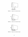
Display Unit Installation Step 1 ••••••••••••••••••••••••••
Display Unit Installation Step 2 ••••••••••••••••••••••••••
Display Unit Installation Step 3 ••••••••••••••••••••••••••
Display Unit Positioning ••••••••••••••••••••••••••••••••••
VME/10 with I/Oloodule Expansion Card Cage •••••••••••••••••
I/Omodule Expansion Card Cage •••••••••••••••••••••••••••••
MVME400 Port 1 Modern Configuration ••••••••••••••••••••••••
MVME410 Port 1 Printer Configuration ••••••••••••••••••••••
VME/10 with VME+I/Omodule Expansion Card Cage •••••••••••••
VME+I/Qnodule Expansion Card Cage •••••••••••••••••••••••••
MVME923 Backplane Daisy-Chain •••••••••••••••••••••••••••••
Typical VMElnodule Bus Arbitration Bypass••••••••••••••••••
Typical VMEm:>dule Bus Arbitration Level Selection •••••••••
VMEmodule I/O Cabling Method 1 ••••••••••••••••••••••••••••
Present Production Control Unit Chassis I/O Panel Templet ••
First Production Control Unit Chassis I/O Panel Templet •••
VMEm:>dule I/O Cabling Method 2 ••••••••••••••••••••••••••••
1-2
2-1
2-2
2-3
2-5
2-5
2-6
2-7
2-7
2-7
2-8
3-2
3-3
3-6
3-9
4-2
4-3
4-4
4-6
4-7
4-10
4-13
4-14
4-16
LIST OF TABLES
TABLE 1-1.
3-1.
3-2.
VME/10 S~cifications •••••••••••••••••••••••••••••••••••••
MVME400 Port 1 Modern Configuration ••••••••••••••••••••••••
MVME410 Port 1 Printer Configuration ••••••••••••••••••••••
ii
1-3
3-5
3-8
OIAPTER 1
GENERAL INFORMATION
1.1
INTRODUcrION
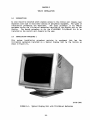
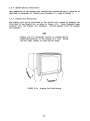
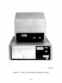
This installation guide provides general information, VME/10 installation,
I/Omodule expansion card cage, and VME+ I/Omodule expansion card cage equipment
installation information for the VME/10 Microcanputer System (hereafter referred
to as VME/10) as shown in Figure 1-1.
Included in this chapter are the
unpacking instructions, equipment supplied listing, arrl equipment specifications
necessary for the user to unpack and install the VME/10.
1.2
UNPACK!~
INSTRUCTIONS
NOTE
If shipping cartons are damaged upon receipt,
request carrier's agent be present during
unpacking arrl inspection of equipement.
Unpack equipnent from shipping cartons. Refer to packing list arrl verify that
all ite:ns are present. Save i;acking material for storing or reshipping the
equipment.
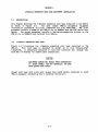
1.3 SYSTEM EQUIPMENT SUPPLIED
The VME/10 Microcanputer System soould be inspectErl for missing or damaged i terns
before attempting installation. !tans supplied are listed below:
•
•
•
•
•
•
•
•
•
•
Keyboard
Keyboard cable (6-wire cable)
Control unit chassis
Chassis ac power cord (3-wire cable)
Display unit (monochrome/color)
Monitor data cable (1)
Monitor de power cable (2)
Monitor data/de power cable (3)
Monitor ac power cord (4)
Tilt/swivel med:lanism
NOTES: (1) 14-wire ribbon cable (first production monochrane display units).
(2) 3-wire cable (first production monochrane display units).
(3) 16-wire shielded ribbon cable (used with monochrane/color display
units).
(4) 3-wire cable (used with color display unit).
1-1
6-83-1537
FIGURE 1-1.
Typical VME/10 Microcanputer System
1-2
TWo types of tilt/swivel mechanisms are utilized in the production of the
VME/10. One type is mounted on the display unit; the other type (first
production units) is provided in a kit form which is mounted on the control unit
chassis by the user.
1.4
SPE:IFICATI~
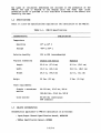
Table 1-1 lists the specifications required for the installation of the VME/10.
TABLE 1-1.
VME/10 Specifications
CHARAcrERI STIC
SPOCIFICATION
Temperab.lre
c
Operating
10° to 40°
Storage
-400 to 60° c
Relative humidity
10% to 80% (noncondensing)
Physical dimensions
Chassis and monitor
Keyboard
Ieng th
22.8 in. (57.9 an)
8.3 in. (21.1 cm)
Width
19.0 in. (48.3
19.0 in. (48.3
Height
20.0 in. (50.8 an)
2.0 in. (5.1 an)
50 lbs. (23 kg)
5 lbs. (2.3 kg)
Weight
an)
Power requirements
Chassis + monochrane
iooni tor
90-132 Vac, 47-63 Hz, 500 W
180-264 Vac, 47-63 Hz, 500 W
Color monitor
85-270 Vac (continuous)
60W (naninal)
1.5 RELATED D<X!U.MENTATION
Documentation applicable to VME/10 installation is as follows:
• Input/Output Channel Specification Manual, M68RIOCS
• VMEbus Specification Manual, MVMEBS
1-3/1-4
cm)
OIAPTER 2
VME/10 INSTALLATION
2.1
INTRODUCI'ION
An area should be selectErl which enables access to the control unit chassis rear
expansion card cage to facilitate cabling of peripheral equipment. Two types of
installation procErlures are described.
The first procedure is for VME/10
equiJ;XI\ent having the tilt/swivel mechanism installed on the display unit by the
factory.
The secorrl procedure is for the 67-W2420B01 Tilt/Swivel Kit to be
installed on the control unit chassis by the user.
2.2
INSTALLATION PROCEDURE 1
This systan installation procedure pertains to equipment that has the
tilt/swivel mechanism installa:l on a typical display unit by the factory as
shown in Figure 2-1.
10-83-1800
FIGURE 2-1.
Typical Display Unit with Tilt/Swivel Mechanism
2-1
Perform the installation procedure as follows:
a.
Place control unit chassis in desirerl location.
b.
If display unit tilt/swivel mechanism requires tension adjustment,
remove four screws that secure tilt/swivel mechanism to display unit.
Tension crljustment is accanplished as illustrated in Figure 2-2.
FIGURE 2-2.
Display Unit Tilt/Swivel Adjustment
c.
Place display unit on top of control unit chassis.
d.
Connect one errl of the applicable monitor data cable to the display unit
connector Jl. Connect the other errl of the cable to the control unit
chassis connector J3.
NOTE
Sane monitor data cables utilize a keyerl latching connectors.
Other data cable connectors require the use of two phillips
M3.5 x 0.6 x 10 screws to secure the cable to the display
unit/control unit chassis.
e.
Connect monitor ,POwer cable/cord to the display unit.
NOTE
Some nnnochrome nnnitors utilize a de power cable.
connect one errl of the monitor de ,POwer cable to the display unit
connector labeled 24 Vdc. Connect the other eoo of the cable to the
control unit chassis·connector labeled 24 Vdc.
NOTE
Some monochrane monitors utilize a data/de power cable
with keyai latching connectors.
This de power connection is automatically implemented by step d.
2-2
f.
Connect one errl of the keyboard cable to the keyboard rear mounted
modular RJ type connector. Connect the other end of the cable to either
modular RJ type connector located on the control unit chassis front
panel.
g.
Connect ac power cord into the control unit chassis power receptacle.
NOTE
Color nx>nitors utilize a 115/220 Vac power cord.
Connect ac power cord into the color display unit power receptacle.
2.3
h.
With the control unit chassis/color display unit power switch placed in
the off position (0), connect the ac power cord to the ac power source.
i.
Refer to the VME/10 Microcanputer System Overview Manual, Motorola
publication number M68KVSOM, for VME/10 systan power-up and operating
instructions.
INSTALLATION PROCEDURE 2
The following installation instructions provide the user with the necessary
information to install the 67-W2420B01 Tilt/Swivel Kit on a control unit chassis
as stx>wn in Figure 2-3. This tilt/swivel kit is designed to mount the display
unit to the control unit chassis.
10-83-1799
FIGURE 2-3.
Control Unit Chassis with Tilt/swivel Asseni>ly
2-3
2.3.1
Fquipnent Supplied
The tilt/swivel kit should be inspected for missing or damaged parts before
attempting installation. Parts supplied are listed below.
2.3.2
ITEM
NUMBER
PART
NUMBER
1
07-W4472B01
Assenbly, tilt/swivel
1
2
03SW994D904
Screw, ph il 1 ips,
MS x o.8 x 10
4
3
035W993D910
Screw, phillips,
M3.S x 0.6 x 10
4
DESCRIPTION
QUANTITY
Tilt/Swivel Assembly Installation
The user should read the following procedure canpletely before starting the
installation.
a.
Place control unit chassis in desired location.
b.
Position tilt/swivel assembly on control unit chassis as shown in
Figure 2-4.
c.
Install two, iten number 2, phillips MS x 0.8 x 10 screws as shown in
Figure 2-4.
d.
Position tilt/swivel assembly on control unit chassis as shown in
Figure 2-S.
e.
Install the ranaining two, iten number 2, phillips MS x 0.8 x 10
screws as shown in Figure 2-S.
f.
Lubricate tilt/swivel brackets as shown in Figure 2-6. An al 1 purpose
lubricant, such as Lubriplate number 23-2S or equivalent, is
recomnended.
g.
Proceed to the display unit installation instructions.
2-4
-------ffi
I
I
I
I
I
I
I
I
I
I
I
I
I
I
I
t,;. _______ .
FRONT
FIGURE 2-4.
Control Unit Chassis Tilt/Swivel Asserrbly Position 1
FIGURE 2-5.
Control Unit Chassis Tilt/Swivel Asserrbly Position 2
2-5
LUBRICANT
LUBtltCANT
-----------~~----------
FIGURE 2-6.
Control Unit Chassis Tilt/Swivel Assembly Lubrication
2.3.3 Display Unit Installation
Upon completion of the tilt/swivel assembly installation, the display unit is
mounten to the control unit chassis (via the tilt/swivel assembly) as follows:
NOTE
Underside of display unit contains two
channels where tilt/swivel brackets are
inserta::I.
a.
Loosen display unit cover screws (two per side) closest to front monitor
bezel. This enables easy insertion of the tilt/swivel bracket into the
display unit.
b.
Position display unit over tilt/swivel bracket as shown in Figure 2-7.
Align screw position over bracket channel as depected in illustration.
c.
Insert display unit onto tilt/swivel brackets and slide display unit
forward as soown in Figure 2-8.
NOTE
While slidirg display unit forward,
display unit will drop into the
forward tilt/swivel bracket channels.
d.
Push display unit down as shown in Figure 2-9.
properly insertE:rl into the tilt/swivel assembly.
e.
Tighten display unit cover screws (two per side) closest to front
monitor bezel to obtain the desired display uni't tilt adjustment
tension.
2-6
Display unit is now
"
•
•
FIGURE 2-7.
•
Display Unit Installation Step 1
..
FIGURE 2-8.
Display Unit Installation Step
FIGURE 2-9.
Display Unit Installation Step 3
2-7
~
2.3.4
System Cablirg Installation
Upon canpletion of the display unit installation, system cabling is installed as
described in paragraph 2.2 (Installation Procerlure 1), steps d through i.
2.3.5 Display Unit Positioning
The display unit can be positionerl on the control unit chassis by grasping the
front part of the display unit as shown in Figure 2-10. Slight downward thumb
pressure tilts the display unit downward. Lifting uµ.1ards tilts the display
unit upwards.
NOTE
Display unit tilt adjustment tension is accanplished by
loosening/tightening of the display unit cover screws
(two per side) closest to front monitor bezel.
FIGURE 2-10.
Display Unit Positioning
2-8
OIAPI'ER 3
I/Qnodule EXPANSION CARD CAGE EC.UIPMENT INSTALLATION
3.1
INTRODUCTION
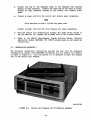
This chapter describes the I/Qnodule expansion card cage installed in the VME/10
as shown in Figure 3-1.
Two most camnon VME/10 peripheral equipnent
installation procErlures utilizing I/Qnodules are also described.
The first
procerlure installs a modem to the VME/10 via an MVME400 Dual RS-232C Serial Port
Module. The secorxl procedure installs a Centronics-canpatible printer to the
VME/10 via an MVME410 Dual Parallel Port Module.
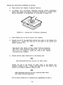
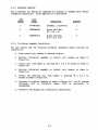
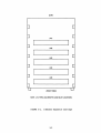
3. 2 I/Qnodule EXPANSION CARD CAGE
Figure 3-2 illustrates the I/Qnodule expansion card cage installed in the
VME/10.
'!his card cage is designerl to accept up to five "single-wide"
I/Qnodules. Jl connectors installerl at card slot locations (Al) through (AS)
form the I/O Channel via ribbon cable connections.
CAUTION
EQUIPMENT DAMAGE MAY RESULT FROM OVERHEATING
IF BLANK PANELS ARE NOT INSTALLED ON CARD
CAGE UNUSED CARD SLOTS.
Unused card cage card slots must always have blank panels installed to avoid
VME/10 equipnent overheating due to escaping cooling air.
3-1
6-83-1538
FIGURE 3-1.
VME/10 with I/Qnodule Expansion Card Cage
3-2
(TOP)
(A1)
(A2)
(A3)
(A4)
(AS)
(FRONT VIEW)
NOTE: (A 1) THRU (AS) DENOTE CARD SLOT LOCATIONS.
FIGURE 3-2.
I/Qnodule Expansion Card Cage
3-3
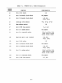
3.3
VME/10 TO MODEM INSTALLATION
To connect the VME/10 to a modem, the MVME400 Dual RS-232C Serial Port Module
jumper headers are prepared as listed in Table 3-1 and as shown in Figure 3-3.
For specific details about the jumper header configurations, refer to the
MVME400 Dual RS-232C Serial Port Module User's Manual, Motorola publication
number MVME400.
NOTE
The MVME400 Dual RS-232C Serial Port Module is supported
by the VME/10 VERSAdos SYOOEN comnand file.
The MVME400 is configured to operate in the VME/10 I/O Channel at interrupt
level 4. This is established by the VME/10 VERSAdos SYOOEN file specifically
for
the MVME400.
Baud rate operation is hardware-configured and
software-selected.
To install the MVME400 into the I/Omodule expansion card cage, proceed as
follows:
a.
Turn off equipment power.
CAUTION
CONNECTING MODULES WHILE POWER IS ON COULD RESULT
IN DAMAGE TO CDMPONENTS ON THE MODULE.
b.
Refer to Table 3-1 and Figure 3-3 and configure the MVME400 jumper
headers for port 1 modem operation, interrupt level 4, and baud rate
9,600.
c.
Remove two blank panels and insert MVME400 in desired card slot.
d.
Secure MVME400 in place with two captive screws.
e.
Connect modem device via Motorola part number M68RS232-10, -25, -50
RS-232C type cable to the MVME400 front panel connector labeled PORT 1.
f.
Turn on equipment power.
g.
Refer to the Systan Generation Facility User's Manual, Motorola
publication number M68KSYSGEN, for details on setting the paraneters in
the VME/10 VERSAdos SYOOEN comnand file (VMESlO.SYSCMD.SA) to reflect
the desired MVME400 configuration.
3-4
TABLE 3-1.
HEADER
NUMBER
MVME400 Port 1 Modem Configuration
FUNCTION
CONFIGURATION
J2
Port 2 TxC select
J3
Port 2 external clock select
J4
Port 2 internal clock select
JS
Interrupt level select
J6
Base address select
J7
Port 2 crs flow control
J8
Port 2 to modan select
No jumpers
J9
Port 2 to tenninal select
1-2, 3-4, 5-6, 7-8,
9-10, 11-12, 13-14,
15-16, 17-18, 19-20
JlO
Baud rate port 1 and 2 select
Jll
Port 1 TxC select
Jl2
Port 1 external clock select
Jl3
Port 1 internal clock select
Jl4
Port 1 to modem select
1-2, 3-4, 5-6, 7-8,
9-10, 11-12, 13-14,
15-16, 17-18, 19-20
Jl5
Port 1 to tenninal select
No jumpers
Jl6
Port 1 crs flow control
1-2
No
jumpers
1-2, 3-4
9-10, 11-12
4-6, 10-12, 16-18
7-8
5-7, 6-8
3-4, 5-6,
9-10, 11-12
1-2
No jumpers
1-2, 3-4
9-10, 11-12
5-7, 6-8
3-5
FAIL
0
20
JS
PORT
PORT
1
2
J&
.........
... 2
2
00
00
00
1900
J 10
12
l~u~nl
: : J9
11
...
...
...
. . . 20
00
00
00
0 0
00
00
0 0
____0
0
J15
2
8
fOO"Hl J16
o_o_~
@-..
~~~~~~~
1920 1920
1
1
MVME400
FIGURE 3-3.
MVME400 Port 1 Modem Configuration
2
8
1
1
19
Loo
o•1
oooe
3.4 VME/10 TO PRINTER INSTALLATION
To connect the VME/10 to a Centronics-compatible
Parallel Port Module jmnper headers are prepared as
shown in Figure 3-4.
For specific details
configurations, refer to the MVME410 Dual Parallel
Motorola publication number MVME410.
printer, the MVME410 Dual
listed in Table 3-2 and as
about the jumper header
Port Module User's Manual,
NOTE
The MVME410 Dual Parallel Port Module is supported
by the VME/10 VERS.Ados SYSGEN co:rrmand file.
The MVME410 is configured to operate in the VME/10 I/0 Channel at interrupt
level 1. This is established by the VME/10 VERSAdos SYSGEN file specifically
for the MVME410.
To install the MVME410 into the I/Qnodule expansion card cage, proceed as
follows:
a.
Turn off equipment power.
CAUTION
CONNECTING MODULES WHILE POWER IS ON COULD RESULT
IN DAMAGE TO COMPONENTS ON THE MODULE.
b.
Refer to Table 3-2 and Figure 3-4 and configure the MVME410 I/Qnodule
jumper headers for port 1 printer operation and interrupt level 1.
c.
Remove one blank panel arrl insert MVME410 in desired card slot.
a.
Secure MVME410 in place with two captive screws.
e.
Connect printer device via Motorola part number M68KVMPRTCE type cable
to the MVME410 front panel connector Jl.
f.
Turn on equipment power.
g.
Refer to the System Generation Facility User's Manual, Motorola
publication number M68KSYSGEN, for details on setting the parameters in
the VME/10 VERS.Ados SYSGEN cornnand file (VMESlO .SYSCMD.SA) to reflect
the desired MVME410 configuration.
3-7
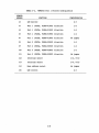
TABLE 3-2.
MVME410 Port 1 Printer Configuration
HEADER
NUMBER
FUNCTION
CONFIGURATION
J2
LED monitor
2-3
J3
Port 1 (PlCA2, PlPA0-PlPA7) direction
1-2
J4
Port 1 (PlCA2, PlPAO-PlPA7) direction
1~2
JS
Port 1 (PlCB2, PlPBO-PlPB7) direction
1-2
J6
Port 1 (PlCB2, P2PBO-PlPB7) direction
No jurrper
J8
Port 2 (P2CA2, P2PA0-P2PA7) direction
1-2
J9
Port 2 (P2CA2, P2PAO-P2PA7) direction
1-2
JlO
Port 2 (P2CB2, P2PBO-P2PB7) direction
1-2
Jll
Port 2 (P2CB2, P2PBO-P2PB7) direction
No jurrper
Jl2
Interrupt select
2-4, 8-10
Jl3
Interrupt select
2-4, 8-10
Jl4
Base address select
No junper
Jl5
LED control
2-3
3-8
@
FAILQ
J3
JS
1C!:!)2
~~
J2
1ra
J9
1(.... ool4
1(.... 0 of4
182
JS
:11~4
J6
~;.-
J1
~
/
s.
1(EJ2
J4
182
12
12
.. o .. o
000000
1 J12 11
... 0 ... 0
000000
1
J10
1(000014
J11
2
•
(0'0001
~
~ J16
1
1(0 . . . ol4
..............
J15
@-..
MVME410
@
FIGURE 3-4.
MVME410 Port 1 Printer Configuration
J14
7
J13
11
CliAPI'ER
4
VME+I/Qnodule EXPANSION CARD CAGE EQUIPMENT INSTALLATION
4.1
INTRODUCI1ION
This chapter describes the VME+I/Qnodule expansion card cage installed in the
VME/10 as shown in Figure 4-1. VMEhtodule and I/Qnodule installation procerlures
are also provided.
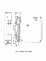
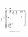
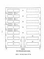
4.2 VME+I/Qnodule EXPANSION CARD CAGE
Figure 4-2 illustrates the VME+I/Qnodule expansion card cage installed in the
VME/10. This card cage facilitates the installation of up to five "double-wide"
VMEhlodules and up to four "single-wide" I/Onodules. The card cage houses the
MVME923 Backplane which contains five connectors (Jl through JS) that mate to
VMEhtodule Pl connectors, and two connectors (Jl4 and JlS) that mate to I/Qnodule
Pl connectors. Connectors Jl through JS form the VMEbus, and connectors Jl4 and
JlS form the I/O Channel. The I/O Channel is extended from the backplane by the
addition of two connectors (card slot locations AS and A9) via ribbon cable
connection.
The card cage also provides a connector mounting area. See Figure 4-2. Up to
five connectors can be installed by the user to facilitate VME1nodule P2 I/O
cabling.
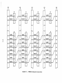
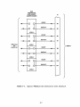
4.2.1 Daisy-Chain Jumpering (J6-Jl3)
Vacant card slots should not exist between inserterl VMEmodules requiring
Interrupt Acknowlerlge (!ACK) and Bus Grant (BG) signals in the card cage unless
the vacant slots have been daisy-chain jumpererl on the MVME923 backplane.
Daisy-chain jumpering penni ts the !ACK and BG signals to propagate from card
slot (Al) to the last card slot (AS). Remaining vacant slots following the last
active ca.rd slot (Ax) are not required to be daisy-chain jumpered.
Jumper
headers J6 through Jl3 on the backplane facilitate the daisy-chain jumpering
technique.
Figure 4-2 illustrates the backplane daisy-chain jumper header
locations. Card slot (Al) is not assignerl a jumper header. Headers J6 and JlO
are assigned to slot (A2), headers J7 and Jll to slot (A3), headers JS and Jl2
to slot (A4) , and headers J9 and Jl3 to slot (AS) • Backplane jumper header pin
and signal assignments are illustrated in Figure 4-3.
4-1
10-83-1797
FIGURE 4-1.
VME/10 with VME+I/Qnodule Expansion Card Cage
4-2
(A1)
J1
J6
1
L----------------~
I ....... · I a
1c::J2 J10
(A2)
J2
J7
1
1
1c::J2 J11
(A3)
t
w
1
r---------------1I
I
L---------------~
I· ...... · I a
1 8 2 J12
(A4)
J4
J9
r---------------1I
I
L---------------~
I ........ I a
J3
JS
r----------------1I
I
r----------------1I
I
L---------------~
I · · · · · · .. I a
1 8 2 J13
JS
(AS)
r---------------1I
I
L---------------~
(AS)
(A6)
J14
(A7)
(A9)
J1S
(FRONT VIEW)
NOTE: (A1) THAU (A9) DENOTE CARD SLOT LOCATIONS.
FIGURE 4-2.
VME+I/Qnodule Expansion Card Cage
(A1)
J1
(A2)
J2
(A3)
J3
J10
A21
J11
IACKIN*
A21
IACK OUT*
IACKOUT*
8GOIN*
8GOIN*
8GOOUT*
~
I
8G20UT*
8G31N*
811
8G20UT*
8G31N*
89
8G31N*
810
8G30UT*
811
FIGURE 4-3.
88
89
810
8G30UT*
8G30UT*
811
8G21N*
8G20UT*
8G31N*
87
88
89
810
810
86
8G10UT*
8G21N*
8G20UT*
8S
87
88
89
8GOOUT*
8G11N*
8G10UT*
8G21N*
MVME923 Backplane Daisy-Chain
1
84
86
87
88
89
8G11N*
8G10UT*
8G21N*
88
8S
86
87
8GOIN*
84
8GOOUT*
8G11N*
8G10UT*
A22
J9
8GOIN*
8S
86
87
IACKOUT*
A22
84
8GOOUT*
8G11N*
86
A21
JS
1
8S
8S
~
IACK OUT*
84
84
IACKIN*
A21
J7
J6
J13
IACKIN*
A22
A22
(AS)
JS
J12
IACKIN*
A21
A22
(A4)
J4
810
8G30UT*
811
811
4.2.1.1 VMEmodules Not Containing IACK/BG Circuitry. If a VMEmodule which does
not contain !ACK/BG circuitry (e.g., MVME200 64K-Byte Dynamic Memory Module) is
inserted into the card cage, one of two operations must be perforrred:
a. the applicable card slot
daisy-chain jumpered, or
jurcper headers
on
the backplane must be
b. the applicable VMEmodule must be jumpered for IACK/BG signal bypass
operation.
VMEhlodule edge connector IACK/BG signal bypass method is illustrated in Figure
4-4. This bypass method ensures that the IACK/BG signals will propagate to the
next card slot, without the use of the backplane jurcper headers.
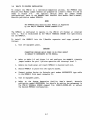
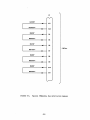
4.2.1.2 VMEmodules Containing IACK/BG Circuitry. If a VMErnodule which contains
IACK/BG circuitry (e.g. , MVME300 GPIB Controller) is inserted into the card
cage, the BG circuitry must have jumpers installed to receive the selected BG
signal and to transfer the unused BG signals to the next card slot. For this
application, the applicable card slot jumper headers on the backplane should not
have jurcpers installed. Installed jurcpers will bypass all IACK/BG signals to
the next card slot, thus defeating the purpose of the module IACK/BG circuitry.
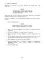
Figure 4-5 illustrates a typical VMEmodule bus arbitration level select jumper
header.
In this figure, BG2* signals are the only signals permitted to be
received/transferred by the VMF.rnodule BG circuitry by the placement of the
horizontal jumpers. Unused BGO*, BGl*, arrl BG3* signals are bypassed to the
next card slot by the placement of the vertical jumpers.
4-5
P1
~
IACKIN*
I ACK OUT*
BGOIN*
BGOOUT*
BG11N*
---.--
A21
A22
-.--
84
es
--
~
86
VMEbus
BG10UT*
-
87
-..
BG21N*
--
~
BG20UT*
--
89
-..
BG31N*
BG30UT*
88
----
----
810
811
~
FIGURE 4-4.
Typical VMFroodule Bus Arbitration Bypass
4-6
BUS
ARBITRATION
LEVEL SELECT
JUMPER HEADER
P1
BGOIN*
B4
BGOOUT*
BS
LEVEL 0
BG11N*
B6
BG10UT*
VMEmodule
BG
CIRCUITRY
B7
LEVEL 1
VMEbus
BG21N*
BS
BG20UT*
B9
LEVEL 2
BG31N*
B10
BG30UT*·
B11
LEVEL 3
FIGURE 4-5.
Typical VMFJ:nodule Bus Arbitration Level Selection
4-7
4.3
VMElnodule INSTALLATION
VMF.rnodules are
Figure 4-2.
installed in card slot locations
(Al)
through
(AS).
See
CAUTION
EQUIPMENT DAMAGE MAY RESULT FROM OVERHEATING
IF BLANK PANELS ARE NOT INSTALLED ON CARD
CAGE UNUSED CARD SLOTS.
Unused card cage slots must always have blank panels installed to avoid VME/10
equipment overheating due to escaping cooling air.
To install a VMF.rnodule into the VME+I/Qnodule expansion card cage, proceed as
follows:
a. Turn off equipment power.
CAUTION
CONNECrING MODULES WHILE POWER IS ON COULD
RESULT IN DAMAGE TO CX>MPONENTS ON THE MODULE.
b. Refer to the applicable VMEmodule user's manual for hardware preparation
procedures.
c. Configure the VMEmodule (via jumper headers) as required.
d. Remove blank panel and insert VMErnodule in desired "double-wide" card
slot.
e. If the VMEmodule requires P2 I/O cabling, perform one of the two I/O
cabling installation methods described in paragraph 4.3.l or 4.3.2.
f. Secure VMErnodule in place with two captive screws.
g. Connect peripheral device (if required) to VMF.module as described in
applicable
VMElnodule
user's
manual
(Chapter
2,
INSTALLATION
INSTRUCTIONS).
h. Turn on equipment power.
4-8
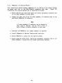
4.3.1 VMEh\odule I/O Cabling Method 1
This installation method enables VMEmodule P2 I/O cabling to be routed through
an unused card slot in the VME+ I/Omodule expansion card cage.
Figure 4-6
illustrates this cabling method and is installed as follows:
a. Remove desired card cage blank panel and install peripheral connector end
of I/O cable assembly to blank panel.
b. Connect the other end of the I/O cable assembly (J2 connector end) to the
applicable VMEmodule P2 connector.
NOTE
I/O cable assembly J2 connector can be mounted to
card cage if desired. Use two M2.5 x 0.45 x 8
metric screws to secure connector to card cage.
c. Configure the
VM~odule
(via jurrper headers) as required.
d. Install VMEmodule in desired "double-wide" card slot.
e. Secure VMFroodule in place with two captive screws.
f. Secure modified blank panel (containing peripheral connector end of I/O
cable assembly) in place with two screws (previously removed).
4-9
FIGURE 4_6 • VMEmodule I/O Cabllng
.
Method 1
4-10
4.3.2 VMF.lnodule I/O Cabling Method 2
This installation metood enables VMEmodule P2 I/O cabling to be routed fran the
rear of the VME+I/Om:>dule expansion card cage, under the blower fan, to the rear
I/O panel.
This cabling method is accanplished by the control unit chassis
disassembly, I/O cable asserri::>ly installation, arrl control unit chassis
reassembly.
The control unit chassis is disassembled as follows:
a. Disconnect system ac power.
WARNING
AC J?Cl'lER MUST BE REMOVED TO AVOID
ELECl'RICAL SHOCKS TO MAINTENANCE PERSONNEL.
b. Remove all external cables from control unit chassis.
c. Remove display unit from control unit chassis.
d. Remove control unit chassis side covers.
two pan~head screws per side).
(Accanplished by the removal of
e. Remove control unit chassis top cover.
seven pan-head screws).
(Accanplished by the removal of
f. Remove control unit chassis front panel.
two flat-head screws per side.)
(Accanplished by the removal of
CAUTION
'!WO MODULAR RJ TYPE CDNNEcrORS SHOOLD BE REMOVED FROM
FRONT PANEL OR CDNNEX::TOR WIRING SHOOLD BE DISCDNNOCTID
FROM CABLE HARNESS TO AVOID CDNNEcrOR WIRING DAMAGE.
g. On present production units, disconnect front panel modular RJ type
connector wiring from cable harness.
(Accanplished by cable harness
quick disconnect connectors.)
h. On first production units, ranove connector bracket arrl both modular RJ
type connectors from front panel.
(Accanplished by the removal of two
pan-head screws.)
4-11
The Systan Control Module (SCM) is now removed fran the control unit chassis to
gain access for the I/O cable assembly installation. The SCM is removed as
follows:
a. Disconnect cable assembly connectors
locations: Jl, P2, Jl2, Jl3, and Jl4.
at
following
SCM
connector
NOTE
Observe orientation of connectors Jl2 arrl Pl2.
Pl2 red wire must mate with Jl2 pin 1.
b. Remove Sa1 (including bracket assembly) fran chassis.
the removal of three flat-head screws per side.)
(Accanplished by
c. SCM (with bracket assembly) is removed from the chassis by pulling
forward on the SCM.
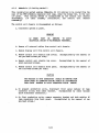
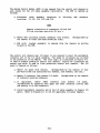
The control unit chassis rear I/O panel is now removed to mount the peripheral
connector en:3 of the I/O cable assembly. Two types of I/O panels are utilized
in the production of the VME/10. The first type, as illustrated in Figure 4-7,
is used on present production control unit chassis. Figure 4-8 illustrates the
second type whidl is usErl on first production control unit chassis. The I/O
panel is removed as follows:
a. Remove I/O panel fran chassis.
(Accanplished by the removal of four
pan-head screws and associated flat washers, lock washers, arrl nuts.)
b. Remove J3 connector from chassis I/O panel.
of connector mounting hardware.)
(Accanplished by the removal
c. If applicable, remove 24VDC connector fr an chassis I/O panel.
(Accanplished by squeezing both upper and lower connector locking tabs
an:3 pushing in on the connector.)
d. Install peripheral connector errl of the I/O cable assembly to chassis I/O
pmel. Refer to Figures 4- 7 or 4-8 for applicable I/O panel tanplet.
4-12
(P2)
1/0 CONNECTOR
--MOUNTING
AREA
0
r---------
0
J3
0
L ____________
0
FIGURE 4-7.
_J
0
Present Production Control Unit Chassis I/O Panel Tanplet
4-13
( 112)
1/0 CONNECTOR
MOUNTING
AREA
0
r---------
0
J3
24VDC
0
L ____________ _..
0
FIGURE 4-8.
0
First Production Control Unit Chassis I/O Panel Templet
4-14
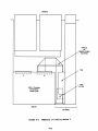
The I/O cable assembly is now installed into the control unit chassis.
as follows:
Proceed
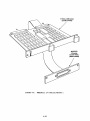
a. Route I/O cable assenbly as shown in Figure 4-9.
CAUTION
BLOCKAGE CF BLCMER FAN COOL!~ COULD RESULT
IN EQUIPMENT DAMAGE DUE TO OVERHEAT!~.
b. I/O cable assembly must be routed under the blower fan arrl over the EMI
filter.
c. Connect the J2 connector errl of the I/O cable assembly to the
VME+I/Qnodule expansion card cage using two M2.5 x 0.45 x 8 metric
screws.
d. Reinstall J3 connector to chassis I/O panel.
e. If applicable, reinstall 24VDC connector to chassis I/O panel.
f. Reinstall I/O panel to control unit chassis.
not blocking air flow fran blower fan.
Ensure that I/O cabling is
The control unit chassis is reassembled as follows:
a. Reinstall SCM (with bracket asserrbly)
mates with card cage connector XJl.)
b. Reinstall
SCM
to chassis.
(SCM
Pl connector
Jl, P2, Jl2, Jl3, arrl Jl4 cabling.
NOTE
Observe orientation of connectors Jl2 and Pl2.
Pl2 red wire must mate with Jl2 pin 1.
c. Reconnect modular RJ type connector wiring to cable harness or reinstall
modular RJ type connectors to front panel.
d. Reinstall front panel to chassis.
e. Reinstall top cover to chassis.
f. Reinstall chassis side covers.
VME1nodule, utilizing the I/O cable assembly just installed, can now be prepared
and installed. Refer to paragraph 4.3.
4-15
(FRONT)
TYPICAL
P2
RIBBON CABLE
ROUTING
FAN
I
I
I
I
L-------...1
'--------...I
J1
J2
EMI
FILTER
VME + l/Omodule
EXPANSION
CARD CAGE
r
I
I
I
I
I.._
__
v
'-----------"'
(REAR)
1/0 PANEL
FIGURE 4-9.
VMDnodule I/O Cabli~ Method 2
4-16
4.4
I/Qnodule INSTALIATION
I/Qnodules are
Figure 4-2.
installed in card slot locations
(A6)
through
(A9}.
See
NOTE
Both I/Oloc>dule installation procErlures described in
Chapter 3 are also applicable to the VME+I/Qnodule
expansion card cage.
When inserting "double-wide" front panel I/Qnodules (e.g., MVME400 dual RS-232C
Serial Port Module) into this card cage, considerations about sacrificing card
slots for sp:!cific I/Qnodule installations must be made. For an example, if two
MVME400 are requirErl, the user has two options available •
• Install both I/Qnodules in card slots (A7) and (A9), therefore sacrificing
card slots (A6) am (AS) •
• Install both I/Omodules in card slots (A6) am (AS), therefore sacrificing
card slot (AS) which is a "double-wide" VMEmodule card slot.
CAUTION
EQUIPMENT DAMAGE MAY RESULT FROM OVERHEAT!~ IF
BLANK PANELS ARE NOT INSTALLED ON CARD CAGE
UNUSED CARD SLOTS.
Unused card cage card slots must always have blank panels installed to avoid
VME/10 equi!lllent overheating due to escaping cooling air.
To install a I/Omodule into the VME+I/Omodule card cage proceed as follows:
a. Turn off equipment power.
CAUTION
<DNNECI'ING MODULES WHILE POWER IS ON COULD
RESULT IN DAMAGE TO <DMPONENTS ON THE MODULE.
b. Refer to the applicable I/Omodule user's manual for hardware preparation
procedures.
c. Configure the I/Oroodule (via
j~r
headers) as requirErl.
d. Remove blank panel arrl insert I/Qnodule in desired "single-wide" card
slot.
e. Secure I/Omodule in place with two captive screws.
f. Connect peripheral device to I/Omodule as described in applicable
I/Omodule user's manual (Chapter 2, INSTALIATION INSTRUCI'IONS).
g. Turn on equipment power.
4-17/4-lS
SUGGESTION/PROBLEM
REPORT
QUALITY
•
PEOPLE
•
PERFORMANCE
Motorola welcomes your comments on its products and publications. Please use this form.
To:
Motorola Inc.
Microsystems
2900 S. Diablo Way
Tempe, Arizona 85282
Attention: Publications Manager
Mai Id rop DW164
Product: _ _ _ _ _ _ _ _ _ _ _ _ _ __
Manual:---------------
Please Print
Name _ _ _ _ _ _ _ _ _ _ _ _ _ _ _
~
Company _ _ _ _ _ _ _ _ _ _ _ _ __
Title---------------Division---------------
Street----------------
Mail Drop _ _ _ _ _ Phone _ _ _ _ _ __
City _ _ _ _ _ _ _ _ _ _ _ _ _ _ _ __
State _ _ _ _ _ _ _ _ _ Zip _ _ _ __
For Additional Motorola Publications
Literature Distribution Center
616 West 24th Street
Tempe, AZ 85282
(602) 994-6561
Four Phase/Motorola Customer Support, Tempe Operations
(800) 528-1908
(602) 438-3100
®MOTOROLA
lil\
0
ltllOTOROLA Semiconductor Products Inc.
P.O. BOX 20912 •PHOENIX, ARIZONA 85036 •A SUBSIDIARY OF MOTOROLA INC.
17602 PRINTED IN USA (4/84) MPS
4M