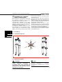
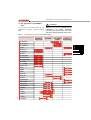
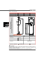
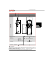
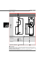
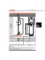
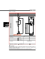
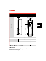
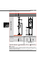
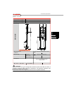
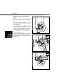
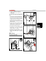
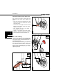
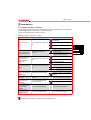
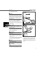
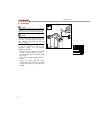
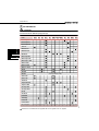
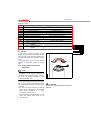
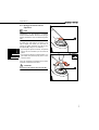
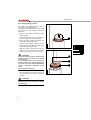
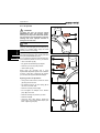
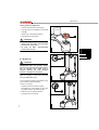
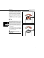
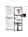
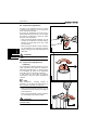
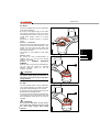
1
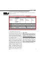
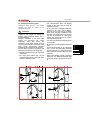
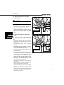
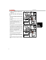
MODEL YEAR 2004
General warnings for owners manual
WARNING
Failure to follow these instructions could
result in failure of the product, an accident,
personal injury or death.
1. USE OF THE MANUAL
• Carefully read, follow and understand the
instructions given in this manual. It is an
essential part of the product, and you should
keep it in a safe place for future reference.
• If the use and maintenance instructions
provided in this manual are not properly
performed, or if the other instructions in this
manual are not followed, an accident could
occur, resulting in an accident, serious injury
or death.
• Please be advised that suspension system
installation and repair requires specialized
knowledge, tools and experience. General
mechanical aptitude may not be sufficient to
properly install or repair your suspension
system.
Please have your suspension
system installed and/or serviced only by an
authorized Marzocchi Service Center.
• Never make any modification whatsoever to
any component of your suspension system.
A. GENERAL SAFETY RECOMMENDATIONS
• Be sure to use the correct suspension system
for your style of riding. Check the “Intended
Use Instructions” in this manual.
• Please note that there are inherent risks
associated with downhill, free ride, cross
country, marathon, trekking, dirt jumping and
urban style riding. You could be seriously
injured or killed while engaged in those riding
styles. Learn how to ride, never ride beyond
your capabilities, be sure to use the proper
safety equipment, and be sure that all your
riding equipment is in excellent condition.
• The lifespan of Marzocchi products depends
on many factors, such as riding style and
riding conditions. Impacts, falls, improper use
or harsh use in general may compromise the
structural integrity of the suspension system
and significantly reduce its lifespan. Please
have your bicycle regularly inspected by a
qualified mechanic for any oil leaks, cracks,
deformation, or other signs of fatigue. The
frequency of inspection depends on many
factors; check with your authorized Marzocchi
representative to select a schedule that is
best for you. If the inspection reveals any
deformation, cracks, impact marks, stress
marks or bent parts, no matter how slight,
immediately have a Certified Marzocchi
Repair Center inspect the forks before you
ride again.
• When installing or removing your bicycle from
a bicycle carrier (roof rack or rear hitch
mount), be sure that you fully loosen the quick
release fastener on the carrier. In addition, be
sure that your bicycle is lifted from or installed
on the carrier in a perfectly vertical direction.
If the quick release fastener is not fully
loosened, or if there is any bending action
while installing or removing your bicycle, you
will scratch, bend or otherwise damage your
suspension system.
• If you strike at any speed any overhead
object, such as a parking garage, bridge, tree
limb or other abutment, with your bicycle while
your bicycle is attached to a bicycle carrier,
you can damage your forks. Have your forks
inspected by an authorized Marzocchi Service
Center before you ride.
• Always wear a properly fitted and fastened
bicycle helmet that has been approved by
ANSI or SNELL, and any other safety
equipment necessary for your riding style.
B. BEFORE EVERY RIDE
• Check that none of the components to your
suspension system, or the remainder of your
bicycle, are bent, deformed, cracked or
otherwise damaged.
• Check to be sure that all quick release
fasteners, nuts and bolts are properly
adjusted. Bounce the bicycle on the ground
and listen and look for anything which may be
loose.
MZ009_1
8
• Be sure that your wheels are perfectly
centered. Spin the wheels to be sure that
they do not wobble up and down or from side
to side, and that they do not make contact
with the fork legs or brake pads while rotating.
• Learn and follow the local bicycle laws and
regulations, and obey all traffic signals, signs
and laws while you ride.
DO NOT RIDE YOUR BICYCLE IF IT DOES
NOT PASS THIS PRE-RIDE TEST. CORRECT
ANY CONDITION BEFORE YOU RIDE.
INTENDED USE INSTRUCTIONS
SELECT THE CORRECT FORK FOR
YOUR RIDING STYLE AND RIDE
PROPERLY
Marzocchi suspension forks are among the
most durable and technologically advanced
forks on the market today. However, no fork can
withstand misuse, abuse or improper use that,
over a short period of time, can cause your forks
to fail when you least expect it.
It is critical that you select and use the fork that
is appropriate for your riding style, and that you
use the fork properly.
1. Identify Your Riding Style:
MZ009_1
Trekking: Trekking is similar to XC riding but
not as aggressive as XC. It involves slower
riding and no riding over obstacles such as
rocks, roots, or depressions. You should only
attach generators and racks to the designated
mounting points provided on the forks. Never
make any modification to your fork to attach any
equipment.
Cross Country (XC)/Marathon: Riding along
hilly trails where some bumps and smaller
obstacles, such as rocks, roots, or depressions,
may be encountered. XC riding does not
include jumps or “drops” (riding off rocks, fallen
trees or ledges) from any height. XC forks must
only be used with tires specifically designed for
cross country riding, or disk, rim or linear pull
brakes.
Free Ride (FR): This riding style is for skilled
riders and involves aggressive slopes, large
obstacles, and moderate jumps. Free Ride
forks should be used only with disk brakes as
well as frames, wheels and other components
specifically designed for Free Riding. The disk
brakes must be attached to the designated
mounting points provided on the fork. Never
make any modification to your fork to attach any
equipment.
Dirt Jumper (DJ) / Urban Riding: This “BMX”
or “motocross” style riding is only for the most
skilled riders and involves jumping from one
mound of dirt to another. It also includes riding
over and around “urban obstacles” such as
man-made or other concrete structures. These
forks should be used only with disk brakes, as
well as frames, wheels and other components
specifically designed for this riding style. The
disk brakes must be attached to the designated
mounting points provided on the fork. Never
make any modification to your fork to attach any
equipment.
Down Hill (DH) / Extreme Free Ride: This
discipline is only for professional or highly skilled
riders. It includes for relatively high jumps or
“drops” and negotiating larger obstacles such as
boulders, fallen trees or holes. These forks
should be used only with disk brakes, as well as
frames, wheels and other components
specifically designed for this riding style. The
disk brakes must be attached to the designated
mounting points provided on the fork. Never
make any modification to your fork to attach any
equipment.
WARNING
Ride only in areas specifically designated for
your riding style.
9
2. Select the Correct Fork for Your Riding Style from the Table Below.
Please see your Marzocchi retailer, or contact Marzocchi directly, if you require assistance in
selecting the correct fork.
Tab 1:
2004 Fork Riding Categories and Intended USE
XC/Marathon
Free Riding
DJ/Urban Riding
Down Hill/Extreme
Free Riding
Marathon SL
Marathon S
Z-150 Free Ride
Z-150 FR SL
Z-150 Drop-Off
Z.1 FR SL
Z.1 FR
Z.1 Drop-Off I
Z.1 Drop-Off II
Z.1 Wedge
Dirt Jumper I
Dirt Jumper II
Dirt Jumper III
Monster T
Super Monster
MX Comp
MX Pro
Shiver SC
Shiver SC
Super T Pro
MZ Comp
MZ Race
Drop Off Comp
Street DJ
Junior T
EXR Comp
EXR Pro
EXR Supra
Drop-Off Triple
Trekking
TXC
TXC ECC
888 R
888 RR
888 RT
Shiver DC
3. Do Not Misuse or Abuse Your Forks
Do not misuse or abuse your forks. Learn how
to ride, and always ride within your abilities. An
out-of-control ride puts the equivalent of years of
hard use on your forks after only a few rides.
Learn how to properly flow around obstacles on
the trail. Hitting obstacles such as rocks, trees
or holes straight on puts forces on your fork it
was not designed to absorb.
Landing improperly after a jump or drop also
puts forces on your fork it was not designed to
absorb. You should only perform jumps or
drops when a transition or down ramp is
available to help your bicycle absorb the impact
forces generated during the landing, and both
wheels should smoothly make contact with the
transition or down ramp at the same time. Any
other type of landing is dangerous, as it could
result in a component part failure and an
accident. The steepness and length of the
transition or down ramp depends on the height
from which you jump or drop. Every situation is
different for every rider; consult with an
experienced rider before attempting any jump or
drop.
WARNING
Failure to properly flow around obstacles on
the trail, or failure to properly land after a
jump or drop could cause your forks to fail,
resulting in a loss of bicycle control and
serious injury or death to the rider.
Your forks require regular maintenance and
repair. The harder you ride, the more often you
must inspect and maintain your forks. If your
forks are bent, deformed, cracked, or
chipped, no matter how slight, immediately
have a Certified Marzocchi Repair Center
inspect the forks before you ride again.
MZ009_1
10
REMEMBER
Even forks made out of solid metal will fail if they are misused, abused, or improperly used!
Extreme use can eventually wear out and break even the strongest components.
MZ009_1
“Ride fast, yet ride Smart”
11
MZ009_1
English
Use and maintenance instruction manual
Contents
CONTENTS
1.1
1.1.2
Editorial pictograms .................... 98
2.1
English
I
Adjustments.................................... 128
Preload........................................... 129
5.1.1
Spring preload with external
adjustment ................................ 129
5.1.2
Spring preload with internal
adjustment ................................ 130
5.1.3
Internal spring preload .............. 131
5.1.4
Air preload ................................ 132
Conventions..................................... 98
Orientation of the fork ................. 98
22
5.1
Introduction - General Safety
Regulations....................................... 98
1.1.1
1.2
5
5
Use application of the BOMBER
forks................................................. 99
Technical information .................... 100
5.2
Negative air.................................... 133
5.3
Cartridge forks rebound
adjustment ..................................... 134
5.4
Rebound adjustment with external
adjustable pumping rod.................. 135
Fork’s external components........... 100
2.1.1
Fender ...................................... 100
2.1.2
Legs protections ....................... 100
2.1.3
Wheel axle securing system..... 101
5.5
Fork’s internal components and
fork’s operation .............................. 114
Rebound adjustment with internal
adjustable pumping rod.................. 135
5.6
Compression adjustment ............... 136
5.7
Compression adjustment at
bottoming ....................................... 136
2.2
96
3
3
Installation ...................................... 116
3.1
Installing on the frame ................... 116
5.8
ECC5 ............................................. 137
3.2
Installing the brake system ............ 117
5.9
ETA ................................................ 137
3.3
Wheel installing with a standard
fork’s end ....................................... 118
3.4
Wheel installing with a QR20
Plus fork......................................... 118
3.5
Wheel installing with a QR20
“With Bolt” fork............................... 119
3.6
Wheel installing with a 888
Series fork ..................................... 120
3.7
Wheel installing with a Monster
Series fork ..................................... 121
3.8
Wheel installing with a Shiver fork . 122
3.9
Fender installing ............................ 122
4
4
6
77
N
10.
6
Tables .............................................. 138
Warranty .......................................... 139
Notes................................................ 141
Marzocchi distributors and service
centers............................................. 281
Maintenance ................................... 123
4.1
Problems - Diagnosis - Solutions .. 123
4.2
General safety regulations............. 125
4.3
Cleaning the fork legs.................... 126
4.4
Air Bleeding ................................... 127
MZ009_1
11
Table index
TABLE INDEX
Table 1: Use application of the
MY 2004 BOMBER FORKS ........ 99
Table 2: Marathon - Mx Series ................ 102
Table 3: Marathon 29er - Mx Series 29er 103
Table 4: Dirt Jumper Series..................... 104
Table 5: Street DJ.................................... 105
Table 7: Z-1 Series .................................. 107
Table 8: Z-150 Series .............................. 108
Table 9: Shiver SC .................................. 109
English
Table 6: Z1 Wedge .................................. 106
I
97
Table 10: Junior T & Super T PRO............ 110
Table 11: Shiver DC ................................... 111
Table 12: 888 Series ................................. 112
Table 13: Monster Series .......................... 113
Table 14: BOMBER forks damping
systems ..................................... 115
Table 15: Problems - Diagnosis Solutions.................................... 123
Table 16: Periodical maintenance table .... 124
Table 17: MY04 adjustments table ............ 128
Table 18: Legend....................................... 129
Table 19: Tightening torques ..................... 138
Table 20: Recommended positive air
pressure for spring forks............ 138
Table 21: Recommended positive air
pressure for air forks.................. 138
MZ009_1
Table 22: Recommended negative air
pressure..................................... 138
Introduction - General Safety Regulations
1
1
INTRODUCTION - GENERAL
SAFETY REGULATIONS
Before reading this manual please carefully read
the information contained in the “Safety
regulations for the manual’s user” section.
The information contained in the “Safety
regulations for the manual’s user” section will
have to be followed for both, the MARZOCCHI
BOMBER forks’ and maintenance.
If you have any questions regarding the care
and maintenance of your suspension system,
please contact your nearest service center
directly. A list of service centers can be found at
English
1
the end of this manual or on the Internet page
www.marzocchi.com.
This manual does not explain how to assemble/
disassemble the fork from the bicycle, the
wheel, the steering set or any other component
directly or indirectly associated with the fork that
are not actually a part of the fork.
MARZOCCHI reserves the right to make
changes to the products, at any time and without
prior notice to improve the products or to meet
any productive or commercial requirements.
The user is the only person responsible for the
correct application of the assembly instructions
in the present manual.
1.1 Conventions
1.1.1 Orientation of the fork
98
P
TO
T
B
LE
A
C
K
GH
T
RI
F
R
O
N
FT
MZ009001
OM
TT
O
B
1.1.2 Editorial pictograms
NOTE
Descriptions preceded by this symbol contain
information,
prescriptions
or
procedures
recommended by MARZOCCHI for the best
fork’s use.
MZ009_1
ATTENTION
Descriptions preceded by this symbol
contain
information,
instructions
or
procedures, which, if not respected, can
cause damage or bad function to the fork,
accidents to the user (even fatal ones) or
damage to the environment.
Introduction - General Safety Regulations
1.2 Use application of the BOMBER
forks
You will find in the following table the use
applications of MY2004 Marzocchi Bomber
forks.
Table 1:
ATTENTION
Do not use forks for an application that is
different from the one provided by the
manufacturer. For further information
concerning the specific fork’s use, please
refer to the “Safety regulations for the user”
Use application of the MY 2004 BOMBER FORKS
MARATHON
CROSS COUNTRY
FREERIDE
DIRT JUMPER
URBAN
DOWN HILL
FREE RIDE EXTREME
Dirt Jumper I
Dirt Jumper III
Junior T
Marathon S
Marathon SL
Monster T
MX Comp AIR
MX Comp COIL
MX Comp + ETA
MX Pro AIR
MX Pro COIL
MX Pro + ETA
888 R
888 RR
888 RT
Shiver DC
Shiver SC
Street DJ
Super Monster
Super T PRO
Z1 Drop-Off I
Z1 Drop-Off II
Z1 Wedge
Z1 FR
Z1 FR SL
MZ009_1
Z-150 DO
Z-150 FR
Z-150 FR SL
English
Dirt Jumper II
1
99
Technical information
2
2
TECHNICAL INFORMATION
2.1 Fork’s external components
The MY 2004 MARZOCCHI BOMBER forks
range includes many different models, having
from 30 to 40 mm legs diameter and travels up
to 300 mm. Apart from a few exceptions, the MY
2004 MARZOCCHI BOMBER forks range
consists of two main assemblies:
• the stanchion tubes / steering crown
assembly (which are assembled through a
cryogenic process called “cryofit” for a stiff
and undetachable fit).
MARZOCCHI offers an optional integrated
fender for all models with ø32mm legs and for
the new forks of the 888 series.
The fender mounted to the underside of the
crown helps protecting the rider against debris
from the front tire.
2.1.2 Legs protections
They are made of plastic material and are
current equipment on the upside-down models
(Shiver SC and Shiver DC); they allow legs
protection from mud and dust that can be raised
by the front wheel during use; they also assure
the legs integrity from hits.
The materials used for the main components are
the BAM® aluminium from the aerospace
industry and the magnesium; these are
lightweight materials that help reduce the fork’s
weight.
MZ009_1
English
2
100
• the magnesium-casted sliders/arch monolith
assembly.
2.1.1 Fender
Technical information
The system for securing the wheel axle to the
fork sliders can be standard, with traditional
advanced dropouts or with the QR20 Plus
system.
Forks using this system must have a suitable
hub with 110 mm width spacing and a 20 mm
wheel axle.
The MARZOCCHI QR20 Plus system: it is the
new, sophisticated version of the QR20 system
that fully wraps the 20 mm wheel axle, for
maximum stiffness, while still providing an easy
way to remove the wheel.
The new QR20 Plus 20 mm axle system is
available in two different versions, both using a
forged aluminium hinge that is attached to the
lower magnesium slider. The forged aluminium
lever can be the quick-release one, which
makes opening and closing the flap routine, or it
can be “with bolt”, where the clamping is made
via a screw tightening.
The 20 mm wheel axle used in both QR20 Plus
systems can be the quick-release type or the
bolt-on type.
The upside down forks (Shiver SC and Shiver
DC), as well as the models created for more
intensive use (888 Series and Monster Series)
are provided with a wheel fastening system
originating from the motorcycle application,
using a 20 mm axle.
English
2.1.3 Wheel axle securing system
2
101
A
B
C
D
E
F
MZ009_1
Marzocchi Bomber wheel axle securing systems: (A) traditional advanced dropout, (B) QR20
Plus, (C) QR20 With Bolt, (D) Shiver dedicated axle, (E) Monster dedicated axle, (F) 888 dedicated
axle.
Technical information
Table 2:
Marathon - Mx Series
TRAVEL (C)
mm
65#
85
105
120
A (max)
mm
438
458
478
493
mm
373
373
373
373
A (min)
# : only for MX Comp
177
18
ø 30
A
C
Max 60
Max 340
353
80
248
100
130
XC International Standard for 6” disk
Disk brake mounts
V-brake fit
Drop out type
Standard
QR 20 Plus
QR 20 With Bolt
Accessories
= current
= option
= not available
ATTENTION
Marzocchi reserves the right to modify data and features quoted in the table here above, if
needed for technical and/or commercial requirements. The dimensions indicated in the
drawing are only given as indicative.
Please check on the internet page www.marzocchi.com for updated information.
MZ009_1
English
2
102
Marathon & Mx Series
ø 30
Technical information
Table 3:
Marathon 29er - Mx Series 29er
TRAVEL (C)
mm
85
100
A (max)
mm
495
505
A (min)
mm
410
410
175
18
ø 30
English
C
Max 60
A
2
103
Max 380
387
80
283
Marathon 29er & Mx 29er
ø 30
100
130
XC International Standard for 6” disk
Disk brake mounts
V-brake fit
Drop out type
Standard
QR 20 Plus
QR 20 With Bolt
Accessories
MZ009_1
= current
= option
= not available
ATTENTION
Marzocchi reserves the right to modify data and features quoted in the table here above, if
needed for technical and/or commercial requirements. The dimensions indicated in the
drawing are only given as indicative.
Please check on the internet page www.marzocchi.com for updated information.
Technical information
Table 4:
Dirt Jumper Series
TRAVEL (C)
mm
110
130
150#
A (max)
mm
498
518
538
mm
388
388
388
A (min)
# : only for Dirt Jumper II
18
181
ø 32
Max 68
*:110 with QR20 Drop out
Max 345
352
A
C
Dirt Jumper Series
100 *
130
XC International Standard for 6” disk
Disk brake mounts
V-brake fit
Drop out type
Standard
QR 20 Plus
QR 20 With Bolt
Accessories
= current
Integrated fender
= option
= not available
ATTENTION
Marzocchi reserves the right to modify data and features quoted in the table here above, if
needed for technical and/or commercial requirements. The dimensions indicated in the
drawing are only given as indicative.
Please check on the internet page www.marzocchi.com for updated information.
MZ009_1
English
2
104
DIrt Jumper I - DIrt Jumper II - DIrt Jumper III
ø 30
Technical information
Table 5:
Street DJ
TRAVEL (C)
mm
80
A (max)
mm
468
A (min)
mm
388
25
177
ø 30
Max 65
2
80
223
315
320
A
105
110
130
Disk brake mounts
XC International Standard for 6” disk
V-brake fit
Drop out type
Standard
Ø 20 mm dedicated axle
QR 20 Plus
QR 20 With Bolt
Accessories
MZ009_1
= current
English
Street DJ
C
ø 32
Integrated fender
= option
= not available
ATTENTION
Marzocchi reserves the right to modify data and features quoted in the table here above, if
needed for technical and/or commercial requirements. The dimensions indicated in the
drawing are only given as indicative.
Please check on the internet page www.marzocchi.com for updated information.
Technical information
Table 6:
Z1 Wedge
TRAVEL (C)
mm
130
A (max)
mm
503
A (min)
mm
373
175
18
ø 30
ø 30
A
Max 340
353
80
248
100
130
XC International Standard for 6” disk
Disk brake mounts
V-brake fit
Drop out type
Standard
QR 20 Plus
QR 20 With Bolt
Accessories
= current
= option
= not available
ATTENTION
Marzocchi reserves the right to modify data and features quoted in the table here above, if
needed for technical and/or commercial requirements. The dimensions indicated in the
drawing are only given as indicative.
Please check on the internet page www.marzocchi.com for updated information.
MZ009_1
English
2
106
Z1 Wedge
C
Max 60
Technical information
Table 7:
Z-1 Series
TRAVEL (C)
mm
130
A (max)
mm
518
A (min)
mm
388
181
18
ø 30
ø 32
English
(except for Z1 Wedge)
2
A
*: 110 with QR20 Drop out
Max 345
107
352
Z1 Series
C
Max 68
100 *
130
XC International Standard for 6” disk
Disk brake mounts
V-brake fit
Drop out type
Standard
QR 20 Plus
QR 20 With Bolt
Accessories
MZ009_1
= current
Integrated fender
= option
= not available
ATTENTION
Marzocchi reserves the right to modify data and features quoted in the table here above, if
needed for technical and/or commercial requirements. The dimensions indicated in the
drawing are only given as indicative.
Please check on the internet page www.marzocchi.com for updated information.
Technical information
Table 8:
Z-150 Series
TRAVEL (C)
mm
150
A (max)
mm
538
A (min)
mm
388
181
18
ø 30
ø 32
*:110 with QR20 Drop out
Max 345
352
A
100 *
130
XC International Standard for 6” disk
Disk brake mounts
V-brake fit
Drop out type
Standard
QR 20 Plus
QR 20 With Bolt
Accessories
= current
Integrated fender
= option
= not available
ATTENTION
Marzocchi reserves the right to modify data and features quoted in the table here above, if
needed for technical and/or commercial requirements. The dimensions indicated in the
drawing are only given as indicative.
Please check on the internet page www.marzocchi.com for updated information.
MZ009_1
English
2
108
Z150 Series
C
Max 68
Technical information
Table 9:
Shiver SC
TRAVEL (C)
mm
100
A (max)
mm
482
A (min)
mm
382
187
15
ø 30
Shiver SC
English
Max 68
2
C
ø 30
Max 345
A
109
112
135
XC International Standard for 6” disk
Disk brake mounts
V-brake fit
Drop out type
Standard
Ø 20 mm dedicated axle
QR 20 Plus
QR 20 With Bolt
Accessories
MZ009_1
= current
= option
= not available
ATTENTION
Marzocchi reserves the right to modify data and features quoted in the table here above, if
needed for technical and/or commercial requirements. The dimensions indicated in the
drawing are only given as indicative.
Please check on the internet page www.marzocchi.com for updated information.
Technical information
Table 10: Junior T & Super T PRO
TRAVEL (C)
mm
170
A (max)
mm
558
A (min)
mm
388
181
18
ø 32
C
Max 68
Max 345
352
A
100 *
130
*: 110 with QR20 Drop outs
XC International Standard for 6” disk
Disk brake mounts
V-brake fit
Drop out type
Standard
QR 20 Plus
QR 20 With Bolt
Accessories
= current
Integrated fender
Direct mount handlebar clamp
(long or short)
= option
= not available
Junior T
Super T PRO
ATTENTION
Marzocchi reserves the right to modify data and features quoted in the table here above, if
needed for technical and/or commercial requirements. The dimensions indicated in the
drawing are only given as indicative.
Please check on the internet page www.marzocchi.com for updated information.
MZ009_1
110
Junior T & Super T PRO
English
2
Max 184
ø 30
Technical information
Table 11: Shiver DC
TRAVEL (C)
mm
190
A (max)
mm
572
A (min)
mm
382
25
Max 145 *
208
Shiver DC
Max 68
2
C
Max 345
A
111
ø 35
* : 163 with high crown
110
XC International Standard for 6” disk
Disk brake mounts
V-brake fit
Drop out type
Standard
Ø 20 mm dedicated axle
QR 20 Plus
QR 20 With Bolt
Accessories
MZ009_1
= current
English
ø 30
Direct mount handlebar clamp
(long or short)
= option
= not available
ATTENTION
Marzocchi reserves the right to modify data and features quoted in the table here above, if
needed for technical and/or commercial requirements. The dimensions indicated in the
drawing are only given as indicative.
Please check on the internet page www.marzocchi.com for updated information.
Technical information
Table 12: 888 Series
TRAVEL (C)
mm
170
200
A (max)
mm
575
605
A (min)
mm
405
405
202
17,5
ø 35
C
Max 73
Max 357
A
110
145
XC International Standard for 6” disk
Disk brake mounts
V-brake fit
Drop out type
Standard
Ø 20 mm dedicated axle
QR 20 Plus
QR 20 With Bolt
Accessories
= current
Direct mount handlebar clamp
Integrated fender
= option
= not available
ATTENTION
Marzocchi reserves the right to modify data and features quoted in the table here above, if
needed for technical and/or commercial requirements. The dimensions indicated in the
drawing are only given as indicative.
Please check on the internet page www.marzocchi.com for updated information.
MZ009_1
English
2
112
888 Series
Max 160
ø 30
Technical information
Table 13: Monster Series
TRAVEL (C)
mm
200 (Monster)
300 (Super Monster)
A (max)
mm
593
693
A (min)
mm
393
393
225
Max 190
34
C
Monster Series
ø 40
Max 73
2
Max 357
A
113
110
175
DH International Standard for 8” disk
Rear calliper mount
Disk brake mounts
V-brake fit
Drop out type
Standard
Ø 20 mm dedicated axle
QR 20 Plus
QR 20 With Bolt
Accessories
MZ009_1
= current
English
ø 30
Direct mount handlebar clamp
(long or short)
= option
= not available
ATTENTION
Marzocchi reserves the right to modify data and features quoted in the table here above, if
needed for technical and/or commercial requirements. The dimensions indicated in the
drawing are only given as indicative.
Please check on the internet page www.marzocchi.com for updated information.
Technical information
2.2 Fork’s internal components and
fork’s operation
Inside MARZOCCHI forks you will find coil
springs or air as a spring system.
The damping load that is generated during the
fork legs compression and rebound, can be
adjusted by cartridges, controlled by external
adjusters, or by special hydraulic valve pumping
rods, which operate according to compression
speed (Speed Sensitive Valving).
Pumping rods can be controlled by external or
internal adjusters, or they can have a fixed
setting.
SSV: the Speed Sensitive Valve (SSV) uses 5
valve circuits to control damping rates based on
the fork’s compression and rebound speed as
well as the fork’s position in the travel.
SSVF: The latest version of our Speed Sensitive
Valve has a new Floating valve and spring
design. It incorporates a spring-loaded valve,
which is more responsive and uses an external
rebound adjuster.
Stanchion tubes are guided in the sliders by two
teflon-coated bushings, free from static friction.
The seal system prevents oil leaks and
contamination from particles entering the fork. It
uses a special dual-lip oil seal and a dust seal at
the top of each slider.
You will find here below the different fork
damping systems:
ECC5: the new Extension Control Cartridge
offers on-the-fly adjustment of the rebound
damping with a 5-position clicker. Use the fast
rebound position for downhilling, the 3 middle
positions for race start sprints and rough
climbing and the fully closed ECC position for
steep dirt switchback climbs or Marathon style
road climbs.
ETA: the new Extension Travel Adjustment locks
down the rebound damping like the standard
ECC, but still allows 25 - 30 mm of travel.
HSCV: the High-Speed Compression Valve
(HSCV) allows lighter damping for better trail
sensitivity but still resists bottoming. It is the best
MZ009_1
English
2
114
Cartridges and pumping rods are fully plunged
in oil (Open Bath System). This system provides
proper lubrication and cooling of the inner sliding
parts; furthermore, the oil volume works as a
damping and setting element.
The Open Bath system reduces the
maintenance frequency compared to a sealed
cartridge system.
way to provide a controlled damping
environment for consistent and perfect damping.
The moving valve on the shaft controls rebound
and low-speed compression damping. The
special valve in the bottom of the cartridge
(HSCV), takes the edge of any hard hit to
maintain control.
Technical information
Table 14: BOMBER forks damping systems
Left leg
Dirt Jumper I
SSV pumping rod with external adjustment SSV non-adjustable pumping rod
Dirt Jumper II
SSV pumping rod with internal adjustment SSV non-adjustable pumping rod
Dirt Jumper III
SSV non-adjustable pumping rod
SSV non-adjustable pumping rod
Junior T
SSV non-adjustable pumping rod
SSV non-adjustable pumping rod
Marathon S
HSCV F/R hydraulic cartridge
ETA cartridge
Marathon SL
ECC5 hydraulic cartridge
Negative air cartridge
Monster T
F/R adjustment cartridge in the upper area
and F/A in the lower area
Final F/A external adjustment
cartridge
MX Comp AIR
SSV pumping rod with internal adjustment
Non-adjustable pumping rod
SSV pumping rod with internal adjustment
SSV pumping rod with internal
adjustment
MX Comp COIL
MZ009_1
Damping system
Right leg
MX Comp + ETA
SSV pumping rod with internal adjustment
ETA Cartridge
MX Pro AIR
SSVF pumping rod with external adjustment
Non-adjustable pumping rod
MX Pro COIL
SSVF pumping rod with external adjustment
Non-adjustable pumping rod
MX Pro + ETA
SSVF pumping rod with external adjustment
ETA cartridge
888 R
HSCV F/R hydraulic cartridge
Final F/A HSCV hydraulic
cartridge
888 RR
HSCV F/R hydraulic cartridge
SSVF non-adjustable pumping
rod
888 RT
SSVF non-adjustable pumping rod
SSVF non-adjustable pumping
rod
Shiver DC
HSCV F/R hydraulic cartridge
HSCV F/R hydraulic cartridge
Shiver SC
HSCV F/R hydraulic cartridge
HSCV F/R hydraulic cartridge
Street DJ
SSV non-adjustable pumping rod
SSV non-adjustable pumping rod
Super Monster
F/R adjustment cartridge in the upper area
and F/A in the lower area
Final F/A external adjustment
cartridge
Super T PRO
HSCV F/R hydraulic cartridge
HSCV F/R hydraulic cartridge
Z1 Drop-Off I
SSVF pumping rod with external adjustment
ETA cartridge
Z1 Drop-Off II
SSV pumping rod with external adjustment
Non-adjustable pumping rod
Z1 Wedge
SSV non-adjustable pumping rod
SSV non-adjustable pumping rod
Z1 FR
HSCV F/R hydraulic cartridge
ETA cartridge
Z1 FR SL
ECC5 hydraulic cartridge
Negative air cartridge
Z-150 DO
SSVF pumping rod with external adjustment
ETA cartridge
Z-150 FR
HSCV F/R hydraulic cartridge
ETA cartridge
Z-150 FR SL
ECC5 hydraulic cartridge
Negative air cartridge
F/A= compression braking
F/R= rebound (or extension) braking
English
Fork
2
115
Installation
3
3
INSTALLATION
3.1 Installing on the frame
116
The steer tube must be pressed into the crown;
its replacement must be carried out by one of
our service centers only, using the required
tools.
ATTENTION
In case of improper installation of the steer
tube into the crown, the rider might lose
control of his/her bicycle, thus jeopardizing
his/her safety.
ATTENTION
On all dual crown MY 2004 BOMBER models,
the lower crown is clamped to the
stanchions (or to the sliders in the upsidedown models) through some bolts. In this
case, you will have to respect following
precautions during installing:
bottom face of the steering crown shall be
greater than 4 mm.
• On the Monster forks the distance between
the lower part of the lower crown and the
dust seal must be bigger than 4 mm.
• In the dual crown models, the maximum
length of the steering tube between the
two crowns shall be less than the values
indicated in the following table
888
160 mm
Junior T e Super T PRO
184 mm
Shiver DC (with standard steering
crown)
145 mm
Shiver DC (with high steering crown) 163 mm
Monster Series
190 mm
• In case of oversized diameter areas on the
stanchions or on the sliders, the crowns
clamping can only be done in these areas
(as shown in the picture).
• In case of reference notches on the
stanchions or on the sliders, the lower part
of the lower crown must be positioned
over the notch.
• With the fork fully compressed, the
distance between the inflated tyre and the
MZ009_1
English
3
ATTENTION
The assembling on the frame and the steer
tube adjustment must be carried out in
compliance
with
the
manufacturer’s
instructions. Improper installation may
jeopardize the safety of the rider.
Marzocchi
does
not
guarantee
the
installation and refuses all responsibility for
damages and/or accidents that may be
caused by an incorrect installation.
MZ002011
The fork is supplied with “A-Head Set”
(threadless) steer tube to be cut according to
frame size it will be used on.
Installing the fork on the bicycle frame is a very
delicate operation that must be carried out by
specialized personnel.
Installation
Installing the brake system is a very delicate
operation that must be carried out by
specialized personnel.
ATTENTION
Marzocchi
does
not
guarantee
the
installation and accepts no liability for
damage and/or accidents arising from a
wrong installation.
Improper installation of the disk brake
system
can
overstress
the
caliper
mountings,
which
may
break.
The
installation of the brake system must be
carried out following the instructions of the
brake system manufacturer. Improper
installation can be dangerous for the rider.
Use only brake systems in accordance with
the fork’s specifications considering that:
• All forks with ø32mm legs can only mount
disk brakes.
• The forks with ø30mm legs can be
equipped before delivery with disk brake
mounts or V-brake mounts.
• The transformation from one braking
system to the other must be done by
qualified personnel.
• In the forks with assembled arch-slider
(models for 29" wheel and Z1 Wedge),
bolts (A) are not only used to fix the Vbrake levers; they also contribute to lock
the upper part of the slider to the arch. In
the case of installation of a disk brake
system, the service centres can replace
bolts (A) with screws (B).
• The user is not allowed to remove bolts (A)
or screws (B).
• Do not replace screws (B) with commercial
bolts.
• On the thread of bolts (A, C) and screws
(B) a special anti-unscrewing treatment
has been applied; as a result, the removed
bolts cannot be re-used as they lose such
treatment.
• When a disk braking system is mounted,
before any use, check that the brake tube
is correctly fixed to the special mount (D,
E).
A
A
B
C
B
MZ009_1
E
D
English
3.2 Installing the brake system
3
117
Installation
3.3 Wheel installing with a standard
fork’s end
ATTENTION
Install the wheel in compliance with the
manufacturer’s instructions.
P
A
For correct fork function after wheel installing
you will need to:
E
• check the correct fork-wheel alignment by
fully compressing the fork a few times.
C
B
MZ001037
D
3.4 Wheel installing with a QR20 Plus
fork
For correct fork function, please follow the
instructions here below when installing the
wheel:
• Release the securing system on both legs by
pushing the levers (A) downwards and open
the flap (P)
• For quick-release hubs, open the release
lever (B).
E
C
• For threaded cap hubs, unscrew the cap (C)
as much as needed to insert the wheel axle
through the fork wheel axle clamp.
• Insert the wheel axle (D) through the fork
wheel axle clamp.
• Make sure that the wheel axle supporting
bushings (E) are centered in the sliders’ seat
A
B
MZ001038
H
• If the wheel axle is provided with quickrelease system, lock the wheel with the quickrelease lever (B); otherwise, tighten the cap
positioned on the axle side using a 6 mm
Allen key to the required tightening torque
(see Table - Tightening Torques).
• Verify the correct settling of the supporting
bushings (E)
• Check the correct fork-wheel alignment, by
fully compressing the fork a few times.
• Lift the front wheel; turn the wheel a few times
to verify the correct alignment with the disk
brake.
• Lock the securing system by pulling the levers
(A) upwards and adjust clearance through the
adjusters (H), if needed.
MZ009_1
English
3
118
• lift the front wheel above the ground; turn the
wheel a few times to verify the correct
alignment with the disk brake or the V-brake
pads.
Installation
3.5 Wheel installing with a QR20 “With
Bolt” fork
6 mm
For correct fork function, please follow the
instructions here below when installing the
wheel:
L
• Using a 6 mm Allen key unscrew both screws
(L) as much as needed to open the securing
device (M)
M
E
• For quick-release hubs, open the release
lever (B).
B
D
• Make sure that the wheel axle supporting
bushings (E) are centred in the sliders’ seat
6 mm
• If the wheel axle is provided with quickrelease system, lock the wheel with the quickrelease lever (B); otherwise, tighten the cap
positioned on the axle side using a 6 mm
Allen key to the required tightening torque
(see Table - Tightening Torques).
L
E
C
MZ009_1
MZ009011
• Check the correct fork-wheel alignment, by
fully compressing the fork a few times.
• Lock the wheel axle securing device (M) and
tighten both screws (L) using a 6 mm Allen
key.
3
119
• Verify the correct settling of the supporting
bushings (E)
• Lift the front wheel; turn the wheel a few times
to verify the correct alignment with the disk
brake.
English
• Insert the wheel axle (D) through the fork
wheel axle clamp.
C
MZ009010
• For threaded cap hubs, unscrew the cap (C)
as much as needed to insert the wheel axle
through the fork wheel axle clamp.
M
Installation
3.6 Wheel installing with a 888 Series
fork
For correct fork function, please follow the
instructions here below when installing the
wheel:
• Insert the wheel axle (A) through the right
wheel axle clamp, the wheel and the left
wheel axle clamp.
A
6 mm
C
MZ009032
5 mm
B
B
MZ009_1
120
• Using a 5 mm Allen key tighten to the required
torque (see Table - Tightening Torques) the
bolts (B) positioned on both dropouts, with the
sequence 1-2-1.
MZ009033
English
3
• Fully compress the fork a few times to
properly align the fork legs.
MZ009031
• Lock and keep locking the wheel axle from the
right side using a 6 mm Allen key, then still
using a 6 mm Allen key tighten the wheel axle
up to the required torque (see Table Tightening Torques), acting on the cap (C)
Installation
3.7 Wheel installing with a Monster
Series fork
4 mm
For a correct fork’s function, please follow the
instructions here below when installing the
wheel.
D
• In case the fork has been disassembled from
the bike frame or the fork’s legs position as to
the crowns has been changed, you will have
to slightly loose the 6 bolts (E) holding the
arch (D) by means of a 4 mm Allen key.
• Insert the wheel axle (A) through the right
wheel axle clamp, the wheel and the left
wheel axle clamp.
E
English
MZ002019
• By using a 6 mm Allen key tighten the axle
bolt (B) located on the left side to the required
torque (see Table - Tightening Torques).
E
• Fully compress the fork a few times.
3
• By using the 5 mm Allen key tighten the bolts
(C) positioned on both dropouts to the
required torque (see Table - Tightening
Torques), with the 1-2-1 sequence.
121
• By using the 4 mm Allen key tighten the bolts
(E) with the sequence 1-2-3-2-1 to the
required torque (see Table - Tightening
Torques).
A
MZ002005
ATTENTION
An incorrect wheel alignment can lead to
loss of proper legs sliding.
6 mm
5 mm
C
C
MZ002006
MZ002007
MZ009_1
B
Installation
3.8 Wheel installing with a Shiver fork
For correct fork function, please follow the
instructions here below when installing the
wheel:
• Insert the wheel axle (A) through the right
wheel axle clamp, the wheel and the left
wheel axle clamp.
• Screw down the bolt (B) on the left side and
tighten to the required torque (see Table Tightening Torques).
A
MZ001022
The Ø 32 mm legs forks and the 888 Series
forks can be equipped with an integrated fender.
The fender can be provided with the fork or
purchased separately.
When assembling the fender (F) you must insert
the small support bushing (H) between the
screw and the fender as shown in the picture,
and tighten the screws (G) with a 8 mm Allen
wrench to the required torque (see Table Tightening Torques).
B
5 mm
8 mm
C
F
G
MZ009_1
H
MZ001023
122
6 mm
3.9 Fender installing
MZ001054
English
3
• Tighten to the required torque (see Table Tightening Torques) the bolts (C) positioned
on both dropouts, with the sequence 1-2-1.
MZ001021
• Fully compress the fork a few times to
properly align the fork legs.
Maintenance
4
4
MAINTENANCE
4.1 Problems - Diagnosis - Solutions
This paragraph indicates some of the problems that may arise during the fork’s use, as well as the
possible causes of these problems and the suggested solutions.
Always check this table before working on the fork.
Table 15: Problems - Diagnosis - Solutions
Problem
Diagnosis
Solution
Add spring preload by replacing the
preload tube
Spring rate too soft or fork oil too
fluid
Check the oil height
Change to stiffer spring rate
Increase air pressure
Forks bottoms too
easily, but it has the
recommended sag
Not enough compression
damping
Fork bottoms too
easily; needs more
than maximum
preload to attain
proper sag
Spring rate too soft or fork oil too
fluid
Increase compression damping by
changing oil level
Increase compression damping
through the proper adjuster
Check oil height
Get stiffer springs
Increase air pressure
Check oil height
Fork does not get full Spring rate too stiff or fork oil too
travel
high
Get softer spring
MZ009_1
Decrease air pressure
Fork extends too
quickly; harsh top-out Not enough rebound damping
after impacts
Increase rebound damping
Fork gets easily to
travel end
Not enough compression
damping
Increase compression damping at
travel end via the proper adjuster
Front wheel wants to
tuck under while
cornering
Too much rebound damping;
spring rate too soft
Fork “packs up” or
stays down in travel
during multiple
impacts
Too much rebound damping
Decrease rebound damping
Knocking sound
during rebound, but
no harsh top-out
Too much rebound damping
Decrease rebound damping
Replace oil (SAE 7,5) with a higher
viscosity
Decrease the rebound damping
Increase spring rate
Operations to be carried out at MARZOCCHI authorized centres
English
Fork has too much
sag
4
123
Maintenance
Problem
Solution
Oil seals are contaminated
Replace all seals
Heavy amount of oil
on stanchions; oil
dripping down legs
Seals are damaged, stanchions
could be damaged
Replace all seals and have the
stanchions inspected
Fork is sticky; fork
does not perform as
new
Oil seals are contaminated; fork
needs to be serviced
Replace all seals
Loose bottom nut/screw
Tighten bottom nut/screw
O-ring damaged
Replace O-ring
Worn sliding bushings
Replace sliding bushings
Old oil
Change oil
Oil leakage from the
bottom
English
4
Diagnosis
Oil “ring” on
stanchions
Loss of sensitivity
Operations to be carried out at MARZOCCHI authorized centres
124
Table 16: Periodical maintenance table
General maintenance operation
Use
Intense
Check screws tightening up
to required torque
Normal
Before every ride
Clean the sliders
After every ride
Air pressure control
Before every ride
10 hours
Check the oil seals
25 hours
50 hours
Oil change
50 hours
100 hours
Oil seals replacement
50 hours
100 hours
MZ009_1
Operations to be carried out at MARZOCCHI authorized centres
Maintenance
• After a complete breakdown, always use new,
original Marzocchi seals when reassembling.
• To tighten two bolts or nuts that are near each
other, always follow the sequence 1-2-1 using
the required tightening torque (see Table Tightening Torques).
• Never use flammable or corrosive solvents to
clean the parts, as these could damage the
seals. If necessary use specific detergents
that are not corrosive, not flammable or have
a high flash point, compatible with the seals
materials and preferably biodegradable.
• If you are planning not to use your fork for a
long time, always lubricate the forks
components that are in contact with some
fork’s oil.
• Never pour lubricants, solvents or detergents
which are not completely biodegradable in
the environment; these must be collected and
kept in the relevant special containers, then
disposed of according to the regulations in
force.
• Use only metric spanners, not imperial
spanners, which may have similar sizes, but
can damage the bolts and make it impossible
to unscrew them.
• Use the correct size and sort of screwdriver to
unscrew slotted or crosshead screws.
• When using a screwdriver to assemble or
disassemble metal stop rings, o-rings, sliding
bushings or seal segments, avoid scratching
or cutting the components with the
screwdriver tip.
MZ009_1
• Do not carry out any maintenance and / or
adjustment operations that are not explained
in this manual; if necessary, have such
operations carried out by an authorized
service centre.
• Only proceed to maintenance/overhaul
operations if you are sure you are able to do it
and you have got the right tools. If this is not
the case, or if you are unsure, please contact
an authorized service center, where
specialized technicians with the right tools
and original spare parts will service and
overhaul your fork, putting it back into its
original working conditions.
• Only use original spare parts.
• Work in a clean, ordered and well-lit place; if
possible, avoid servicing outdoors.
• Polished surfaces need to be periodically
treated with some “polishing compound” to be
kept as bright as new.
English
4.2 General safety regulations
• Carefully check there are no metal shavings
or dust in the work area.
125
• Do not modify the fork’s components.
4
Maintenance
4.3 Cleaning the fork legs
NOTE
The manufacturer lubricates the fork dust seal
with some grease, which makes the stanchion
tubes slide easier, especially when the fork has
not been used for a long time. When using the
suspension system, such grease can melt and
stick to the stanchions, looking like an oil leak,
although it is not.
not
• After every use, carefully clean the fork paying
special attention to the stanchion tubes and
the dust seals.
C
ATTENTION
Mud and dust, if not eliminated immediately,
may cause serious damage to the
suspension system.
In the Bomber forks, except for the ø30mm
model, it is also possible to clean the seat of the
dust seal as described below.
B
ATTENTION
Do not clean the seat of the dust seal on the
ø30mm model.
• With a small screwdriver prize the dust seal
(B) off the slider (C), without scratching the
stanchion tube.
• Slide the dust seal along the stanchion tube
and clean inside the dust seal and its seat on
the slider with a jet of compressed air.
NOTE
It is advisable to tilt the fork leg to make it easier
to remove foreign matters.
MZ001003
• Lubricate the dust seal and the visible
surfaces of the oil seal with silicone grease.
• Re-assemble the dust seal (B) in its seat on
the stanchion tube, pressing it home with your
hands.
ATTENTION
Never use metal tools to clean any particles
of dirt.
• Compress the fork legs slightly and remove
any traces of dirt from the stanchion tubes.
MZ009_1
English
4
126
B
MZ001002
Clean using specific, biodegradable,
corrosive and not flammable detergents.
A
Maintenance
4.4 Air Bleeding
2 mm
NOTE
This operation must be carried out with the fork
assembled on the bicycle and with the fork’s
legs fully extended (front wheel off the ground).
A
NOTE
The pressure generated by the air that can get
into the fork legs while the bike is being used
and which, due to the special shape of the oil
seals remains trapped inside, can cause the
fork to malfunction.
• By means of a 2 mm Allen key, unscrew the
air bleed screw (A) located on the cap, in
order to drain the pressure generated inside
the fork’s leg.
• Check the oil seal (B) condition; replace if
needed.
MZ009_1
• Tighten the air bleed screw (A) to the
recommended torque (see Table - Tightening
Torques), being careful not to damage the oil
seal (B).
English
MZ002013
In case of malfunction or loss of legs’
smoothness please carry out following
operation on both legs:
B
4
127
Adjustments
5
5
ADJUSTMENTS
ATTENTION
Please visit our web site www.marzocchi.com for any information concerning the travel
increase kit and for different spring rates (K).
Table 17: MY04 adjustments table
Fork
PLe PLmi
PLi
A+
A-
REBC ECA EHSC PRe
PRi ECC5 ETA
Dirt Jumper I
Dirt Jumper II
Dirt Jumper III
Junior T
Marathon SL
Monster T
MX Comp AIR
MX Comp COIL
MX Comp + ETA
MX Pro AIR
MX Pro COIL
MX Pro + ETA
888 R
888 RR
888 RT
Non-adjustable model
Shiver DC
Shiver SC
Street DJ
Super Monster
Super T PRO
Z1 Drop-Off I
Z1 Drop-Off II
Z1 FR
Z1 FR SL
Z-150 DO
Z1 Wedge
Z-150 FR
Z-150 FR SL
See paragraph
5.1.1 5.1.2 5.1.3 5.1.4
5.2
5.3
5.6
5.7
5.4
5.5
5.8
5.9
MZ009_1
English
5
128
Marathon S
The Mx Pro Coil model can be supplied with a PLe register or an A+ register.
Adjustments
Table 18: Legend
PLe
External Preload
Spring preload with external adjuster
PLmi
Internal mechanic Preload
Spring preload with internal mechanical adjuster
PLi
Internal Preload
Internal Preload
A+
Positive Air Preload
Positive Air Preload
Negative Air Preload
A-
Negative Air Preload
REBC
Rebound cartridge
Rebound Cartridge
ECA
External Compression Adjust
External Compression Adjust
External High Speed Compression
PRe
External rebound register
External rebound register
PRi
Internal rebound register
Internal rebound register
ECC5
5 position extension control
cartridge
5 position extension control cartridge
ETA
Extension travel adjustment
cartridge
Extension travel adjustment cartridge
English
EHSC External High Speed Compression
5
5.1 Preload
129
To make the most of the fork’s travel, the sag
given by the rider’s weight must remain between
10% and 20% of the total travel length for the
XC forks and between 20% and 30% for the DH
forks.
To reach this result, act on the spring preload
adjusters or change the pressure in the fork
legs.
A
NOTE
The fork is set to the minimum preload by the
manufacturer, i.e. the adjuster knob/screw is
completely turned counterclockwise. However,
the spring is slightly preloaded to help
counteractining static load.
By turning the knob (A) on the top of the fork’s
leg, you can modify the spring preload to adjust
the initial setting according to the rider’s weight
and needs.
MZ009_1
• By turning the knob clockwise, the preload
spring can be increased up to the maximum
value, which corresponds to a spring
compression of about 15 mm
• By turning the knob counterclockwise, you will
reduce the preload spring down to the
minimum value.
MZ009012
5.1.1 Spring preload with external
adjustment
ATTENTION
Do not force the adjustment knob past its
limits (A).
Adjustments
5.1.2 Spring preload with internal
adjustment
NOTE
The fork is set to the minimum preload by the
manufacturer, i.e. the adjuster is completely
turned counterclockwise. However, the spring is
slightly preloaded to help counteractining static
load.
English
• By turning the adjsuter clockwise, the preload
spring can be increased up to the maximum
value.
5
• By turning the adjuster counterclockwise, you
will reduce the preload spring down to the
minimum value.
4 mm
Once the adjustment completed put the plastic
protection cap (A) back to its seat.
ATTENTION
Do not force the adjuster past its limits (B).
B
MZ009_1
MZ009034
130
MZ010012
To adjust the initial setting according to the
rider’s weight and needs, you will have to
remove the plastic protection cap (A) and turn
the adjuster (B), using a 4 mm Allen key.
A
Adjustments
5.1.3 Internal spring preload
The 888R and 888RR models have a
revolutionary coil preload system.
The spring preload adjustment must be carried
out in respect of the procedure here below
explained:
• Using a 26 mm wrench unscrew both fork’s
upper caps (A).
• Lower the stanchions as much as needed to
allow the shaft to come out the cartridge.
A
English
• Using a small screwdriver, take off from its
seat the metallic wire (C) that is locking the
washer (B) supporting the spring.
MZ009029
• Press and keep pressing downwards the
washer (B) supporting the spring.
• Keep the washer pressed and insert the
metallic wire into a lower notch to increase
preload, or into an upper notch to reduce it.
5
131
ATTENTION
During the extraction and the insertion of the
metallic wire be very careful not to damage
the components.
If the pumping rod and more precisely the
metallic wire are even slightly damaged, do
not use the fork in any case and immediately
contact a Marzocchi authorized service
centre.
Do not alter the metallic wire.
MZ009_1
ATTENTION
During the insertion of the cartridge inside
the stanchion be very careful not to damage
the O-Ring (D).
C
D
MZ009030
• Lift the stanchions and tighten the fork’s
upper cap (B) using a 26 mm wrench up to
the required torque (see Table - Tightening
Torques).
B
Adjustments
5.1.4 Air preload
ATTENTION
To inflate your fork, use only the special
MARZOCCHI pump with pressure gauge,
which you can buy at the authorized centers.
Use of improper tools might lead to improper
inflating and cause improper function or
damage to the fork itself.
MZ009015
By pressurizing air through the valve (D), you
can adjust the damping of the forces generated
during the COMPRESSION phase.
If you increase the pressure inside the fork’s leg,
you increase the preload. To do so, you need to:
D
C
• remove the dust cap (A).
B
• fully tighten the threaded pump adapter.
• inflate air up to the required pressure.
• refit the dust cap (A)
L
Some forks are provided with a more
sophisticated adjustment system and a different
air valve: in this case, to adjust the air preload,
you will need the supplied dedicated adapter.
• Using a 2mm Allen wrench, loosen the screw
(C) fixing the ECC5 knob.
MZ009022
Right leg positive air adjustment:
H
• Pay attention that pin (L) and spring (H) do
not come out of their seat.
• Remove screw (C) and knob (B).
• Fit and tighten the adapter of the inflation
pump (E) to the valve.
• Inflate till reaching the pressure you wish.
• Refit the knob (B).
• Using the 2mm Allen wrench, tighten the
screw (C) to the recommended torque (see
table - Tightening Torques).
MZ009_1
E
MZ009023
English
5
132
NOTE
If you need to reduce the pressure inside the
fork’s leg, just push lightly on the valve pin, by
means of a pointed object. Apply the same
preload pressure on both legs.
A
Adjustments
Left leg positive air adjustment:
• Unscrew and remove the dust cap (A)
• Fully tighten the pump adapter on the outside
valve (B)
• Inflate air up to the required pressure
• Fully tighten the dust cap (A)
A
ATTENTION
Respect the suggested pressures:
English
• Air forks: see Table - Recommended
pressures for air forks
MZ009024
• Spring forks: see Table - Recommended
pressures for spring forks
5
B
5.2 Negative air
By pressurizing air through the valve, you can
adjust the damping of the forces generated
during the REBOUND phase.
MZ009025
ATTENTION
To inflate your fork, use only the special
MARZOCCHI pump with pressure gauge,
which you can buy at the authorized centers.
Use of improper tools might lead to
improper inflating and cause improper
function or damage to the fork itself.
If you increase the pressure inside the fork’s leg,
you increase the rebound damping.
To do so, you need to:
• unscrew and remove the dust cap (A).
• fully tighten the pump adapter on the valve
(C), that is located in the central position.
C
• inflate air up to the required pressure.
MZ009026
MZ009_1
• fully tighten the dust cap (A)
133
Adjustments
5.3 Cartridge forks rebound adjustment
The extension (or rebound) damping adjustment
can be made, according to the models, by
rotating the adjustment knob (A) directly, or,
where the knob is not available, by acting on the
adjustment screw (B), using a proper flat tip
screwdriver.
In both cases you will modify the hydraulic
configuration of the inner valves, regulating the
rebound.
MZ009028
• When turning the adjuster counterclockwise,
you will decrease the rebound hydraulic
damping, making the fork more responsive
during the rebound phase.
B
ATTENTION
Do not force the adjustment screws (A, B)
past their limits.
MZ009_1
134
• When turning the adjuster clockwise, you will
increase the rebound hydraulic damping,
making the fork return slower during the
rebound phase.
MZ009021
English
5
NOTE
On the models provided with compression
hydraulic damping adjustment at travel end, the
rebound damping adjuster located on the top of
the right leg can be easily recognized thanks to
the “R” carved on the knob or on the cap.
A
Adjustments
5.4 Rebound adjustment with external
adjustable pumping rod
When turning the adjustment knob (B) located
on the bottom of the fork’s leg, you can adjust
the damping during the rebound phase.
By turning on the adjustment screw you can
modify the hydraulic configuration of the inner
valves: this means that there will be more or
less oil flowing through the valve.
B
English
• When turning the adjuster counterclockwise,
you will decrease the rebound hydraulic
damping, making the fork more responsive
during the rebound phase.
MZ009036
• When turning the adjuster clockwise, you will
increase the rebound hydraulic damping,
making the fork slower during the rebound
phase.
21 mm
ATTENTION
Do not force the adjustment knob (B) past its
limits.
5.5 Rebound adjustment with internal
adjustable pumping rod
You will find some damping rods where the
rebound adjustment is located inside the
stanchion tube.
To adjust these forks, you will need to:
• insert the supplied hexagon rod (B) into the
stanchion tube, making sure to center the
adjustment seat (C)
A
MZ009016
• remove the dust cap (A) located on the top of
the fork’s leg.
• When turning the adjuster counterclockwise,
you will increase the rebound hydraulic
damping, making the fork slower during the
rebound phase.
B
• When turning the adjuster clockwise, you will
decrease the rebound hydraulic damping,
making the fork more responsive during the
rebound phase.
MZ009017
ATTENTION
Do not force the adjustment screw (C) past
its limits.
MZ009_1
5
135
C
Adjustments
5.6 Compression adjustment
By acting on the adjustment screw (T), located
on bottom of the right leg, you can control the
fork’s compression damping.
By turning the adjustment screw and using a
proper small flat tip screwdriver, you can adjust
the hydraulic configuration of the inner valves
that control the compression.
5.7 Compression adjustment at
bottoming
The compression damping adjustment can be
made, according to the models, by rotating the
adjustment knob (A) directly, or, where the knob
is not available, by acting on the adjustment
screw (B), using a proper flat tip screwdriver.
In both cases you will modify the hydraulic
configuration of the inner valves, regulating the
rebound.
A
MZ009027
NOTE
The compression
damping adjuster at
bottoming can be easily recognized thanks to
the “C” carved on the knob or on the cap.
• When turning the adjuster clockwise, you will
increase the hydraulic braking, preventing the
fork to bottom out.
• When turning the adjuster counter clockwise,
you will decrease the hydraulic braking.
ATTENTION
Do not force the adjustment screws (A, B)
past their limits.
B
MZ009_1
136
T
ATTENTION
Do not force the adjuster screw (T) past its
limits.
MZ009035
English
5
• When turning the adjuster counter clockwise,
you will decrease the compression hydraulic
braking, making the fork softer against ground
harshness.
MZ009037
• When turning the adjuster clockwise, you will
increase the compression hydraulic braking,
reducing the travel made by the fork, under
the same stress.
Adjustments
5.8 ECC5
ATTENTION
Do not use the LOCK OUT n.1 position, for
any reason, while riding hard downhill, as
the fork could not react safely enough when
hitting obstacles.
English
MZ009018
A
5
137
B
LOCK
MZ009019
The ECC5 cartridge offers on-the-fly adjustment
of the rebound damping.
By turning on the adjuster (A) you can modify
the hydraulic configuration of the inner valves,
controlling the flow of more or less oil, up to the
“LOCK OUT” position, where no oil flows
through.
Adjustment is possible through a 5-position
clicker.
Position 1: “LOCK OUT”
When the knob is fully tightened clockwise, you
will get the maximum rebound damping. In this
position the fork’s legs will stay down after
impacts; any other impact will make lower the
fork’s geometry further.
This position is only suitable for hard, steep
climbs.
Position “2-3-4”
By turning the knob counterclockwise to
positions 2-3-4, you will get less rebound
resistance accordingly.
Position
5:
“MINIMUM
EXTENSION
DAMPING”
When the knob is fully turned counterclockwise,
you will reach the position of minimum
extension damping, giving the fork the
maximum response.
5.9 ETA
ATTENTION
Do not use the ETA device, for any reason,
while riding hard downhill, as the fork could
not react safely enough when hitting
obstacles.
B
UNLOCK
MZ009020
MZ009_1
The ETA cartridge offers on-the-fly adjustment
of the rebound damping by reducing the fork’s
length while still maintaining 30 mm of travel.
By turning the small lever (B) clockwise you will
activate the ETA cartridge function.
By turning the small lever (B) counterclockwise,
you will bring your fork to its normal function and
the travel-reducing device will be no longer be
engaged.
Tables
6
6
TABLES
Table 19: Tightening torques
Components to be tightened
Tightening Torque (Nm)
Wheel axle bolts
15 ± 1
Wheel axle allen bolts
10 ± 1
Fork’s upper caps (all except 888 Series)
20 ± 1
Fork’s upper caps (888 Series)
15 ± 1
Upper crown fixing bolts
6±1
Lower crown fixing bolts
6±1
Fender fixing bolts
6±1
Handlebar clamp fixing bolts (all dual crown forks except 888 Series)
10 ± 1
Handlebar clamp fixing bolts (888 Series)
138
2 ± 0,5
Pumping rods and cartridges fixing foot nuts
11 ± 1
Cartridges fixing foot nuts
25 ± 1
Cantilever bolts fixing screws
11 ± 1
Pumping rods knobs fixing screws with lower, external adjustment
2 ± 0,5
Preload knobs fixing pins
1,5 ± 0,5
Air bleed screw
3 ± 0,5
Arch bolts (Monster series)
6±1
Table 20: Recommended positive air pressure for spring forks
Positive air pressure
0 ÷ 15 psi
0 ÷ 1 bar
Table 21: Recommended positive air pressure for air forks
Rider’s weight
Positive air pressure
120 ÷ 155 lbs
55 ÷ 70 kg
30 ÷ 40 psi
2.0 ÷ 2.75 bar
155 ÷ 180 lbs
70 ÷ 80 kg
35 ÷ 45 psi
2.40 ÷ 3.10 bar
180 ÷ 210 lbs
80 ÷ 95 kg
42 ÷ 52 psi
2.90 ÷ 3.80 bar
210 ÷ 220+ lbs
95 ÷ 100+ kg
52 ÷ 65 psi
3.60 ÷ 4.5 bar
Table 22: Recommended negative air pressure
Negative air pressure
0 ÷ 150 psi
0 ÷ 10,3 bar
MZ009_1
English
6
6±1
ECC5 and ETA knobs fixing bolts
Warranty
WARRANTY
If any component of your Marzocchi Suspension
System is found to be defective in materials or
workmanship within the term of this Limited Two
Year Warranty (the “Agreement”), the defective
component will be repaired or replaced, at the
option of Marzocchi S.p.A., free of charge,
within thirty (30) days after receipt of the
Suspension System by an authorized Marzocchi
dealer (for the USA, Marzocchi USA), freight
prepaid, together with the original retail invoice
or other evidence of the date of purchase.
MZ009_1
1. NOT COVERED: This warranty does not
cover damage resulting from accidents,
alteration, neglect, misuse, abuse, or
improper use, lack of reasonable or proper
maintenance, improper assembly, repairs
improperly performed or replacement parts
or accessories not conforming to Marzocchi
S.p.A.’s specifications, modifications not
recommended or approved in writing by
Marzocchi S.p.A., activities such as
acrobatics, stunt jumping, ramp riding,
racing, commercial use, and / or normal
wear or deterioration occasioned by the use
of the suspension system. Items subject to
normal wear or deterioration include but are
not limited to oil, dust seals, oil seals, and
bushings. In addition, this warranty is void
in the event that the forks are used with any
rental bicycles, unless Marzocchi S.p.A
provided prior approval in writing for such
use. This warranty also does not include
any expenses related to the transportation
of the Marzocchi Suspension System to or
from an authorized Marzocchi dealer (for
the USA, Marzocchi USA), labor costs to
remove the Marzocchi Suspension System
from the bicycle, or compensation for
inconvenience or loss of use while the
Marzocchi Suspension System is being
repaired.
This warranty will be
automatically void if serial number of the
Marzocchi Suspension System is altered,
erased, defaced or otherwise subject to any
tampering.
2. PURCHASER. This warranty
Marzocchi S.p.A. with only
purchaser of the Marzocchi
System and does not extend
is made by
the original
Suspension
to any third
parties. The rights of the original purchaser
under this warranty may not be assigned.
3. TERM. The term of this warranty shall
commence on the date of purchase and
shall continue for a period of two (2) years
from the date of the original purchase.
4. PROCEDURE. In event of a defect covered
by this warranty, the purchaser should
contact an authorized Marzocchi dealer or a
Marzocchi Service Centre (for the USA,
Marzocchi USA).
5. ENTIRE AGREEMENT. This warranty
supersedes any and all oral or express
warranties, statements or undertakings that
may previously have been made, and
contains the entire agreement between the
parties with respect to the warranty of this
Marzocchi Suspension System. Any and all
warranties not contained in this warranty are
specifically excluded.
6. DAMAGES. Except as expressly provided
by this warranty, Marzocchi S.p.A. SHALL
NOT BE RESPONSIBLE FOR ANY
INCIDENTAL
OR
CONSEQUENTIAL
DAMAGES ASSOCIATED WITH THE USE
OF THE MARZOCCHI SUSPENSION
SYSTEM OR A CLAIM UNDER THIS
AGREEMENT, WHETHER THE CLAIM IS
BASED ON CONTRACT, TORT OR
OTHERWISE. The foregoing statements of
warranty are exclusive and lieu of all other
remedies. Some states do not allow the
exclusion or limitation of incidental or
consequential damages, so this limitation or
exclusion may not apply to you.
7. DISCLAIMER. ANY IMPLIED WARRANTY
OF MERCHANTABILITY OR FITNESS
FOR A PARTICULAR PURPOSE AND ALL
IMPLIED WARRANTIES ARISING FROM
A COURSE OF DEALING, USAGE OF
TRADE, BY STATUTE OR OTHERWISE,
IS HEREBY STRICTLY LIMITED TO THE
TERM OF THIS WRITTEN WARRANTY.
This Agreement shall be the sole and
exclusive remedy available to the Purchaser
with respect to this purchase. In the event of
any alleged breach of any warranty or any
legal action brought by the purchaser based
English
7
7
7
139
Warranty
8. WARNING. Always install, repair and use
your Marzocchi Suspension System in strict
compliance with it’s owner’s manual.
English
7
140
9. OTHER RIGHTS. This warranty gives you
the specific legal rights, and you have also
other rights which vary from state to state
(USA only).
10. APPLICABLE LAW. Any disputes arising
out of this agreement or the use of this
Marzocchi Suspension System
will be
governed by the laws of the country of Italy
and will be decided by the Courts of
Bologna, Italy.
NOTE
Thank you for the purchase of this Marzocchi
Suspension System. If any defect covered
under the warranty appears with the agreed
terms, send the Marzocchi Suspension System,
postage prepaid, to an authorized dealer or to a
Marzocchi Service Center (for the USA,
Marzocchi USA) including a copy of the invoice
or the ticket.
When doing so, please state your full name,
address, date of purchase and explain the
problem of defect.
The policy of Marzocchi S.p.A. is to offer
corteous and efficient service with respect to
warranty claims.
Please take care of your Marzocchi Suspension
System and in case you suspect it can be
damaged, please contact your dealer or a
Marzocchi Service Center (for the USA,
Marzocchi USA).
MARZOCCHI and BOMBER
licensed by Marzocchi S.p.A.
trademarks
MZ009_1
on alleged negligence or other tortious
conduct
by
Marzocchi
S.p.A.
the
Purchaser’s sole and exclusive remedy will
be repair or replacement of
defective
materials as stated above. No dealer and no
other agent or employee of Marzocchi
S.p.A. is authorized to modify, extend or
enlarge this warranty.
Notes
NOTES
...........................................................................................................................................
...........................................................................................................................................
...........................................................................................................................................
...........................................................................................................................................
...........................................................................................................................................
...........................................................................................................................................
...........................................................................................................................................
...........................................................................................................................................
...........................................................................................................................................
...........................................................................................................................................
...........................................................................................................................................
...........................................................................................................................................
...........................................................................................................................................
...........................................................................................................................................
...........................................................................................................................................
...........................................................................................................................................
...........................................................................................................................................
...........................................................................................................................................
...........................................................................................................................................
...........................................................................................................................................
...........................................................................................................................................
...........................................................................................................................................
...........................................................................................................................................
...........................................................................................................................................
...........................................................................................................................................
...........................................................................................................................................
...........................................................................................................................................
...........................................................................................................................................
...........................................................................................................................................
...........................................................................................................................................
...........................................................................................................................................
...........................................................................................................................................
MZ009_1
...........................................................................................................................................
English
...........................................................................................................................................
N
141
MZ009_1
MARZOCCHI distributors
and
service centers
281
Marzocchi distributors and service centers
MARZOCCHI DISTRIBUTORS AND SERVICE CENTERS
EUROPE
COUNTRY
COMPANY
AUSTRIA
TRENDSPORT GmbH
Südtirolerstr., 1 - A6911 LOCHAU – Austria
Contact: Mr. Klaus Froeis
Tel.: +43 (0)5574 47147 • Fax: +43 (0)5574 52334
[email protected]
BELGIUM
RAKBIKE S.A.
Avenue Jeanne 13 – 1050 IXELLES - Belgium
Contact: Rafi Kasparian
Tel. +32 (0)2 6466682 • Fax +32 (0)2 6466682
[email protected] • www.rakbike.nethings.net
DENMARK
SCAN BIKE
Frichsvej 17 – DK-8600 SILKEBORG - Denmark
Contact: Lars Munskø
Tel.: +45 (0)86 80 54 88 • Fax: +45 (0)86 80 54 75
[email protected]
FINLAND
OY DUELL BIKE-CENTER AB
Juhanilantie 4a - 01740 VANTAA – Finland
Contact: Jussi Laurikainen
Tel.: +358 (0)6 322 7500 • Fax: +358 (0)6 322 2231
[email protected] • www.duellbike.fi
FRANCE
PHILAMY S.A.
1384, Parc Industriel Saint-Maurice - F 04100 Manosque – France
Contact: Derrick Coetzer
Tel. +33 (0) 4 92 70 97 00 • Fax: +33 (0) 4 92 72 60 70
[email protected] • www.philamy.com
GERMANY
COSMIC SPORTS GmbH
Ipsheimerstr. 15-17 - D-90431 NÜRNBERG – Germany
Tel. +49 911 31 07 55 0 • Fax: +49 911 3107 55 55
[email protected] • www.cosmicsports.de
ITALY
LARM SPA
Via Cà dell’Orbo, 36 – 40055 Villanova di Castenaso (BOLOGNA) - Italy
Tel. +39 0516053460 • Fax +39 0516053411
[email protected]
OFFICIAL DISTRIBUTOR ALSO FOR:
ALBANIA – TURKEY – GREECE – BOSNIA HERZEGOVINA – CROATIA – YUGOSLAVIA –
SLOVENIA – MACEDONIAN – BULGARIA – HUNGARY – ROMANIA – POLAND - CZECH
REPUBLIC – SLOVAKIA – MOLDAVIA – UKRAINE – BELARUS – LITHUANIA – LITTON –
ESTONIA – RUSSIA – ASIA – OCEANIA – JAPAN - SOUTH AFRICA
282
MZ009_1
NORWAY
SPORTPARTNER AS
POSTBOKS 555, BERGEN 5884 – Norway
Tel. +47 55 50 6464 • Fax +47 55 50 6465
[email protected] • www.sportpartner.no
MZ009_1
Marzocchi distributors and service centers
PORTUGAL
TAVARES & TIMMERMANS, Lda. Bike Center
Condomínio Industrial de Alcolombal – Estrada de Alcolombal, Armazém 1
2705-833 TERRUGEM-SINTRA – Portugal
Contact: Hans Timmermans
Tel. +351 (0)21 961 06 21 • Fax +351 (0)21 961 06 38
[email protected] • www.bikecenter-pt.com
SPAIN
TEAM BIKE S.L.
Elche Parque Industrial c/ Juan de la Cierva, 87
03203 Torrellano-Elche Alicante Spain
Contact : Simon
Tel.: +34 965 68 35 34 • Fax: +34 965 68 05 10
[email protected]
SWEDEN
AVENIX AB
Importgatan 17 – 422 46 HISINGS BACKA - Sweden
Tel. +46 (0)31 52 20 00 • Fax +46 (0)31 52 20 10
[email protected] • www.derbysweden.se
SWITZERLAND
LIECHTENSTEIN
INTERCYCLE
Haldenmattstr. 3 – CH-6210 SURSEE – Switzerland
Tel.: +41 (0)41 9266511 • Fax: +41 (0)41 9266352
[email protected] • www.intercycle.com
THE
NETHERLANDS
LUXEMBURG
AUGUSTA BENELUX BV
Roosveltstraat 46 – NL 2321 BM LEIDEN – The Netherlands
Contact: Mr. Koeman • Tel. +31 (0) 71 5791580 • Fax +31 (0) 71 5323201
[email protected]
UNITED KINGDOM
IRELAND
SOLENT UK Ltd. t/a Windwave
Unit 9 Clarence Wharf Industrial Estate – Mumby Road - GOSPORT
Hants PO12 1AJ - UK
Tel. +44 (0)23 92521912 • Fax +44 (0)23 92522625
[email protected] • www.windwave.co.uk
283
Marzocchi distributors and service centers
OTHER COUNTRIES
COUNTRY
COMPANY
AUSTRALIA
GROUPE SPORTIF PTY. LTD.
20 Harker Street, BURWOOD, Victoria 3125 – Australia
Tel.: +61 3 9888 9882 • Fax: +61 3 9888 9902
[email protected] • www.groupesportif.com
BRAZIL
PLINIO CURI IMP. EXP.LTDS
Rwa Pamplona 8185 Andar - 01405-030 SAO PAOLO – Brasil
Tel.: +55 11 2510633 • Fax: +55 11 2515069
[email protected]
CANADA
NORCO PRODUCTS LTD.
1465 Kebet Way
PORT COQUITLAM, B.C. V3C 6L3 Canada
Tel.: +1 604 552 2930 • Fax: +1 604 552 2948
[email protected] • www.norco.com
PHILIPPINES
FAREN ENTERPRISES
#59_E Bansalangin St., Project 7 - 1105 Quezon City – Philippines
Tel. +632 372 2541 • Fax +632 372 2311
[email protected]
ISRAEL
CYCLE TRADING COMPANY LTD.
Hapardes Rd.
RISHPON, Israel
Tel.: +972 9 9513010 • Fax: +972 9 9509783
[email protected] • www.ctc.co.il
KOREA
FOURS
69-6 Jeongja-Dong Bundang-Gu
Seongnam-Si, KYONGGI-DO, Korea
Tel.: +82 (0)31 719 6520/21 • Fax: +82 (0)31 719 6519
[email protected]
SINGAPORE
CAPPA TRADING PTE. LTD.
85 Kaki Bukit Avenue , Shun Li Industrial Park
SINGAPORE 417955 - Singapore
Tel.: +65 8415151 • Fax: +65 8425133
[email protected]
OFFICIAL DISTRIBUTOR ALSO FOR:
MALAYSIA - INDONESIA - BRUNEI - THAILAND
284
MARZOCCHI USA
25213 Anza Drive – VALENCIA - CA 91355 USA
Tel.: +1 661 257 6630 • Fax: +1 661 257 6636
[email protected] • www.marzocchi.com
MZ009_1
USA
SOUTH AMERICA