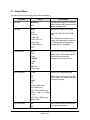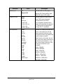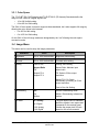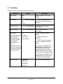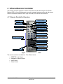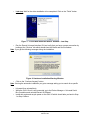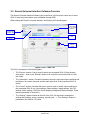
1
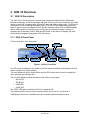
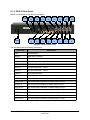
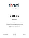
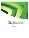
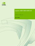
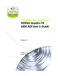
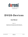
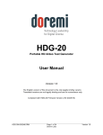
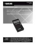
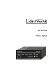
GHX-10
User Manual
Version 2.2
Compliant with GHX-10 Firmware version 1.4.0
and Doremi Universal Interface version 4.0.2
GHX.OM.000510.DRM
Page 1
Doremi Labs
Version 2.2
Table Of Contents
1 Introduction............................................................................................................................ 5
1.1 Contact Information........................................................................................................... 5
2 GHX-10 Overview...................................................................................................................6
2.1 GHX-10 Description........................................................................................................... 6
2.1.1 GHX-10 Front Panel...................................................................................................6
2.1.2 GHX-10 Rear Panel....................................................................................................7
2.2 Supported Formats............................................................................................................8
3 GHX-10 Front Panel Controller.............................................................................................9
3.1 Menu Items Overview........................................................................................................9
3.2 Input Menu...................................................................................................................... 10
3.3 Output Menu.................................................................................................................... 11
3.3.1 Color Space.............................................................................................................. 14
3.4 Image Menu.................................................................................................................... 14
3.5 Sync Menu...................................................................................................................... 15
3.6 Audio Menu..................................................................................................................... 15
3.7 OSD Menu....................................................................................................................... 17
3.8 System Menu.................................................................................................................. 18
3.9 Status Menu.................................................................................................................... 18
4 Infrared Remote Controller ................................................................................................19
4.1 Remote Controller Overview............................................................................................19
4.2 Remote Controller Functions...........................................................................................20
4.3 Quick Input Format Setting..............................................................................................21
4.4 Output Format Setting ....................................................................................................21
4.4.1 HDMI/DVI Output Format.........................................................................................21
4.4.2 SDI Output Format...................................................................................................21
5 Doremi Universal Interface Software (duis).......................................................................22
5.1 Doremi Universal Interface Software Installation.............................................................22
5.2 Doremi Universal Interface Software Overview...............................................................24
5.3 Settings Window.............................................................................................................. 25
5.4 Tabs Description............................................................................................................. 26
5.4.1 Input Tab..................................................................................................................26
5.4.2 Output Tab............................................................................................................... 26
5.4.3 Image Tab................................................................................................................27
5.4.4 Sync I/O Tab............................................................................................................. 28
5.4.5 Audio Tab................................................................................................................. 29
5.4.6 OSD Tab..................................................................................................................30
5.4.7 System Tab..............................................................................................................31
6 Firmware Update.................................................................................................................. 32
6.1 USB Update.................................................................................................................... 32
6.2 SD Memory Update......................................................................................................... 32
7 Annex A: Specifications......................................................................................................33
7.1 Inputs.............................................................................................................................. 33
7.2 Outputs............................................................................................................................ 33
GHX.OM.000510.DRM
Page 2
Doremi Labs
Version 2.2
7.3 Audio............................................................................................................................... 33
7.4 Video............................................................................................................................... 34
8 Acronyms............................................................................................................................. 35
9 Document Revision History................................................................................................36
GHX.OM.000510.DRM
Page 3
Doremi Labs
Version 2.2
Software License Agreement
The software license agreement can be found at the following location:
http://www.doremilabs.com/support/proav-support/proav-warranties/
Hardware Warranty
The hardware warranty can be found at the following location:
http://www.doremilabs.com/support/proav-support/proav-warranties/
HDMI
The terms HDMI and HDMI High-Definition Multimedia Interface, and the HDMI Logo are
trademarks or registered trademarks of HDMI Licensing LLC in the United States and other
countries.
GHX.OM.000510.DRM
Page 4
Doremi Labs
Version 2.2
1 Introduction
This document provides guidance on how to use the GHX-10 device. It explains the front panel,
the infrared remote control, and the Doremi Universal Interface usage. It also details how to
upgrade the firmware on the GHX-10.
1.1 Contact Information
If in need of help or assistance, please contact Doremi Labs Technical Services at
+ 1-818-562-1101 or email at [email protected].
GHX.OM.000510.DRM
Page 5
Doremi Labs
Version 2.2
2 GHX-10 Overview
2.1 GHX-10 Description
The GHX-10 is a Universal Cross Converter that incorporates High-Definition Multimedia
Interface technology, and SDI connectors that allow for any input to be converted to any output
format or scan rate. It supports both SD and HD video and employs high quality 12 bit bi-cubic
interpolation to ensure the highest quality picture. The GHX-10 can tackle many conversion
tasks. It can be used as a computer DVI to HD-SDI converter (using a DVI to HDMI® adapter
cable), HDMI resolution converter, or as an HD video up-converter or down-converter. It
supports up to 8 channels of AES, HDMI and SDI audio. A two lines LCD display and scroll
wheel simplify navigation through the GHX-10's menus.
2.1.1 GHX-10 Front Panel
This is a snap shot of the front panel:
Menu Wheel
SD Card
Signal LEDs
Escape Button
Power LED
Infrared Sensor
Power Switch
Figure 1: GHX-10 Front View
An LCD screen is available in the middle of the front panel to facilitate controlling the GHX-10
without using the On Screen Display.
The scroll wheel with built in Select button and the ESC button can be used to navigate the
menu structure and setup the unit.
The four LED indicators reflect the status of the various input signals:
•
SDI-A LED
•
SDI-B LED
•
HDMI LED
• SYNC LED
The “PWR” LED lights up when the GHX-10 is powered ON.
The infra-red sensor can be used to remotely control of the GHX-10, see Section 4.
A SD Memory connector is available and can be used to perform firmware update.
GHX.OM.000510.DRM
Page 6
Doremi Labs
Version 2.2
2.1.2 GHX-10 Rear Panel
Below is a snap shot of the GHX-10 rear panel:
USB
Power
HDMI
out
SDI-B
out
SDI-A
out
SYNC AES-12 AES-34 AES-56 AES-78
out
out
out
out
out
HDMI
in
SDI-B
in
SDI-A
in
SYNC AES-12 AES-34 AES-56 AES-78
in
in
in
in
in
Figure 2: GHX-10 Rear Panel
The rear panel has the following connectors:
Connector
Description
USB
USB connector
HDMI in
HDMI input connector
HDMI out
HDMI output connector
SDI-A out
SDI output connector – Link A
SDI-B out
SDI output connector – Link B
SDI-A in
SDI input connector – Link A
SDI-B in
SDI input connector – Link B
SYNC in
Sync input connector
SYNC out
Sync output connector
AES-12 in
AES audio input connector for audio tracks 1 and 2
AES-12 out
AES audio output connector for audio tracks 1 and 2
AES-34 in
AES audio input connector for audio tracks 3 and 4
AES-34 out
AES audio output connector for audio tracks 3 and 4
AES-56 in
AES audio input connector for audio tracks 5 and 6
AES-56 out
AES audio output connector for audio tracks 5 and 6
AES-78 in
AES audio input connector for audio tracks 7 and 8
AES-78 out
AES audio output connector for audio tracks 7 and 8
GHX.OM.000510.DRM
Page 7
Doremi Labs
Version 2.2
2.2 Supported Formats
The table below summarizes all supported inputs and outputs available on the GHX-10.
Supported Input(s)
Supported Output(s)
SD-SDI: NTSC, PAL
SD-SDI: NTSC, PAL
HD-SDI: all HD +2K formats (SMPTE
274, SMPTE296, SMPTE372)
HD-SDI: all HD +2K formats (SMPTE
274, SMPTE296, SMPTE372)
HDMI/DVI:
HDMI/DVI:
640x480
= VGA
640x480
= VGA
720x480i
= 480i
720x480i
= 480i
720x480p
= 480p
720x480p
= 480p
1440x480i
= 480i
720x576i
= 576i
720x576i
= 576i
720x576p
= 576p
720x576p
= 576p
800x600
= SVGA
1440x576i
= 576i
1280x720
= 720p
800x600
= SVGA
1024x768
= XGA
1280x720
= 720p
1366x768
= WXGA
1024x768
= XGA
1280x1024
= SXGA
1280x768
= WXGA
1400x1050
= SXGA+
1364x768
= WXGA
1680x1050
= WSXGA+
1366x768
= WXGA
1920x1080i
= 1080i
1536x768
= 1536x768
1152x864
= XGA+
1280x960
= SXGA-
1280x1024
= SXGA
1364x1024
= 1364x1024
1400x1050
= SXGA+
1680x1050
= WSXGA+
1920x1080i
= 1080i
1920x1080p
= 1080p
2048x1080
= 2Kp
1600x1200
= UXGA
1920x1200
= WUXGA
GHX.OM.000510.DRM
1920x1080p = 1080p
1920x1200
Page 8
Doremi Labs
= WUXGA
Version 2.2
3 GHX-10 Front Panel Controller
Throughout this chapter “press Select” refers to pressing the front panel scroll wheel button of
the GHX-10 – see Figure 1.
3.1 Menu Items Overview
Press “Select” to enter the GHX-10 menu system then turn the “Wheel” to access the different
menus:
•
Input
•
Output
•
Image
•
Sync
•
Audio
•
OSD
•
System
•
Status
Press “Select” to navigate one of the above menu items and access the list of available submenus. Browse the list of available sub-menus by turning the “Wheel”, then press “Select” to
change settings of a given sub-menu.
Browse the available values by turning the “Wheel”. To choose the desired value, press
“Select”. The selected value should be flagged with the # sign on its right which is the current
setting indicator.
To go back to a higher level in this menu tree, press on the “ESC” button – Keep pressing it to
exit the menu system.
The following tables list all GHX-10 setup parameters, items in bold are factory defaults. All
video formats show frame rates and not the field rates, so 1080i-60 fields per second will be
shown as 1080i-30 frames per second.
GHX.OM.000510.DRM
Page 9
Doremi Labs
Version 2.2
3.2 Input Menu
This menu can be used to setup the input parameters.
Sub-Menu
Interface
SDI Color
Value
Description
SDI
Input interface setting.
HDMI/DVI
Pattern
Pattern produces a color pattern
with 16 channels of audio at
different frequencies
Auto
SDI input color setting.
RGB
Auto: Single Link (1.5Gbps) inputs
will be treated as 601 (SD) or 709
(HD). Dual link (1.5Gbps) inputs
will be treated as RGB.
RGB ext
YCbCr 601
YCbCr 601 ext
Ext: designates extended color
range (full bandwidth) as opposed
to limiting the color spectrum to
comply with ITU standards.
YCbCr 709
YCbCr 709 ext
XYZ’
YCxCz'
HDMI/DVI color
Auto
HDMI/DVI input color setting
RGB
Auto: Detected using meta-data, if
not present the default is RGB
RGB ext
YCbCr 601
Ext: designates extended color
range (full bandwidth) as opposed
to limiting the color spectrum to
comply with ITU standards.
YCbCr 601 ext
YCbCr 709
YCbCr 709 ext
Default EDID
720p 50
DVI input default setting.
720p 60
When you feed a signal to the
HDMI input, the GHX-10 has to
report a native resolution over
EDID. This menu allows the user
to change the default resolution of
the GHX-10 between the
available formats.
1080i 25
1080i 30
1080p 50
1080p 60
WUXGA 50
CAUTION: You must disconnect
HDMI/DVI source before
changing this setting.
WUXGA 60
GHX.OM.000510.DRM
Page 10
Doremi Labs
Version 2.2
3.3 Output Menu
This menu can be used to setup the output parameters.
Sub-Menu
Interface
SDI color
Value
HDMI/DVI
Description
SDI
Set the active output. For common
video formats, both outputs can be
active simultaneously
Auto
Set the SDI output color mode
RGB
Auto: 601 (SD) 709 (HD), RGB
(2K)
RGB ext
YCbCr 601
“ext” designates extended color
range (full bandwidth) as opposed
to limiting the color spectrum to
comply with ITU standards.
YCbCr 601 ext
YCbCr 709
YCbCr 709 ext
XYZ’
SDI Resolution
NTSC
Set the SDI output pixel resolution.
PAL
Match Input: In this mode, the SDI
output will have the same
resolution as the input source.
720p
1080i/sf
1080p
2Kp
2Kp Flat
Match Input
SDI Frequency
23.98
Set the SDI output frame rate
24
Match Input: In this mode, the SDI
output frame rate will be equivalent
to the input source
25
29.97
30
47.95 (1080p only)
48 (1080p only)
50 (720p & 1080p only)
59.94 (720p & 1080p
only)
60 (720p & 1080p only)
Match input
SDI Force Interl
Off
Force the SDI output to interlaced
(or Segmented Frame)
On
GHX.OM.000510.DRM
Page 11
Doremi Labs
Version 2.2
Sub-Menu
Ancillary out
HDMI/DVI color
Value
Off
Off: No VANC on SDI output
Bypass SDI
Bypass SDI: Pass Ancillary data
from SDI input to SDI output
Auto
Set the HDMI/DVI output colors
RGB
Auto: RGB unless otherwise
communicated over EDID.
RGB ext
YCbCr 601
“ext” designates extended color
range (full bandwidth) as opposed
to limiting the color spectrum to
comply with ITU standards.
YCbCr 601 ext
YCbCr 709
YCbCr 709 ext
DVI Resolution
Description
Auto
Set the DVI output pixel resolution.
VGA
Auto: In this mode, the unit will
read the default resolution of the
connected monitor using EDID and
sets the output to match
SVGA
XGA
WXGA
480p
Match Input: In this mode, the unit
will set the DVI output resolution to
match the input resolution – or to
the closest output resolution if the
exact input resolution is not
available.
480i
VGA= 640x480
576p
SVGA= 800x600
576i
XGA= 1024x768
720p
WXGA= 1280x800
1080i
SXGA= 1280x1024
1080p
SXGA+= 1400x1050
Match input
WSXGA+= 1680x1050
SXGA
SXGA+
WSXGA+
WUXGA
WUXGA= 1920x1200
GHX.OM.000510.DRM
Page 12
Doremi Labs
Version 2.2
Sub-Menu
DVI Frequency
Value
Auto
Set the DVI output frequency .
23.98
This list shows all possible
frequencies but the GHX-10 menu
will only show the allowed
frequencies for the DVI output
format selected.
24
25
29.97
30
Auto: In this mode, the unit will
read the default frequency of the
connected monitor using EDID and
sets the output to match
47.95
48
50
59.94
Match Input: In this mode, the unit
will set the DVI output frequency to
match the input resolution.
60
Match input
Color Depth
Match input *2
Match input *2: The output is set at
double the input frame rate.
Auto
Set the color depth
8 bits
Note: If the input is 10bit and the
output is set to 8bit for
example, the GHX-10 will
dither (NOT truncate)
10 bits
12 bits
Time Code
Description
Off
Off: No embedded timecode on
SDI output
Bypass SDI
Bypass SDI: Pass embedded
timecode from SDI input to SDI
output
Free wheel
Free wheel: Generate embedded
Time Code starting at the moment
this option is enabled.
GHX.OM.000510.DRM
Page 13
Doremi Labs
Version 2.2
3.3.1 Color Space
The ITU-R BT.709-5 (HD formats) and ITU-R BT.601-5 (SD formats) Standards define the
range of color values in a digital signal to be:
• 16 to 240 for 8bit coding
• 64 to 960 for 10bit coding
The GHX-10 color space conversion supports these standards, but it also supports full range by
allowing the color values to be between:
• 0 to 255 for 8bit coding
• 0 to 1023 for 10bit coding
On the GHX-10 the full range modes are designated by the “ext” following the color space
conversion mode.
3.4 Image Menu
This menu can be used to setup the image parameters.
Sub-Menu
Value
Description
Brightness
0% to 100% default 50%
Brightness value setting
Contrast
0% to 100% default 50%
Contrast value setting
Scaling
One to One
Scaling value setting
Aspect Ratio
Aspect Ratio: Maintain input
aspect ratio
Fill
Aspect Fit H
Fill: Scale to fill the output
resolution
Aspect Fit V
Aspect Fit H (V): Scale
Horizontally (Vertically) to fill the
output resolution
One to One: No Scaling
Deinterlacing
Off
Set the Deinterlacing mode
On
Motion: Deinterlacing is based on
motion.
Motion
SD Ratio
4:3 Analog
The pixel aspect ratio for standard
definition signals is not square and
it depends on the material used.
Choose the proper pixel SD ratio
based on the source material.
4:3 Digital
16:9 Analog
16:9 Digital
GHX.OM.000510.DRM
Page 14
Doremi Labs
Version 2.2
Sub-Menu
Input LUT
Value
User Defined
0.1 to 4.0 default 1.0
Output LUT
User Defined
0.1 to 4.0 default 1.0
Description
Set the Gamma Curve from 0.1 to
4.0 or choose User Defined to use
a custom LUT table uploaded
using Doremi Universal Software
Interface
Set the Gamma Curve from 0.1 to
4.0 or choose User Defined to use
a custom LUT table uploaded
using Doremi Universal Software
Interface
3.5 Sync Menu
This menu can be used to setup the sync parameters.
Sub-Menu
Input
Value
Auto
Sync input setting
SDI
Auto: Sync is derived from the
input source
HDMI/DVI
Extern
Output
Description
Extern: Sync is derived from the
Sync Input connector.
Auto
Sync output setting
Force Bi-Level
Auto: Tri-Level for HD and 2K
formats and Bi-Level for SD
formats.
H offset
X pixels default 0
Horizontal Sync offset in pixels
V offset
X lines default 0
Vertical Sync offset in lines
3.6 Audio Menu
This menu can be used to setup the audio parameters.
Sub-Menu
Input
Value
Description
Auto
Audio input format setting
SDI
Auto: Audio input is the same as
video input
DVI/HDMI
AES
Delay
GHX.OM.000510.DRM
X frames default 0
Page 15
Doremi Labs
Audio delay setting from -1 to +2
frames
Version 2.2
Sub-Menu
Value
Description
Level
-18, -12, -6, 0, +6, +12,
+18 dB
Audio Output level setting
HDMI Channel out
Auto
Set the HDMI audio output mode
2
Auto: All audio inputs will be
present on the HDMI output
4
6
2, 4, 6, 8: Total number of audio
channels to be present on the
HDMI output
8
Off
Off: No audio on HDMI output
SDI Out Groups
Auto
Set the embedded SDI active
audio groups
1
1+2
Auto: All audio inputs will be
present on the SDI output
1+2+3
1+2+3+4
Each group has 4 audio channels,
when 1+2+3+4 is selected, all 16
audio channels will be present.
Off
Swap Audio
Channels 3 and 4
GHX.OM.000510.DRM
Off: No embedded audio on SDI
output
Channels 3 and 4, commonly used
for sub-woofer and central channel
can be swapped if needed.
On
Off
Page 16
Doremi Labs
Version 2.2
3.7 OSD Menu
This menu can be used to setup the OSD parameters.
Sub-Menu
OSD Enable
Value
Yes
Description
Enable or disable On Screen
Display
No
OSD timeout
X s (seconds) default On Screen Display timeout in
30s
seconds. Set to Infinite to keep it
always on.
Infinite
OSD H Position
1% to 99% default 25%
OSD horizontal position in
percentage
OSD V position
1% to 99% default 25%
OSD vertical position in
percentage
OSD Status
Off
The OSD Status will
show the burn-in
window timecode,
I/O status and audio
levels when the
menu OSD is not
active.
TC BIW
Burn In Window and Status
display
Input Status
- Off: BIW and Status not
displayed
Output Status
- TC BIW: Timecode is shown in
a burn-in window on the GHX
output
- Input Status: In addition to the
BIW timecode, the GHX output
will display the Input Status
including Audio levels, Closed
Caption presence, Input Format
and CRC errors (flashing red dot)
OSD Status Position
can only be set using
the Doremi Universal
Interface Software
- Output Status: In addition to the
BIW timecode, the GHX output
will display the Output Status.
OSD/TC Color
White/Black
Burn In Window type setting
W/B Zoom
Black/White
B/W Zoom
GHX.OM.000510.DRM
Page 17
Doremi Labs
Version 2.2
3.8 System Menu
This menu allows to access the system parameters.
Sub-Menu
Save
Description
Save current settings to flash.
Select to Save, when you get the “?”
Select again to confirm, you should see
“#”
Firmware: v.x.y
Firmware version
Serial: zzzzzzz
Serial number
License: uuuuuuuu
License number
Temp: vv C
Temperature (in degree Celsius)
Standby
Standby mode. Put the unit in Power
Down mode
Auto Standby
Auto Standby mode. Set the idle time
duration before the unit goes in power
down mode automatically
Off, 60minutes,
120minutes
IR
0 to F default is 0
MicroSD or SD Memory
update
Infra-Red. To avoid IR interference when
you have multiple GHX units, you can
assign each a different IR code from 0x0
to 0xF (16 total). You need to set the DIP
switch on your Doremi IR remote
accordingly.
Depending on your unit, you might see
“Micro SD” or “SD Memory” firmware
update
3.9 Status Menu
This menu can be used to view the Input and Output status.
Sub-Menu
In:
Out:
GHX.OM.000510.DRM
Description
Input and Output format status
information
Page 18
Doremi Labs
Version 2.2
4 Infrared Remote Controller
The buttons on the IR remote are used to access the unit while observing the On Screen
Display (OSD). Left and Right arrows are used to navigate between menus and sub-menus.
Select is to make a selection, Exit is to go one level up or exit the menu structure.
4.1 Remote Controller Overview
“Reset” button
“IR Lock” button
“Up Arrow” button
“Select” button
“Right Arrow” button
“Left Arrow” button
“Down Arrow” button
“Menu” button
“Exit” button
Input Format Selection
“InFPS” button
Output Format area
“InRes” button
“Status OSD” button
“Save” button
“De-Int Filter” button
“Scaling” button
Figure 3: Infrared Remote Controller
The remote controller is divided into Four different areas:
•
RESET/IR Lock buttons
•
Navigation or Menu System
•
Input Format
•
Output format
GHX.OM.000510.DRM
Page 19
Doremi Labs
Version 2.2
4.2 Remote Controller Functions
Remote Control
Input format selection
Function
Select HD-SDI, SDI, HDMI/DVI (through the DVID/HDMI button) or Pattern
Note: The DVI-A button is not used.
“IR Lock” button
Not used
“RESET” button
Not used
“Menu” button
Invoke the Menu System. Pressing this button on the IR
is similar to pressing the scroll button on the GHX-10
front panel
“Exit” button
Back one menu level. Similar to Front Panel ESC
button
Output format area
Set the SDI or HDMI/DVI output resolution to:
HDMI/DVI: Auto, 720p, 1080i, 1080p, 1024x768,
1280x768, 1366x768, 1280x1024, 1920x1200
SDI: 480i, 576i, 720p, 1080i, 1080p
“Up Arrow” button
Not used
“Down Arrow” button
Not used
“Left Arrow” button
Navigate left. Similar to Wheel counter clockwise
“Right Arrow” button
Navigate right. Similar to Wheel clockwise
“Select” button
Ok/Select, Similar to Select on Front Panel
“InRes” buttons
Force the output resolution to match the input
resolution. There is one for SDI and one for HDMI/DVI
“InFPS” buttons
Force the output frame rate to match the input frame
rate. There is one for SDI and one for HDMI/DVI
“Scaling” button
Navigate between the available scaling options
“De-Int Filter” button
Toggle De-interlacing Filter ON or OFF
“Status OSD” button
Toggle on screen display ON and OFF
“Save” button
Save settings
OUT-HDM
Set the output interface to HDMI/DVI
OUT-SDI
Set the output interface to SDI
GHX.OM.000510.DRM
Page 20
Doremi Labs
Version 2.2
4.3 Quick Input Format Setting
To select the input format, press one of the buttons available at the top of the remote controller.
Press one of the
available input formats
Figure 4: Quick Input Format Setting
You have the choice between: SDI, HDMI (using the DVI-D/HDMI button) and Pattern. The
“Pattern” button will generate color bars with 16 channels of audio at different frequencies.
Note: The DVI-A button is unused.
4.4 Output Format Setting
Since not all formats are common between SDI and HDMI/DVI, the output interface must be
selected.
•
If the output interface is set to SDI and if the selected output format is a valid HDMI
resolution, both SDI and HDMI outputs will be active with proper colors on both outputs.
This is due to the presence of a dedicated color space converter on the HDMI output.
•
If the output interface is set to DVI (HDMI) and if the selected output format is a valid SDI
resolution, both HDMI and SDI outputs will be active but the SDI output colors might be
wrong. This is due to the presence of a dedicated color space converter on the SDI
output (this might change in future releases).
4.4.1 HDMI/DVI Output Format
To set the output format to a specific HDMI/DVI format, press “OUT-HDM” on the IR controller,
then press the corresponding output format: Auto, 720p, 1080i, 1080p, 1024x768, 1280x768,
1366x768, 1280x1024, 1920x1200. More formats are available through the menu system.
4.4.2 SDI Output Format
To set the output format to a specific SDI format, press “SDI-OUT” on the IR controller, then
press the format you want to set: 480i, 576i, 720p, 1080i, 1080p. More formats are available
through the menu system.
GHX.OM.000510.DRM
Page 21
Doremi Labs
Version 2.2
5 Doremi Universal Interface Software (duis)
5.1 Doremi Universal Interface Software Installation
To install the Doremi Universal Interface software, follow the steps below:
1. Plug the provided USB cable between the GHX-10 and an available USB port on your PC see Figure 2 for USB connector location
2. Power on the GHX-10 by pressing the PWD button
3. If you get the "Found New Hardware Wizard" window at this stage, click “Cancel”
4. Run the installation package by double-clicking on a file like
“Doremi_Universal_Interface_Software-4.0.2.0.exe” which can be downloaded from our web
site: http://www.doremilabs.com/.
5. After the installation is over, if you get the "Found New Hardware Wizard", go through all the
steps shown below:
•
Step 1: Select the “No, not this time” option and click on “Next >”
Figure 5: ”Found New Hardware Wizard” Window – Step 1
•
Step 2: When asked for software installation, choose the option “Install the software
automatically (recommended)”
Figure 6: ”Found New Hardware Wizard” Window – Step 2
GHX.OM.000510.DRM
Page 22
Doremi Labs
Version 2.2
•
Last step: Wait for the driver installation to be completed. Click on the “Finish” button
when done.
Figure 7: ”Found New Hardware Wizard” Window – Last Step
•
Run the Doremi Universal Interface GUI and verify that you have a proper connection by
looking at the “Devices” tab which should show the Model and Serial numbers.
Note: If you get the following message during the installation:
Figure 8: Hardware Installation Warning Window
•
Click on the “Continue Anyway” button.
Note: If during the automatic installation you get a message asking you to search for a specific
file,
•
•
•
Hit cancel then uninstall duis.
While the GHX-10 unit is still connected, go to the Device Manager > Universal Serial
Bus Controllers and uninstall Doremi GhX Board.
Install duis again and recycle power on the GHX-10 which should take you back to Step
1 or Step 2 above.
GHX.OM.000510.DRM
Page 23
Doremi Labs
Version 2.2
5.2 Doremi Universal Interface Software Overview
The Doremi Universal Interface Software (duis) consists of a GUI that can control one or more
GHX-10 device(s) connected to your workstation through USB.
When starting the Doremi Universal Interface, the following GUI should appear:
List-box button
to use to select
one connected
GHX-10
“Settings file
filename” field
Informative
area
“Devices”
window
“Input
selection”
window
Figure 9: duis – Input Tab
This GUI is composed of the following parts:
•
The “Devices” section: Can be used to select one connected GHX-10 from the drop
down menu – click on the “Refresh” button to be sure all the connected GHX-10 units
are visible.
•
The “Information” section: Provides information about the input and output interfaces and
resolutions, the current timecode and the audio input level of the connected GHX-10
device.
•
The “Control” section: Has tabs that can be used to view or modify various settings on
the connected GHX-10 unit: Input settings, Output settings, Image settings, Sync I/O
settings, Audio settings, OSD (On Screen Display) settings and System settings. These
tabs are presented in Section 5.4 .
•
The “Settings” window located on the left of the GUI: Can be used to manage the
settings files (loading, saving, importing, exporting etc …). This “Settings” window is
presented in the Section 5.3 below.
GHX.OM.000510.DRM
Page 24
Doremi Labs
Version 2.2
5.3 Settings Window
The “Settings” window can be used to manage settings files
•
To save the current duis settings into a file, enter a settings filename in the top left
corner field as shown in below, then click on “Save”.
The saved settings file should appear in the “Settings” window:
“Settings file”
saved
“Settings files”
area
“Load” button
“Save” button
“Delete” button
“Import” button
“Export” button
“Update”
button
Figure 10: duis – Settings Section
•
To export this saved “settings file” so you can use it for another GHX-10 device, select it
in the “Settings files” area – see figure above – and click on the “Export” button. You
should be asked to confirm where you want to export this file using a standard “Save as”
dialog box.
•
To import an existing “settings file” from a .ghx file to the connected unit click on the
“Import” button. Then browse the files to select the appropriate “settings file” you want to
import. The imported file should appear in the “Settings files” area on the left part of the
GUI. To apply the settings to the connected GHX-10 unit, you need to select this file
then click on the “Load” button. The GHX-10 settings should be updated.
•
To delete a settings file present in the “Settings files” area – see figure above – select it
and click on the “Delete” button.
•
Click on the “Update” button to update the “Settings” window to reflect the content of the
“User Settings” folder of the duis (folder where all the settings files are stored).
GHX.OM.000510.DRM
Page 25
Doremi Labs
Version 2.2
5.4 Tabs Description
5.4.1 Input Tab
The input tab is presented in Figure 9 above. All parameters are explained earlier in this manual
in the chapter titled “GHX-10 Menu”.
5.4.2 Output Tab
Below is a screen shot of the “Output Tab”:
“Output
selection”
window
“HDMI/DVI out
selection”
window
“SDI out
selection”
window
Figure 11: duis – Output Tab
All parameters are explained earlier in this manual in the Section 3 titled, “GHX-10 Front Panel
Controller.”
GHX.OM.000510.DRM
Page 26
Doremi Labs
Version 2.2
5.4.3 Image Tab
This is a screen shot of the “Image Tab”:
Brightness
related
“Reset”
button
Brightness
cursor
Contrast
cursor
Figure 12: duis – Image Tab
All parameters are explained earlier in this manual in the Section 3 titled, “GHX-10 Front Panel
Controller.”
GHX.OM.000510.DRM
Page 27
Doremi Labs
Version 2.2
5.4.4 Sync I/O Tab
Below is a screen shot of the “Sync I/O Tab”:
“Input Sync
Reference”
window
“Output Sync
Format”
window
“Sync V
offset” cursor
“Sync H
offset” cursor
Figure 13: duis – Sync I/O Tab
All parameters are explained earlier in this manual in the Section 3 titled, “GHX-10 Front Panel
Controller.”
GHX.OM.000510.DRM
Page 28
Doremi Labs
Version 2.2
5.4.5 Audio Tab
This is a screen shot of the “Audio Tab”:
Figure 14: duis – Audio Tab
All parameters are explained earlier in this manual in the Section 3 titled, “GHX-10 Front Panel
Controller.”
GHX.OM.000510.DRM
Page 29
Doremi Labs
Version 2.2
5.4.6 OSD Tab
Below is a screen shot of the “OSD Tab”:
“OSD
Timeout”
cursor
Figure 15: duis – OSD Tab
All parameters are explained earlier in this manual in the Section 3 titled, “GHX-10 Front Panel
Controller.”
The Status Window Vertical and Horizontal positions are available only through duis. They set
the position of the Status OSD window that shows only when the main OSD is off and the
Status OSD is ON.
GHX.OM.000510.DRM
Page 30
Doremi Labs
Version 2.2
5.4.7 System Tab
This is a screen shot of the “System Tab”:
“Restore
Default
Settings”
button
“Save Settings”
button
“Enter New
License
Number”
button
“Firmware
upgrade”
button
“Display
Logs”
button
GHX-10
temperature
Figure 16: duis – System Tab
All parameters are explained earlier in this manual in the Section 3 titled, “GHX-10 Front Panel
Controller.”
In addition this tab can be used to perform the following actions:
•
To save the current settings to flash, click on the “Save Settings” button
•
To restore the factory default settings, click on the “Restore Default Settings” button
•
To enter a new license number, click on the “Enter New License Number ...” button and
type the new license number in the pop-up window.
•
To perform a firmware upgrade, click on the “Firmware upgrade (Current: x.yy)” button –
note that this button provides the current firmware version installed on the connected
unit, after “Current: ”. On the above picture, the current firmware is version 1.2.15 for
example. See Section 6.1 for detailed upgrade steps to follow.
•
To display the logs, click on the “Display Logs” button. A window containing the logs will
appear. Select “Auto Update” from that window to see all messages.
GHX.OM.000510.DRM
Page 31
Doremi Labs
Version 2.2
6 Firmware Update
The firmware can be updated through USB or SD Memory. This section presents both methods.
In case you miss one of the files listed in the procedures below, please contact Doremi Labs
(see Section 1.1).
6.1 USB Update
The firmware can be updated through USB using the Doremi Universal Interface Software as
presented in Section 5.4.7 .
To perform such update, follow the steps below:
1. Connect the GHX-10 to your computer using the USB cable provided with the unit,
2. Start the Doremi Universal Interface Software – see Section 5
3. Go to the “System Tab” - see Section 5.4.7
4. Click on the “Firmware upgrade” button
5. Select the firmware file (e.g: “ghx_firmware_1.3.11.bin”) and click on the “Upgrade now”
button
Figure 17: Firmware Update Window
6. Once the update is completed, re-cycle power on the GHX-10 unit. Newer GHX-10
models recycle power on their own.
6.2 SD Memory Update
The SD Memory must be formatted as FAT or FAT32.
This is the update procedure:
1. Copy the firmware file (e.g: “ghx_firmware_1.3.11.bin”) on the SD Memory card
2. Plug the SD Memory into the SD port of the GHX-10 (see Figure 2).
3. Power On the GHX-10 and go to the menu “System” – see section 3.8
4. Select the “SD Memory update” sub-menu.
5. Select the file you want to use for the update - using the menu scroll wheel, see Figure 1
- and confirm the update.
6. Once the update is completed, re-cycle power on the GHX-10 unit. Newer GHX-10
models recycle power automatically.
GHX.OM.000510.DRM
Page 32
Doremi Labs
Version 2.2
7 Annex A: Specifications
7.1 Inputs
•
HDMI without HDCP
•
Single or Dual Stream HDSDI (For dual stream HDSDI, the two inputs must comply with
SMPTE Standard S372M, i.e., genlocked with no more than 2 to 3 pixels of difference)
7.2 Outputs
•
Single or Dual Stream HDSDI
•
Single HDMI Output without HDCP
7.3 Audio
•
16 channels of audio supported embedded in HDSDI
•
8 channels using HDMI
•
8 channels of AES audio de-embedded
•
Audio delay can be set from the GUI, front panel or IR Remote Control -1 to +2 frames
GHX.OM.000510.DRM
Page 33
Doremi Labs
Version 2.2
7.4 Video
Supported Input(s)
Supported Output(s)
SD-SDI: NTSC, PAL
SD-SDI: NTSC, PAL
HD-SDI: all HD +2K formats
(SMPTE 274, SMPTE296,
SMPTE372)
HD-SDI: all HD +2K formats (SMPTE 274,
SMPTE296, SMPTE372)
HDMI/DVI:
HDMI/DVI:
640x480
=
VGA
720x480i
=
480i
720x480p
=
480p
1440x480i
=
480i
720x576i
=
576i
720x576p
=
576p
1440x576i
=
576i
800x600
=
SVGA
1280x720
=
720p
1024x768
=
XGA
1280x768
=
WXGA
1364x768
=
WXGA
1366x768
=
WXGA
1536x768
=
1536x768
1152x864
=
XGA+
1280x960
=
SXGA-
1280x1024
=
SXGA
1364x1024
=
1364x1024
1400x1050
=
SXGA+
1680x1050
=
WSXGA+
1920x1080i =
1080i
1920x1080p =
1080p
2048x1080
=
2Kp
1600x1200
=
UXGA
1920x1200
=
WUXGA
GHX.OM.000510.DRM
Page 34
Doremi Labs
640x480
=
VGA
720x480i
=
480i
720x480p
=
480p
720x576i
=
576i
720x576p
=
576p
800x600
=
SVGA
1280x720
=
720p
1024x768
=
XGA
1366x768
=
WXGA
1280x1024
=
SXGA
1400x1050
=
SXGA+
1680x1050
= WSXGA+
1920x1080i =
1080i
1920x1080p =
1080p
1920x1200
WUXGA
=
Version 2.2
8 Acronyms
Term
DVI
HDMI
HD-SDI
IR
GHX.OM.000510.DRM
Definition
Digital Visual Interface
High-Definition Multimedia Interface
High Definition Serial Digital Interface
Infra Red
OSD
On Screen Display
SDI
Serial Digital Interface
Page 35
Doremi Labs
Version 2.2
9 Document Revision History
Date
Version
10/31/2008
1.0
First version.
11/10/2008
1.2
Editorial changes.
12/11/2008
1.3
GHX Control Panel GUI documented.
04/09/2009
1.4
All sections revised.
04/10/2009
1.5
All sections revised.
09/09/2010
1.6
All sections revised and modified. Old images updated
to reflect current version of the Doremi Universal
Interface Software. New picture of the IR Doremi
remote updated.
10/22/2010
1.7
Section 3.6.1 added to reflect supported audio sample
rates.
03/02/2011
1.8
New pictures added.
03/04/2010
2.0
Updated to comply with GHX-10 firmware version 1.4.0
and Doremi Universal Interface version 4.0.2.
07/26/2012
2.1
Logo updated and contact information added.
02/12/2013
2.2
Minor revisions made to Section 1 and Section 2.1.
GHX.OM.000510.DRM
Description
Page 36
Doremi Labs
Version 2.2