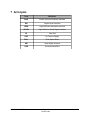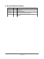
1
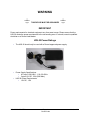
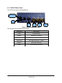
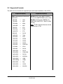
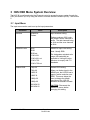
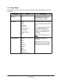
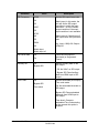
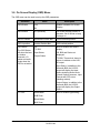
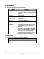
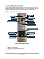
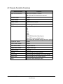
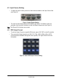
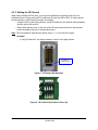
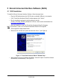
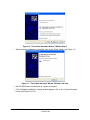
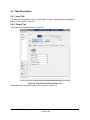
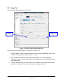
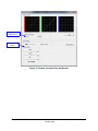
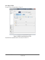
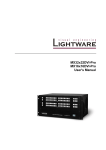
H2S-30
User Manual
Version 1.3
Compliant with H2S-30 Firmware version 1.6.0
and H2S-30 Doremi Universal Interface Software 4.2.3
H2S.OM.001539.DRM
Page 1
Doremi Labs
Version 1.3
Table Of Contents
1 Introduction............................................................................................................................ 8
1.1 Purpose............................................................................................................................. 8
1.2 Software Version...............................................................................................................8
1.3 Contact Information........................................................................................................... 8
2 H2S-30 Overview.................................................................................................................... 9
2.1 H2S-30 Description........................................................................................................... 9
2.1.1 H2S-30 Top View.......................................................................................................9
2.1.2 H2S-30 Front Panel....................................................................................................9
2.1.3 H2S-30 Rear Panel..................................................................................................10
2.2 Supported Formats.......................................................................................................... 11
3 H2S OSD Menu System Overview......................................................................................12
3.1 Input Menu...................................................................................................................... 12
3.2 Output Menu.................................................................................................................... 13
3.2.1 Color Space.............................................................................................................. 15
3.3 Image Menu.................................................................................................................... 15
3.4 Sync Menu...................................................................................................................... 17
3.5 Audio Menu..................................................................................................................... 18
3.5.1 Supported Audio Sample Rates................................................................................18
3.6 On Screen Display (OSD) Menu......................................................................................19
3.7 System Menu.................................................................................................................. 20
3.8 Status Menu.................................................................................................................... 20
4 Infrared Remote Controller.................................................................................................21
4.1 Remote Controller Overview............................................................................................21
4.2 Remote Controller Functions...........................................................................................22
4.3 Input Source Setting........................................................................................................23
4.3.1 SDI Output Format...................................................................................................23
4.3.2 Setting the IR Channel..............................................................................................24
5 Doremi Universal Interface Software (DUIS)......................................................................25
5.1 DUIS Installation.............................................................................................................. 25
5.2 Doremi Universal Interface Software Overview...............................................................28
5.3 Settings Field................................................................................................................... 29
5.4 Tabs Description............................................................................................................. 31
5.4.1 Input Tab..................................................................................................................31
5.4.2 Output Tab............................................................................................................... 31
5.4.3 Image Tab................................................................................................................32
5.4.4 Sync I/O Tab............................................................................................................. 34
5.4.5 Audio Tab................................................................................................................. 35
5.4.6 OSD Tab..................................................................................................................36
5.4.7 System Tab..............................................................................................................37
6 Firmware Update.................................................................................................................. 39
6.1 USB Update.................................................................................................................... 39
7 Acronyms............................................................................................................................. 40
8 Document Revision History................................................................................................41
H2S.OM.001539.DRM
Page 2
Doremi Labs
Version 1.3
Software License Agreement
The software license agreement can be found at the following location:
http://www.doremilabs.com/support/proav-support/proav-warranties/
Hardware Warranty
The hardware warranty can be found at the following location:
http://www.doremilabs.com/support/proav-support/proav-warranties/
HDMI
The terms HDMI and HDMI High-Definition Multimedia Interface, and the HDMI Logo are
trademarks or registered trademarks of HDMI Licensing LLC in the United States and other
countries.
H2S.OM.001539.DRM
Page 3
Doremi Labs
Version 1.3
WARNING
THIS DEVICE MUST BE GROUNDED
IMPORTANT
Power requirements for electrical equipment vary from area to area. Please ensure that the
H2S-30 meets the power requirements in the surrounding area. If in doubt, consult a qualified
electrician or a Doremi Labs dealer.
H2S-30 Power Ratings
•
The H2S-30 should only be used with a Doremi approved power supply.
•
Power Supply Specifications:
• AC Input: 100-240V~, 1.2A, 50-60Hz
• Output 12V DC, 3.0A (36W Max.)
H2S-30 Power Requirements
• 12V DC, .12A
•
H2S.OM.001539.DRM
Page 4
Doremi Labs
Version 1.3
Protecting Yourself and the H2S-30
Never touch the AC plug with wet hands. Always disconnect the H2S-30 from the power supply
by pulling on the plug, not the cord. Allow only a Doremi Labs dealer or qualified professional
engineer to repair or re-assemble the H2S-30. Apart from voiding the warranty, unauthorized
engineers might touch live internal parts and receive a serious electric shock. Do not put, or
allow anyone to put any object, especially metal objects, into the H2S-30. Use only Doremi
approved power supply.
If water or any other liquid is spilled into or onto the H2S-30, disconnect the power and call a
Doremi dealer. The unit must be well ventilated and away from direct sunlight. To avoid damage
to internal circuitry, as well as the external finish, keep the H2S-30 away from direct sources of
heat (heater vents, stoves, radiators). Avoid using flammable aerosols near the H2S-30. They
can damage the surface area and may ignite. Do not use denatured alcohol, paint thinner, or
similar chemicals to clean the H2S-30. This can damage the unit.
Modification of this equipment is dangerous and can result in the functions of the H2S-30 being
impaired. Never attempt to modify the equipment in any way. In order to ensure optimum
performance of the H2S-30, select the setup location carefully and make sure the equipment is
used properly. Avoid setting up the H2S-30 in the following locations:
•
In a humid or dusty environment.
•
In a room with poor ventilation.
•
On a surface which is not level.
•
Inside a moving vehicle where it will be subject to vibration.
•
In an extremely hot or cold environment.
H2S.OM.001539.DRM
Page 5
Doremi Labs
Version 1.3
W A R N IN G !!
T o p re v e n t fire o r s h o c k h a z a rd , d o n o t e x p o s e th is a p p lia n c e to ra in o r m o is tu re
C A U T IO N
R IS K O F E L E C T R IC S H O C K
D O N OT O PEN
!
C A U T IO N :
T O R E D U C E T H E R IS K O F E L E C T R IC S H O C K ,
D O N O T R E M O V E C O V E R (O R B A C K ).
N O U S E R -S E R V IC E A B L E P A R T S IN S ID E .
R E F E R S E R V IC IN G T O Q U A L IF IE D S E R V IC E P E R S O N N E L .
T h e lig h tn in g fla s h w ith th e a rro w h e a d s y m b o l s u p e rim p o s e d
a c ro s s a g ra p h ic a l re p re s e n ta tio n o f a p e rs o n , w ith in a n e q u ila te ra l
tria n g le , is in te n d e d to a le rt th e u s e r to th e p re s e n c e o f u n in s u la te d
“ d a n g e ro u s v o lta g e ” w ith in th e p ro d u c t’s e n c lo s u re ; th a t m a y b e
o f s u ffic ie n t m a g n itu d e to c o n s titu te a ris k o f e le c tric s h o c k .
!
H2S.OM.001539.DRM
T h e e x c la m a tio n p o in t w ith in a n e q u ila te ra l tria n g le is in te n d e d to
a le rt th e u s e r to th e p re s e n c e o f im p o rta n t o p e ra tin g a n d
m a in te n a n c e (s e rv ic in g ) in s tru c tio n s in th e lite ra tu re
a c c o m p a n y in g th e a p p lia n c e .
Page 6
Doremi Labs
Version 1.3
CE NOTICE
Marking by the symbol
indicates compliance of the device to the EMC (Electromagnetic
Compatibility) directive and to the Low Voltage directive of the European Community. The
marking is indicative that the device meets or exceeds the following technical standards:
•
EN 55022 "Limits and Methods of Measurement of Radio Interface Characteristics of
Information Technology Equipment".
•
A "Declaration of Conformity" in accordance with the above standard has been made
and is on file at Doremi.
H2S.OM.001539.DRM
Page 7
Doremi Labs
Version 1.3
1 Introduction
1.1 Purpose
This document provides guidance on how to use the H2S-30 HDMI® to SDI converter that
incorporates High-Definition Multimedia Interface technology, as well as the Doremi Universal
Interface Software (DUIS). It explains all features of the H2S as well as the infrared remote
control and how to upgrade the firmware.
1.2 Software Version
•
•
DUIS software version 4.2.3
H2S-30 Firmware version 1.6.0
1.3 Contact Information
If in need of help or assistance, please contact Doremi Labs Technical Services at
+ 1-818-562-1101 or email at [email protected].
H2S.OM.001539.DRM
Page 8
Doremi Labs
Version 1.3
2 H2S-30 Overview
2.1 H2S-30 Description
The H2S-30 is an HDMI to SDI format converter featuring HDMI and SDI connectors that
allow for any HDMI input to be converted to any supported SDI output format or scan rate. It
supports both SD and HD video and employs 12 bit bi-cubic interpolation to ensure the highest
quality picture. It also supports 3G SDI and can tackle many conversion tasks.
2.1.1 H2S-30 Top View
Figure 1: H2S-30 Top View
2.1.2 H2S-30 Front Panel
The H2S-30 front panel is illustrated below:
HDMI LED
Headphone Jack
Infrared Sensor
SYNC LED
Power Switch
Figure 2: H2S-30 Front Panel View
H2S.OM.001539.DRM
Page 9
Doremi Labs
Power LED
Version 1.3
2.1.3 H2S-30 Rear Panel
The H2S-30 rear panel is illustrated below:
Power Connector
USB
HDMI
in
SYNC
in
SDI-B
out
SDI-A
out
Figure 3: H2S-30 Rear Panel View
The rear panel has the following connectors:
Connector
Description
USB
USB connector
HDMI in
HDMI input connector
SDI-A out
SDI output connector – Link A
SDI-B out
SDI output connector – Link B
SYNC in
Sync input connector
Power
Power supply connector
H2S.OM.001539.DRM
Page 10
Doremi Labs
Version 1.3
2.2 Supported Formats
The table below summarizes all supported inputs and outputs available on the H2S-30.
Supported Input(s)
Supported Output(s)
HDMI: Supported input formats are
listed below:
SD-SDI: NTSC, PAL (SMPTE 259M-C
4:3 or 16:9, SMPTE 259M-C 4:3 or 16:9)
640x480
=
VGA
720x480i
=
480i
720x480p
=
480p
1440x480i
=
480i
720x576i
=
576i
720x576p
=
576p
1440x576i
=
576i
800x600
=
SVGA
1280x720
=
720p
1024x768
=
XGA
1280x768
=
WXGA
1364x768
=
WXGA
1366x768
=
WXGA
1536x768
=
1536x768
1152x864
=
XGA+
1280x960
=
SXGA-
1280x1024
=
SXGA
1364x1024
=
1364x1024
1400x1050
=
SXGA+
1680x1050
=
WSXGA+
1920x1080i
=
1080i
1920x1080p
=
1080p
2048x1080
=
2Kp
1600x1200
=
UXGA
1920x1200
=
WUXGA
H2S.OM.001539.DRM
HD-SDI: all HD formats (SMPTE 274,
SMPTE296, SMPTE372, SMPTE 424M
3G SDI).
Note: 3G SDI supported features include:
1080p at fps ≥ 47.95.
Page 11
Doremi Labs
Version 1.3
3 H2S OSD Menu System Overview
The H2S-30 is configured using the IR remote control to access the menu system through the
OSD (see Section 4). Or by using the Doremi Universal Interface Software (DUIS) - see Section
5.
3.1 Input Menu
The Input menu can be used to set up the input parameters.
Sub-Menu
Interface
Value
HDMI/DVI
Input interface setting.
Pattern
HDMI/DVI color
Pattern produces 100% color
bar patterns with 8 channels of
audio. The odd channels being
at 1kHz and the even channels
at 2kHz.
Auto
HDMI/DVI input color setting.
RGB
Auto: Usually RGB.
RGB ext
YCbCr 601
YCbCr 601 ext
YCbCr 709
YCbCr 709 ext
Default EDID
Ext: designates extended color
range (full bandwidth) as
opposed to limiting the color
spectrum to comply with ITU
standards.
720p 50
Default EDID setting.
720p 60
When you feed a signal to the
HDMI input, the H2S-30 has to
report a native resolution over
EDID. This menu allows the
user to change the default
resolution of the H2S-30
between the available formats.
1080i 25
1080i 30
1080p 50
1080p 60
WUXGA 50
CAUTION: Disconnect the
HDMI/DVI source before
changing this setting.
WUXGA 60
H2S.OM.001539.DRM
Description
Page 12
Doremi Labs
Version 1.3
3.2 Output Menu
The Output menu can be used to set up the output parameters. See table below for more
information.
Sub-Menu
Value
Description
Interface
SDI
The output interface is set to
SDI by default. It is the only
output interface available.
SDI Color
Auto
Set the SDI output color mode
RGB
Auto: 601 (SD) 709 (HD), RGB
(2K)
RGB ext
YCbCr 601
YCbCr 601 ext
YCbCr 709
YCbCr 709 ext
XYZ’
SDI Resolution
Ext: designates extended color
range (full bandwidth) as
opposed to limiting the color
spectrum to comply with ITU
standards.
Note: XYZ Colorspace is nonlinear.
Set the SDI output pixel
resolution.
NTSC
PAL
Match Input: In this mode, the
SDI output will have the same
resolution as the input source.
720p
1080i/sf
1080p
2Kp
2Kp Flat
Match Input
H2S.OM.001539.DRM
Page 13
Doremi Labs
Version 1.3
Sub-Menu
SDI Frequency
Value
Description
23.98
Set the SDI output frame rate.
24
Match Input: In this mode, the
unit will set the SDI output
resolution to match the input
resolution – or to the closest
output resolution if the exact
input resolution is not available.
25
29.97
30
47.95
Match Input x2: Match input x2
will output twice the input frame
rate.
48
50
59.94
e.g. Input= 1080p 30; Output=
1080p 60
60
Match Input
Match Input x2
SDI Force Interl
Off
Force the SDI output to
interlaced (or Segmented
Frame)
On
Ancillary out
Off
Set the Ancillary data on the
SDI output.
Bypass SDI
- Off: No VANC on SDI output.
- Bypass SDI: Pass Ancillary
data from HDMI input to SDI
output.
Time Code
Off
Set the embedded (SDI output)
Time code mode.
Bypass SDI
Off: No embedded timecode on
SDI output.
Free wheel
Bypass SDI: Pass embedded
timecode from HDMI input to
SDI output.
Free wheel: Generate
embedded Time Code starting
at the moment this option is
enabled.
H2S.OM.001539.DRM
Page 14
Doremi Labs
Version 1.3
3.2.1 Color Space
The ITU-R BT.709-5 (HD formats) and ITU-R BT.601-5 (SD formats) standards define the range
of color values in a digital signal to be:
• 16 to 240 for 8bit coding
• 64 to 960 for 10bit coding
The H2S-30 color space conversion supports these standards, but it also supports full range by
allowing the color values to be between:
• 0 to 255 for 8bit coding
• 0 to 1023 for 10bit coding
On the H2S-30, the full range modes are designated by the “ext” following the color space
conversion mode.
3.3 Image Menu
The Image menu can be used to set up the image parameters.
Sub-Menu
Value
Description
Brightness
0% to 100%
Brightness value setting
Contrast
0% to 100%
Contrast value setting
Scaling
Aspect Ratio
Scaling value setting
Fill
Aspect Ratio: Maintain input
aspect ratio.
Aspect Fit H
Aspect Fit V
Fill: Scale to fill the output
resolution.
One to One
Aspect Fit H (V): Scale
Horizontally (Vertically) to fill the
output resolution.
One to One: No Scaling.
De-interlacing
Off
Set the De-interlacing mode.
On
Motion: De-interlacing is based
on motion.
Motion
SD Ratio
4:3 Digital
Define the source PAR for SD
formats.
16:9 Digital
For source PAR of 8:9 or 16:15
use 4:3 Digital or 16:9 Digital.
4:3 Analog
16:9 Analog
For source PAR of 10:11 or
59:54 use 4:3 Analog or 16:9
Analog.
H2S.OM.001539.DRM
Page 15
Doremi Labs
Version 1.3
Sub-Menu
Input LUT
Value
User Defined
Description
Set the input Gamma
correction.
0.1 to 4.0
For User Defined Input LUT use
the DUIS software (see Section
5.4.3)
Output LUT
User Defined
Set the output Gamma
correction.
0.1 to 4.0
For User Defined Output LUT
use the DUIS software (see
Section 5.4.3)
H2S.OM.001539.DRM
Page 16
Doremi Labs
Version 1.3
3.4 Sync Menu
The Sync menu can be used to set up the sync parameters.
Sub-Menu
Input
Value
HDMI/DVI
Description
Extern
Extern: Sync is derived from
the Sync Input connector.
H offset
X pixels
Horizontal Sync offset in pixels
V offset
X lines
Vertical Sync offset in lines
H2S.OM.001539.DRM
Page 17
Doremi Labs
Version 1.3
3.5 Audio Menu
The Audio menu can be used to set up the audio parameters.
Sub-Menu
Value
Description
Input
DVI/HDMI
Audio input is set to DVI/HDMI
by default. It is the only input
interface available.
Delay
X frames
Audio delay setting from -1 to
+2 frames.
Level
-18, -12, -6, 0, +6, +12,
+18 dB
Audio Output level setting.
Swap Channels 3
and 4
Off
When selected input channel 3
will be output on channel 4 and
input channel 4 will be output
on channel 3.
SDI Out Groups
Auto
On
Set the embedded SDI active
audio groups.
1
1+2
Auto: All audio inputs will be
present on the SDI output.
1+2+3
1+2+3+4
Each group has 4 audio
channels, when 1+2+3+4 is
selected, all 16 audio channels
will be present.
Off
Off: No embedded audio on SDI
output.
3.5.1 Supported Audio Sample Rates
•
•
HDMI Input: 48 kHz
SDI Output: 48 kHz
Note: The H2S-30 does not support audio sample rate conversions. If using the Embedded SDI
Audio output, you must use 48 kHz audio on the HDMI input. Using unsupported audio sample
rates will result in degraded audio output.
H2S.OM.001539.DRM
Page 18
Doremi Labs
Version 1.3
3.6 On Screen Display (OSD) Menu
The OSD menu can be used to set up the OSD parameters.
Sub-Menu
OSD Enable
Value
Yes
Description
Enable or disable On Screen
Display.
No
OSD timeout
X s (seconds)
On Screen Display timeout in
seconds. Set to Infinite to keep
it always on.
OSD H Position
Horizontal Position Bar
OSD horizontal position
OSD V position
Vertical Position Bar
OSD vertical position
OSD Status
Off
The OSD Status
will show the burnin window
timecode, I/O
status and audio
levels when the
OSD is not active.
TC BIW
Burn In Window and Status
display
Input Status
Off: BIW and Status not
displayed
Output Status
TC BIW: Timecode is shown in
a burn-in window on the H2S30 output
Input Status: In addition to the
timecode BIW, the H2S-30
output will display the Input
Status including Audio levels,
Closed Caption presence, Input
Format and CRC errors
(flashing red dot).
Output Status: In addition to the
timecode BIW, the H2S-30
output will display the Output
Status.
TC Color
White/Black
Burn In Window type setting.
W/B Zoom
Black/White
B/W Zoom
H2S.OM.001539.DRM
Page 19
Doremi Labs
Version 1.3
3.7 System Menu
The System menu allows access to the system parameters.
Sub-Menu
Save
Description
Save current settings to flash.
Select to Save, when the “?” appears select again
to confirm
Firmware: x.y
Firmware version
Serial: zzzzzzz
Serial number
License: uuuuuuuu
License number
Temp: vv C
Temperature (in degree Celsius)
Standby
Standby mode: Puts the unit in Power Down
mode
Auto Standby
Auto Standby mode: Sets the idle time duration
before the unit goes in power down mode
automatically
IR
Infra-Red. To avoid IR interference with multiple
H2S-30 units, assign each a different IR code
from 0x0 to 0xF (16 total) default is 0. Set the DIP
switch on the Doremi IR remote accordingly
The IR channel can also be set to OFF, which
disables the IR remote control completely
3.8 Status Menu
The Status menu can be used to view the Input and Output status.
Sub-Menu
In:
Out:
H2S.OM.001539.DRM
Description
Input and Output format status information
Page 20
Doremi Labs
Version 1.3
4 Infrared Remote Controller
The Menu System can be accessed using the IR remote controller in conjunction with the OSD.
Pressing the Menu button will invoke the menu system. The Left arrow, Right arrow, Select and
Exit buttons can be used to navigate the OSD menu selections and set up the H2S-30.
4.1 Remote Controller Overview
“Select” Button
“Up Arrow” Button
“Right Arrow” Button
“Left Arrow” Button
“Down Arrow”
Button
“Menu” Button/Menu Field
“Exit” Button
Input Source Setting Area
HDMI/DVI Output Format Area
“Save” Button
SDI Output Fortmat Area
“Scaling” Button
“Status OSD” Button
“De-int Filter” Button
Figure 4: Infrared Remote Controller
•
The remote controller is divided into four different areas:
•
Input Source Setting
•
Navigation or Menu System
•
HDMI/DVI Output Format (unused with H2S-30)
•
SDI Output Format
H2S.OM.001539.DRM
Page 21
Doremi Labs
Version 1.3
4.2 Remote Controller Functions
Remote Control
Input source selection
Function
Select: DVI-D/HDMI, or Pattern.
Note: SDI and DVI-A buttons are unused
“IR lock” button
Unused
“Reset” button
Unused
“Menu” button
Invoke the Menu System
“Exit” button
Back one menu level
SDI Output format area
Force the SDI output to:
480i
576i
720p
1080i
1080p
InRes (SDI Resolution Match Input)
InFps (SDI Frequency Match Input)
More formats are available through the menu system
“Up Arrow” button
Unused
“Down Arrow” button
Unused
“Left Arrow” button
Navigate OSD left
“Right Arrow” button
Navigate OSD right
“Select” button
Ok/Select
Scaling
Cycles through the image settings
De-Int Filter
Cycles through the available De-int Filter settings
Status OSD
Cycles through the OSD status options
Save
Saves the current settings to flash
H2S.OM.001539.DRM
Page 22
Doremi Labs
Version 1.3
4.3 Input Source Setting
•
To select the Input Format, press one of the buttons available in the Input Source field
(see Figure 5).
Figure 5: Input Format Setting
•
The user has the choice between DVI-D/HDMI and Pattern. The Pattern button will
generate color bars with 8 channels of audio at different frequencies (see Figure 5).
Note: The SDI and DVI-A buttons are unused.
4.3.1 SDI Output Format
•
To set the Output Format to a specific SDI format, press “OUT-SDI” on the IR controller.
•
Then, press the Output format to set: 480i, 576i, 720p, 1080i, 1080p, InRes, InFPS,
(more formats are available through the menu system). See Figure 6 below for more
information.
Figure 6: Quick SDI Output Format Setting
H2S.OM.001539.DRM
Page 23
Doremi Labs
Version 1.3
4.3.2 Setting the IR Channel
When using multiple H2S-30 units, you can avoid interference by pairing each unit to an
individual remote. Assign each H2S-30 a different IR code from 0x0 to 0xF (16 total), and set
the dip-switches on the Doremi IR remote accordingly.
•
Using the OSD or the DUIS software, set the IR channel to the desired setting between
the hex values 0x0 and 0xF.
•
Remove the battery cover on the rear of the IR remote and set the four dip-switches
below the battery bay to the corresponding value.
Note: The 4 dip-switches represent the binary values 1, 2, 4, 8 (from left to right).
•
Example:
◦ If using IR channel 6, set the dip-switches 2 and 3 to the high position.
Location of
IR Dip-switches
Figure 7: IR Channel Dip-Switches
Figure 8: IR Channel Dip-Switches Close Up
H2S.OM.001539.DRM
Page 24
Doremi Labs
Version 1.3
5 Doremi Universal Interface Software (DUIS)
5.1 DUIS Installation
To install the Doremi Universal Interface Software, follow the steps below:
•
Plug the USB cable between the H2S-30 and an available USB port on a computer.
•
If the "Found New Hardware Wizard" window appears click “Cancel.”
•
Run the installation package by double-clicking on the file
“Doremi_Universal_Interface_Software-4.2.2.0.exe,” which can be downloaded from:
http://www.doremilabs.com/
•
After the installation is over, the "Found New Hardware Wizard" will appear:
Note: For Windows 7 users, the "Found New Hardware Wizard" will not appear.
•
Go through all the steps shown below:
•
Select the “No, not this time” option and then click “Next >” (see Figure 9).
Figure 9: ”Found New Hardware Wizard” Window Step 1
•
When asked for the type of software installation, choose the option “Install the software
automatically (recommended).” See Figure 10.
H2S.OM.001539.DRM
Page 25
Doremi Labs
Version 1.3
Figure 10: ”Found New Hardware Wizard” Window Step 2
•
When the driver installation is complete, click on the “Finish” button (see Figure 11).
Figure 11: ”Found New Hardware Wizard” Window Last Step
•
Run the DUIS and verify that there is a proper connection.
•
If the "Hardware Installation" warning window appears, click on the “Continue Anyway”
button (see Figure 12 & 13).
H2S.OM.001539.DRM
Page 26
Doremi Labs
Version 1.3
Figure 12: Hardware Installation Warning Window
Figure 13: Hardware Installation Warning Window for Windows 7
H2S.OM.001539.DRM
Page 27
Doremi Labs
Version 1.3
5.2 Doremi Universal Interface Software Overview
The Doremi Universal Interface Software can control one or more H2S-30 devices connected to
a workstation through USB.
•
When starting the DUIS, the following window will appear:
Figure 14: H2S-30 Control Panel Window Input Tab
•
The DUIS is composed of the following parts:
•
The “Devices” field, located on the top of the window, can be used to select a connected
H2S-30 from the drop down menu. Click on the “Refresh” button to see if all the
connected H2S-30 units are visible (see Figure 14).
•
The “Information” field located just below the “Devices” field provides information about
the input, output, current 'timecode," and the audio input level of the connected H2S-30
device (see Figure 14).
•
The “Control” field located below the "Information" field has tabs that can be used to
view or modify various settings on the connected H2S-30 unit. These settings include
Input, Output, Image, Sync I/O, Audio, OSD, and System. These tabs are presented in
Section 5.4 (see Figure 14).
•
The “Settings” field located on the left part of the screen allows the user to manage the
settings files. The “Settings” field is presented in Section 5.3 below.
H2S.OM.001539.DRM
Page 28
Doremi Labs
Version 1.3
5.3 Settings Field
The Settings field can be used to manage the settings files.
•
To save the current H2S-30 configuration settings into a file, enter a settings "filename"
into the “Settings” text box in the top left corner and then click on the “Save” button.
•
The saved settings file will appear in the “Settings” field.
Settings
Text Box
Settings
Field
Load
Button
Save
Button
Delete
Button
Import
Button
Export
Button
Update
Button
Figure 15: H2S-30 Control Panel Window Settings Field
H2S.OM.001539.DRM
Page 29
Doremi Labs
Version 1.3
•
To export the settings file to a specified location, select it in the “Settings” field and click
on the “Export” button. The user will be asked to confirm where to export the file using a
standard “Save as” dialog box (see Figure 15).
•
To import an existing settings file from a .ghx file into the “Settings” field, click on the
“Import” button. Browse the files to select the appropriate “settings file” to import (see
Figure 15).
•
The imported file will appear in the “Settings” field on the left part of the window. To
apply the settings to the connected H2S-30 unit, select the file and click on the “Load”
button. The H2S-30 settings will be updated (see Figure 15).
•
To delete a settings file present in the “Settings” field, select it and click on the “Delete”
button (see Figure 15).
•
To update the “Settings” field to reflect the content of the “User Settings” folder of the
H2S-30 Control Panel application (folder where all the settings files are stored), click on
the “Update” button (see Figure 15).
Note: The "Load," "Save," "Delete," "Import," "Export," and "Update" buttons become enabled
when the user selects the file from the "Settings" field (see Figure 15).
H2S.OM.001539.DRM
Page 30
Doremi Labs
Version 1.3
5.4 Tabs Description
5.4.1 Input Tab
The Input tab is illustrated in Figure 14 and Figure 15 above. All parameters are explained
earlier in this manual in Section 3.1.
5.4.2 Output Tab
The Output tab is illustrated below in Figure 16.
Figure 16: H2S-30 Control Panel Output Tab
All parameters are explained earlier in this manual in Section 3.2.
H2S.OM.001539.DRM
Page 31
Doremi Labs
Version 1.3
5.4.3 Image Tab
The Image tab is illustrated below in Figure 17.
LUT User
Radio Button
Gamma Curves
Button
Figure 17: H2S-30 Control Panel Image Tab
All parameters are explained earlier in this manual in Section 3.3.
•
To define either an Input or Output Gamma Curve, click the corresponding “User” radio
button and then press the “Gamma Curves...” button.
•
From the Gamma Correction pop-up window (see Figure 18), you can adjust the
Gamma Curves by “Formula” by adjusting the slider bars in the “Formula Editing” section
or by loading a file.
•
To load a file, select the “File” radio button in the “Gamma Curves Source” section then
press the “All Colors LUT..” button and browse for the appropriate file.
H2S.OM.001539.DRM
Page 32
Doremi Labs
Version 1.3
Load File
Radio Button
Formula Editing
Section
Figure 18: Gamma Correction Pop-Up Window
H2S.OM.001539.DRM
Page 33
Doremi Labs
Version 1.3
5.4.4 Sync I/O Tab
The Sync I/O tab is illustrated below in Figure 19.
Figure 19: H2S-30 Control Panel Sync I/O Tab
All parameters are explained earlier in this manual in Section 3.4.
H2S.OM.001539.DRM
Page 34
Doremi Labs
Version 1.3
5.4.5 Audio Tab
The Audio tab is illustrated below in Figure 20.
Figure 20: H2S-30 Control Panel Audio Tab
All parameters are explained earlier in this manual in Section 3.5.
H2S.OM.001539.DRM
Page 35
Doremi Labs
Version 1.3
5.4.6 OSD Tab
The OSD tab is illustrated below in Figure 21.
Figure 21: H2S-30 Control Panel OSD Tab
All parameters are explained earlier in this manual in Section 3.6.
H2S.OM.001539.DRM
Page 36
Doremi Labs
Version 1.3
5.4.7 System Tab
The System tab is illustrated below in Figure 22.
Restore Factory
Defaults Button
Enter New License
Button
Save Settings
Button
Display Logs
Button
Firmware
Upgrade Button
Figure 22: H2S-30 Control Panel System Tab
The parameters are explained earlier in this manual in Section 3.7.
•
In addition, the System tab can be used to perform the following functions:
•
To save the current settings to flash, click on the “Save Settings” button (see Figure 22).
•
To restore the factory default settings, click on the “Restore Factory Settings” button
(see Figure 22).
•
To enter a new license number, click on the “Enter New License Number ...” button and
type the new license number in the pop-up window (see Figure 22).
•
To perform a firmware upgrade, click on the “Firmware upgrade (Current: 1.6.0)” button
– note that this button provides the current firmware version installed on the connected
unit, after “Current:”. See Section 6.1 for detailed upgrade steps to follow (see Figure
22).
•
To display the logs, click on the “Display Logs” button.
H2S.OM.001539.DRM
Page 37
Doremi Labs
Version 1.3
•
A window containing the logs will appear:
•
Figure 23: Log Window
Select “Auto Update” from the Log Window to see all messages (see Figure 23).
H2S.OM.001539.DRM
Page 38
Doremi Labs
Version 1.3
6 Firmware Update
The firmware can be updated through a USB using the DUIS. In case one of the files listed in
the procedures below is missing, please contact Doremi Labs (see Section 1.3).
Note: The H2S-30, S2H-30, and GHX-10 all use the same firmware version, which is included
with the DUIS software.
6.1 USB Update
The firmware can be updated through USB using the Doremi Universal Interface Software as
presented in Section 5.4.7.
•
To perform an update via USB, follow the steps below:
•
Connect the H2S-30 to the computer using the USB cable provided with the unit.
•
Start the Doremi Universal Interface Software. See Section 5 for more information.
•
Go to the “System” tab (see Section 5.4.7).
•
Click on the “Firmware upgrade” button.
•
Click the Browse button and select the firmware file (e.g., “ghx_1.6.0.bin”) and then click
the “Upgrade now” button (see Figure 24).
Figure 24: Firmware Update - Browse Window
•
Once the update is completed, cycle the power of the H2S-30.
H2S.OM.001539.DRM
Page 39
Doremi Labs
Version 1.3
7 Acronyms
Term
Definition
DUIS
Doremi Universal Interface Software
DVI
Digital Visual Interface
HDMI
High-Definition Multimedia Interface
HD-SDI
High-Definition Serial Digital Interface
IR
Infra Red
OSD
On Screen Display
PAR
Pixel Aspect Ratio
SDI
Serial Digital Interface
USB
Universal Serial Bus
H2S.OM.001539.DRM
Page 40
Doremi Labs
Version 1.3
8 Document Revision History
Date
Version
02/10/2011
1.0
First version.
03/02/2011
1.1
New pictures added.
07/26/2012
1.2
Logo and contact information updated.
02/13/2013
1.3
Minor revisions made to entire document. Section 1
updated.
H2S.OM.001539.DRM
Description
Page 41
Doremi Labs
Version 1.3