1
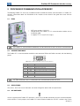
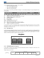
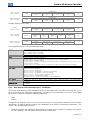
Motors I Automation I Energy I Transmission & Distribution I Coatings Profibus DP SCA06 User’s Manual Profibus DP User’s Manual Series: SCA06 Language: English Document Number: 10001227142 / 00 Publication Date: 12/2012 Contents CONTENTS CONTENTS ...............................................................................................................................3 ABOUT THIS MANUAL............................................................................................................5 ABBREVIATIONS AND DEFINITIONS........................................................................................... 5 NUMERICAL REPRESENTATION ................................................................................................ 5 1 INTRODUCTION TO THE PROFIBUS DP PROTOCOL................................................. 6 1.1 1.2 1.3 1.4 1.5 2 PROFIBUS DP COMMUNICATION ACCESSORY......................................................... 8 2.1 2.2 2.3 2.4 3 ECO3............................................................................................................................... 8 CONNECTOR PINOUT ...................................................................................................... 8 INDICATIONS................................................................................................................... 8 DIP SWITCHES................................................................................................................. 8 INSTALLATION IN THE PROFIBUS DP NETWORK .................................................... 10 3.1 3.2 3.3 3.4 3.5 3.6 3.7 4 PROFIBUS DP NETWORK ................................................................................................. 6 PROFIBUS DP PROTOCOL VERSIONS............................................................................... 6 DEVICE TYPES IN A PROFIBUS DP NETWORK .................................................................. 6 PHYSICAL LAYER ............................................................................................................ 6 APPLICATION PROFILE – PROFIDRIVE.............................................................................. 7 BAUD RATES ................................................................................................................. 10 ADDRESSING................................................................................................................. 10 CABLE........................................................................................................................... 10 CONNECTORS ............................................................................................................... 10 CONNECTION TO THE NETWORK................................................................................... 10 TERMINATING RESISTOR............................................................................................... 11 GSD FILE ....................................................................................................................... 11 PROGRAMMING ..............................................................................................................12 4.1 SYMBOLS FOR THE PROPERTIES DESCRIPTION ............................................................ 12 P0202 – OPERATING MODE...................................................................................................... 12 P0662 – ACTION FOR COMMUNICATION ERROR ...................................................................... 12 P0740 – PROFIBUS DP COMMUNICATION STATUS ................................................................... 13 P0741 – PROFIBUS DATA PROFILE........................................................................................... 13 P0742 – PROFIBUS READING #5............................................................................................... 14 P0743 – PROFIBUS READING #6............................................................................................... 14 P0744 – PROFIBUS READING #7............................................................................................... 14 P0745 – PROFIBUS READING #8............................................................................................... 14 P0746 – PROFIBUS READING #9............................................................................................... 14 P0747 – PROFIBUS READING #10 ............................................................................................. 14 P0748 – PROFIBUS READING #11 ............................................................................................. 14 P0749 – PROFIBUS READING #12 ............................................................................................. 14 P0750 – PROFIBUS READING #13 ............................................................................................. 14 P0751 – PROFIBUS READING #14 ............................................................................................. 14 P0752 – PROFIBUS READING #15 ............................................................................................. 14 P0753 – PROFIBUS READING #16 ............................................................................................. 14 P0754 – PROFIBUS WRITING #5................................................................................................ 15 P0755 – PROFIBUS WRITING #6................................................................................................ 15 P0756 – PROFIBUS WRITING #7................................................................................................ 15 P0757 – PROFIBUS WRITING #8................................................................................................ 15 P0758 – PROFIBUS WRITING #9................................................................................................ 15 P0759 – PROFIBUS WRITING #10.............................................................................................. 15 SCA06 | 3 Contents P0760 – PROFIBUS WRITING #11.............................................................................................. 15 P0761 – PROFIBUS WRITING #12.............................................................................................. 15 P0762 – PROFIBUS WRITING #13.............................................................................................. 15 P0763 – PROFIBUS WRITING #14.............................................................................................. 15 P0764 – PROFIBUS WRITING #15.............................................................................................. 15 P0765 – PROFIBUS WRITING #16.............................................................................................. 15 P0918 – PROFIBUS ADDRESS .................................................................................................. 16 P0922 – SELECTION OF THE CONFIGURATION TELEGRAM....................................................... 16 P0944 – DRIVE FAULT COUNTER.............................................................................................. 17 P0947 – FAULT NUMBER.......................................................................................................... 17 P0963 – PROFIBUS BAUD RATE DETECTION ............................................................................ 18 P0964 – DRIVE IDENTIFICATION ............................................................................................... 18 P0965 – PROFIDRIVE PROFILE IDENTIFICATION ....................................................................... 18 P0967 – PROFIDRIVE CONTROL WORD .................................................................................... 19 P0968 – PROFIDRIVE STATUS WORD ....................................................................................... 19 5 I/O WORDS WITH SPECIFIC FUNCTION ..................................................................... 21 5.1 INPUT WORDS – INPUT (SLAVE –> MASTER) ................................................................... 21 5.1.1 1st – Status Word..................................................................................................... 21 5.1.2 2nd – Motor Speed ................................................................................................... 21 5.1.3 3rd – Torque Current ................................................................................................ 22 5.1.4 4th – Present Control Mode ...................................................................................... 22 5.2 OUTPUT WORDS – OUTPUT (MASTER –> SLAVE) ............................................................ 22 5.2.1 1st – Control Word ................................................................................................... 22 5.2.2 2nd – Speed Reference............................................................................................. 23 5.2.3 3rd – Torque Reference ............................................................................................ 23 5.2.4 4th – Control Mode................................................................................................... 23 6 PROFIBUS DP NETWORK OPERATION ...................................................................... 24 6.1 PROFIBUS DP-V0 ........................................................................................................... 24 6.1.1 Cyclic Data .............................................................................................................. 24 6.1.2 SYNC/FREEZE ......................................................................................................... 24 6.2 PROFIBUS DP-V1 ........................................................................................................... 24 6.2.1 Available Services for Acyclic Communication........................................................... 24 6.2.2 Data Addressing ...................................................................................................... 25 6.2.3 Reading/Writing DP-V1 Telegrams ............................................................................ 25 6.2.4 Data Structure for Parameter Access – PROFIdrive.................................................... 26 6.2.5 Data Structure for Parameter Access – WEG ............................................................. 28 7 FAULTS AND ALARMS RELATED TO THE PROFIBUS DP COMMUNICATION .... 29 A138/F38 – PROFIBUS DP INTERFACE IN CLEAR MODE............................................................ 29 A139/F39 –PROFIBUS DP INTERFACE OFFLINE ........................................................................ 29 A140/F40 – PROFIBUS DP MODULE ACCESS ERROR................................................................ 29 SCA06 | 4 About this Manual ABOUT THIS MANUAL This manual provides the necessary information for the operation of the SCA06 servoconverter using the Profibus DP Interface. This manual must be used together with the SCA06 User’s Guide. ABBREVIATIONS AND DEFINITIONS DP EIA I/O SAP Decentralized Periphery Electronic Industries Alliance Input/Output Service Access Point NUMERICAL REPRESENTATION Decimal numbers are represented by means of digits without suffix. Hexadecimal numbers are represented with the letter ‘h’ after the number. SCA06 | 5 Introduction to the Profibus DP Protocol 1 INTRODUCTION TO THE PROFIBUS DP PROTOCOL A general overview of Profibus DP protocol, describing the main characteristics and functions, are presented next. 1.1 PROFIBUS DP NETWORK The term Profibus is used to describe a digital communication system that can be used in several application areas. It is an open and standardized system, defined by the IEC 61158 and IEC 61784 standards, which comprises from the used physical medium to data profiles for certain sets of equipments. In this system, the DP communication protocol was developed with the purpose of allowing a fast, cyclic and deterministic communication between masters and slaves. Among the several communication technologies that can be used in this system, the Profibus DP technology describes a solution that, typically, is composed by the DP protocol, RS485 transmission medium and application profiles, used mainly in applications and equipments with emphasis in manufacturing automation. Nowadays, there is an organization named Profibus International, responsible for keeping, updating and publishing the Profibus technology among users and members. More information regarding the technology, as well as the complete protocol specification can be obtained with this organization or with one of the regional associations or competence centers associated to the Profibus International (http://www.profibus.com). 1.2 PROFIBUS DP PROTOCOL VERSIONS The Profibus DP protocol defines a series of functions for exchanging data between master and slave. The set of functions can be divided in different functional levels, in the following versions: DP-V0: It is the first version of the protocol, which mainly defines functions to perform cyclic data exchange between master and slave. DP-V1: It is an extension of the functions defined in the first version; it defines particularly how to perform the exchange of acyclic data between master and slave, besides the cyclic data. DP-V2: It defines a set of advanced functions such as communication between slaves and isochronous communication mode. The SCA06 servoconverter supports the services of the DP-V0 and DP-V1 versions. 1.3 DEVICE TYPES IN A PROFIBUS DP NETWORK Three different types of equipment are specified in a Profibus network: Slaves: They are passive stations in the network, which only answer to the requests made by the master. Class 1 Master: It is responsible for the cyclic data exchange. Typically represented by the PLC, or process or plant control software. Class 2 Master: It allows the communication in the Profibus DP network through acyclic messages. Typically represented by an engineering or configuration tool used for network commissioning or maintenance. The SCA06 servoconverter operates as a slave in the Profibus DP network. 1.4 PHYSICAL LAYER There are different network transmission types to allow communication in a Profibus network, each one with suitable features according to the demands of different application types. The main transmission modes are: RS485: this is the most used transmission type for Profibus network. It provides high transmission rates, simple installation and low cost. MBP: this is specified mainly for applications in chemical and petrochemical industries, for communication in safety areas. The transmission rate is defined at 31.25 kbit/s with the possibility of feeding the devices from the communication bus. Optical Fiber: this is used mainly in applications where high electromagnetic interference immunity and/or great distances connections are required. SCA06 | 6 Introduction to the Profibus DP Protocol The Profibus DP accessory of the SCA06 servoconverter provides an RS485 interface for network connection. 1.5 APPLICATION PROFILE – PROFIDRIVE Complementary to the Profibus protocol specification, the PROFIdrive specification, elaborated and kept by the Profibus International, basically describes a set of parameters and services common for the “drive” type equipments in a Profibus network. The purpose of this specification is to facilitate the integration of drives in a Profibus network. The Profibus DP interface for SCA06 servoconverter was developed in accordance with the PROFIdrive specification. Thus, several of the parameters, communication words and data access services of the drive are described in accordance with this specification. SCA06 | 7 Profibus DP Communication Accessory 2 PROFIBUS DP COMMUNICATION ACCESSORY The following Profibus DP accessory is needed in order to enable the device communication in a Profibus DP network. Information about the installation of this module can be found in the guide that came with the accessory. 2.1 ECO3 WEG part number: 11842414. Composed by the Profibus DP-V1 communication module and an installation guide. It supports DP-V1 (acyclic messages). NOTE! The Profibus DP communication module only can be connected to slot 2 of SCA06 servoconverter. 2.2 CONNECTOR PINOUT The Profibus DP-V1 communication module has one connector DB9 to the Profibus network, with the following pinout: Table 2.1: Profibus female DB9 connector pinout (XA112) Pin 1 2 3 4 5 6 7 8 9 Name B-Line (+) RTS GND +5 V A-Line (-) - Function RxD/TxD positive (red) Request To Send 0 V isolated for the RS485 circuit (output) +5 V isolated for the RS485 circuit (output) RxD/TxD negative (green) - NOTE! The DB9 connector frame is connected to the servoconverter protective earth. 2.3 INDICATIONS The alarms, faults and status indications are done through the device HMI and parameters. 2.4 DIP SWITCHES At each segment of the Profibus DP network, it is necessary to enable terminating resistors at both end points of the main bus. For this purpose, the Profibus DP communication module has two DIP switches that can be SCA06 | 8 Profibus DP Communication Accessory activated (both switches to the ON position) to enable the resistor. The DIP switches should not be activated if the network connector already has the terminating resistors. SCA06 | 9 Installation in the Profibus DP Network 3 INSTALLATION IN THE PROFIBUS DP NETWORK The Profibus DP network, such as several industrial communication networks, for being many times applied in aggressive environments with high exposure to electromagnetic interference, requires that certain precautions be taken in order to guarantee a low communication error rate during its operation. Recommendations to perform the product connection in this network are presented next. 3.1 BAUD RATES The Profibus DP protocol defines several baud rates that can be used, from 9.6 kbit/s up to 12Mbit/s. The maximum allowed transmission line length depends on the used baud rate, and this correlation is showed on the table 3.1. Table 3.1: Baud rate x segment length Baud Rate (kbit/s) 9,6; 19,2; 45,45; 93,75 Segment Length (m) 1200 187,5 1000 500 400 1500 3000, 6000, 12000 200 100 All equipments in the network must use the same baud rate. The SCA06 Profibus DP interface has automatic baud rate detection, according to what has been configured for the network master, and therefore it is not necessary to configure this option. It is possible to observe the baud rate detected by the board at the parameter P0963. 3.2 ADDRESSING Every device in a Profibus DP network, master or slave, is identified through a network address. This address must be different for each device. The SCA06 Profibus DP address is configured through the parameter P0918. 3.3 CABLE It is recommended that the installation be carried out with a type A cable, whose characteristics are described in the table 3.2. The cable has a pair of wires that must be shielded and twisted, in order to guarantee higher immunity against electromagnetic interference. Table 3.2: Type A cable properties Impedance Capacitance Loop resistance Cable diameter Wire cross section 3.4 135 a 165 Ω 30 pf/m 110 Ω/km > 0.64 mm > 0.34 mm CONNECTORS Several connector types can be used for the network connection of the equipment, from simple screw connectors up to very specific connector types for the Profibus network. 3.5 CONNECTION TO THE NETWORK The Profibus DP protocol, by using the RS-485 physical medium, allows the connection of up to 32 devices per segment without the use of repeaters. By using repeaters, up to 126 addressable equipments can be connected to the network. Each repeater must also be included as a device connected to the segment, even not occupying a network address. SCA06 | 10 Installation in the Profibus DP Network It is recommended that the connection of all the devices present in the Profibus DP network be made coming from the main bus. Generally, the Profibus network connector itself has an input and an output for the cable, allowing the connection to be taken to the other network points. Derivations from the main bus are not recommended, especially for baud rates higher or equal to 1.5Mbits/s. Figure 3.1: Connection example in a Profibus DP network The Profibus DP network cables must be laid separately (and far away if possible) from the power cables. All the drives must be properly grounded, preferably at the same ground point. The Profibus cable shield must also be grounded. The SCA06 Profibus board connector itself already has a connection with the protective ground and, therefore, makes the connection of the shield to the ground when the Profibus cable is connected to the drive. However a better connection, implemented by clamps that connect the shield to a ground point, is also recommended. 3.6 TERMINATING RESISTOR At each segment of the Profibus DP network, it is necessary to enable a terminating resistor at the end points of the main bus. The use of specific Profibus network connectors with a switch to enable the resistor is recommended, which must only be enabled (ON position) if the equipment is the first or the last element of the segment. The DIP switches present in the communication module also can be used to enable the termination resistors. It is important to emphasize that in order to be possible to disconnect the element from the network without impairing the bus, it becomes interesting the use of active terminations, which are elements that have only the termination function. Therefore, any drive of the network can be disconnected from the bus without impairing the termination. 3.7 GSD FILE Each element of the Profibus DP network has an associated configuration file with the GSD extension. This file describes the characteristics of each equipment and it is used by the Profibus DP network master configuration tool. During the master configuration the GSD configuration file supplied with the equipment must be used. SCA06 | 11 Programming 4 PROGRAMMING Next, the SCA06 servoconverter parameters related to the Profibus DP communication will be presented. 4.1 SYMBOLS FOR THE PROPERTIES DESCRIPTION RO CFG DP Read-only parameter Parameter that can be changed only with a stopped motor Parameter visible on the HMI if the product has the Profibus interface installed P0202 – OPERATING MODE Value Range: Properties: Default: 2 1 = Torque Mode 2 = Speed Mode 3 = Reserved 4 = Ladder Mode 5 = CANopen 6 = Profibus DP CFG Description: This parameter defines the operating mode of the SCA06 servoconverter. In order to control de equipment via Profibus DP network, it’s necessary to use mode 6 = Profibus DP. In cases this mode is programmed, commands and references for the product operation will be provided by cyclic data via Profibus DP network. NOTE! The control of the equipment through the objects for drives is only possible for operating mode 6, but the Profibus DP communication can be used in any operating mode. The Profibus DP interface allows speed and torque control of the SCA06 servoconverter. To perform positioning functions, the Ladder operating mode must be used, developing a Ladder application program and using user’s parameters as the interface with the network master to control and monitor the equipment. P0662 – ACTION FOR COMMUNICATION ERROR Range: Properties: 0 = Cause Alarm 1 = Cause Fault 2 = Cause alarm and execute STOP 3 = Cause alarm and disable drive CFG Default: 0 Description: This parameter allows selecting which action must be executed by the equipment in case it is controlled via network and a communication error is detected. Table 4.1: Options for the parameter P0662 Option 0 = Cause Alarm 1 = Cause Fault 2 = Execute STOP 3 = Disable drive Description It just indicates alarm. Instead of alarm, a communication error causes a fault on the equipment, and it is necessary to reset the faults so as to return to normal operation. The alarm will be indicated together with the execution of the STOP command. It is necessary to reset the faults or disable the drive for the servo to exit this condition. The alarm will be indicated together with the execution of the disable command. The followings events are considered communication errors: Serial Communication (RS232/RS485): Alarm A00128/Fault F00028: timeout of the serial interface. SCA06 | 12 Programming Profibus DP communication: Alarm A138/Fault F38: equipment received command to operate in clear mode. Alarm A139/Fault F39: equipment went into offline status. Alarm A140/Fault F40: Profibus interface access error. P0740 – PROFIBUS DP COMMUNICATION STATUS Range: Properties: 0 = Inactive 1 = Profibus interface initialization error 2 = Offline 3 = Configuration data error 4 = Parameterization data error 5 = Clear mode 6 = Online RO Default: - Description: It allows identifying if the Profibus DP interface board is properly installed, besides indicating the status of the communication with the network master. Table 4.2: Parameter P0740 values Value 0 = Inactive 1 = Profibus interface initialization error 2 = Offline 3 = Configuration data error 4 = Parameterization data error 5 = Clear mode 6 = Online Description The Profibus interface is not installed in SCA06. A problem was identified during the Profibus interface initialization. The Profibus interface is installed and properly configured, but no cyclic communication is established. Data received in the I/O configuration telegram are not in accordance with the configurations done through the parameter P0922. Data received in the parameterization telegram does not have valid format/values. During data exchange with the master, the slave received a command to enter the clear mode. I/O data exchange between the slave and Profibus network master is successfully running. P0741 – PROFIBUS DATA PROFILE Range: Properties: Default: 1 0 = PROFIdrive 1 = Manufacturer DP Description: It allows selecting the data profile for the control, speed reference, status and motor speed words during the I/O data exchange with the network master. Table 4.3: Parameter P0741 options Option 0 = PROFIdrive 1 = Manufacturer Description The control, status, speed reference and motor speed words have values and functions according to what is described by the PROFIdrive specification. The description of each word is done in the following parameters: P0967: PROFIdrive control word. P0968: PROFIdrive status word. The speed reference and motor speed words for this profile are described next. The control, status, speed reference and motor speed words have values and functions specific for SCA06 servoconverter. The description of each word is done in the item 5. SCA06 | 13 Programming Speed for PROFIdrive profile: If the used profile is the PROFIdrive, both the speed reference and the motor speed must be indicated as a value proportional to the drive positive speed limit, programmed through P0134: Value via Profibus = 0000h (0 decimal) → Speed = 0 rpm Value via Profibus = 4000h (16384 decimal) → Speed = maximum speed (P0134) Intermediary speed values in rpm can be obtained using this scale. For instance, if P0134 is programmed for 1800 rpm and the motor speed value read via Profibus is 2048 (0800 h), in order to obtain the value in rpm the following calculation must be done: 16384 => 1800 rpm 2048 => speed in rpm Speed in rpm = 1800 × 2048 16384 Speed in rpm = 225 rpm The same calculation applies for the transmission of speed reference values. Negative speed values indicate reverse speed direction. NOTE! The reference writing does also depend on the bit 6 of the PROFIdrive control word (P0967). If this parameter is changed, the slave will assume the new configuration only when there is no cyclic communication with the master. P0742 – PROFIBUS READING #5 P0743 – PROFIBUS READING #6 P0744 – PROFIBUS READING #7 P0745 – PROFIBUS READING #8 P0746 – PROFIBUS READING #9 P0747 – PROFIBUS READING #10 P0748 – PROFIBUS READING #11 P0749 – PROFIBUS READING #12 P0750 – PROFIBUS READING #13 P0751 – PROFIBUS READING #14 P0752 – PROFIBUS READING #15 P0753 – PROFIBUS READING #16 Range: Properties: 0 to 1249 DP Default: 0 (disabled) Description: These parameters allow programming the content of the input words 5 to 16 (input: drive sends to the master). By using these parameters it is possible to program the number of another parameter whose content must be made available at the network master input area. SCA06 | 14 Programming If, for instance, one wants to read from the SCA06 servoconverter the motor current in Amps, one must program the value 3 in one of these parameters, because the parameter P0003 is the one that contains this information. It is worthwhile to remind that the value read from any parameter is represented with a 16 bit word. Even if the parameter has decimal resolution, the value is transmitted without the indication of the decimal places. E.g., if the parameter P0003 has the value 4.7A, the value supplied via the network will be 47. These parameters are used only if the equipment is programmed at the parameter P0922 to use the options 5 to 16 (configuration telegrams 105 to 116). Up to 16 words to be read by the network master can be made available, according to the selected option. The first two input words are fixed and represent the status and the motor speed. The words 3 and 4, when programmed, represent the current and control mode for servomotor. NOTE! The value 0 (zero) disables the reading in the word. The number of input words, however, keeps the same as programmed at P0922. P0754 – PROFIBUS WRITING #5 P0755 – PROFIBUS WRITING #6 P0756 – PROFIBUS WRITING #7 P0757 – PROFIBUS WRITING #8 P0758 – PROFIBUS WRITING #9 P0759 – PROFIBUS WRITING #10 P0760 – PROFIBUS WRITING #11 P0761 – PROFIBUS WRITING #12 P0762 – PROFIBUS WRITING #13 P0763 – PROFIBUS WRITING #14 P0764 – PROFIBUS WRITING #15 P0765 – PROFIBUS WRITING #16 Range: Properties: 0 to 1249 DP Default: 0 (disabled) Description: These parameters allow programming the content of the output words 5 to 16 (output: master sends to the drive). Using these parameters, it is possible to program the number of another parameter whose content must be made available at the network master output area. If, for instance, one wants to write the ramp for STOP function value in the SCA06 servoconverter, one must program the value 105 in one of these parameters, because the parameter P0100 is the one where this information is programmed. It is worthwhile to remind that the value written in any parameter is represented with a 16 bit word. Even if the parameter has decimal resolution, the value is transmitted without the indication of the decimal places. E.g., if one wishes to program any parameter with the value 5.0s, the value programmed via the network must be 50. These parameters are used only if the equipment is programmed at the parameter P0922 to use the options 5 to 16 (configuration telegrams 105 to 116). Up to 16 words to be written by the network master can be made available, according to the selected option. SCA06 | 15 Programming The first two output words are fixed and represent the control and the speed reference. The words 3 and 4, when programmed, represent the current reference and control mode for servomotor. NOTE! The value 0 (zero) disables the writing in the word. The number of input words, however, keeps the same as programmed at P0922. The written parameters using these words are not saved in non-volatile memory. Thus, if the equipment is turned off and on again, these parameters will return to their original value. P0918 – PROFIBUS ADDRESS Range: Properties: 1 to 126 DP Default: 1 Description: It allows programming the slave address in the Profibus DP network. It is necessary that each of the equipments in the network has an address different from the others. NOTE! If this parameter is changed, the slave will assume the new configuration only when there is no cyclic communication with the master. P0922 – SELECTION OF THE CONFIGURATION TELEGRAM Range: Valores: Properties: 2 = Standard Telegram 1 (2 I/O words) 3 = Telegram 103 (3 I/O words) 4 = Telegram 104 (4 I/O words) 5 = Telegram 105 (5 I/O words) 6 = Telegram 106 (6 I/O words) 7 = Telegram 107 (7 I/O words) 8 = Telegram 108 (8 I/O words) 9 = Telegram 109 (9 I/O words) 10 = Telegram 110 (10 I/O words) 11 = Telegram 111 (11 I/O words) 12 = Telegram 112 (12 I/O words) 13 = Telegram 113 (13 I/O words) 14 = Telegram 114 (14 I/O words) 15 = Telegram 115 (15 I/O words) 16 = Telegram 116 (16 I/O words) DP Default: 2 Description: It allows selecting which configuration telegram is used by the drive during the Profibus DP network initialization. This telegram defines the format and quantity of input/output data exchanged with the network master. During the network master configuration, by using the GSD file, it is possible to select the desired data module for the exchange of cyclic data between the master and the slave. It is possible to exchange from 2 to 16 input/output (I/O) words (16 bits each), depending on the selected option. The value programmed in this parameter must coincide with the module selected by the network master configuration tool. The content of the first two input/output words is pre-defined. The other words are programmable through the parameters P0742 up to P0765: SCA06 | 16 7I/O ... 16I/O 6I/O 5I/O 4I/O #1 #2 #3 #4 #5 #6 #7 #8 #9 #10 #11 #12 #13 #14 #15 #16 Output (master → slave) Control Word Speed Reference Torque Reference Control Mode Writing Profibus #5 Writing Profibus #6 Writing Profibus #7 Writing Profibus #8 Writing Profibus #9 Writing Profibus #10 Writing Profibus #11 Writing Profibus #12 Writing Profibus #13 Writing Profibus #14 Writing Profibus #15 Writing Profibus #16 3I/O Word 2I/O Input (slave → master) Status Word Motor Speed Torque Current Control Mode Feedback Reading Profibus #5 Reading Profibus #6 Reading Profibus #7 Reading Profibus #8 Reading Profibus #9 Reading Profibus #10 Reading Profibus #11 Reading Profibus #12 Reading Profibus #13 Reading Profibus #14 Reading Profibus #15 Reading Profibus #16 15I/O Programmable Fixed Programming NOTE! The format of the control, status, speed reference and motor speed words depends on the parameter P0741 programming. If this parameter is changed, the slave will assume the new configuration only when there is no cyclic communication with the master. P0944 – DRIVE FAULT COUNTER Range: Properties: 0 to 1 RO, DP Default: - Description: It is a Profibus DP communication specific parameter, defined by the PROFIdrive standard, to indicate the number of faults occurred in the drive. If any fault indication occurs at the equipment, this counter will be incremented. For the SCA06 servoconverter only one fault at a time is registered, thus, this counter has a maximum value of 1. The value 0 (zero) indicates that the drive is not in fault status. The parameter content is reset together with the drive reset. P0947 – FAULT NUMBER Range: Properties: 0 to 65535 RO, DP Default: - Description: It is a Profibus DP communication specific parameter, defined by the PROFIdrive standard, to indicate the fault occurred in the SCA06 servoconverter. If any fault occurs in the equipment, this parameter will have the code of the occurred fault. The value 0 (zero) indicates that the drive is not in fault status. SCA06 | 17 Programming P0963 – PROFIBUS BAUD RATE DETECTION Range: Properties: 0 = 9.6 kbit/s 1 = 19.2 kbit/s 2 = 93.75kbit/s 3 =187.5 kbit/s 4 = 500 kbit/s 5 = Não detectada 6 = 1500 kbit/s 7 = 3000 kbit/s 8 = 6000 kbit/s 9 = 12000 kbit/s 10 = Reservado 11 = 45.45 kbit/s RO, DP Default: - Description: It is a Profibus DP communication specific parameter, defined by the PROFIdrive standard, to indicate the baud rate detected by the Profibus DP interface. P0964 – DRIVE IDENTIFICATION Range: Properties: 0 to 65535 RO, DP Default: - Description: It is a Profibus DP communication specific parameter, defined by the PROFIdrive standard, to indicate information about the drive. This parameter has 5 sub-indices with information on the drive, but the sub-indices 1 to 4 are accessible only using the acyclic access to parameters defined by the PROFIdrive profile. Other interfaces access only the sub-index 0. Sub-index 0: Sub-index 1: Sub-index 2: Sub-index 3: Sub-index 4: Manufacturer = 367 Drive Unit Type = 4 Version (software) = Equipment firmware version (P0023) Firmware Date (year) = Firmware elaboration year, in yyyy format. Firmware Date (day/month)) = Firmware elaboration day and month, in ddmm format. P0965 – PROFIDRIVE PROFILE IDENTIFICATION Range: Properties: 0 to 65535 RO, DP Default: - Description: It is a Profibus DP communication specific parameter, defined by the PROFIdrive standard, to indicate the profile and profile version used by the drive. For the SCA06 servoconverter, this parameter has a fixed value that can be divided in two bytes (high portion and low portion of the 16 bit word), where each byte has the following value: Byte 1 (high byte): profile number = 3 (PROFIdrive) Byte 2 (low byte): profile version = 41 (PROFIdrive Profile Version 4.1) The value showed in the parameter is 809, which represents the decimal value concatenating the two bytes. SCA06 | 18 Programming P0967 – PROFIDRIVE CONTROL WORD Range: Properties: Default: 0000h 0000h to FFFFh DP Description: It is a Profibus DP communication specific parameter, defined by the PROFIdrive standard, with the inverter control word via the Profibus DP interface when the PROFIdrive data profile is selected at P0741. This parameter can only be changed via Profibus DP interface. For the other sources (HMI, CAN, etc.) it behaves like a read-only parameter. In order that the commands written in this parameter be executed, it is necessary to program the drive to be commanded via Profibus DP on parameter P0202. 7 6 5 4 3 2 Fault Acknowledge Enable Setpoint Reserved Enable Ramp Generator Enable Operation No Quick Stop 1 0 ON 8 No Coast Stop 9 JOG 1 ON Function 10 Reserved 15 – 11 Control By PLC Bits Reserved The specific functions in this word follow the defined by the PROFIdrive specification. Each bit of this word corresponds to a command that can be executed by the drive: Table 4.4: Parameter P0967 bit functions Bits Bit 0 ON / OFF Bit 1 No Coast Stop / Coast Stop Bit 2 No Quick Stop / Quick Stop Bit 3 Enable Operation Bit 4 Enable Ramp Generator Bit 5 Bit 6 Enable Setpoint Bit 7 Fault Acknowledge Bit 8 JOG 1 ON Bit 9 Bit 10 Control By PLC Bits 11 to 15 Values 0: OFF -> If enabled, it stops and disables the drive. 1: ON -> It allows the inverter enabling. 0: Coast Stop -> It disables the drive. 1: No coast Stop -> It allows the drive enabling. 0: If enabled, it executes the Fast Stop command and disables the drive. 1: It allows the inverter drive. 0: It disables the drive. 1: It enables the drive. Not used for SCA06. Reserved 0: It resets the speed reference. 1: It uses the speed reference received via the Profibus DP network. 0: No function. 0->1: If in a fault condition, it executes the fault reset. Not used for SCA06. Reserved Reserved. NOTE! The speed direction reversion can be done by sending a negative value to the speed reference. P0968 – PROFIDRIVE STATUS WORD Range: Properties: 0000h to FFFFh RO, DP Default: - Description: It is a Profibus DP communication specific parameter, defined by the PROFIdrive standard, with the drive status word via the Profibus DP interface when the PROFIdrive data profile is selected at P0741. SCA06 | 19 Programming 6 5 4 3 2 Switching On Inhibited Quick Stop Not Active Coast Stop Not Active Fault Present Operation Enabled 1 0 Ready To Swtich On 7 Ready To Operate 8 Warning Present Function 9 Reserved 15 – 10 Control Requested Bits Reserved The specific functions in this word follow the defined by the PROFIdrive specification. Each bit of this word corresponds to one state: Table 4.5: Parameter P0968 bit functions Bits Bit 0 Ready To Swtich On Bit 1 Ready To Operate Bit 2 Operation Enabled Bit 3 Fault Present Bit 4 Coast Stop Not Active Bit 5 Quick Stop Not Active Bit 6 Switching On Inhibited Bit 7 Warning Present Bit 8 Bit 9 Control Requested Bits 10 to 15 Values 0: The drive cannot be enabled. 1: Drive can be enabled (no safety stop). 0: No commands received from the master to operate the equipment. 1: Commands received from the master allow enabling the drive (power is on). 0: The drive is disabled. 1: Drive enabled, and able to receive the command to release the ramp. 0: The drive is not in a fault condition. 1: The drive is in a fault condition. 0: The drive is disabled. 1: The drive is enabled. 0: The drive is with a Fast Stop command active. 1: Fast Stop command is not active at the drive (STOP function). Not used for SCA06. 0: No alarm. 1: The drive has an active alarm. Reserved. 0: The drive is operating in local mode. 1: Drive control is via Profibus DP interface. Reserved. SCA06 | 20 I/O Words With Specific Function 5 I/O WORDS WITH SPECIFIC FUNCTION The servoconverter SCA06 can communicate from 2 to 16 input/output words (I/O) and this quantity can be programmed through parameter P0922. The first four I/O words have pre-defined functions, whose formats and functions are described below. 5.1 INPUT WORDS – INPUT (SLAVE –> MASTER) 5.1.1 1st – Status Word Word that indicates the equipment status, providing information about licenses, faults, etc. The format of this word depends on the type of data profile programmed in P0741: 6 5 4 3 2 Energized Power In Fault Enabled 1–0 Reserved 7 In Stop Function 13 – 8 Safety function active 14 In Alarm 15 Reserved Bits Limit switch clockwise active P0741 = 0 (PROFIdrive): status word described by the PROFIdrive specification, as per P0968. P0741 = 1 (Manufacturer): specific status word of the SCA06, as described below. Limit switch counterclockwise active Table 5.1: Functions of the bits for the specific status word of the SCA06 Bits Bits 0 and 1 Bit 2 Enabled Bit 3 In Fault Bit 4 Power Energized Bit 5 In Stop Bit 6 Safety Stop Active Bit 7 In Alarm Bits 8 to 13 Bit 14 Limit switch clockwise active Bit 15 Limit switch counterclockwise active 5.1.2 Description Reserved 0: Drive disabled. 1: Drive enabled, it is driving the motor according to the control mode. 0: No fault in the drive. 1: Drive in fault status. 0: No power on the power circuit or in undervoltage. 1: Power circuit of the drive fully energized, ready to enable.lui 0: STOP function inactive. 1: STOP function active. 0: Safety stop function (STO) inactive. 1: Safety stop function (STO) inactive. 0: No alarm. 1: Drive with some active alarm. Reserved 0: No limit switch clockwise signal. 1: Limit switch clockwise signal was activated. 0: No limit switch counterclockwise signal. 1: Limit switch counterclockwise signal was activated. 2nd – Motor Speed Word that indicates the motor speed. The speed scale depends on the type of data profile programmed in P0741: P0741 = 0 (PROFIdrive): speed proportional to maximum speed, as described in P0741. P0741 = 1 (Manufacturer): specific motor speed of the SCA06, where the value 7FFFh (32767) corresponds to 18750 rpm. Negatives values represent the motor spinning counterclockwise. NOTE! In this word, it is indicated the instant speed value, without filter. For this reason, it is normal the oscillation of the value read around the operation point. SCA06 | 21 I/O Words With Specific Function 5.1.3 3rd – Torque Current Word that indicates the torque current, proportional to the equipment current that generates torque. The indication is done in ampere (A), with one-decimal place resolution. Example: If the current value is 4.7A, the value read via network will be 47. 5.1.4 4th – Present Control Mode It indicates which control mode is selected for the equipment: 3–0 Control Mode 15 – 4 Reserved Bits Function Table 5.2: Functions of the bits for the control mode of the SCA06 Bits Values It defines present control mode of the equipment: 0 = Torque mode 1 = Speed mode 3 = Position mode Reserved Bits 3 – 0 Control Mode Bits 15 – 4 5.2 OUTPUT WORDS – OUTPUT (MASTER –> SLAVE) 5.2.1 1st – Control Word Word that allows sending command to the equipment. Only used by the SCA06 if the operating mode is set for Profibus DP (P0202 = 6). The format of this word depends on the type of data profile programmed in P0741: 3 2 1–0 Reserved 6–4 Activate STOP 7 Enable Function 15 – 8 Reserved Bits Fault Reset P0741 = 0 (PROFIdrive): control word described by the PROFIdrive specification, as per P0967. P0741 = 1 (Manufacturer): specific control word of the SCA06 as described below. Reserved Table 5.3: Functions of the bits for specific control word of the SCA06 Bits Bits 1 and 0 Bit 2 Activate STOP Bit 3 Enable Bits 6 – 4 Bit 7 Fault Reset Bits 15 – 8 Values Reserved 0: No STOP function. 1: Activates STOP function. 0: Disable drive. 1: Enable Drive. Reserved 0: No function. 0 –> 1: Resets the equipment faults. Reserved SCA06 | 22 I/O Words With Specific Function 5.2.2 2nd – Speed Reference Word for programming the motor speed reference. The reference scale depends on the type of data profile programmed in P0741: P0741 = 0 (PROFIdrive): speed proportional to maximum speed, as described in P0741. P0741 = 1 (Manufacturer): specific motor speed of the SCA06, where the value 7FFFh (32767) corresponds to 18750 rpm. Negatives values represent the motor spinning counterclockwise. 5.2.3 3rd – Torque Reference Word that allows programming the reference for the torque current of the servoconverter. The reference is programmed in ampere (A), with one-decimal place resolution. Example: when sending the value 47, the drive will take a reference equal to 4.7A. 5.2.4 4th – Control Mode Function 15 – 4 3–0 Control Mode Bits Reserved Allows programming the equipment control mode: Table 5.4: Functions of the bits for the control mode of the SCA06 Bits Bits 3 – 0 Control mode Bits 15 – 4 Values It defines the present control mode of the equipment: 0 = Torque mode 1 = Speed mode Other values are reserved. Reserved NOTE! The Profibus DP interface allows speed and torque control of the servoconverter SCA06. To perform positioning functions, the Ladder operating mode must be used, developing a Ladder application program and using the user’s parameter as interface with the network master to control and monitor the equipment. For the option P0922 = 2, the control mode will be programmed for speed, while for P0922 = 3, the control mode will be programmed for torque. For the other options, the control mode will depend on the value programmed in this word. SCA06 | 23 Profibus DP Network Operation 6 PROFIBUS DP NETWORK OPERATION The SCA06 servoconverter with Profibus DP communication accessory operates as a slave in the network and supports the network services of DP-V0 and DP-V1 communication protocols. Information about the inverter operation using the services specified on these versions is presented below. 6.1 PROFIBUS DP-V0 6.1.1 Cyclic Data The communication via cyclic data allows the data transfer in two directions: Input data: Data transmitted from the slave to the master, for monitoring the status and the variables of each slave. Output data: Data transmitted from the master to the slave, for control and transmission of operation data to the equipment. These data are transmitted in regular time periods, defined by the baud rate, number of slaves in the network and the amount of data exchanged with each slave. The number of input/output (I/O) words available for the SCA06 depends on the format of the configuration telegram, programmed through the parameter P0922. It is possible to communicate from 2 to 10 input words and the same number of output words. The contents of these words depend on the setting of the parameters P0741 to P0757. The same programming done at the parameter P0922 must also be configured at the network master, using a master configuration tool and the SCA06 GSD file, selecting one of the available modules described in the GSD file. 6.1.2 SYNC/FREEZE The SCA06 servoconverter supports the SYNC/UNSYNC and FREEZE/UNFREEZE commands. These are global commands that the master can send to all the network slaves, allowing simultaneous update of I/O data in the network equipments. The SYNC/UNSYNC commands act on the master output data. When receiving a SYNC command, the command and speed reference values received by each slave are frozen. Values received later by the slave are stored, but will only be updated after the reception of a new SYNC command, or after the UNSYNC command, which cancels this function. The FREEZE/UNFREEZE commands act in a similar form as the SYNC, but their action is associated to the master input data. When receiving a FREEZE command, variable and status values of each slave are frozen. These values remain fixed until a new FREEZE command be received, or after the UNFREEZE command, which cancels this function. 6.2 PROFIBUS DP-V1 In addition to the services defined by the first version of the Profibus DP specification (DP-V0), where it is mainly defined how to perform the exchange of cyclic data for equipment control and monitoring, the SCA06 servoconverter with the Profibus DP communication accessory also supports the DP-V1 additional services for acyclic communication. Using these services, it id possible to read/write drive parameters using DP-V1 acyclic function, both by the network master (class 1 master) and by a commissioning tool (class 2 master). 6.2.1 Available Services for Acyclic Communication The device supports the following services for acyclic communication in the Profibus DP network: Communication between class 1 master and slave (MS1): Data acyclic reading (DS_Read) Data acyclic writing (DS_Write) SCA06 | 24 Profibus DP Network Operation Communication between class 2 master and slave (MS2): Initiates the connection (Initiate) Data acyclic reading (DS_Read) Data acyclic writing (DS_Write) Aborts the connection (Abort) DP-V1 requests use an SD2 type Profibus DP telegram – with variable data length. This type of telegram has the following fields: SD 68h SD LE LEr DA SA FC DSAP SSAP DU FCS ED LE xx LEr Xx Telegram Header SD DA SA 68h xx xx FC xx DSAP xx Data Unit DU xx ... SSAP xx Telegram End FCS ED xx 16h Telegram start delimiter (Start Delimiter) Telegram length, from the DA field to the DU (Length) Telegram length repetition (Length repeat) Destination Address Source Address Function Code Destination Service Access Point Source Service Access Point Data unit, size 1 to 244 (Data Unit for DP services) Telegram checking byte (Frame Checking Sequence) Telegram end delimiter (End Delimiter) In this telegram it matters to describe the data structure in the DU field, where the form to access the drive parameters is defined. The other fields follow the defined by the Profibus specification and, normally, are controlled by the network master. 6.2.2 Data Addressing In the functions for reading and writing via acyclic data, these data are addressed with a numbering indicating which slot and index are being accessed. The slots can be used to address different physical segments of an equipment (a modular equipment for instance) or even logical segments inside a single equipment. The index indicates which data inside the segment is being accessed. ↔ Profibus Network Slave Slot 0 Index 0 Index 1 Index 2 ... Index 254 Slot 1 Index 0 Index 1 Index 2 ... Index 254 ... Slot N Index 0 Index 1 Index 2 ... Index 254 ... Figure 6.1: Acyclic Data Addressing 6.2.3 Reading/Writing DP-V1 Telegrams In the Profibus DP protocol, the writing (DS_Write) and reading (DS_Read) DP-V1 telegrams used to access the parameters have the following structure: Writing Telegram (DS_Write): Data Unit (DU) Request (master -> slave) Header Function 5Fh Slot 0 Index 47 Size n Request Data (n bytes) End SCA06 | 25 Profibus DP Network Operation Data Unit (DU) Positive response (slave -> master) Header Function 5Fh Slot 0 Negative Response (slave -> master) Header Function DFh Error Decode 128 Function 5Eh Slot 0 Index 47 Size 0 End Error Code 1 xx Error Code 2 xx End Size 240 End Data Unit (DU) Reading Telegram (DS_Read): Request (master -> slave) Header Data Unit (DU) Index 47 Data Unit (DU) Positive response (slave -> master) Header Negative Response (slave -> master) Header Function 5Eh Slot 0 Index 47 Size n Response Data (n bytes) Data Unit (DU) Function DEh Error Decode 128 Error Code 1 xx Error Code 2 xx End End Each telegram field can assume the following values: Function Slot Index Size Error Decode Error Code 1 Error Code 2 Request Data Response Data 6.2.4 5Fh – Writing request, positive response for writing 5Eh – Reading request, positive response for reading DFh – Negative response for writing DEh – Negative response for reading 0 (It is the standard slot for accessing the drive parameters, according to PROFIdrive) 47 (It is the standard index for accessing the drive parameters, according to PROFIdrive) Number of bytes for reading and writing. Writing request: ‘n’ bytes, according to the number of bytes in the request telegram. Positive response for writing: 0 bytes Reading request: 240 bytes (It requests the maximum number of reading bytes, because the size of the slave response is variable). Positive response for reading: ‘n’ bytes, according to the number of bytes in the response telegram. 128 Error code, according to the problem found in the request: B0h: access error – invalid slot B2h: access error – invalid index B5h: access error – modification not allowed for the parameter B6h: access error – modification in read-only parameter B7h: access error – incorrect values for parameter access B8h: access error – invalid parameter number C3h: Resource error – Response not available for the reading request 0 Variable size field of the writing request (DS_Write), which contains the data for accessing the drive parameters. Variable size field of the reading response (DS_Read), which contains the result of the access to the drive parameters. Data Structure for Parameter Access – PROFIdrive The SCA06 servoconverter makes available the access to the inverter entire parameter list through the acyclic data, according to the PROFIdrive specification. According to the specification, the access to the global parameters is achieved through the following addressing: Slot 0 Index 47 Through this slot and index, one must use the structure to access the parameters defined in the PROFIdrive specification, in order to perform readings and modifications of the SCA06 servoconverter parameters. This access uses the following mechanism: 1. Either the reading or the modification of parameters must begin with a writing DP-V1 telegram (DS_Write) at the slot 0 index 47, with the request of the parameter to the drive. SCA06 | 26 Profibus DP Network Operation 2. When receiving the telegram, the SCA06 will test the data consistency in order to know if the request is valid. If errors in the request format are not found, it will respond positively to the request telegram and initiate the data treatment. 3. After receiving writing telegram positive response, reading DP-V1 telegrams (DS_Read) must be sent in order to obtain the response to the request performed previously. If the request has not been processed yet, the drive will respond a reading error. This reading must be repeated until the drive responds with valid data. The fields with the request and response data contain the structure where the parameters accessed at the drive are defined. In this access, as defined by the PROFIdrive, the request and response data have the following structure: Table 6.1: Request data structure Request data header Request Reference DO-ID Attribute Parameter Number Sub-index Repeated 'n' times, according to the number of accessed parameters ... Parameter Address Request ID Nr. of Parameters (n) Nr. of Elements Format Value 1 Value 2... Number of Values Repeated 'n' times, according to the number of accessed parameters ... Parameter value (only for parameter modification requests) Request Reference Request ID DO-ID Nr. of Parameters Attribute Nr. of Elements Parameter Number Sub-index Format Number of Values Value A number between 1 and 255 that will be retransmitted in the response telegram. It represents the type of request made to the slave: 1 = Parameter reading 2 = Parameter modification 0 The number of parameters accessed in the request. 10h (request of the parameter value) For parameters of the array type, it represents the number of elements accessed in the parameter. For the SCA06 only a few parameters specified by the PROFIdrive specification have this format, the other parameters are always formed by a single value, and therefore this field must be set in 0 or 1. The number of a drive valid parameter (the most significant byte is transmitted first). For parameters of the array type, it represents the array element starting from which the access will be made (the most significant byte is transmitted first). For parameters formed by a single item, this field must be set in 0. It defines the format for the writing parameter. For the SCA06 parameters the value 42h (16 bit word) must be used. The number of values to be written (defined in the number of elements). Value to write in the parameter (the most significant byte is transmitted first). Table 6.2: Response data structure Parameter value (only for parameter reading responses, or in case of error) Request Reference Mirror DO-ID Mirror Format Value 1 or error code Value 2 or error code... Response ID Nr. of Parameters (n) Number of Values Repeated 'n' times, according to the number of accessed parameters ... Response data header SCA06 | 27 Profibus DP Network Operation Request Reference mirror Response ID DO-Id Mirror Nr. of Parameters (n) Format Number of values Value Error code 6.2.5 A mirror of the value received in the request telegram. It represents the type of response sent by the slave: 1 = Successful parameter reading 2 = Successful parameter modification 129 = Parameter reading with error 130 = Parameter modification with error Mirror of the value received in the request telegram. The number of parameters accessed in the request. It defines the format of the accessed parameter: 42h = 16 bit word 44h = Parameter access error The number of values read from the parameter, or the number of error codes from the parameter access. Value read from the parameter (the most significant byte is transmitted first). In case of parameter illegal access (error in reading or writing of any of the parameters), the code of the type of found error will be indicated: 0000h = parameter does not exist 0001h = modification of read-only parameter 0002h = parameter value out of the limits 0003h = indicated sub-index does not exist 0004h = parameter not of the array type 0005h = incorrect format for the parameter 0009h = description not available (only value) 000Fh = text not available (only value) 0016h = incorrect access to the parameter 0017h = unknown format 0018h = incorrect number of values Data Structure for Parameter Access – WEG Besides the structure for the access to the parameters according to the PROFIdrive specification, it is also possible to use a simplified structure for the access to the parameters through the following addressing: Slot 0 Index 48. With the telegrams described in the section 6.2.3, it is possible to get access to the parameters using the following mechanism: Parameter modification: the modification of parameters is performed with a writing telegram (DS_Write), with 4 data bytes, were the two first represent the parameter number and the two last represent the parameter content, always with the most significant byte transmitted first. The response to the writing telegram indicates whether or not the modification was successful. Parameter reading: for the reading of parameters, first a writing telegram (DS_Write) with 2 data bytes representing the parameter number must be sent. After this telegram has been successfully sent, a reading telegram (DS_Read) must be sent, and the response will have 2 data bytes with the parameter content. The reading telegrams as well as the writing telegrams are able to report errors in the parameter requests, according to the codes described for the Error Code 1 field. SCA06 | 28 Faults and Alarms Related to the Profibus DP Communication 7 FAULTS AND ALARMS RELATED TO THE PROFIBUS DP COMMUNICATION A138/F38 – PROFIBUS DP INTERFACE IN CLEAR MODE Description: It indicates that the slave has received from the network master the command to enter the Clear mode. Actuation: The indication occurs if, during the cyclic communication, the Profibus DP network master sends to the network a global telegram telling the slaves that they must leave the operation mode and enter the Clear mode. The conditions for the transmission of this command depend on the network master, but it normally indicates a special operation condition, such as during the programming of the master. The message of alarm A138 or fault F38 will in this case be signalized through the HMI, depending on the P0662 programming. In case of alarm, the indication will automatically disappear if a new telegram to leave this mode is received. Possible Causes/Correction: Verify the network master status, making sure it is in execution (RUN) mode. A139/F39 –PROFIBUS DP INTERFACE OFFLINE Description: It indicates an interruption in the communication between the Profibus DP network master and the drive. The Profibus communication interface changed to the offline state. Actuation: It acts when for any reason an interruption in the communication between the drive and the Profibus DP network master occurs after the cyclic communication has been initiated. The time programmed for this detection is received through the parameterization telegram sent by the master. The message of alarm A139 or fault F39 will in this case be signalized through the HMI, depending on the P0662 programming. In case of alarm, the indication will automatically disappear at the moment when the cyclic communication is reestablished. NOTE! When energizing the equipment, the Profibus DP interface will be initialized in the offline state. The error indication, however, will be done only if a transition from online to offline occurs. Possible Causes/Correction: Verify whether the network master is configured correctly and operating normally. Search for short-circuit or bad contact in the communication cables. Make sure the cables are not changed or inverted. Verify whether termination resistors with correct values were installed only at the extremes of the main bus. Verify the entire network installation – cable passage, grounding. A140/F40 – PROFIBUS DP MODULE ACCESS ERROR Description: It indicates error in the access to the Profibus communication module data. Actuation: It acts when the SCA06 control board is not able to read information from the Profibus DP communication module. SCA06 | 29 Faults and Alarms Related to the Profibus DP Communication The message of alarm A140 or fault F40 will in this case be signalized through the HMI, depending on the P0662 programming. It is necessary to cycle the power of the drive so that a new attempt to access the Profibus DP module is done. Possible Causes/Correction: Verify whether the Profibus DP module is fitted properly in the slot 3. Hardware errors caused by the improper handling or installation of the accessory can cause this error. If possible, test it by replacing the communication accessory. SCA06 | 30 WEG Equipamentos Elétricos S.A. Jaraguá do Sul – SC – Brasil Fone 55 (47) 3276-4000 – Fax 55 (47) 3276-4020 São Paulo – SP – Brasil Fone 55 (11) 5053-2300 – Fax 55 (11) 5052-4212 [email protected] www.weg.net