1
Motors I Automation I Energy I Transmission & Distribution I Coatings
WEGTP
SCA06
User’s Manual
WEGTP User’s Manual
Series: SCA06
Language: English
Document Number: 10001626001 / 00
Publication Date: 12/2012
Contents
CONTENTS
CONTENTS .........................................................................................................................3 ABOUT THIS MANUAL ......................................................................................................4 ABBREVIATIONS AND DEFINITIONS......................................................................................................... 4 NUMERICAL REPRESENTATION ............................................................................................................... 4 1 INTRODUCTION TO SERIAL COMMUNICATION ......................................................5 2 DESCRIPTION OF THE INTERFACES ........................................................................6 2.1 RS232 AND RS485 ECO1 COMMUNICATION AND EXPANSION MODULE ............................... 6 2.2 RS232 ................................................................................................................................................. 6 2.2.1 Indications .................................................................................................................................. 6 2.2.2 Connection to Network RS232 ................................................................................................. 6 2.2.3 Connecting cables in RS232..................................................................................................... 6 2.2.4 Connector Pin Assignment ....................................................................................................... 6 2.3 RS485 ................................................................................................................................................. 7 2.3.1 Indications .................................................................................................................................. 7 2.3.2 Characteristics of the RS485 interface.................................................................................... 7 2.3.3 Connector Pin Assignment ....................................................................................................... 7 2.3.4 Termination resistor .................................................................................................................. 8 2.3.5 Connection to RS485 network.................................................................................................. 8 3 PROGRAMMING ..........................................................................................................9 3.1 SYMBOLS FOR THE PROPERTIES DESCRIPTION........................................................................ 9 P00650 – SERVO DRIVE ADDRESS IN THE SERIAL COMMUNICATION 1 – RS232.............................. 9 P00656 – SERVO DRIVE ADDRESS IN THE SERIAL COMMUNICATION 2 – RS485............................. 9 P00652 – BIT RATE SERIAL 1 – RS232....................................................................................................... 9 P00658 – BIT RATE SERIAL 2 – RS485....................................................................................................... 9 P00653 – SERIAL CONFIGURATION 1 – RS232 ...................................................................................... 10 P00659 – SERIAL CONFIGURATION 2 – RS485 ...................................................................................... 10 P00654 – SELECT SERIAL PROTOCOL 1 – RS232.................................................................................. 10 P00660 – SELECT SERIAL PROTOCOL 2 – RS485.................................................................................. 10 P0662 – ACTION FOR COMMUNICATION ERROR ................................................................................. 10 P00663 – WATCHDOG SERIAL ................................................................................................................. 11 P00664 – SAVE PARAMETERS IN NON-VOLATILE MEMORY.............................................................. 11 P00667 – SAVE ON MARKERS.................................................................................................................. 11 4 WEGTP PROTOCOL ..................................................................................................13 4.1 ADDRESSING IN WEGTP PROTOCOL .......................................................................................... 13 4.2 PROTOCOL FIELDS ........................................................................................................................ 13 4.3 TELEGRAM FORMAT...................................................................................................................... 14 4.3.1 Reading telegram..................................................................................................................... 14 4.3.2 Writing telegram....................................................................................................................... 15 4.4 EXAMPLE OF TELEGRAMS USING THE WEGTP PROTOCOL ................................................... 15 5 FAULTS AND ALARMS RELATED TO WEGTP COMMUNICATION .......................17 A00128/F00028 – TIMEOUT AT THE TELEGRAM RECEPTION ............................................................. 17 I. APPENDICES .............................................................................................................18 APPENDIX A. ASCII TABLE .................................................................................................................... 18
SCA06 | 3
About this Manual
ABOUT THIS MANUAL
This manual supplies the necessary information for the operation of the SCA06 servodrive using the RS232 and
RS485 serial interfaces. This manual must be used together with the SCA06 user manual.
ABBREVIATIONS AND DEFINITIONS
ASCII
CRC
EIA
TIA
RTU
American Standard Code for Information Interchange
Cycling Redundancy Check
Electronic Industries Alliance
Telecommunications Industry Association
Remote Terminal Unit
NUMERICAL REPRESENTATION
Decimal numbers are represented by means of digits without suffix. Hexadecimal numbers are represented with
the letter ‘h’ after the number.
SCA06 | 4
Introduction to Serial Communication
1 INTRODUCTION TO SERIAL COMMUNICATION
In a serial interface the data bits are sent sequentially through a communication channel or bus. Several
technologies use the serial communication for data transfer, including the RS232 and RS485 interfaces.
The directions that specify the RS232 and RS485 standards, however, do neither specify the character format,
nor its sequence for the data transmission and reception. Therefore, besides the interface, it is also necessary to
identify the protocol used for the communication. Among the several existent protocols, one used a lot in the
industry is the WEGTP protocol.
In the sequence the characteristics of the RS232 and RS485 serial interfaces available for the product will be
presented, as well as the protocols for the use of those interfaces.
SCA06 | 5
Description of the Interfaces
2 DESCRIPTION OF THE INTERFACES
To enable the serial communication on the servodrive SCA06, you must use the communication and expansion
module ECO1 described below. Information about the installation of this module can be found in the guide that
comes with the accessory.
2.1
RS232 AND RS485 ECO1 COMMUNICATION AND EXPANSION MODULE
2.2
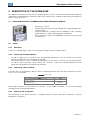
WEG Item: 11330271.
Composed by the communication module ECO1 (figure beside) and a
mounting guide.
Interface galvanically insulated and with differential signal, providing
greater robustness against electromagnetic interference.
RS232 and RS485 signals are independent channels and can be used
simultaneously.
RS232
2.2.1
Indications
O led LA121 indicates (lights) when transmitting data through the communication RS232.
2.2.2
Connection to Network RS232
RX and TX signals of the servo drive must be connected respectively to the TX and RX of the master,
besides the connection of the reference signal (GND).
The interface RS232 is very susceptible to interference. For this reason, the wire used for communication
must be as short as possible – always shorter than 10 meters – and must be routed separately from the
power wiring that feeds the servo drive and the motor.
2.2.3
Connecting cables in RS232
If desired, items of the following cables for RS232 connection between the servo drive and network master,
such as a PC, are available.
Table 2.1: RS232 Cable
Cable
RS232 shielded cable with DB9 connectors
Length: 3 meters
RS232 shielded cable with DB9 female connectors
Length: 10 meters
Item
10050328
10191117
Other cables, however, can be found on the market – usually called null-modem – or can be assembled
according to the installation requirements.
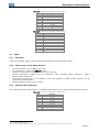
2.2.4
Connector Pin Assignment
The connection for the RS232 interface is available through the XA121 and XA122 connectors using the
following pin assignment:
SCA06 | 6
Description of the Interfaces
Table 2.2: Connector pin assignment for RS232 XA121
Pin
1
2
3
4
5
6
7
8
9
Function
Ground
RX_232
TX_232
Reserved 1
GND
Reserved1
232 RTS
A
B
Table 2.3: Connector pin assignment for RS232 XA122
Pin
1
2
3
4
5
6
7
8
9
Frame
2.3
Function
NC
RX_232
TX_232
Reserved1
GND
NC
232 RTS
NC
NC
Ground
RS485
2.3.1
Indications
O led LA122 indicates (lights) when transmitting data through the communication RS485.
2.3.2
Characteristics of the RS485 interface
The Interface follows the standard EIA/TIA-485.
It can operate as a slave of the WEGTP network.
It allows communication using rates from 9600 to 57600 kbit/s.
Interface galvanically insulated and with differential signal, providing greater robustness against
electromagnetic interference.
It allows the connection of up to 32 devices to the same segment. A larger number of devices can be
connected through repeaters. 2
Maximum length of the bus of 1000 meters.
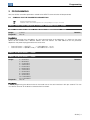
2.3.3
Connector Pin Assignment
The connection for the RS485 interface is available through connector XC1 using the following pin assignment:
Table 2.4: Connector pin assignment for RS485 XA121
Pin
1
2
3
4
5
6
7
8
9
1
2
Function
Ground
RX_232
TX_232
Reserved1
GND
Reserved1
232 RTS
A
B
Do not connect reserved pins.
The maximum number of devices that can be connected to the network also depends on the used protocol.
SCA06 | 7
Description of the Interfaces
Table 2.5: Connector pin assignment for RS485 XA123
Pin
1
2
3
4
5
6
7
8
9
Frame
2.3.4
Function
NC
NC
NC
NC
GND
Reserved
NC
A (data -)
B (data +)
Ground
Termination resistor
For each segment of the RS485 network, it is necessary to enable a termination resistor at the end of the main
bus. The accessory ECO1 features two dip-switches that can be activated (placing both switches SA121 in the
ON position) to enable the termination resistor.
Figure 2.1: Termination resistor
2.3.5
Connection to RS485 network
For the connection of the SCA06 servo drive using the RS485 interface, the following points must be observed:
It is recommended to use a cable with shielded braided pair.
It is also recommended that the cable have an additional wire for connecting the reference signal (GND). If
the cable does not have the additional wire, you should leave the GND signal disconnected.
The routing of the cable must be done separately (and if possible, distant) from the power supply cables.
All the network devices must be properly grounded, preferably to the same connection of the ground wire.
The cable shield must also be grounded.
Enable the termination resistors only in two points, at the endpoints of the main bus, even if there are
derivations from the bar.
SCA06 | 8
Programming
3 PROGRAMMING
Next, the SCA06 servodrive parameters related to the WEGTP communication will be presented.
3.1
SYMBOLS FOR THE PROPERTIES DESCRIPTION
RW
AC
Reading and writing parameter
Parameter visible on the HMI only when the corresponding accessory is connected
P00650 – SERVO DRIVE ADDRESS IN THE SERIAL COMMUNICATION 1 – RS232
P00656 – SERVO DRIVE ADDRESS IN THE SERIAL COMMUNICATION 2 – RS485
Range:
Properties:
1 to 247
RW, AC
Default: 1
Description:
It allows programming the used address for serial communication of the equipment. It is necessary that each
device on the network have a different address from one another. The valid addresses for this parameter
depend on the protocol programmed on the servo drive.
P00654/P00660 = 1 (WEGTP)
→ Valid addresses: 1 to 30.
P00654/P00660 = 2 (Modbus RTU) → Valid addresses: 1 to 247.
P00652 – BIT RATE SERIAL 1 – RS232
P00658 – BIT RATE SERIAL 2 – RS485
Range:
Properties:
0 = 4800 bits/s
1 = 9600 bits/s
2 = 14400 bits/s
3 = 19200 bits/s
4 = 24000 bits/s
5 = 28800 bits/s
6 = 33600 bits/s
7 = 38400 bits/s
8 = 43200 bits/s
9 = 48000 bits/s
10 = 52800 bits/s
11 = 57600 bits/s
RW, AC
Default: 1
Description:
It allows programming the desired value for the baud rate of the serial interface in bits per second. This rate
must be the same for all the devices connected to the network.
SCA06 | 9
Programming
P00653 – SERIAL CONFIGURATION 1 – RS232
P00659 – SERIAL CONFIGURATION 2 – RS485
Range:
0 = 8 data bits, no parity, 1 stop bit
1 = 8 data bits, parity even, 1 stop bit
2 = 8 data bits, parity odd, 1 stop bit
3 = 8 data bits, no parity, 2 stop bits
4 = 8 data bits, parity even, 2 stop bits
5 = 8 data bits, parity odd, 2 stop bits
6 = 7 data bits, no parity, 1 stop bit
7 = 7 data bits, parity even, 1 stop bit
8 = 7 data bits, parity odd, 1 stop bit
9 = 7 data bits, no parity, 2 stop bits
10 = 7 data bits, parity even, 2 stop bits
11 = 7 data bits, parity odd, 2 stop bits
Properties:
RW, AC
Default: 3
Description:
It allows the configuration of the number of data bits, parity and stop bits in the bytes of the serial interface. This
configuration must be the same for all the devices connected to the network.
P00654 – SELECT SERIAL PROTOCOL 1 – RS232
P00660 – SELECT SERIAL PROTOCOL 2 – RS485
Range:
Properties:
1 = WEGTP
2 = Modbus RTU
RW
Default: 1
Description:
It allows selecting the desired protocol for the serial interface. The detailed description of the protocol is
presented in item 4 of this manual.
P0662 – ACTION FOR COMMUNICATION ERROR
Range:
Properties:
0 = Cause Alarm
1 = Cause Fault
2 = Cause alarm and execute STOP
3 = Cause alarm and disable drive
CFG
Default: 0
Description:
This parameter allows selecting which action must be executed by the equipment in case it is controlled via
network and a communication error is detected.
Table 3.1: Options for parameter P0662
Option
0 = Cause Alarm
1 = Cause Fault
2 = Execute STOP
3 = Disable drive
Description
It just indicates alarm.
Instead of alarm, a communication error causes a fault on the
equipment, and it is necessary to reset the faults so as to return to
normal operation.
The alarm will be indicated together with the execution of the STOP
command. It is necessary to reset the faults or disable the drive for
the servo to exit this condition.
The alarm will be indicated together with the execution of the
disable command.
SCA06 | 10
Programming
The followings events are considered communication errors:
Serial Communication (RS232/RS485):
Alarm A00128/Fault F00028: timeout of the serial interface.
P00663 – WATCHDOG SERIAL
Range:
Properties:
0.0 to 999.0s
RW
Default: 0.0
Description:
It allows programming a time for the detection of the communication error via serial interface. 1 - In case the
servo drive does not receive valid telegrams for a period longer than that adjusted in this parameter, it will be
assumed a communication error occurred, the alarm A128 will be displayed on the HMI (or fault F228,
depending on the settings on P0313) and the action programmed on P0313 will be executed.
After energized, the servo drive will begin counting this time from the first valid telegram received. The value 0,0
disables this function.
P00664 – SAVE PARAMETERS IN NON-VOLATILE MEMORY
Range:
Properties:
0 = Parameter is not saved in non-volatile memory
1 = Parameter is saved in non-volatile memory
RW
Default: 1
Description:
It allows selecting if the writing of parameters via serial must save the content of the parameters in the nonvolatile memory (EEPROM) or not. When using the Modbus protocol, it is only this parameter that determines if
the parameters written via serial will be saved or not in the non-volatile memory. However, when using the
WEGTP protocol, it must be observed that the information about saving or not the parameter in the EEPROM is
contained in the telegram code byte. In order to save them in non-volatile memory via WEGTP, it is necessary
that these two pieces of information, the telegram code byte and the parameter P00664, be true.
NOTE!
This type of memory features a limited number of records (100,000 times). Depending on the
application, this limit can be exceeded if some parameters are written cyclically via serial (speed,
torque reference, etc). In these cases, it may be desired that, during the operation of the servo drive,
the writing via serial does not save the content of the parameters in non-volatile memory so as not to
exceed the number of writings on the servo drive.
NOTE!
This parameter does not apply when writing is performed using the USB interface.
P00667 – SAVE ON MARKERS
Range :
Properties:
0 = Reads and writes normally the content on the corresponding parameter
1 = Reads and writes content in volatile WORD markers from the MW13000
RW
Default: 0
Description:
Property verified when parameter is written and read via serial. It selects whether the content to be written/read
must be saved on parameter or in volatile WORD marker.
NOTE!
If this parameter P00667 = 1, when writing in parameter P00105 = 30 via serial, the content of the
parameter will be stored in the Word marker 13105 (Initial MW + Even_number => 13000 + 105).
Therefore, MW13105 = 30.
SCA06 | 11
Programming
Note: Once P00667 = 1, it cannot be changed via serial. Because when trying to write in parameter P00667,
you will be writing in Word marker P13667.
SCA06 | 12
WEGTP Protocol
4 WEGTP PROTOCOL
WEGTP was developed in order to enable communication with PLCs of the TP line. But due to its flexibility and
ease of use, it has been used in other applications, being often implemented on PLCs and other systems for
control and monitoring of WEG equipment.
In these documents are defined the message formats used by the elements that are part of WEGTP network,
services (or functions) which can be accessed via network, and also how these elements exchange data in the
network.
4.1
ADDRESSING IN WEGTP PROTOCOL
For WEGTP protocol, during the telegram transmission, the address selected in the address parameter of the
servo drive in the serial communication is represented by an ASCII character, according to the following table:
Table 4.1: WEGTP Address for the WEGTP protocol
Address
0
1
2
3
4
5
6
7
8
9
10
11
12
13
14
15
ASCII
@
A
B
C
D
E
F
G
H
I
J
K
L
M
N
O
hexadecimal
0x40
0x41
0x42
0x43
0x44
0x45
0x46
0x47
0x48
0x49
0x4A
0x4B
0x4C
0x4D
0x4E
0x4F
Address
16
17
18
19
20
21
22
23
24
25
26
27
28
29
30
31
ASCII
P
Q
R
S
T
U
V
W
X
Y
Z
[
\
]
^
_
hexadecimal
0x50
0x51
0x52
0x53
0x54
0x55
0x56
0x57
0x58
0x59
0x5A
0x5B
0x5C
0x5D
0x5E
0x5F
Addresses to perform special tasks:
4.2
Address 0: any servo drive is queried, regardless of its address. There must be only one servo drive
connected to the network (point-to-point) to prevent any short circuits in the interface lines.
Address 31: a command can be transmitted simultaneously to all the network servo drives, without
recognition of acceptance.
PROTOCOL FIELDS
STX: Byte of “Start of Transmission”: Value: 0x02 (hexadecimal); 2 (decimal).
ETX: Byte of “End of Transmission”: Value: 0x03 (hexadecimal); 3 (decimal).
ADR: Byte of the servo drive address in the network
Range of Values: 0x41 (hexadecimal); 65 (decimal); ‘A’ (ASCII) ... 0x5E (hexadecimal); 94 (decimal); ‘^’
(ASCII) Î Represent the values from 1 ... 30 programmed in the parameter of the servo drive address.
Special 1: 0x40 (hexadecimal); 64 (decimal); ‘@’ (ASCII) Î Allows the writing or reading of all the devices
connected to the network.
Special 2: 0x5F (hexadecimal); 95 (decimal); ‘_’ (ASCII) Î Allows the writing on all the devices connected to
the network without answer of acceptance or refusal.
COD: Byte of the Telegram Code
Reading : 0x3C (hexadecimal); 60 (decimal); ‘<’ (ASCII) ...
Writing: 0x3D (hexadecimal); 61 (decimal); ‘=’ (ASCII) without saving the parameter in the EEPROM
Writing: 0x3E (hexadecimal); 62 (decimal); ‘>’ (ASCII) saving the parameter in the EEPROM
SCA06 | 13
WEGTP Protocol
BCC: Longitudinal Checksum Byte of the telegram, i.e., OR EXCLUSIVE among all bytes of the telegram.
Size of 1 byte (0x00 ... 0xFF hexadecimal)
DMW: “Data Master Write”. Four writing bytes that the master sends to the slave, and the first two
represent the parameter and/or the basic variable and the last two the value to be written in this parameter.
PH: Byte representing the high part of the parameter
PLo: Byte representing the low part of the parameter
VHi: Byte representing the high part of the value to be written
VLo: Byte representing the low part of the value to be written
Example: Write 2000 rpm on the speed reference (P0121) Î PHI = 0x00 (hexadecimal), PLo = 0x79
(hexadecimal), VHI = 0x07 (hexadecimal), VLo = 0xD0 (hexadecimal).
DMR: “Data Master Read”. Two reading bytes that the master sends to the slave which represent the
parameter to be read.
PHi: Byte representing the high part of the parameter
PLo: Byte representing the low part of the parameter
Example: Read the value contained in the parameter of the status of the DIs (P0008) Î PHi = 0x00
(hexadecimal), PLo = 0x08 (hexadecimal).
NUM: Byte that represents the number of DMW or DMR to be transmitted, according to the telegram COD.
Range of Values: 1 ... 6 (decimal)
DSV: “Data Slave Value”. Two bytes that the slave sends to the master after a request of a reading telegram
from the master, representing the value contained in the requested parameter.
VHi: Byte representing the high part of the value to be written
VLo: Byte representing the low part of the value to be written
Example: Response to the request of reading the enabling parameter (P0099) Î VHi = 0x00 (hexadecimal),
VLo = 0x01 (hexadecimal), informing that the servo drive is enabled.
ACK: Acceptance byte of the slave after a writing of the master
Value: 0x06 (hexadecimal); 6 (decimal);
NAK: Refusal byte of the slave after a reading or writing of the master. It can occur when the master
requests the writing or reading of a non-existing parameter or the value to be written in the parameter is
outside the allowed adjustable range,
Value: 0x15 (hexadecimal); 21 (decimal);
4.3
TELEGRAM FORMAT
The formats of the reading and writing telegrams in parameters are presented below. It is important to note that
each telegram in the WEGTP protocol allows the reading or writing of up to 6 parameters at a time. Telegrams
that feature error in the format or incorrect BCC will be ignored by the servo drive, which will not send answer to
the master.
NOTE!
The writing time in the EEPROM is 10ms per parameter, so it is necessary to take care for not
overloading the servo drive with many telegrams in a row, because this can cause the servo drive to
ignore the last telegrams so as to have the time to write all parameters in the EEPROM (when that
occurs the servo drive indicates alarm 107).
NOTE!
The number of writings on the EEPROM limits its useful life; therefore, it is recommended not to save
on the EEPROM parameters which are written many times a day. The user must save on EEPROM
only those parameters in which this action is really necessary.
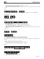
4.3.1
Reading telegram
Master:
STX
ADR
COD
NUM
DMR
...
DMR
ETX
BCC
SCA06 | 14
WEGTP Protocol
COD: code for reading Æ 0x3C (hexadecimal); 60 (decimal); ‘<’ (ASCII)
NUM: number of parameters read. Range from 1… 6.
DMR: Number of the requested parameter. The number of DMRs must be equal the value set in the NUM
byte.
Slave:
ADR
DSV
...
DSV
BCC
or
ADR
NAK
DSV: value of the requested parameter. The number of DSVs is equal to the value set in the NUM byte
Remembering that:
DMR
PHi PLo
4.3.2
DSV
VHi VLo
Writing telegram
Master:
STX
ADR
COD
NUM
DMW
...
DMW
ETX
BCC
COD: code for writing
0x3E (hexadecimal); 62 (decimal); ‘>’ (ASCII)Æ saving on the EEPROM
0x3D (hexadecimal); 61 (decimal); ‘=’ (ASCII)Æ without saving on the EEPROM
NUM: number of parameters written. Range from 1… 6.
DMW: number and content for the parameter. The number of DMWs must be equal to the value set in the
NUM byte.
Slave:
ADR
ACK
or
ADR
NAK
Remembering that:
PHi
4.4
DMW
PLo VHi
VLo
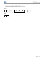
EXAMPLE OF TELEGRAMS USING THE WEGTP PROTOCOL
All the following examples consider that the servo drive is programmed with the address 1, then the field ADR is
set for 41.
Example 1: reading of two parameters of the servo drive:
Servomotor speed: P0002 (assuming P0002 at 1200rpm = 0x04B0).
Status of the servo drive - P0006 (assuming P0006 at 1 = 0x0001).
Master:
0x02
STX
0x41
ADR
0x3C
COD
0x02
NUM
0x00 0x02
DMR:P0002
Parâmetro
0x00 0x06
DMR:P0006
Parâmetro
0x03
ETX
0x7A
BCC
Slave:
0x41 0x04 0xB0
ADR DSV:1200
Valor
0x00 0x01
DSV:1
Valor
0xF4
BCC
Example 2: change the servo drive to ladder mode:
SCA06 | 15
WEGTP Protocol
For this, it is necessary to put the parameter P0202 in 4.
Writing telegram saving on the EEPROM.
P0202 = 4 (202 in decimal = 0x00CA, 4 in decimal = 0x0004)
Master:
0x02
STX
0x41
ADR
0x3E
COD
0x01
NUM
0x00
0xCA 0x00 0x04 0x03
DMW: P0202 = 4
ETX
Parâmetro
Valor
0xB1
BCC
Slave:
0x41 0x06
ADR ACK
SCA06 | 16
FAULTS AND ALARMS RELATED TO WEGTP COMMUNICATION
5 FAULTS AND ALARMS RELATED TO WEGTP COMMUNICATION
A00128/F00028 – TIMEOUT AT THE TELEGRAM RECEPTION
Description:
Alarm that indicates serial communication fault. It indicates the equipment stopped receiving valid serial
telegrams for a period longer than that set on P00663.
Actuation:
The parameter P00663 allows setting a time within which the servo drive must receive at least one valid
telegram via serial RS485 interface – with correct address and error checking field – otherwise it will be
considered that there was a problem in serial communication. The time starts to be counted after receiving the
first valid telegram. This function can be used for any serial protocol supported by the servo drive.
After identifying the timeout in the serial communication, it will be signaled, through the HMI, the alarm message
A00128 - or fault F00028, depending on the setting on P00662. For alarms, in case the communication is
restored, the alarm indication will be removed from the HMI.
Possible Causes/Correction:
Check network installation, broken cable or fault/poor contact on the connections with the
network/grounding.
Ensure the master always sends telegrams to the equipment in a time shorter than that set on P00663.
Disable this function on P00663.
SCA06 | 17
Appendices
I. APPENDICES
APPENDIX A. ASCII TABLE
Table I.1: ASCII Characters
Dec
Hex
Chr
0
1
2
3
4
5
6
7
8
9
10
11
12
13
14
15
16
17
18
19
20
21
22
23
24
25
26
27
28
29
30
31
00
01
02
03
04
05
06
07
08
09
0A
0B
0C
0D
0E
0F
10
11
12
13
14
15
16
17
18
19
1A
1B
1C
1D
1E
1F
NUL
SOH
STX
ETX
EOT
ENQ
ACK
BEL
BS
HT
LF
VT
FF
CR
SO
SI
DLE
DC1
DC2
DC3
DC4
NAK
SYN
ETB
CAN
EM
SUB
ESC
FS
GS
RS
US
(Null char.)
(Start of Header)
(Start of Text)
(End of Text)
(End of Transmission)
(Enquiry)
(Acknowledgment)
(Bell)
(Backspace)
(Horizontal Tab)
(Line Feed)
(Vertical Tab)
(Form Feed)
(Carriage Return)
(Shift Out)
(Shift In)
(Data Link Escape)
(Device Control 1)
(Device Control 2)
(Device Control 3)
(Device Control 4)
(Negative Acknowledgement)
(Synchronous Idle)
(End of Trans. Block)
(Cancel)
(End of Medium)
(Substitute)
(Escape)
(File Separator)
(Group Separator)
(Record Separator)
(Unit Separator)
Dec
Hex
Chr
Dec
Hex
Chr
Dec
Hex
Chr
32
33
34
35
36
37
38
39
40
41
42
43
44
45
46
47
48
49
50
51
52
53
54
55
56
57
58
59
60
61
62
63
20
21
22
23
24
25
26
27
28
29
2A
2B
2C
2D
2E
2F
30
31
32
33
34
35
36
37
38
39
3A
3B
3C
3D
3E
3F
Sp
!
"
#
$
%
&
'
(
)
*
+
,
.
/
0
1
2
3
4
5
6
7
8
9
:
;
<
=
>
?
64
65
66
67
68
69
70
71
72
73
74
75
76
77
78
79
80
81
82
83
84
85
86
87
88
89
90
91
92
93
94
95
40
41
42
43
44
45
46
47
48
49
4A
4B
4C
4D
4E
4F
50
51
52
53
54
55
56
57
58
59
5A
5B
5C
5D
5E
5F
@
A
B
C
D
E
F
G
H
I
J
K
L
M
N
O
P
Q
R
S
T
U
V
W
X
Y
Z
[
\
]
^
_
96
97
98
99
100
101
102
103
104
105
106
107
108
109
110
111
112
113
114
115
116
117
118
119
120
121
122
123
124
125
126
127
60
61
62
63
64
65
66
67
68
69
6A
6B
6C
6D
6E
6F
70
71
72
73
74
75
76
77
78
79
7A
7B
7C
7D
7E
7F
`
a
b
c
d
e
f
g
h
i
j
k
l
m
n
o
p
q
r
s
t
u
v
w
x
y
z
{
|
}
~
DEL
SCA06 | 18
WEG Equipamentos Elétricos S.A.
Jaraguá do Sul – SC – Brazil
Phone 55 (47) 3276-4000 – Fax 55 (47) 3276-4020
São Paulo – SP – Brazil
Phone 55 (11) 5053-2300 – Fax 55 (11) 5052-4212
[email protected]
www.weg.net