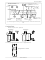
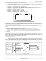
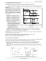
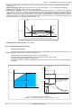
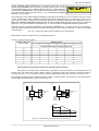
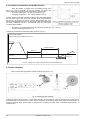
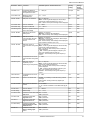
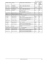
1
® TWERD Power Electronics TWERD Vector controlled frequency converter MFC710 400V MFC710 500V MFC710 690V type User's Manual www.twerd.pl TWERD Power Electronics ul. Konwaliowa 30 87-100 Toruń, Poland tel. +48 56 654 60 91 fax +48 56 654 69 08 [email protected] www.twerd.pl Information furnished is believed to be accurate and reliable. However, TWERD Power Electronics assumes no responsibility for the consequences of use of such information nor for any infringement of patents or other rights of third parties which may result from its use. Furthermore TWERD Power Electronics are not responsible for any damages resulting from the use of converters outside its intended purpose. No license is granted by implication or otherwise under any patent or patent rights of TWERD Power Electronics. Specification mentioned in this publication are subject to change without notice. This publication supersedes and replaces all information previously supplied. TWERD Power Electronics products are not authorized for use as critical components in life support devices or systems without express written approval of TWERD Power Electronics Company. TWERD logo is a trademark of TWERD Power Electronics. For more information contact out technical support at: [email protected] All trademarks and registered trademarks are the property of their respective owners. User manual version: 3_mfc710_en_v.5.84,0, 21/8/2015 MFC710 User's Manual Contents Technical data.......................................................................................................................................................................5 1. Conditions of safe operation.............................................................................................................................................9 1.1 Warnings...................................................................................................................................................................9 1.2 Basic rules.................................................................................................................................................................9 1.3 Operation list.............................................................................................................................................................9 1.4 Environmental conditions.........................................................................................................................................9 1.5 CE certificates.........................................................................................................................................................10 2. Installation of the frequency converter............................................................................................................................11 2.1 Connection of a power circuits................................................................................................................................11 2.1.1. Safety rules....................................................................................................................................................12 2.1.2. Electromagnetic compatibility (EMC) rules....................................................................................................12 2.2 Connection of control circuits..................................................................................................................................14 2.3. Installation figures..................................................................................................................................................15 3. Control panel...................................................................................................................................................................18 3.1. Viewing and changing parameters value...............................................................................................................19 3.2. Blocking parameters and access control...............................................................................................................19 3.2.1. Unblocking changing of parameters..............................................................................................................20 3.2.2. Blocking by an access code..........................................................................................................................20 3.2.3. Unblocking changing of parameters of the electric drive, blocked by a code...............................................20 3.2.4. Activating protection by access code ...........................................................................................................21 3.2.5. Deactivating protection by access code........................................................................................................21 3.2.6. Change of access codes..............................................................................................................................21 3.2.7. Loading of factory options of the converter...................................................................................................21 3.2.8. Factory values of access codes....................................................................................................................21 3.2.9. Full pointers...................................................................................................................................................21 3.3 Change of displayed values....................................................................................................................................21 3.4. Contrast regulation.................................................................................................................................................22 4. Configuration of the frequency converter........................................................................................................................22 4.1. Setting nominal parameters of the motor...............................................................................................................22 4.1.1. Preparation for operation in a vector control mode ......................................................................................23 4.2. Control....................................................................................................................................................................23 4.2.1 Structure of control.........................................................................................................................................23 4.2.2 Control from the control panel........................................................................................................................26 4.2.3 Control through terminal connections.............................................................................................................26 4.2.4. Work with constant speeds...........................................................................................................................27 4.2.5. Motopotentiometer.........................................................................................................................................27 4.2.6. Other possibilities of the frequency converter control...................................................................................28 4.2.7. Configuration of digital and analog inputs and outputs.................................................................................28 4.3. Configuration of the electric drive ..........................................................................................................................31 4.3.1 Establishing dynamic characteristics and ways of halting the electric drive..................................................31 4.3.2. Formation of U/f characteristic .....................................................................................................................31 4.3.3. Elimination of frequencies ...........................................................................................................................32 4.3.4. DC (direct current) braking............................................................................................................................32 4.3.5 Mechanical brake...........................................................................................................................................32 4.3.6. Flying start.....................................................................................................................................................33 4.4. Protection and blocking..........................................................................................................................................33 4.4.1 Current, frequency and the torque limitations...............................................................................................33 4.3.2 Blocking a direction of drive rotation..............................................................................................................33 4.3.3 Blocking the electric drive operation...............................................................................................................33 4.4.4. Thermal protection of the drive......................................................................................................................34 5. The first start...................................................................................................................................................................36 5.1. Vector control mode. Identification run..................................................................................................................36 5.1.1. Stages of identification run............................................................................................................................36 5.1.2. Switching on identification run.......................................................................................................................36 5.2. Storing and reading of options for 4 different drives..............................................................................................37 6. Failures and warnings.....................................................................................................................................................38 6.1. Messages on failures and warnings on the control panel .....................................................................................38 6.2. Deleting failure message. Automatic restarts........................................................................................................38 6.2.1. Manual deleting.............................................................................................................................................38 6.2.2. Deleting through a digital input of the converter ...........................................................................................38 6.2.3. Remote deleting through RS link ..................................................................................................................38 6.2.4. Readiness to restart if the reason of failure has not disappeared.................................................................38 6.2.5. Automatic restarts..........................................................................................................................................39 6.3. Codes of failures and warnings..............................................................................................................................39 6.4. Failure log...............................................................................................................................................................41 7. Sets of factory parameters..............................................................................................................................................42 8. PID controller..................................................................................................................................................................43 8.1. Turning on and a configuration of the PID controller.............................................................................................43 8.2. Limitation of saturation and SLEEP function..........................................................................................................44 TWERD Power Electronics 3 Contents 9. Reeler calculator.............................................................................................................................................................44 9.1. Turning on and configuration of RC.......................................................................................................................45 10. Pump Group Controller.................................................................................................................................................45 10.1 Parameters of a pump group controller................................................................................................................46 10.2 Turning on pump group controller.........................................................................................................................46 10.3 An operating mode with the PID controller and a mode of direct control..............................................................46 10.4 A configuration of pump amount and operating modes of separate pumps - blocking of pumps........................47 10.5 Monitoring work of pumps.....................................................................................................................................47 10.6 Conditions of switching on/off additional pump.....................................................................................................48 10.6.1 Priority of switching on/off additional pumps...............................................................................................48 10.7 Automatic replacement of pumps ........................................................................................................................49 11. Advanced programming of MFC710.............................................................................................................................50 11.1 Characteristic Points (PCH) .................................................................................................................................50 11.2. PCH and the pointers – how does it work............................................................................................................50 11.3. Modification of standard control ..........................................................................................................................50 11.4. The control panel – defining displayed values ....................................................................................................51 11.5 The control panel - definition of user referencing-units.........................................................................................51 11.6. System of rotation counter...................................................................................................................................52 12. PLC controller...............................................................................................................................................................52 12.1 Universal functional blocks....................................................................................................................................52 12.2. Sequencer device.................................................................................................................................................53 12.3 Multiplexers MUX1 and MUX2..............................................................................................................................53 12.4 Curve shaping unit................................................................................................................................................54 12.5 Constants..............................................................................................................................................................54 12.6 Example of PLC use..............................................................................................................................................55 13. Control of the frequency converter by means of connection RS..................................................................................56 13.1 Parameters which concern communication through RS.......................................................................................56 13.2 Map of registers accessible through RS link.........................................................................................................57 13.3 Handling of connection errors...............................................................................................................................58 14. Information from the manufacturer...............................................................................................................................58 Appendix A – Table of Characteristic Points......................................................................................................................59 Appendix B - Table of Functions of Universal Blocks.........................................................................................................63 Appendix C – Table of MFC710 frequency converter's parameters...................................................................................67 GROUP 1 – CONFIGURATION OF THE DRIVE..........................................................................................................68 GROUP 2 – REFERENCING-UNITS AND CONTROL.................................................................................................72 GROUP 3 – FAILURES.................................................................................................................................................76 GROUP 4 – PARAMETERS BLOCKING, CONFIGURATION OF: RS, DISPLAYING AND USER REFERENCINGUNITS............................................................................................................................................................................78 GROUP 5 – PUMP GROUP CONTROLLER, BLOCKS OF PLC CONTROLLER........................................................80 GROUP 6 – PLC CONTROLLER – UNIVERSAL BLOCKS..........................................................................................83 DECLARATION OF CONFORMITY....................................................................................................................................85 4 TWERD Power Electronics MFC710 User's Manual Technical data This User's manual refers to frequency converters MFC710 type. These frequency converters are made in three different supply voltage: 3x400V (typical) and 3x500V (optional) and 3x690V (optional). Table 0.1 shows the technical data common to the series of frequency converters MFC710. Table 0.1 – Technical data common for frequency converters of the MFC710 series Three-phase power: 400V or 500V*) or 690V*) (-15% +10%), 45 ... 66Hz *) Power supply Voltage Uin / freq. depending on the type of a frequency converter; information on the supply voltage is also placed on the nameplate Output Output voltage 0 ... Uin [V] Frequency 0,0 ... 400Hz Frequency resolution 0.01Hz (vector) Control system Control inputs/outputs Communication Special functions Modulator SVPWM Operation mode U/f (linear, exponential), Vector DTC-SVM without sensor Vector DTC-SVM with sensor of the rotor position Switching frequency 2 ... 15kHz, also random carrier Rotation speed setting Analog inputs, control panel, motopotentiometer, PID controller, communication unit RS232 or RS485 and other possibilities. Resolution of 0.1 % for analog inputs or 0.1Hz / 1 rpm for the control panel i RS Analog inputs 3 analog inputs: AI0: voltage mode 0(2) ... 10V, Rin ≥ 200kΩ; AI1, AI2: voltage mode 0(2) ... 10V, Rin ≥ 100kΩ; current mode 0(4)...20mA, Rin = 250Ω, Operation mode and polarity are chosen by parameters and switches. Accuracy: 0.5 % of the full range. Digital inputs 6 digital separated inputs 0/(15...24)V, Rin ≥ 3kΩ Analog outputs 2 outputs 0(2)...10V / 0(4)...20mA – configuration by parameters and switches, accuracy:0.5 % Digital outputs 3 relays K1, K2 and K3 – breaking capacity: 250V/1A AC, 24V/1A DC, 1 open collector output 100mA/24V. Fully programmable signal source Encoder interface Possibility of direct connection of incremental encoder (5V, line driver, <250kHz). Recommended pulse rate: 1024 ÷ 2048. Connectors RS232, RS485 with optoisolation Communication protocol MODBUS RTU. Function 3 (Read Register); Function 6 (Write Register). Baud-rate 9600, 19200, 38400 or 57600 bit/s Application Remote control of unit operation and programming of all parameters of the frequency converter. PID controller Choice of referencing-unit signal source and feedback signal source, possibility of inverting polarity of an control error signal , SLEEP function and output erasing on STOP signal, limitation of an output value. PLC controller Possibility of taking control over converter's operation, START / STOP system, direction of rotation and frequency, possibility of controlling any external process without connection of external PLC controller. 48 universal functional blocks, 43 functions: simple logic and arithmetic blocks; block of 8state sequencer, 2 multiplexers with 8 inputs, curve shaping unit, maximum execution time of the PLC program: 10ms. Control of pumps group Up to 5 pumps in a cascade Control with use of PID controller or by direct referencing Each pump can be programmed individually for operation from a frequency converter or from the mains; possibility of pump blocking Automatic replacement of the pump after a preset time of operation There are 9 available set of predefined parameters: - Local: control from keyboard - Remote: control through digital or analog inputs - Local/Remote: choice between local and remote Set of Predefined - PID: speed regulated by PID controller (Factory) Parameters - Motopotentiometer: control with “increase/decrease” signals from digital inputs - Constant frequencies: operation with constant frequencies, switching through digital inputs - Torque regulation: setting the torque by signal from digital input, vector control - Pumps: control of pump group - Reeler: setting the torque with the reeler calculator, vector control Definition of User's values for direct observation of the process variables- choice of measurement unit, scale and data source (e.g. from PLC controller) Additional functions of the panel Definition of User's referencing-device for direct changing of the process variables – choice of measurement unit and scale LCD contrast adjustment TWERD Power Electronics 5 Technical data Protections Short-circuit Short-circuit on unit output Overcurrent Instantaneous value 3.5 In;; effective value 2.5 In Overvoltage AC/DC MFC710 400V: 1,43 Uin (Uin = 400V) AC; 750V DC MFC710 500V: 1,32 Uin (Uin = 500V) AC; 900V DC MFC710 690V: 1,28 Uin (Uin = 690V) AC; 1200V DC Undervoltage 0.65 Uin Thermal: device Heatsink's heat sensor Thermal: motor I2t limit, motor heat sensor (PTC type) Supervision of communication with control panel Established permissible time of connection absence Supervision of communication through RS Established permissible time of connection absence Control of analog inputs Check of absence of “living null” in modes 2... 10V and 4... 20mA Control of a load symmetry E.g. break in one of the motor phases Underload Protection from operating without any load Stall Protection against stall of a motor Table 0.2a – Technical data of frequency converters of the MFC710 400V series, depending on a type Type of frequency converter Constant-torque load (max. overload 1.5) Variable-torque load (max. overload 1.11)) Ip [A] Iz [A] 2.25 6.3 PN [kW] IN [A] PN2 [kW] IN2 [A] MFC710/0.37kW 0.37 1.5 0.55 2.0 MFC710/0.55kW 0.55 2.0 0.75 2.5 3.0 6.3 MFC710/0.75kW 0.75 2.5 1.1 3.5 3.75 6.3 MFC710/1.1kW 1.1 3.5 1.5 4.0 5.25 6.3 MFC710/1.5kW 1.5 4.5 2.2 5.5 6.0 6.3 MFC710/2.2kW 2.2 5.5 3 7.8 8.3 10 3 7.8 4 9.5 11.7 10 MFC710/3kW MFC710/4kW 4 9.5 4 9.5 15.8 16 MFC710/5.5kW 5.5 12 7.5 16 18 20 MFC710/7.5kW 7,5 17 11 23 25 25 MFC710/11kW 11 24 15 29 36 30 MFC710/15kW 15 30 18 37 45 50 MFC710/18.5kW 18.5 39 18.5 39 60 59 MFC710/22kW 22 45 30 60 68 63 MFC710/30kW 30 60 37 75 90 80 MFC710/37kW 37 75 45 90 112 100 MFC710/45kW 45 90 55 110 135 125 MFC710/55kW 55 110 75 150 165 160 MFC710/75kW 75 150 90 180 225 200 MFC710/90kW 90 180 110 210 270 225 MFC710/110kW 110 210 132 250 315 315 MFC710/132kW 132 250 160 310 375 315 MFC710/160kW 160 310 180 375 465 400 MFC710/200kW 200 375 250 465 570 500 MFC710/250kW 250 465 250 465 690 630 MFC710/315kW 315 585 355 650 850 800 MFC710/355kW 355 650 400 730 940 800 MFC710/400kW 400 730 400 730 1100 800 MFC710/450kW 450 820 500 910 1190 1000 MFC710/500kW 500 910 560 1020 1365 1250 1) for ambient temperature < 35 0C PN – nominal output power when the maximum overload current Ip is about 1.5 IN (constant-torque load) 6 TWERD Power Electronics MFC710 User's Manual IN – nominal output current at PN PN2 – nominal output power when the maximum overload current Ip is about 1.1 IN2 (pumps, fans) IN2 – nominal output current at PN2 IP – overload current: 60 seconds every 10 minutes IZ – maximum nominal current protection Table 0.2b – Technical data of frequency converters of the MFC710 500V series, depending on a type Constant-torque load Variable-torque load Type (max. overload 1.5) (max. overload 1.11)) MFC710/500/... IN [A] PN2 [kW] IN2 [A] PN [kW] Ip [A] Iz [A] 0,37kW 0,37 1,2 0,55 1,6 1,8 6,3 0,55kW 0,55 1,6 0,75 2,0 2,4 6,3 0,75kW 0,75 2,0 1,1 2,8 3,0 6,3 1,1kW 1,1 2,8 1,5 3,6 4,2 6,3 1,5kW 1,5 3,6 2,2 4,4 5,4 6,3 2,2kW 2,2 4,4 3 6,0 6,6 10 3,0kW 3 6,3 4 8,0 9,5 10 4,0kW 4 8,0 4 8,0 12 16 5,5kW 5,5 10 7,5 14 15 20 7,5kW 7,5 14 11 20 21 25 11kW 11 20 15 24 30 30 15kW 15 24 18 32 36 50 18.5kW 18,5 32 18,5 32 48 59 22kW 22 37 30 50 56 63 30kW 30 50 37 60 75 80 37kW 37 60 45 72 90 100 45kW 45 72 55 90 108 125 55kW 55 90 75 120 135 160 75kW 75 120 90 150 180 200 90kW 90 150 110 180 225 225 110kW 110 180 132 200 270 315 132kW 132 200 160 250 300 315 160kW 160 250 180 300 375 400 200kW 200 300 250 380 450 500 250kW 250 380 250 475 570 630 315kW 315 475 355 520 713 800 355kW 355 520 400 584 780 800 400kW 400 584 450 656 876 900 450kW 450 656 500 728 984 1000 500kW 500 728 560 816 1092 1250 560kW 560 816 630 900 1224 1250 PN – nominal output power when the maximum overload current Ip is about 1.5 IN (constant-torque load) IN – nominal output current at PN PN2 – nominal output power when the maximum overload current Ip is about 1.1 IN2 (pumps, fans) IN2 – nominal output current at PN2 IP – overload current: 60 seconds every 10 minutes IZ – maximum nominal current protection TWERD Power Electronics 7 Technical data Table 0.2c – Technical data of frequency converters of the MFC710 690V series, depending on a type Type MFC710/690/... Variable-torque load (max. overload 1.11)) Constant-torque load (max. overload 1.5) PN [kW] IN [A] PN2 [kW] IN2 [A] 15kW 15 18 18 21 26 18,5kW 18 23 22 26 35 22kW 22 26 30 35 39 30kW 30 36 37 43 52 37kW 37 43 45 52 65 45kW 45 52 55 64 78 55kW 55 64 75 87 95 75kW 75 87 90 104 130 90kW 90 104 110 121 156 110kW 110 121 132 144 182 132kW 132 144 160 179 217 160kW 160 179 180 219 268 180kW 180 202 200 242 300 200kW 200 219 250 266 329 250kW 250 266 315 329 398 315kW 315 329 355 393 491 355kW 355 375 400 420 530 400kW 400 *) 400 420 530 500kW 500 *) 500 500 550 560kW 560 *) 560 560 615 630kW 630 *) 630 650 715 800 *) 800 800 920 800kW *) For frequency converters at nominal power 400 kW and above, the range of overload is determined in consultation with the Customer PN – nominal output power when the maximum overload current Ip is about 1.5 IN (constant-torque load) IN – nominal output current at PN PN2 – nominal output power when the maximum overload current Ip is about 1.1 IN2 (pumps, fans) IN2 – nominal output current at PN2 IP – overload current: 60 seconds every 10 minutes 8 Ip [A] TWERD Power Electronics MFC710 User's Manual 1. Conditions of safe operation 1.1 Warnings • After connecting converter to the supply grid, internal circuit components (except In/Out clamps) are on the supply grid potential. Touching them can cause an electric shock. • When you connect the converter to the supply grid there is a dangerous voltage on clamps U, V, W, even when the motor does not work. • After disconnecting the device from the supply grid the dangerous voltage is still present for about 5 minutes. 1.2 Basic rules • • • • • Don’t make any connections when the converter MFC710 is connected to the mains. Don’t connect mains voltage to output clamps U, V, W. Don’t measure the voltage endurance of any unit devices. To measure the cables insulation it is necessary to disconnect them from the converter. Don’t touch integrated circuits and any other parts on the converter's electronic board, as they can be damaged by electrostatic discharge. • Don't connect any capacitors to motor wires intended for improvement of power factor • Don't measure output voltage of converter using digital voltmeters 1.3 Operation list The operations applied at installation and the first start-up of the electric drive ✔ After unpacking the converter, it is necessary to check up visually presence of damages which could arise during transport. ✔ Check up the correspondence between the delivered frequency converter and the order - check up the ratings plate on the case. Delivery includes: • the frequency converter with the User's Manual, • a choke – if it was ordered, recommended for rated power 5.5 kW and above, • a ferrite ring or RFI filter - depending on the order. ✔ Check up the correspondence between conditions in which the converter will be used and conditions of an environment for which it is designed (section 1.4). ✔ Installation of the frequency converter should be made according to principles of safety and EMC rules, listed in section 2. ✔ Remove the protective film from the display ✔ Choose a configuration of the frequency converter and realize it according to this User's Manual. 1.4 Environmental conditions Degree of pollution During design second degree of pollution has been assumed, at which there are normally only non-conducting pollution. However there is a probability of temporary conductivity caused by a condensation, when the converter doesn't work. In case the environment in which the frequency converter will work, contains pollution which can influence its safety, it is necessary to apply appropriate counteraction, using, for example, additional cases, air channels, filters etc. Climatic conditions Installation site 1 from -10°C to +55°C from -25°C to +55°C from 5% to 95% from 5% to 95% Temperature Relative humidity Air pressure 1 During warehousing During transport from -25°C to +70°C Protective packing Max 95% Short-term, insignificant condensation on the external side of the converter case is permitted only when converter doesn't work. from 86 kPа to 106 kPа from 86 kPa to 106 kPa from 70 kPa tо 106 kPa For nominal load temperature 40oC was assumed, however for lower loads higher temperatures are acceptable. TWERD Power Electronics 9 Section 1. Conditions of safe operation 1.5 CE certificates Frequency converters of MFC710 fulfill the fundamental requirements of following instructions of the new approach: • the Instruction low-voltage LVD 2006/95/WE, • the Instruction EMC 2004/108/WE. Mentioned above instructions are fulfilled only after installation of the frequency converter and configuration of the electric drive according to instructions of installation principles and the principles of safety resulted below. User is obliged to fulfill this requirements. The declaration of conformity is in the end of the instruction. Safety IEC/EN 50178:2003 Electronic products which are used in installations of the high power. IEC/EN 60204-1:2001 Safety of machines. The electric equipment of machines. Part 1: General requirements. Electromagnetic compatibility IEC/EN 61800-3:1999/A11:2002 Electric power drives with regulated speed. Electromagnetic compatibility (EMC) in consideration of special methods of research IEC/EN 61800-3/A11 first environment Conducted emission Distribution is unlimited - with use of installation principles (section 2.1.2) and the equipment (section 2.1.2 without item e)). Distribution is limited - with use of installation principles (section 2.1.2) and the equipment (section 2.1.2 without item d) and e)). IEC/EN 61800-3/A11 first environment Radiation emission Resistance Distribution is limited - with use of installation principles (section 2.1.2) and the equipment (section 2.1.2 without item e)). IEC/EN 61800-3/A11 second environment Distribution is unlimited - with use of installation principles (section 2.1.2) and the equipment (section 2.1.2 without item d) e)). IEC/EN 61800-3/A11 second environment Distribution is unlimited - with use of installation principles (section 2.1.2) and the equipment (section 2.1.2 without item d) e)). IEC/EN 61800-3/A11 first and second environment The first environment: includes the equipment plugged in a low-voltage supply grid which powers apartment buildings. The second environment: includes the equipment plugged in a supply grid which doesn't power living quarters. Limited distribution: type of distribution at which the manufacturer limits delivery of the equipment to suppliers, clients or users who separately or together have the competence in the field of including electromagnetic compatibility at use of frequency converters MFC710. Distribution unlimited: type of distribution at which delivery does not depend on the technical competence of the client or the user in the field of requirements which concern to electromagnetic compatibility at use of converters MFC710. The frequency converter set up in the first environment without external supply grid filter RFI does not exceed value of emission which is admissible for the limited distribution. However there are exceeded limits of value of admissible emission for unlimited distribution. That’s why: The product belongs to a class with the limited distribution which is certain in norm IEC 61800-3. In the housing environment this product can cause radio-interferences and in this case user has to accept additional preventing measures. By analogy in the second environment in which for realization of requirements of emission according to unlimited distribution is not obligatory to use filter RFI, but it is necessary to consider an possibility of radio-interference occurrence. In IT grids usage of asymmetric filters of high frequency (condensers Y and CY) to reduce emission of interference, ruins the concept of the distributive grid isolated from the ground. Additional grounded impedances can become threat of safety in such systems. For technical reasons in some applications (current higher than 400A) fulfilling requirements of EMC is not possible. In such cases user and manufacturer should decide on ways of satisfying EMC requirements in this particular application. 10 TWERD Power Electronics MFC710 User's Manual 2. Installation of the frequency converter 2.1 Connection of a power circuits The MFC710 converter is powered by the three-phase power supply through the L1, L2, L3 input terminals. In some implementations, there is a necessary to connect auxiliary power source for supply internal fans. In the fig. 2.1 the scheme of power circuits connections is presented. Diameters of wires and the parameters of chokes should be selected depending on current of a load. Appropriate protection values are listed in table 0.2 and recommended values of wires cross-section are listed in table 2.1. The frequency converter is supplied with appropriate resources, protected from corrosion, dedicated to make appropriate connections. Additional information about external connections can be found in section 2.1.1 under the “Equipotential connections” and in section 2.1.2. In order to comply with EU directives of electromagnetic compatibility (EMC) application of a four-wire shielded cable (three phases + earth wire) is recommended to fed the motor. Type of mains choke and protections is available at producer's representative. It is strongly recommended not to use any switches or contactors at the converter output that could disconnect system during the run. 1) ATTENTION! Shown circuit has terminals for illustration only and does not show their actually position on the drive Power switch Dynamic braking resistor (option) +BR (+DC)2) Overcurrent protection -BR (BR)2) Shield cable recommended 5) Main power supply L1 L1 L2 6) L2 6) L3 L3 PE MFC710 6) U U V V W W +M 7) Auxiliary power supply 4) 3) L ~ PE PE PE N +D L M - Do not use any contactors between converter output and motor! - Output voltage can be measured correctly only with an electromagnetic voltometer! N 1) +BR(+DC), -BR(BR) connectors are only present in frequency converters ready to work with the breaking resistor (this converters are equipped with breaking transistors - frequency converters at 18.5kW and below are equipped as standard with breaking transistor, frequency converters at 22 kW and above are assembled in breaking transistor optionally). Attention: frequency converters also can have +DC, -DC connectors. These are connectors of internal DC circuit. Do not connect breaking resistor to this connectors! 2) Marks used for converters 22kW and above. 3) In some frequency converters (30kW..75kW and others) internal fan must be powered from an external power source. 4) A typical external supply voltage is 230V AC. Optionally, it can be 3x400V AC or other according to individual orders. For this reason, depending on the version, there can be various power cords numbers and their markings. 5) For rated power 5.5 kW and above 3 phase choke is recommended. 6) Frequency converters 450kW and above have 6 input clamps and are prepared to work with 12-pulse input system. 7) In a high power inverters can occur DC terminals: +M,+D. Depending on the individual settings, please connect a choke, or do short-out by jumper. Fig. 2.1 Connection of power circuits to MFC710 converter Table 2.1. Long-term current load of copper wires with PVC insulation in temperature +40oC on the example of the cable HELUKABEL TOPFLEX-EMV-3 PLUS-2YSLCY-J 600/1000 V No.cores x cross-sec. [mm 2] Power ratings with 3 loaded cores [A] No.cores x cross-sec. [mm2] Power ratings with 3 loaded cores*) [A] 3x1,5 + 3G 0,25 15 3x50 + 3G 10 146 3x2,5 + 3G 0,5 22 3x70 + 3G 10 180 3x4 + 3G 0,75 29 3x95 + 3G 16 217 3x6 + 3G 1 38 3x120 + 3G 16 254 3x10 + 3G 1,5 53 3x150 + 3G 25 291 3x16 + 3G 2,5 71 3x185 + 3G 35 332 3x25 + 3G 4 93 3x240 + 3G 42,5 394 3x35 + 3G 6 117 TWERD Power Electronics PE PE PE Fig. 2.2 HELUKABEL TOPFLEX-EMV-3 PLUS-2YSLCY-J 600/1000 V 11 Section 2. Installation of the frequency converter 2.1.1. Safety rules Equipotential connections The protection against indirect touching live parts consists of automatic switching off by special short-circuit protection (or differential-current protection) or voltage limitation to a level not exceeding acceptable values, in case of an insulation failure. The short circuit to ground at the frequency converter output can be not detected by short-circuit protection, devices due to DC-link circuit. The protection against phase-to-phase and phase-to-ground short-circuit on the output of the converter is provided. However this protection is based on IGBT transistors blocking, what does not conform to the requirements of fire-prevention protection. Due to that, for safety of staff, it is necessary to make local equipotential connections. In the frequency converter there are provided appropriate terminals, properly marked, protected from corrosion to make equipotential connections. Protection The minimum values of input wire short-circuit protection are presented in the table 0.2. Usage of gG or aM fuses is allowed in the circuits, however taking into account necessity of protection of the rectifier bridge of the frequency converter, the best solution is gR or aR fuses. You can use overcurrent protection, but the response time of such devices is longer than properly chosen fuse. Frequency converter is protected from: drive overloading, motor overheating, under- and overvoltage in an DC link circuit of the converter, a short-circuit at the converter output (it protects converter only!!). Usage of differential-current protection due to electrical shock prevention can appear unfavorable, since it can trigger due to temporary or constant leakage current of the power drive system, working in normal conditions. In case of usage of the differential-current protection devices you may use only circuit breakers of a B type, due to different nature of a differential current. Disconnecting device In order to comply with EU directives, according to IEC/EN 60204-1:2001, power drive, which consists of a frequency converter and electrical machine should be supplied with a device for disconnecting power supply. This device should be one of listed below: • separator (with or without fuses), category of usage AC-23B fulfilling the requirements EN 60947-3, • disconnector (with fuses or without), disconnecting a load circuit before opening main contacts, conforming the EN 60947-3 requirements, • tripper conforming the EN 60947-2 requirements. User is obliged to fulfil this requirement. Emergency stop In order to comply with EU directives and IEC/EN 60204-1:2001 and for personnel safety and equipment, it is necessary to use an emergency stop switch, which has higher priority than other functions, irrespective of operating mode. The key STOP on operator panel cannot be treated as the switch of abnormal break, because it doesn't disconnect a frequency converter from power supply. User is obliged to fulfill this requirement. Casing The casing conforms to the requirements of a IP20 protection degree. The surface, on which the control panel is situated fulfills the requirements of a IP40 protection degree. The casing was designed in such a manner that it cannot be removed without usage of tools. Capacitors discharging In a DC link circuit of a frequency converter there is a capacitor battery with relatively high capacity. After turning off of a supply voltage in its clamps dangerous voltage is present for a certain time. It is necessary to wait for 5 minutes before making connections on clamps of power terminal strip of a frequency converter. The information about danger of such voltage is placed also on terminal strip cover. 2.1.2. Electromagnetic compatibility (EMC) rules The installation principles reducing EMC problems are divided into four groups. To achieve full success it is necessary to apply all principles listed below. Not applying to one of principles ruins the effect of others. • separation, The basic way of connecting the filter, the frequency converter and the • equalizer connections, motor is presented in the figure below • shielding, • filtration. Separation Power cables (supplying, motor's) must be separated from signal wires. It is necessary to avoid parallel leading of power and signal wires in the common wire channels, and especially in group of cables. The crossing of power cables and signal cables under a right angle is allowed. 12 TWERD Power Electronics MFC710 User's Manual Equipotential connections The frequency converter and the filter should be mounted as close as possible, preferably on a common metal plate which act as a ground. For this purpose you can use, a mounting plate or a back wall of a case for example. The casing of the frequency converter, the filter and the metal plate shouldn't be coated with any insulation materials. It is necessary to pay attention to an opportunity of oxidation of a surface that results in deterioration of contact. For limitation of asymmetric disturbance level, it is necessary to apply many connections of the cable shielding to ground. Additional information about equipotential connection can be found in section 2.1.1. Shielding Wires between the mains filter and the frequency converter are not necessary for shielding, if their length doesn't exceed 300mm. In case the length of conductors exceeds 300mm it is necessary to use the shielded wires. Completely shielded cable is a cable which fully complies with requirements of interference radiation according to EN 55011 norms. Such cable should have the screen consisting of spiral metallized aluminium foil and tinned copper plait with a puls-duty factor of not less than 85 %, not separated galvanically. Connection of the cable ends to ground is obligatory. It is necessary to use grounding of the cable shielding on whole section of a cable, on both ends. For this purpose a special EMC grommets are used. They provide valid contact of cable shielding to the case of the equipment. In addition it is necessary to use special cable clips to connect it to back wall of a case for example. It is necessary to pay attention that the unshielded cables, are as short as possible. Junctions of the shielding with a ground should be free from insulating coat on a whole section. Be careful not to damage the shielding. It is not recommended to weave the copper plait in one point (without using EMC grommet) in order to realize grounding. In case of need control signal wires should also be shielded using the same principles. Filtration Use of the EMC filter limits noises spreading from electric drive system to mains. Principles of filter installation are described at the description of equipotential connections and shielding. Ferrite rings Fulfilling the requirements, concerning interference emission in the first environment and limited distribution, can be realized by using of ferrite rings instead of additional RFI filter (in converters with rated power 15kW and below). It is necessary to remember the warning placed in section 1.5. The ferrite ring which is delivered together with the frequency converter should be placed on a supply cable of the frequency converter, as on the figure 2.4. The list of the equipment reducing EMC problems Fig. 2.4 – Installation of a ferrite The list contains the equipment which can be additionally established in the ring. electric drive system to increase its noise stability and to reduce emission of interferences in the certain environment of operation. a) completely shielded cables (we recommend cables TOPFLEX EMV and TOPFLEX EMV 3 PLUS (HELUKABEL)), b) EMC grommets (throttles), c) ferrite rings, d) RFI filter (REO, SCHAFFNER), e) an EMC case - an option, which is not necessary for fulfillment of the EMC instructions. TWERD Power Electronics 13 Section 2. Installation of the frequency converter 2.2 Connection of control circuits In fig. 2.6 user terminal block of two variants of the control board are presented. The first one is used in drives of rated power 18,5kW and below (2.6a). The second variant of the board (2.6b) is used in drives of rated power 22kW and above. Operating mode of DI6 Voltage mode Motor thermistor mode Analog outputs operating mode J1 for AO1 J2 for AO2 Voltage mode Digital input mode Current mode Current mode Terminal jumpers of RS485 interface. Put on J6, J7 if the drive is the last one on communication bus. J3 J4 J1 J2 Use only incremental encoders with the line transmitter interface and 5V type! J5 16 0V VCC Z Z J6 30 B B J7 A A 15 Digital outputs DO1, DO2, DO3 (relays K1, K2, K3) Digital output DO4 Analog outputs AO1..AO2 DI6 X3 RS485 Uref DI5 AI0 GND AI2+ DI4 DI3 DI2 AI2 - AI1+ DI1 24V AI1- GND 24V K3 AO2 K2 AO1 K1 DO4 1 X6 ENCODER Analog inputs operating mode J3 for AI1 J4 for AI2 1 B 2 3 4 A +5V 0V Uref = 10V - for use with analog inputs in voltage mode Analog inputs AI0..AI2 Digital inputs DI1..DI6 Fig. 2.6a User terminal block and configuration switches of MFC710 converter. The control board variant for rated power 18,5 kW and below. Digital output DO4 Current mode Analog inputs operating mode J3 for AI2 J4 for AI1 Voltage mode Operating mode of DI6 0V Motor thermistor mode Current mode Voltage mode X6 Digital outputs DO1, DO2, DO3 (relays K1, K2, K3) Analog outputs AO1..AO2 DI6 DI5 DI4 DI3 DI2 DI1 12 J6 24V 11 J7 A Uref 10 0V AI0 9 +5V B GND 8 A B AI1 + 7 Z AI1 - 6 B AI2 - 5 Z A J5 J4 X4 RS485 AI2 + 4 GND 3 K3 AO1 2 K2 J3 J2 AO2 J1 K1 1 Digital input mode +5V 2 DO4 24V 1 ENCODER Analog outputs operating mode J1 for AO2 J2 for AO1 Use only incremental encoders with the line transmitter interface and 5V type! Terminal jumpers of RS485 interface. Put on J6, J7 if the drive is the last one on communication bus. 13 14 15 16 17 18 19 20 21 22 23 24 25 26 Analog inputs AI0..AI2 Digital inputs DI1..DI6 Uref = 10V - For use with analog inputs in voltage mode Fig. 2.6b User terminal block and configuration switches of MFC710 converter. The control board variant for rated power 22 kW and above. 14 TWERD Power Electronics MFC710 User's Manual Relay outputs can be applicated to control power supply of 230V devices. External relay control via DO4 Output type: open collector UMAX=24V, I MAX=100mA Digital inputs DI1...DI6 0V = logic „0” 24V = logic „1” DI6 Uref DI5 AI0 GND DI4 DI3 +AI2 DI2 -AI2 +AI1 DI1 24V RL < 1kΩ -AI1 AO2 RL > 10kΩ AO2 in current mode 0(4)...20mA RL < 1k Ω AO1 in voltage mode 0(2)...10V R L > 10kΩ K1, K2, K3 Relays 250V/1A AC 24V/1A DC GND K3 24V K2 AO1 K1 DO4 230V AC AI1 in current mode 0(4)...20mA AI2 in voltage mode 0(2)...10V Potentiometer connected to AI0 (operates in voltage mode only) Fig. 2.7 Example configuration of frequency converter terminal connections. Concerns both variants of a control board 2.3. Installation figures Dimensions of frequency converter, type MFC710. Enclosure type A Enclosure type B Ø1 B Ø1 B b C C d1 b d2 A a A a φ Ø2 Ø2 It is necessary to provide free space round the converter for appropriate air circulation. Free space around the converter TWERD Power Electronics 15 Section 2. Installation of the frequency converter Table 2.2a - Mechanical dimensions of the frequency converters MFC710 400V and MFC710 500V type Modification Type of converter: MFC710/... MFC710/500/... a A b B C d1 d2 Ø1 Ø2 Weight 1) [kg] φ 0,37 kW 3,0 0,55 kW 3,0 0,75 kW 3,0 1,1 kW A Dimensions [mm] 255 267 75 114 154 - - 7 7 - 1,5 kW 3,0 2,2 kW 3,1 3,0 kW 3,1 4,0 kW 3,1 5,5 kW 322 337 90 130 188 - - 7 7 - 5,8 11 kW 7,2 18,5 kW 322 337 90 130 223 - - 7 7 - 7,4 434 450 160 220 225 6 10 7 7 11 19,0 585 600 180 225 247 8 8 7 7 14 2) 22 kW 30 kW 7,5 37 kW 45 kW 24 24 2) 55 kW 2) 28 590 615 192 256 266 10 15 8,2 8,2 15 90 kW 5) 110 kW5) 29 30 75 kW 2) 838 (927) 865 (955) 190 (370) 283 (434) 400 (272) 12 (14) 15 (9,5) 8,5 (9,4) 8,5 (9) 18 (18,2) 60 60 132 kW 2) 88 160 kW 2) 88 180 kW 2) 200 kW 2) 92 250 kW 2) 93 315 kW 2) 355 kW 2) 400 kW 2) 450 kW 2) 500 kW 2) 875 920 338 460 345 15 25 13 13 22 90 125 875 920 9403) 420 5584) 640 345 15 25 13 13 22 125 130 1045 1090 2x317 11273) 190 800 345 15 25 1) approximate weight of the frequency converter, may vary depending on the construction 2) version launched in 2012 3) height of the frequency converter increased due to the power terminals blocks 4) bottom mounting hole spacing 5) version launched in 2013, in brackets are the previous dimensions 16 5,6 7,5 kW 15 kW B 3,0 TWERD Power Electronics 13 13 22 190 MFC710 User's Manual Table 2.2b - Mechanical dimensions of the frequency converters MFC710 690V type Modification Wymiary [mm] Type of converter 2): MFC710/690/... a 75 kW 5) 90 kW 5) A b B C d1 Masa1) [kg] d2 Ø1 Ø2 φ 65 110 kW 5) 132 kW 5) 838 (927) 865 (955) 190 (370) 283 (434) 400 (272) 12 (14) 15 (9,5) 8,5 (9,4) 8,5 (9) 18 (18,2) B 65 65 160 kW 200 kW 65 90 875 920 338 460 345 15 25 13 13 22 90 250 kW 95 315 kW 95 355 kW 125 400 kW 450 kW 875 920 9403) 420 5584) 640 345 15 25 13 13 22 500 kW 130 130 560 kW 630 kW 125 200 1045 1090 2x317 11273) 800 345 15 25 13 800 kW 13 22 200 200 1) Approximate weight of the frequency converter, may vary depending on the construction. 2) For units of smaller power ratings (< 75 kW) casings are chosen according to the individual requirements. 3) Height of the frequency converter increased due to the power terminals blocks. 4) Bottom mounting hole spacing. 5) Version launched in 2013, in brackets are the previous dimensions. We also offer a frequency converters built in electric cabinets at different IP protection levels. TWERD Power Electronics 17 Section 3. Control panel 3. Control panel Control panel serves for constant review of the process parameters (rotational speed, current), the operating mode control (START / STOP, change of the referencing unit, cancelling fault message) and also for viewing and changing of converter's parameters. In the panel LCD display (2x16 symbols) is used. It has function of contrast regulation. On a client's wish, instead of LCD display, 6-digit LED display can be installed, which has advantage in case of necessity of good visibility at a great distance. After switching on the converter to mains, the control panel is switched on in the Basic Mode in which both lines of the display are occupied with parameters as it is shown in fig. 3.2. START left or right when local control selected (from control panel) STOP - Drive STOP - cancelling fault message (when pressed longer than 2s) Control A is active Another variant: В In fig. 3.3 the main sequence of control panel service is presented. Viewing and option of parameters in groups 0...6 are shown in fig. 3.7 (section 3.1). • current control (A or B) is switched on setting operation frequency from the control panel (par. 2.2 for control A and 2.3 for control B), • referencing-unit of PID controller is set for control from the control panel (par. 2.60), • one of four user referencing-unit (see section 10.5) is active. At the same time only one of these referencing-units can be used or they aren't used at all. If referencing frequency from the control panel is switched on, screen display, after , will look as it pressing one of keys is shown in fig. 3.4. ↑ ↔ * - Exit from quick preview mode - parameters group preview - exit from parameter edition mode Fig. 3.1 Control panel, the basic functions of the keys There is a possibility of programming values presented on the display. – see section 3.3. CHANGING REFERENCING-UNIT using the keys of allows to adjust speed of rotation arrows up / down of the motor from the control panel. It is possible when the control panel is in a basic mode or in a mode of fast review and at least one of the following conditions is carried out: ↓ First line (upper): Short name of the parameter. Here: DC link volt.. A Udc → StIN Operation status. Here: rotation to the right Other possibilities: ← - rotation to the left * - drive locked A fRef Umot Colon means displaying the reference ↓ ↑ Fig. 3.7 Switch on displaying and changing reference value Fig. 3.4 Change of referencing-unit frequency from the control panel level Second line (lower). Parameter's value. Here: state of digital inputs Second line (lower). Short name of the parameter. Here: state of digital inputs 25.0Hz 392V A Udc StIN QUICK PREVIEW MODE (QP) BASIC MODE PAR. GR. 0 ` ↔ * ↔ PAR. GR. 1 ↔ PAR. GR. 2 ↔ ` ↔ PAR. GR. 4 ↔ PAR. GR. 5 ↔ PAR. GR. 6 ↔ A nMot Ref:Lo 0 rpm Ctrl:Lo CONTROL STATE ↔ ↑ ↓ CHANGING OF REFERENCE Changing of reference is possible when at least one of the control panel reference units is active * QP 1 ↔ * QP 2 ↔ * QP 3 ↔ * QP 4 ↔ * QP 5 ↔ * QP 6 ↔ * QP 7 ↔ Fig 3.5 Control State Fig. 3.3 – Functional diagram of control panel operation 18 620V 000110 Fig. 3.2 - Display of the control panel in the BASIC MODE (an example of configuration) PAR. GR. 3 THE CONTROL STATE allows to receive the information about which referencingunit of drive frequency and source of a START/STOP signal are used in the circuit. To enable the CONTROL STATE on the display it is necessary to press a key. The effect will be such as it is shown in fig. 3.5. First line (upper). Parameter's value. Here: DC link voltage 620V 000110 PARAMETERS MODE A fOut 28.4 Hz →:fRef 26.7 Hz - Changing of actual reference unit value - actual parameter selecting in preview mode - changing of parameter value in edition mode - Changing of information previewed in lower display line (quick preview mode) - entering edition mode of parameter - confirmation of parameter value change (saving to memory) TWERD Power Electronics * MFC710 User's Manual Table 3.1 – Abbreviations of Referencing-units and Control Task: Source of referenced frequency Lo Control panel A0 Analog input 0 A1 Analog input 1 Control: START/ STOP signal source Lo Control panel Di Digital inputs Fu Advanced user's START/STOP (PLC) Also if as START A or B Start RS was chosen and there is no permission to operate with RS. Converter is stopped. A2 PI Em Fu Analog input 2 PID controller Emergency referencing-unit Advanced user referencing-unit (PLC) RS Fc mP Also if as a Referencing-unit A or B the RS Referencing-unit was chosen, and there is no permission to operate with RS. Referencing-unit value = 0 Hz. Referencing through RS link Constant frequency Motopotentiometer 3.1. Viewing and changing parameters value From a BASIC MODE into the PARAMETERS MODE we pass by pressing a key of a double arrow . The next pressing of this key results in change of parameters group, starting from group 0 up to group 6. After group 6 the panel comes back into the BASIC MODE (see fig. 3.3). ↑ ↔ ↑ ↓ CHANGING OF PARAMETER NUMBER Changing of parameter value. Only groups 1...6 SELECT PARAMETER ↑ ↓ * SAVING CHANGES Operating mode Vector 1 Fig. 3.6 Viewing of parameters. Here: parameter 1.20" Operating mode” PAR. GR. 1 * Parameter name Par. value ↓ CHANGING OF PARAMETER NUMBER Cancel changing parameter value ↔ 1.20 Read only parameters PAR.GR. 0 ↔ GROUP.NUMBER of parameter 1.20 Operating mode [U/f linear] Square brackets only in setting mode In the PARAMETERS MODE there is an opportunity of viewing and changing the converter's actual parameters. In fig. 3.6 an example of displaying parameter 1.20 is shown. Keys up / down help to choose number of parameter from the current group of parameters. Change of parameters . group is achieved by pressing the key of a double arrow Pressing key of asterisk will result in transition to the PARAMETERS SETTING MODE (only in a case if setting of parameters is not blocked). In a mode of parameters setting value on the display is surrounded by square brackets (as shown at Fig. 3.7). PAR. GR. 2 Fig. 3.7 – Parameter setting 3.2. Blocking parameters and access control If the parameter on display looks like at the fig. 3.8 (“[b]” at the 1.20 Operating mode beginning of bottom line), it means that it is blocked (changing is Changing of parameter impossible). [b] Vector 1 is BLOCKED The possible reasons of blocking of parameter changing: • Some parameters can be changed only if the system of the Fig. 3.8 – Parameter is blocked electric drive does not operate (the drive is stopped), • Blocking of parameters changing is switched on - see section 3.2.1, • Changing of parameters is blocked by a code - it is necessary to enter a corresponding code of access - (see section 3.2.2 and the next). TWERD Power Electronics 19 Section 3. Control panel Table 3.2 - Parameters which are responsible for blocking and access control. Parameter Value 4.1 Usual blocking of parameters, set up to «YES» when the frequency converter is turned on. If there is no code access in the system, changing to «NO» allows to change parameters. 4.2 Current access level (reading), entering of access code (record). 4.3 Change of access code for current access level. 4.4 Restoring to factory options of the frequency converter. 4.5 Blocking of parameters record in EEPROM (don't use - service parameter). 3.2.1. Unblocking changing of parameters When supply of the frequency converter is switched on, the parameter 4.1 (blocking of parameters) is established to YES, what makes any changes in options of system impossible. Change of the given parameter to NO (fig. 3.9) allows changing parameters. ATTENTION: If access to parameters is blocked by a code (see section 3.2.2 and the next) in this case it is impossible to unblock access to parameters without entering a valid code. (Changing of parameter 4.1 in this case will be unsuccessful). 4.1 Par. block. [ YES ] 4.1 Par. block. NO Fig. 3.9 – Switching off the blocking of parameters edition 3.2.2. Blocking by an access code With the purpose of protection of the frequency converter options from possible intervention of unauthorized persons system of access codes is used . The access code can be a number from 0 up to 9999. Entering the access code enables changing of parameters of the converter and is carried out by the parameter 4.2 (fig. 3.10). There are two unblocking codes: • CODE1 - causes blocking of most of converter's parameters. Value 0 means, that CODE PROTECTION IS SWITCHED OFF, any other value activates blocking. • CODE2 – its entering is necessary for loading factory options of the frequency converter. According to access codes three levels of parameters' access are possible: • level 0 (lowest) – SYSTEM IS PROTECTD BY AN ACCESS CODE. At this level it is impossible to change parameters of the frequency converter. The parameter 4.1 (parameters blocking) at this level in all cases has value YES and it cannot be changed. • level 1 - is switched on after entering of correct value CODE1. At this level it is possible to change the majority of parameters of the converter. • level 2 (highest) - Enables loading one of the certain variants of factory option. In order to switch on this level of access it is necessary to enter CODE2. At this level it is also possible to change all parameters of the converter. Current level of access can be determined by reading parameter 4.2. (see fig. 3.10a). 3.2.3. Unblocking changing of parameters of the electric drive, blocked by a code If access to changing the parameters is blocked by a code in this case unblocking procedure shown in fig. 3.10 (OBLIGATORY CONDITION IS THE KNOWLEDGE OF THE ACCESS CODE). a) b) 4.2 Level/CODE AL = 0 c) 4.2 Level/CODE [ 3 ] 4.2 Level/Code AL = 1 Fig. 3.10 - Unblocking of access to parameter setup (AL – access level) a) The access level 0 - is necessary to enter CODE 1 to have an opportunity of parameters changing, b) input CODE 1..., c) the access to parameters is unblocked – access level: 1 Entering appropriate access code (CODE1 or CODE2) results in automatic change of parameter 4.1 (Parameters blocking) to NO. 20 TWERD Power Electronics MFC710 User's Manual 3.2.4. Activating protection by access code Blocking with access code is turned on when the value of CODE1 differs from 0. The procedure of setting new CODE1 is shown in a fig.3.11 with the reservation that CODE1 value must be different from 0. From this time on the parameters of the system of the electric drive will be protected from changes by persons that do not know the access code. 3.2.5. Deactivating protection by access code It is necessary to enter current CODE1 as shown in fig. 3.10. Then set CODE1 to 0 (fig. 3.11). a) 4.2 Level/CODE AL = 1 b) 4.3 New CODE *** c) 4.3 New CODE [ 0 ] d) 4.3 New CODE Repeat e) 4.3 New CODE [ 0 ] f) 4.3 New CODE Written Fig. 3.11 - Change of value CODE1 to 0. a) current level of access: 1, b) par. 4.3 gives an opportunity of code change, c) entering of new CODE 1, d) it is necessary to repeat value of new CODE1, e) repetition of CODE1, f) new CODE1 is written 3.2.6. Change of access codes The change of the access codes to level 1 (CODE 1) and level 2 (CODE2) takes place as it is shown in a fig. 3.11. To change CODE1, the converter should operate at Level 1, and to change CODE 2 the converter should operate at Level 2. At Level 0 access codes are absent. 3.2.7. Loading of factory options of the converter To load factory parameters, it is necessary to enter CODE2 (fig. 3.12a). The electric drive will pass to Level 2 (fig. 3.12b), in this case it is possible to select variant of factory options for loading (fig. 3.12c). 9 different variants of factory options (ready programs) are provided, which can be selected by the User as base (see section 7). Note: After loading the factory settings the frequency converter will restart. During a restart a message "Fail. Keyb. RS" will appear on the display. a) b) 4.2 Level/CODE [ 1 ] 4.2 Level/CODE AL = 2 c) 4.4 Fact. set. [ 1 ] Fig. 3.12 - Loading of factory options 3.2.8. Factory values of access codes • CODE 1 (change of parameters) = 0 • CODE 2 (loading of factory options) = 1 3.2.9. Full pointers Setting a parameter which is a pointer from outside of available range (e.g. setting par. 2.2 as “256 > BL1”) is allowed when function of full pointers is turned on (par.4.6 on YES). 3.3 Change of displayed values The values presented on both lines (top and bottom) of display in the basic mode and in the mode of fast reviewing are selected from group 0 of parameters. There is a possibility of changing factory options and a possibility of choosing to each of these lines any parameter from this group. Table 3.3 presents list of parameters determining what values are displayed. It is possible to program other then original sequence of parameters displayed in bottom line of the panel in fast review mode. Each of sequence positions SP (SP1 ... SP7) has a parameter that assigns value from group 0 to appropriate sequence position. a) 0.10 DC Volt. 612 V b) 4.10 L1 at STOP [ par. 0.10 ] c) A Udc Fref 612 V 22.1 Hz Fig. 3.13 - Parameter 0.10 in mode of parameters browsing (a); change of the value which is highlighted on bottom line of the display to the value defined by the parameter 0.10 (b); the effect of this change is displayed on the display in the base (c) mode. TWERD Power Electronics 21 Section 3. Control panel Table 3.3 - Parameters deciding about which values are displayed in the basic mode and in the mode of fast review. Parameter Value 4.10 Number of the parameter from group 0 which is presented on an upper line of the display in the basic mode and in the mode of fast review when the electric drive does not operate (STOP) 4.11 Number of the parameter from group 0 which is presented on a lower line of the display in the basic mode when the electric drive does not operate (STOP) 4.12 Number of the parameter from group 0 which is presented on an upper line of the display in the basic mode and in the mode of fast review when the electric drive operates (STOP) 4.13 Number of the parameter from group 0 which is presented on a lower line of the display in the basic mode when the electric drive operates (STOP) 4.14 Number of the parameter from group 0 which is presented as first (SP1) on a bottom line of the display in the mode of fast review. 4.15 Number of the parameter from group 0 which is presented as second (SP2) on a bottom line of the display in the mode of fast review. 4.16 Number of the parameter from group 0 which is presented as third (SP3) on a bottom line of the display in the mode of fast review. 4.17 Number of the parameter from group 0 which is presented as fourth (SP4) on a bottom line of the display in the mode of fast review. 4.18 Number of the parameter from group 0 which is presented as fifth (SP5) on a bottom line of the display in the mode of fast review. 4.19 Number of the parameter from group 0 which is presented as sixth (SP6) on a bottom line of the display in the mode of fast review. 4.20 Number of the parameter from group 0 which is presented as seventh (SP7) on a bottom line of the display in the mode of fast review. 3.4. Contrast regulation Control panel of the converter MFC710 is supplied with a regulator of contrast. This function has the relevant value when temperature in operating environment varies in a wide range. The visibility is regulated by adjustment of the parameter 4.21 (fig. 3.14). 4.21 Contrast [ 7 ] Fig. 3.14 - Regulation of highlighting visibility. Range of change 0 (light)... 19 (dark) If the visibility is established in such a manner that display images it is not visible, there is a possibility of a “fast” entering into the mode of adjusting of the parameter 4.21 according to the procedure below: • • • • • switch off the frequency converter and wait while control panel “will go out” switch on the frequency converter holding one of keys the converter will switch on in the mode of setting the parameter 4.21 (fig. 3.14) change visibility with keys , set the optimal value confirm adjustment of the visibility value with the key . 4. Configuration of the frequency converter 4.1. Setting nominal parameters of the motor Before the first run of the frequency converter it is necessary to determine nominal parameters of a motor. Appropriate data can be read form the rating plate. It is necessary to enter the following parameters: • • • • • • Parameter 1.1 - rated power of a electric motor [kW] Parameter 1.2 - rated speed of a electric motor (rpm) Parameter 1.3 - rated current of a electric motor [A] Parameter 1.4 - rated voltage of a electric motor [V] Parameter 1.5 - nominal frequency of a electric motor [Hz] Parameter 1.6 - nominal cosφ of a electric motor Check Appendix C for more details. In the mode of scalar U/f control these data it is enough for converter operation. 22 TWERD Power Electronics MFC710 User's Manual 4.1.1. Preparation for operation in a vector control mode In case converter operates in the mode of vector mode (with the sensor or without it), additional definition of parameters of a so-called “equivalent circuit of a motor” (fig. 4.1) is necessary. • Parameter 1.11 - pure resistance of stator windings Rs [Ohm] • Parameter 1.12 - pure resistance of rotor windings Rr [Ohm] (the parameter 1.12 is defined automatically by converter MFC710 on basis of other motor parameters - it is impossible to change) • Parameter 1.13 - main inductance Lm [mHz] • Parameter 1.14 - inductance of a stator Ls + Lm [mHz] • Parameter 1.15 - inductance of a rotor Lr + Lm [mHz] • Parameter 1.16 - additional inductance - connecting wires, choke Rs Ls Us Rr Lr Rr/s Lm Fig. 4.1 – Equivalent circuit of squirrel-cage motor Without definition of the value of these parameters operation of the converter in the mode of vector control is not possible. Setting of incorrect values of these parameters results in bad system operation. The parameters correspond to a motor in star connection (Us – phase voltage). If we cannot define these parameters then the built-in function of IDENTIFICATION RUN described in section 5.1 will help us. The parameter 1.20 OPERATING MODE must be set on value: • Vector1 – mode without the sensor - there is no necessity of encoder but thus the accuracy is lower, • Vector2 – operating method with the sensor of a position (encoder). The encoder resolution is defined by the parameter 1.80. This mode is recommended for operation on low frequencies of rotation (lower than 2.0 Hz). 4.2. Control Main possibilities of converter control – referencing output frequency (rotation rate) and configuration of control with a START / STOP signal - are described below with additional information about configuration of output relays of a converter. More detailed information is in „parameter list” - Appendix C. The control possibilities of the converter arise from the analysis of a structure of the control system - fig. 4.2b/4.2c. 4.2.1 Structure of control In control system of the converter MFC710 there is a philosophy of 2 independent „control places” A and B, that allows to change whole structure of the converter control (sources of START and STOP signals and sources of frequency for electric drive operation) by changing only one parameter – 2.1. In fig. 4.2a there is simple diagram and in fig. 4.2b and 4.2c there are developed diagrams of the converter control. Sources of control signals - The control panel - Analogue inputs - Digital inputs - RS - PID-regulator - Another sources Control place A Choice of a control source Par. 2.2 (Ref.-unit) Par. 2.4 (START) Control place B Choice of a control source Par. 2.3 (Ref.-unit) Par. 2.5 (START) Choice of the Control place - Blocking - Constant frequencies - Strips of a frequencies cutting - Constraint of control with RS Speed START / STOP Par. 2.1 Fig. 4.2a - Simple diagram of control TWERD Power Electronics 23 Configuration of Sel.A0 Par. 2.43, 2.46 (scale and offset) AI0 AI1 Configuration of Sel.A1 Par. 2.44, 2.47 (scale and offset) PCH.145 Configuration of Sel.A2 Par. 2.45, 2.48 (scale and offset) PCH.146 Hz (U/f) or seс-1 (vector) PCH.133 PCH.134 PCH.135 PCH.136 PCH.137 PCH.138 PCH.139 Configuration AI0 Parameter 2.40 (referencing 0-10V, 2-10V 0-20mA, 4-20mA) FILTER – par. 2.49 Switch of mode choice:on voltage/ on current. Selector A par. 2.2 MFC710 Structure of frequency selector f Convertation % → Hz f max 100.0 PCH.164 Ref.-unit A 0.0 A/B (PCH.39) par. 2.1 0 f min f const.7 (par. 2.39) No f const. Absence of constraint RS fsel. Last Frequency Par. 2.13, 2.14 Par. 2.11, 2.12 1 PCH.x No Emergency Ref.-unit PCH.133 PCH.134 PCH.135 PCH.136 PCH.137 PCH.138 PCH.139 Configuration AI1 Parameter 2.41 (referencing 0-10V, 2-10V 0-20mA, 4-20mA) FILTER – par. 2.50 Switch of mode choice:on voltage/ on current. Selector B par. 2.3 Convertation % → Hz f max 100.0 1 0 0 Parameters 2.70, 2.71, 2.72, 2.73, 2.74, 2.75 MOTOPOTENTIOMETER Parameters 2.20, 2.21, 2.22, 2.23 Hz (U/f) or seс1 (vector) - Enable RS (PCH.40) = 1 (about value PCH.40 determine par. 4.7) - BIT5 of register 2000 (MODBUS) = 1 0.0 f min Par. 2.11, 2.12 Enable RS (PCH.40) par. 4.7 PID-regulator Task constraint with RS only when: Change of ref.-unit signdetermine direction of rotation. May block direction of rotation par. 1.65 REWERS (PCH.38) Signal of device START /STOP. Value of this one signal makes changes in ref.-unit sign and direction of rotation of source: eg. selecting direction from control panel Switch on f const. Configuration AI2 Parameter 2.42 (referencing 0-10V, 2-10V 0-20mA, 4-20mA) FILTER – par. 2.51 Switch of mode choice:on voltage/ on current. RSreferening [Hz] Min. frequency or frequency STOP Par. 3.23, 3.30, 3.40, 3.50, 3.60, 3.65 PCH.x AI2 Signal «Blocking of electro drive». When frequency is low par. 2.13 and par. 2.14 = TAK (YES) Emergency ref.-unit PCH.165 Ref.-unit B Panel PCH.144 PCH.x A1 - Par. 2.30 PCH.x A2 - Par. 2.31 PCH.x A3 - Par. 2.32 f const. f Choice of f const.: A1 A2 A3 Output 0 1 0 1 0 1 0 1 No f const. f const. 1 (par. 2.33) f const. 2 (par. 2.34) f const. 3 (par. 2.35) f const. 4 (par. 2.36) f const. 5 (par. 2.37) f const. 6 (par. 2.38) f const. 7 (par. 2.39) 0 0 1 1 0 0 1 1 0 0 0 0 1 1 1 1 Register 2001 MODBUS Fig. 4.2b – Complete structure of MFC710 control Section of frequency referencing-unit and direction of rotation f sel. Cutting stripes of frequency - par. 1.90, 1.91, 1.92, 1.93, 1.94, 1.95 Ref.-unit (PCH.166) Referencing of operation frequency and direction of rotation, active at this moment. MFC710 Structure of control START / STOP LOCAL REVERSE (PCH.34) PANEL START / REVERSE A Par. 2.4 LOCAL START ERASE OF LOCAL START Par. 2.xx A/B (PCH.39) par. 2.1 PCH.31 No RS constraint BLOCKING Constraint START / STOP by means of RS only when: - If fault has done - Electric drive operates low F STOP (par. 2.13 and 2.14) - External blocking of operates (par. 2.111) - External operation permitted to operate (par.210) - Blocking with RS (Bits 14, 13, 12 of register 2000 MODBUS, when par. 2.60 allow operation RS) - Blocking from control of pump group. 0 REMORE START PCH.x DI2 DI3 Configuration of remote parameter 2.8 start PCH.30 1 PCH.33 Variants: 0 = Start DI1, DI2 1 = DI1 Start right, DI2 Start left 2 = Impulse DI1 Start, impulse DI2 Stop, Direction = 0 3 = the same, p.2. Plus DI3 direction 4 = DI1 Start, Directiion = 0 0 START RS (PCH.32) DI1 Parameter 2.6 0 1 REVERSE (PCH.38) Defines change of a sign of ref.-unit and change of a direction of rotation. (See the block diagram of frequencies selector) - Enable RS (PCH.40) = 1 (about value PCH.40 determine par. 4.7) - BIT6 of register 2000 (MODBUS) = 1 Enable RS (PCH.40) par. 4.7 1 = Control allows on start of the electric drive. 1 0 0 Parameter 2.7 START / STOP RS 0 Register 2000 MODBUS Bit 15 START / REVERSE B Par. 2.5 Fig. 4.2c – Complete structure of MFC710 control Section of signal START/ STOP and operation blocking 1 = Electric drive operates BLOCKING (PCH.73) 1 = Electric drive is blocked START (PCH.37) PCH.x OPERATION (PCH.61) Section 4. Configuration of the frequency converter 4.2.2 Control from the control panel In order to control the electric drive from the control panel using “control place A” (control place A is default for control using control panel, control place B can also be used) it is necessary to set up: • „control place” A: parameter 2.1 should be set to “0> Sw.Off” • referencing-unit for Control A: parameter 2.2 should be set to „> 133 Keyb.r” • source of START/STOP signal for control A: parameter 2.4 should be set to „> 31 Keyb” A nMot rpm 0 Ref:Lo Cont:Lo Fig. 4.3 - CONTROL STATE - referencing-unit and START / STOP local (from the Control panel) The picture on the display „control state ” will be as it is shown in fig. 4.1 – referencing-unit and local START STOP from the control Panel. At this configuration change of frequency value of the electric drive (or speeds of rotation in a mode of vector control) is carried out by keys . Start and a stop of the drive is carried out also from the Panel with keys LIFT/RIGHT and also STOP. 4.2.3 Control through terminal connections To have an opportunity of control of the electric drive through terminal connections form “control place B” (control place B is default for remote control, control place A can also be used), e.g. START / STOP through digital inputs DI and regulation of rotation speed using a potentiometer, it is necessary to: • set up the „control place” B: parameter 2.1 should be set to “7> Sw.On” • set up referencing-unit for Control B: parameter 2.3 should be set to: – „134> In.A0” for an analog input AI0 – „135> In.A1” for an analog input AI1 – „136> In.A2” for an analog input AI2 • set up the source of START/STOP signal for control B: parameter 2.5 should be set to „30> Dig.In” • set up the parameter 2.8 "Remote start” - it defines functions of control digital inputs as at the tab. 4.1. • be sure that the choice of a mode of constant speed is not made: values of parameters 2.30, 2.31 and 2.32 should be set up „0> Sw.Off” Table 4.1 - possible configuration variants of remote start (START) Value of par. 2.8 „Remote start” 0 Notation DI1 = START/STOP DI2 = DIRECTION DI1 = START RIGHT 1 DI2 = START LEFT Function Voltage feeding to digital input DI1 results in start and voltage removal - stopping of the electric drive. The condition of a digital input DI2 defines change of a direction of motor rotation. Voltage feeding to digital input DI1 results in a motor start. Voltage feeding to digital input DI2 results to a motor start in opposite direction. START DI1 = PULSE START 2 DI2 = PULSE STOP DI1 = PULSE START 3 DI2 = PULSE STOP STOP DI1 DI2 Note 1: The state DI2 have to be high during the start and the work of a motor. Note 1: Direction of rotation depends only on sign of referencing-unit signal. As the same as above. Additionally direction of rotation can be change using digital input DI3. DI3 = DIRECTION 4 DI1 = START/STOP Voltage feeding to digital input 1 results in start and voltage removal - stopping of the electric drive. Direction of rotation is depends only on sign of referencing-unit signal. Note: Digital input DI3 is default using as a source of external fail 1 (par. 3.10 = In.C3), so before using DI3 to change direction please move a source of external fail 1 to another digital input DI or just turn it off. Display in mode “control state” looks as in the fig. 4.4 – referencing-unit from analog input and START from digital input. Regulation of output frequency of converter and rotation speed of drive is carried out through selected analog input (e.g. using a potentiometer). 26 A nMot 0 rpm Ref:A1 Ctrl:Re Fig. 4.4 – CONTROL STATE – referencing-unit from analog input 1, START using digital input TWERD Power Electronics MFC710 User's Manual 4.2.4. Work with constant speeds The system can work with one of seven constant speeds. The choice of constant speed is made by digital inputs determined by parameters 2.30, 2.31 and 2.32 - an example in table 4.2. Sizes of constant speeds are defined by parameters: par. 2.33 – constant speed number 1 [Hz] par. 2.34 – constant speed number 2 [Hz] par. 2.35 – constant speed number 3 [Hz] par. 2.36 – constant speed number 4 [Hz] par. 2.37 – constant speed number 5 [Hz] par. 2.38 – constant speed number 6 [Hz] par. 2.39 – constant speed number 7 [Hz] Table 4.2 – suggested configuration of constant speed control Parameters Example Notation 2.30 W1 >5 In.C5 Signal of constant speed selection W1 comes from digital input DI5 (W1 = DI5) 2.31 W2 >6 In.C6 Signal of constant speed selection W2 comes from digital input DI6 (W2 = DI6) 2.32 W3 >0 Sw.Off. W3 = 0 !!! ATTENTION!!! - see structural circuit of frequency referencing-unit - section 4.2.1 As a result of choice of such parameter configuration it is possible to choice between 3 available constants through digital inputs DI5 and DI6: State DI5 State DI6 Effect Electric drive does not operate with constant speed. At this time another referencing-unit is operating. (See structural circuit of frequency referencing-unit - section 4.2.1) 0 0 1 0 Constant speed no. 1 (value as par. 2.33) 0 1 Constant speed no. 2 (value as par. 2.34) 1 1 Constant speed no. 3 (value as par. 2.35) Note 1: Please make sure that DI6 works in digital input mode (fig. 2.6, jumper J5). Note 2: Digital input DI4 is default using as a source of external reset, so before using DI4 please move a source of external reset to another digital input DI or just turn it off (par. 3.70). CONTROL STATE display when constant speed referencing-unit is active looks like it is shown in fig. 4.5 – Referencing-unit: constant frequency (speed), START through digital input. A nMot Ref:Fc 0 rpm Cont:Di Fig.4.5.- CONTROL STATE 4.2.5. Motopotentiometer Motopotentiometer is a simple “increase-reduce” device for speed control of motor rotation using two buttons. An example way of connecting “increase-reduce” buttons to the frequency converter is shown in fig. 4.6a. Fig. 4.6b. Illustrates action of the device. In order to set the output frequency a) b) of the converter with help of a motorpotentiometer par. 2.2 (for control A) DI3 Increase or 2.3 (for control B) must be set on f sel. value "MotPot" (mP). DI4 Reduce Attention: Fig. 4.6a corresponds to a situation when par. 2.20 = “In.C3” and par. 2.21 = “In.C4”. 24V Increase time Reduce Increase and reduce of drive speed depends on: - constanta of motor-potentiometer (par. 2.23) - dynamic of electric drive (par. 1.30 ... 1.36) Fig. 4.6 - Connection and illustration of a motopotentiometer device operation. Information "Ref.mP" on the display in CONTROL STATE mode confirms enabling of the motorpotentiometer’s ref.-unit Note: Digital input DI3 is default using as a source of external fail 1 (par. 3.10 = In.C3), so before using DI3 please move a source of external fail 1 to another digital input DI or just turn it off. Similar situation occurs with digital input DI4. Digital input DI4 is default using as a source of external reset, so before using DI4 please move a source of external reset to another digital input DI or just turn it off (par. 3.70). There are four available modes of motopotentiometer operation: 0, 1, 2 and 3. Modes 0, 1 and 2 should be used only TWERD Power Electronics 27 Section 4. Configuration of the frequency converter when current referencing-unit (par. 2.2/par. 2.3) is set on “MotPot”. Mode 3 can be used regardless of setting of current referencing-unit. Stopping the converter In mode 0 will cause reset of motopotentiometer settings. In mode 1 settings of motopotentiometer will be stored and there is no possibility of changing it while the drive is stopped. In mode 2 settings of current referencing-unit are traced by motopotentiometer so switching from current referencing-unit to motopotentiometer's referencing is made very easily. In mode 3 configuration of motopotentiometer is stored and there is possibility of changing it while the drive is stopped. 4.2.6. Other possibilities of the frequency converter control Other possibilities arise from the analysis of the block diagram of control (see section 4.2.1). From the major options it is possible to allocate • Change of control place A / B e.g. using a digital input - par. 2.1 • Mixed control – e.g. Referencing frequency from the control panel and a START / STOP signal from digital inputs, • Control through RS232/RS485 connection (see section 13), • Referencing frequency from an output of the PID controller (see section 8), • Advanced functionalities connected with using of built-in control system PLC or a control system of group of pumps (see section 10 and farther). 4.2.7. Configuration of digital and analog inputs and outputs • Digital inputs Frequency converter has 6 digital inputs designated DI1...DI6 (in the control panel they are named In.C1...In.C6). Submission of 24V voltage on any digital input (terminal strip – fig. 2.6) sets it in a logic state 1. Current state of digital inputs can be read on parameter 0.48 (fig. 4.7a - "110000" means that voltage 24V is sent on DI1 and DI2). a) b) 0.48 DI state St.In 110000 0.49 DO state St.Out 0010 Fig. 4.7 - Reading of digital inputs state (a) (St.In) and outputs (b) (St.Out) 2.1 Control B 3> In.C3 Fig. 4.8 - Choice of control variant A/B using DI3 Digital inputs have no parameters which define their function. Such function is determined only for “remote start” (see table 4.1) and also “thermal blocking” for DI6 - see section 4.4.3.2. In other cases the digital input "is selected" for using the certain functions using parameters which are connected to the given function of the frequency converter, e.g. to choose control variant A or B using DI3 it is necessary to set up par. 2.1 (which makes choice of control variant) on value In.C3 as it is shown in fig. 4.8. It means that there is a possibility of giving to this digital input simultaneously more than one function. (Other parameter can be set up also on value “In.C3”). • Analog inputs Frequency converter has three analog inputs AI0, AI1 and AI2 (in the control panel they are named In.A0, In.A1 and In.A2). Two of them (AI1 and AI2) can operate both in voltage mode 0 (2)..10V and in current mode 0 (4)..20mA. The choice of an operating mode for these inputs is carried out by switches J3 i J4. Input АI0 can work only in voltage mode. It is possible to connect directly a potentiometer or a voltage (current) source to analog inputs - see fig. 2.7. Table 4.3 compares the parameters responsible for a configuration of the analog inputs. By analogy to digital inputs, analog inputs have no parameters which define their function in the system. Inputs are selected by control configuration parameters to perform certain actions (fig. 4.9). a) 2.2 Ref.unit A 135> In.A1 b) 2.2 Ref.unit A 145> Ref. Ref.A1 Fig. 4.9 - Analog input AI1 (a) or Analog Referencing-unit Ref.A1 (b) are chosen for speed control of drive rotation in control variant A 28 TWERD Power Electronics MFC710 User's Manual Table 4.3 - Parameters defining a configuration of analog inputs Parameter Function Description 2.40 Configuration of AI0 range Choice of range for input value 0...10V, 2...10V, 10...0V (inversion), 10...2V. 2.41 Configuration of AI1 range 0-10V, 10-0V, 2-10V, 10-2V (voltage mode) 0...20mA, 20...0mA, 4...20mA, 20...4mA (current mode). Mode selection – see fig. 2.6. 2.42 Configuration of AI2 range 0-10V, 10-0V, 2-10V, 10-2V (voltage mode) 0...20mA, 20...0mA, 4...20mA, 20...4mA (current mode). Mode selection – see fig. 2.6. [V] [%] filtered value of AI0 100% 2.49 Constant of time for lowpass filter AI0 AI0 input voltage 63% time [s] time constant 2.50 Constant of time for lowpass As par.2.49 filter AI1 2.51 Constant of time for lowpass As par.2.49 filter AI2 0.40 Value AI0 [%] READ ONLY. Value AI0 in [%], e.g. for range 0..10V voltage 5V corresponds par. 0.40=50.0 % 0.41 Value AI1 [%] READ ONLY. Value AI1 in [%], e.g. for range 0..10V voltage 5V corresponds par. 0.41 =50.0% 0.42 Value AI2 [%] READ ONLY. Value AI2 in [%], e.g. for range 0..10V voltage 5V corresponds par. 0.42 =50.0% 3.23 In operating modes 2..10V, 10..2V, 4..20mA and 20..4mA it is possible to define behavior Reaction to signal absence of the electric drive when value of voltage falls below 1V or value of a current falls below at the Analog Input 2mA (see Appendix C - par. 3.23). In structure of the electric drive Analog Referencing-units are also provided. Analog referencing-units are strictly connected to Analog Inputs, from which they differ, that they have parameters carrying the information on value of their offset and scale. Usually analog referencing-units are used only as inputs for the PID controller, however they can be used as inputs for PLC controller or after expansion of parameters range(see section 11.3) as control signals in any point of the structural diagram of control (e.g. fig. 4.9b). In the table 4.4 there are parameters which define a configuration of Analog Referencing-units and dependence of value Ref.A from AI. Table 4.4 – Analog Referencing-units Parameter Function Description 2.43 Ref.A0 scale Value in [%] : -500.0 ... 500.0 % 2.44 Ref.A1 scale Value in [%] : -500.0 ... 500.0 % 2.45 Ref.A2 scale Value in [%] : -500.0 ... 500.0 % 2.46 Ref.A0 offset Value in [%] : -500.0 ... 500.0 % 2.47 Ref.A0 offset Value in [%] : -500.0 ... 500.0 % 2.48 Ref.A0 offset Value in [%] : -500.0 ... 500.0 % 0.45 Ref.A0 value [%] READ ONLY. Value Ref.А0 in [%]. Ref.A0 = (par. 2.46 + par. 2.43 * AI0 / 100.0%) E.g: if par. 2.46 = 20.0%, par. 2.43 = 50.% and Ref.A0 = 30.0% Ref.A0 = 20.0% + 50.0% * 30.0% / 100.0% = 35.0% 0.46 Ref.A1 value [%] READ ONLY. Value Ref.A1 in [%]. Ref.A1 = (par. 2.47 + par. 2.44 * AI1 / 100.0%) 0.47 Ref.A2 value [%] READ ONLY. Value Ref.A2 in [%]. Ref.A2 = (par. 2.48 + par. 2.45 * AI2 / 100.0%) • Digital outputs (relays) In the converter there are 4 digital outputs: ° 3 relay outputs which are called K1, K2 i K3 (or DO1, DO2 and DO3) ° 1 „open collector” output marked DO4 Each digital output can simultaneously realize up to two programmed functions. In table 4.4 there are parameters which serve for a choice of functions of digital outputs. TWERD Power Electronics 29 Section 4. Configuration of the frequency converter Table 4.4 – parameters of configuration of digital outputs Parameter 2.90 2.91 2.92 2.93 2.94 2.95 2.96 2.97 Digital output Value Relay K1 (DO1) Choice of function 1 Relay K2 (DO2) Choice of function 1 Relay K3 (DO3) Choice of function 1 Choice of function 2 Choice of function 2 Choice of function 2 Open collector (DO4) Choice of function 1 Note State of digital output corresponds to the logic sum of values of both functions according to the table Function 1 Function 2 State of output 0 0 0 1 0 1 0 1 1 1 1 1 Choice of function 2 The list of possible functions is in the description of parameters - Appendix C. By changing parameters from table 4.4 it is possible to choose advanced functions, which allows to control relay outputs using the built-in control system PLC. In Pumps control variant configuration of digital outputs are responsible for control of contactor group which enable separate pumps. • Analog outputs Table 4.5 presents parameters which concern configuration of two analog outputs AO1 and AO2 (in the control panel they are named Out.A1 and Out.A2). Both outputs can operate in a voltage mode 0-10V (2-10V) or in a current mode 0-20mA (4-20mA). The choice of an operating mode is carried out by switches J1 and J2 (see fig. 2.6). Analog outputs in voltage mode should be loaded by impedance in value not less then 10kOm. Table 4.5 – Parameters which define configuration of analog outputs Parameter Function Description 2.80 Choice of signal for AO1 Details in Appendix C 2.81 Choice of signal for AO2 Details in Appendix C 2.82 Configuration of range AO1 0-10V, 10-0V, 2-10V, 10-2V (voltage mode) 0...20mA, 20...0mA, 4...20mA, 20...4mA (current mode – switch J2) 0-10V, 10-0V, 2-10V, 10-2V (voltage mode) 2.83 Configuration of range АO2 А1 scale (Out.А1 Scal) 0 ... 500.0 %. Typically 100.0 % Examples: For a configuration 0-10V signal value 1000 at a scale established on 100.0 % corresponds to voltage value 10V. 10V For a scale established on 50.0 % to receive 10V of output voltage the signal value should be 2000. Similarly for a scale established on 200.0 % to receive 10V of output voltage the signal value should be 500. 1000 Signal 2.84 Scale = 100% Mode 0...10V 0 OutA 0V 10V 500 Signal Scale = 200% Mode 2...10V 0 2.85 0...20mA, 20...0mA, 4...20mA, 20...4mA (current mode – switch J1) Value of a signal corresponds to value of the selected size without a decimal point, e.g.: 12.5 % = 125 2.43 A = 243 375 В = 375 e.g., if signal (value of current) is 11.7 A it corresponds to 117 number. In this case: voltage = scale * signal / 1000 voltage = 100.0% * 117 /1000 = 11.7 %(0...10V) = 1.17 V OutA 2V AO2 scale (Out.А2 Scal) 0 ... 500.0 %. Typically 100.0 %, (see above). Constant of time for the lowpass filter of AO1 Filter of analog output AO1 – see Appendix C for more details [V] [%] filtered value 100% 2.86 63% time constant 2.87 0.43 0.44 30 Constant of time for the lowpass filter of AO2 Filter of analog output AO2 – see Appendix C for more details Out.A1 0...100.0% READ ONLY Value of analog output 1 Out.А1 = Absolute value (signal * AO1 scale / 1000) Out.A2 0...100.0% READ ONLY. Value of analog output 2 Out.А2 = Absolute value (signal * AO2 scale / 1000) TWERD Power Electronics input time [s] MFC710 User's Manual 4.3. Configuration of the electric drive 4.3.1 Establishing dynamic characteristics and ways of halting the electric drive Dynamics decides about changing rate of the drive rotation speed - start and halting, reverse speed. In MFC710 converter you can choose dynamics from two accessible variants which are named DYNAMICS1 and DYNAMICS2. The times in parameters 1.30 ... 1.33 relate to a) F[Hz] the acceleration after the START command and Acceleration – par 1.30 or 1.32 50Hz reverse (deceleration + acceleration) after the REVERSE command. Time in parameter 1.34 Fsel 1 refers to the deceleration time after the STOP STOP signall command. When parameter 1.34 is set to 0.0 Curve “S” then the deceleration time set in parameters par 1.35 F sel 2 1.31 (1.33) is also a deceleration time after the Halting by STOP command. runnig out Halting to characteristic par 1.64 • Parameter 1.30 - Acceleration 1 - time of czas START Delay Delay acceleration from 0Hz to 50Hz (Dynamics 1) par 1.31 or 1.33 par 1.31 or1.33 b) START • Parameter 1.31 – Deceleration 1 - time of STOP deceleration from 50Hz to 0Hz (Dynamics 1) WORK • Parameter 1.32 - Acceleration 2 - time of (PCH61) acceleration from 0Hz to 50Hz (Dynamics 2) Fzad • Parameter 1.33 – Deceleration 2 - time of deceleration from 50Hz to 0 Hz (Dynamics 2) • Parameter 1.34 – Stopping time: - when a value of parameter is >0 then this value means time of deceleration from time par 2.16 par par 2.16 50Hz to 0Hz after sending a STOP signal 1.68 (from control panel, digital inputs, internal Fig. 4.10 a) – Illustration of parameters of influence on dynamics and halting PLC, RS communication, etc.), of a drive - when a value of parameter is “0.0” then Fig. 4.10 b) – Illustration of influence of minimal stopping time and ref.-unit delay parameters this parameter is inactive, time of deceleration depends of time set in active dynamics (par. 1.31 or par. 1.33). • Parameter 1.35 - S Curve - allows to realize the smooth beginning and end of acceleration and deceleration • Parameter 1.36 - Choice of DYNAMICS - allows to set up dynamics variant 1 or 2. You can also decide, that the choice of dynamics will be carried out through one of digital inputs. ATTENTION: setting up too small time of acceleration can result in occurrence of „high current” failures during the startup, especially at significant loading of the drive. There is a possibility of determining minimal time of halting and referencing-unit delay (fig. 4.10b) par 1.68 – min t. Stop – minimal time needed to restart drive after stopping it par 2.16 – Ref. Delay – time needed by referencing-unit to run. 4.3.2. Formation of U/f characteristic In modes of scalar control U/f there is an possibility of influence on type of the characteristic. In modes of vector control (Vector 1 and Vector 2) parameters of U/f characteristic formation are not relevant. The main parameter which influences on form of the electric drive characteristic is par. 1.20 "Operating mode”: • Mode U/f linear. It is used if there exists a constant torque of loading which does not depend on speed (see fig. 4.11). • Mode U/f exponential. It is used if the torque of loading grows under the exponential from speed (e.g. the electric drive of the fan). Use of exponential characteristic U/f cause reduction of noise and decrease of losses in the motor (see fig. 4.11). TWERD Power Electronics 31 Section 4. Configuration of the frequency converter 4.3.3. Elimination of frequencies 4.3.4. DC (direct current) braking Parameters 1.66 and 1.67 allow to define voltage (in % Un of the motor) and also time (in seconds) of braking the drive by a direct current. In case time of braking is set up on 0 sec this function is switched off. 4.3.5 Mechanical brake !!! CAUTION !!! In case when generation of full torque is required at zero speed of a drive, it is recommended to use vector mode of control – par. 1.20 “Vector 2” and to apply encoder. MFC710 allows to cooperate with mechanical brake of a power transmission system. An example of connecting the brake is shown in fig. 4.13. Braking control is made by appropriate configuration of relay input (appropriate parameter 2.90 ... 2.96 set on “Brake”(Br.)). Functioning of mechanical brake control is shown in fig. 4.14. In table 4.6 configuration parameters are compared. MFC710 Kx 230V AC NL UVW Rys. 4.13 Illustration of mechanical brake connection Table 4.6 – Configuration parameters of mechanical brake control Parameter Name Description 2.16 Ref. delay Referencing-unit start-up delay [s]. 2.101 Br. re. delay Brake release delay [s] – time needed to magnetize the motor (not magnetized motor is unable to create torque). 2.102 Br. close n Below this speed a command to close the mechanical brake is sent. [rpm] 2.103 Br. close t. Time of work after closing command is sent [s] – time needed for complete locking of mechanical brake. 32 TWERD Power Electronics MFC710 User's Manual 4.3.6. Flying start Flying start enables valid start-up of the motor in case initial speed of a shaft of the drive differs from zero. Five modes of par 1.61 are possible: 0 - function is switched off 1 - search in one direction, search frequency from Fref or Fmax 2 - search in two directions, search frequency from Fref or Fmax 3 - search in one direction, search frequency from Fmax 4 - search in two directions, search frequency from Fmax Search in one direction should be used for electric drives in which in case of switching off voltage powering the motor, loading will not result in change of a direction of the device. Search in two directions should be used for electric drives in which in case of switching off voltage powering the motor, loading can result in change of a direction of the device. In case of modes 1 and 2 search of frequency can begin from the referenced frequency Fref. or from the maximal frequency Fmax. It depends on whether the repeated start begins: • After pressing a key STOP (search from Fref), • After restart of frequ0ency converter (search from Fmax). For search in one direction it is recommended to set up par 1.61 on 1. In case of search in two directions it is necessary to set up par 1.61 on 2. 4.4. Protection and blocking 4.4.1 Current, frequency and the torque limitations – Current limit: In order to prevent overloading of the electric drive you can limit maximal permissible output current of the frequency converter – Parameters 1.41 and 1.42 with factory options are set up to value 150 % of nominal current of the drive. System will not allow current to increase higher then this limit. – Torque limit: In order to exclude mechanical impacts in the electric drive the permissible torque on a drive shaft is set up by means of parameters 1.43 and 1.44. Standard option is 150 % from rating value of the torque. – Output frequency limit: In order to exclude possibility of setting frequency which considerably exceeds nominal frequency of the drive, parameter 1.40 allows to limit the top limit of output frequency of the converter. Standard option is 50 Hz, and its maximal value – 200 Hz (it is an absolute maximum of output frequency). 4.3.2 Blocking a direction of drive rotation There is a possibility of partial blocking of the electric drive with permission of operation only in one direction. In this case irrespective of control signals the frequency converter will rotate the drive only in one direction. Parameter 1.65 allows to define this option: "Reverse" - operation in two directions (option relative) "Left" - operation in one direction "Right" - operation in one direction 4.3.3 Blocking the electric drive operation Switching on one of the arbitrary blocking described below results in drive stopping and makes it impossible to start until the time of taking down blocking signal (blocking cause). Blocking state is shown on the display (see. fig. 4.15). A Udc * fRef fRef 612 V 22.1 Hz Fig. 4.15 – Signalization of blocking sate – an asterisk • External permission and blocking of operation: Two parameters allow to define digital input which will serve as an external signal source for permission and blocking of operation: ° par. 2.111 – Blocking of operation – value „Sw.Off” (default) switches off external blocking of operation. (possible options: Sw.Off, In.C1...In.C6) ° par. 2.110 – Permission of operation - value „Sw.On” (default) permits operation in spite of state of digital inputs (possible options: Sw.On, In.C1...In.C6) TWERD Power Electronics 33 Section 4. Configuration of the frequency converter • Blocking from thermorelay or thermistor in the drive: parameter 3.1 permits to switch on thermorelay blocking(see section 4.4.4.2). • External emergency stop: instant stop of the drive in “coast” mode (see par. 2.112 – possible options: Sw.Off, In.C1...In.C6). „Sw.Off” by default – function does not operate. • Blocking from „F STOP”: There is a built-in blockade in referencing-unit structure. It is switched on by parameter 2.14. If it is set on "No" par. 2.13 determines the minimal frequency value, below which frequency will not decrease (by default 0.5 Hz). If par. 2.14 is set up on value "YES" par. 2.13 determines the blocking frequency. If value of frequency decrease under level from parameter 2.13 blockade is activated (STOP). If frequency increases above the limitation set with par. 2.13 will result in repeated start of a drive. The mode of switch on / off will be coordinated due to the characteristic such as “loop of hysteresis” (see fig. 4.16). fselected STOP START BLOCKING Par. 2.13 Time 0 Fig. 4.16 - Operation principal of blocking from “F STOP” • SLEEP blocking of PID controller – see section 8 4.4.4. Thermal protection of the drive 4.4.4.1 Protection limit I2t The built-in thermal model of the drive enables to calculate temperature of the drive in the theoretical way. The Model is developed on the basis of the following assumptions: • • • • the temperature of windings changes according to exponential law, the drive achieves the maximal temperature for continuous work at a rated current change of temperature depends on a ratio (I/In)2, the constant of time of cooling for stopped drive is four times more than a constant of time of heating during operation b) I / In of the drive 125% a) 100% I [%] In Par. 3.3 50% Time 0 Par. 3.4 c) Area of long-time operation 105% 100% f [Hz] 0 Ts Current temperature of the drive. Ts can be counted with par. 0.9 63% 25 Hz Time 0 Constant of heating time, par. 3.5 Fig. 4.17 - Definition of area of long operation (a), Dependence of calculated temperature from motor's current (b) and (c) 34 TWERD Power Electronics MFC710 User's Manual Relative long-term motor current value for frequency higher then 25 Hz is determined by parameter 3.3. For frequency lower then 25 Hz long-term current is lower (smaller efficiency of the cooling fan which is placed on a drive shaft) and it is determined by parameter 3.4. These parameters are determined in comparison with rating value of a drive current (for 100.0 % = In). Thus the area of long-term work (fig. 4.17a) is defined. Fail. 4 Mode.1 I2t limit Fig. 4.18 – Overheating failure When cooling the motor without additional ventilation (only with the internal fan) par. 3.4 is necessary to set up on value of 35 % of rated motor current. If additional ventilation of the drive is used value of par. 3.4 can be set up to 75 %. If the motor current is outside of defined area of long-term operation the calculated temperature will increase above 100 %. When the calculated temperature achieves value of 105 % electric drive will stop (the message of failure will appear (fig. 4.18)). Such situation is represented in fig. 4.17c for a increase in temperature marked by a dotted line. Speed of increase in calculated temperature is determined by parameter 3.5 - a constant of time of motor heating. It equals time after which the temperature of the drive will achieve 63 % from value of a final gain. In practice it is possible to accept option: Par. 3.5 = 120*t6 [min], where t6 [s] is provided by motor manufacturer Demonstration values of constants of time are resulted in table 4.7. Table 4.7 – Constants of time of heating Nominal power of the motor Pn [кW] Quantity of poles 2 4 6 Constant of time of motor heating [min] (par. 3.5) 2.2 11 17 24 3.0 12 18 26 4.0 13 19 29 5.5 15 21 29 7.5 16 23 31 11 19 26 34 15 20 29 39 4.4.4.2 Protection using thermorelay fuse or thermistor built-in the drive With purpose of protection from overheating it is possible to use PTC thermistor or thermorelay built-in the electric motor. The digital input 6 We.C6 (DI6) is used for connecting signal to the converter. Protecting function is activated by the par. 3.1. It is necessary to set up a switch J5 depending on type of the sensor (fig. 1.2 and fig. 4.19). Note. Digital input We.C6 (DI6) is default assigned to function “constant speeds”. It is necessary to move this signal to another digital input beforehand or just turn it off by par. 2.31. b) a) 1 1 J5 J5 DI6 24V DI6 Thermal relay in electric motor Thermistor (PTC) in electric motor 24V Terminal block of control MFC710 R Terminal block of control MFC710 R[kОhm] 3,5 1,5 time Blocking Fig.4.19 – Thermal protection by thermorelay (a) or thermistor (b) TWERD Power Electronics 35 Section 5. The first start 5. The first start Before first start of the converter MFC 710 it is necessary to check section 4 “Configuration of frequency converter”. The structural circuit of control MFC 710 and Appendix C – table of parameters of MFC710 are also very important Main options: • nominal parameters of the drive (see section 4.1) • “control place” A or B parameter 2.1 “Control B” “Sw.Off” = Control A “In.C1” = Choice A/B using digital input DI1 ... “In.C6” = Choice A/B using digital input DI6 “Sw.On” = Control B • Source of signal START/STOP (local from control panel, remote from digital inputs, remote from RS or others): parameter 2.4 “START A” - source of signal START for control A parameter 2.5 “START B” - source of signal START for control B • method of referencing frequency or rotation speed of the motor (local from control panel, remote from analog input, through link RS, motopotentiometer, from PID controller or others): parameter 2.2 “START A” - source of referencing-unit for control A parameter 2.3 “START B” - source of referencing-unit for control B 5.1. Vector control mode. Identification run In order to operate electric drive in a mode of vector control, except for switching on mode Vector1 (with encoder) or Vector 2 (without the sensor of rotor position) with help of parameter 1.20, it is necessary to enter parameters of an equivalent circuit of the drive (see section 4.1). If these parameters are not known it is possible to use the built-in procedure of parameters identification. After its switching on the frequency converter will made 2 or 3 tests of the drive during which attempt of determination of equivalent circuit parameters will be carried out. 5.1.1. Stages of identification run Identification of parameters is divided into three stages: • Stage 1: DC probing. The drive is stopped, the device defines active resistance of stator Rs, • Stage 2: AC probing. The drive is stopped, the device defines active resistance of rotor Rr, inductance of stator Ls and rotor Lr, • Stage 3: Experiment with rotation at 50 Hz or 25 Hz. The drive rotates powered by voltage with frequency of 50 or 25 Hz - the device defines inductance Lm. 5.1.2. Switching on identification run !!! CAUTION!!! 1. Before switching on of parameters identification mode it is necessary to enter nominal parameters of the drive which are described in section 4.1 (nominal power, current, voltage, frequency and speed) entering erroneous parameters can result in damage of the motor and the frequency converter . 2. During the “ID run” blocking direction rotation of the motor (par. 1.65) is not active 3. If is possible, the motor should be disconnected from the load due to stage 3, during which the motor is accelerated to the speed corresponding to a frequency of 50 Hz or 25 Hz (depending on the mode selected in par. 1.10). When it is impossible to disconnect the load, the option “Dont run” in par. 1.10 should be chosen. To start procedure of parameters identification it is necessary to set up parameter 1.10 “Identification run” on one of values: • Run fn - all 3 stages of identification are carried out, stage 3 at 50 Hz. • Run fn/2 - all 3 stages of identification are carried out, stage 3 at 25 Hz. • Dont run - 3rd stage of parameters identification isn't carried out (in case when there is no possibility to perform tests with loading and it cannot be disconnected). After setting parameter 1.10 on one of the options above mentioned the display of the control panel will look as it is shown in fig. 5.1a. After pressing one of keys START (left arrow or right arrow) procedure of parameters identification begins - fig. 5.1b, 5.1c and 5.1d. Depending on parameters of the drive stages 1 and 2 can last from several seconds up to several dozen seconds. The stage 3 lasts about 20 sec. After completing all tests calculated parameters are written to EEPROM memory of the frequency converter (fig. 5.1e). Then STOP button should be pressed to restart the converter. It is possible to interrupt procedure of testing in the same way at any time. At the end the vector mode is set using parameter 1.20: Vector1 or Vector2. 36 TWERD Power Electronics MFC710 User's Manual a) ID run press <START> d) b) ID run Stage 3 ID run Stage 1 c) e) ID run Stage 2 ID run Stored Fig. 5.1 – Process of parameters identification Note 1: During the reset of the system (after pressing STOP) occurs a loss of communication with the keyboard, which results in displaying the message "Fail. Keyb. RS". Note 2: In case of interruption of identification process by a STOP button before its ending the new parameters of the drive will not be stored. Note 3: In case of the third option (No run) parameter Lm is estimated on the basis of other nominal parameters of the motor. Because of that par. Lm can be erroneous. Note 4: Parameter Rr is estimated on the basis of nominal parameters of the motor. The rated speed of the motor (par 1.2) has the greatest influence on parameter Rr. In case of observing that speed of the motor increases / reduces after its loading it is necessary to accordingly increase / reduce, par 1.2 (it will cause similar reduction / increase of Rr). Note 5: In case of full identification procedure (three stages) which is carried out when encoder is connected, there is no necessity to carry out change in par 1.81 (Enc. Reverser) because the direction of encoder pulses count is simultaneously identified and correction of par 1.81 is carried automatically out. The error during parameter identification of the drive (fig. 5.2) can occur if: • the motor is not connected to the frequency converter, • the motor has damages, • the current during identification has exceeded 170 % of rated current of the drive, • there is no possibility to define parameters for this drive. Identification Error Fig. 5.2 - Error during identification After setting up parameters of the motor and control the electric drive is ready to operate. 5.2. Storing and reading of options for 4 different drives There is an possibility of storing in memory EEPROM four groups of the parameters connected with different motors. It enables to use one frequency converter to operate with four motors. Thus there is no necessity to change option of parameters manually. The structure of parameters set consists of: • • • • • • • • • • • • • • • • • • • • • Rated motor power (par 1.1), rated motor speed (par 1.2), rated motor current (par 1.3), rated motor voltage (par 1.4), nominal motor frequency (par 1.5), nominal motor cosφn (par 1.6), active resistance of stator (par 1.11), the main inductance (par 1.13), inductance of stator (par 1.14), inductance of rotor (par 1.15), speed regulator amplification (par 1.70), constant of integration of speed regulator (par 1.71), torque regulator amplification (par 1.72), constant of integration of torque regulator (.1.73), stream regulator torque (par 1.74), constant of integration of steam regulator (par 1.75), quantity of encoder’s pulses (par 1.80); counter of encoder’s pulses reverser (par 1.81), current setting of the motor thermal protection (par 3.3), thermorelay’s setting for stopped motor (par 3.4), constant of time of motor heating (par 3.5). STORING To store the parameters mentioned above it is necessary to choose number of the memory buffer in par. 1.18 (from 1 up to 4) which will store parameters and to confirm record. The choice of buffer "0" will result in records deleting. RESTORING To restore the parameters which have been recorded earlier it is necessary to choose the memory buffer in par 1.19 (from 1 up to 4) in which parameters have been stored and to confirm reading. Reading empty buffer or buffer "0" will not result in changing current parameters. ATTENTION. Procedure of record / reading can be made only when the drive is stopped. TWERD Power Electronics 37 Section 6. Failures and warnings 6. Failures and warnings 6.1. Messages on failures and warnings on the control panel The luminescence of a red light-emitting diode (LED) and messages (fig. 6.1) signals about failure state. Counter of failure which happened in time defined by par. 3.72 Code of failure Failure 3 Mode1 Mode1 High Udc Name of failure red LED is lighting Fig. 6.1 - Example message on failure Thus the frequency converter passes to STOP mode. To make the next START it is necessary to deal with a failure and to erase the message of failure. In case of some failures the automatic restart (deleting of the message) is possible after disappearance of the failure reason. Warning state is signaled by the appropriate message on the display without stopping the frequency converter, and also by a blinking red light-emitting diode LED (fig. 6.2). Warning is automatically erased after a drive stops. Warning code Warning 3 Underloading Warning name Blinking red LED Fig. 6.2 - Example warning message In both cases functioning of a control panel is not blocked. It is possible to look through and change all parameters of the converter without obstructions. 6.2. Deleting failure message. Automatic restarts. 6.2.1. Manual deleting Push for at least 2 seconds 6.2.2. Deleting through a digital input of the converter The parameter 3.70 allows to choose a digital input which will serve for deleting message of failure Failure is deleted, massage is absent 6.2.3. Remote deleting through RS link If parameter 4.7 allows to operate with RS control mode, sequence of 2 next records in the register 2000 (MODBUS) deletes failure message. The detailed description of separate bits and methods of deleting can be found in the description of the register 2000 - Section 13. A Udc fout 611 V 0.0 Hz Red Led is lighting 6.2.4. Readiness to restart if the reason of failure has not disappeared If one of the methods mentioned in sections 6.2.1...6.2.3 deleted the message of failure and the failure reason has not disappeared, the electric drive will be stopped in „ready to restart” state (fig. 6.3). When the reason of failure will disappear automatic restart of the electric drive will begin. 38 TWERD Power Electronics BLINKING yellow LED Fig. 6.3 - Ready to restart MFC710 User's Manual 6.2.5. Automatic restarts If the electric drive stops after failure there is a possibility of automatic operation restart after reason of system failure disappears. The parameter 3.71 (amount of automatic restarts) restricts allowable quantity of automatic restarts in a time period defined by parameter 3.72. Restart delay from the time of failure reason disappearance is defined by parameter 3.73 (fig. 6.4). Counter of failure 5 Par. 3.72 Par. 3.72 4 3 Par. 3.72 2 1 STOP 0 time OPERAT OperaION tion time Par. 3.73 Delay of automatic restart Automatic restart Fig. 6.4 - Automatic restarts The electric drive will not restart operation automatically if the internal counter of failure will achieve the value limited by parameter 3.71 in time period determined by parameter 3.72. In this case operation restart will be possible only after deleting failure message by one of methods mentioned in sections 6.2.1...6.2.3 The permission on automatic restarts is possible after setting value "YES" to parameters: par. 3.74 (for failure Low Udc) par. 3.75 (for failure High Udc) par. 3.76 (for failure High current) par. 3.77 (for failure High temperature of a heatsink) par. 3.78 (for failure Failure of an analog input) 6.3. Codes of failures and warnings Table 6.1 - List of failure and warnings codes Failure codes Displayed name Description Possible reason Counteraction 1 High temperature Temperature of heatsink is higher then 75ОC The air course through the converter is complicated, too high temperature of environment Check efficiency of ventilation (efficiency of the ventilating fan and pollution of a heatsink) 2 Earthing The sum of drive currents is not equal to null Insulation of windings of the drive or connecting wires Check isolation resistance of the wires connecting the drive and the converter and isolation resistance of windings of the drive. 3 High Udc High voltage in circuit DC Too high voltage in the circuit, intensive braking of the drive 4 Low Udc Low voltage in circuit DC Low voltage in circuit, absence of one phase of a supply voltage Short circuit on output of the converter or failure of power module Short circuit in the drive or in the wires feeding the drive Test the mains Increase a time of braking Par 1.31 or 1.33 Check connecting cables and a level of a feeding voltage Disconnect the drive and test presence of a short circuit, if present call service to repair drives, and if is not present test isolation of wires and windings of the drive 5 Short circuit 6 High current The current of the drive is to high Too high intensity of acceleration, a Increase acceleration time of the sudden change of drive loading drive 7 I2t limit Overheating of the drive Overheating of the motor or Check loading of the motor (current operation with high loading at small of the motor); check parameters of speeds thermal drive model TWERD Power Electronics 39 Section 6. Failures and warnings Failure codes Displayed name Description Possible reason Counteraction 8 InА damage Damage of the analog input At input option with „living zero” (2- Check a configuration of analog 10V or 4-20mA) value of a signal is inputs, test system of connection lower than 1V (damage of a cable, etc.) 9 R brake ovrlo. Braking resistor overload – operational time of braking resistor exceeded the time set in par. 3.55 Increase the deceleration time (par. Deceleration time is too short. 1.31 or 1.33 or 1.34). Maximum operate resistor's time in Increase the maximum operate DC voltage is too short resistor's time in DC voltage 10 DC charging Failure of charging circuit of capacitor bank. The contactor Damage of the contactor or is not switched on (only for connecting wire converters on power above 30kW) Check connections (wire, plugs, etc.) 11 Absence of temp. sensor Failure of the temperature sensor Failure of the temperature sensor or of connecting wires Call service 12 Short cir. of temp. sensor Short-circuit of temperature sensor Failure of the temperature sensor or of connecting wires Call service 13 Low temperature Temperature of the heatsink is lower than -10ºC Temperature of converter's environment is to low. Check efficiency of heating AcR Fault ACR module failure Error code can be read in parameter 0.78 According to the table 6.1 According to the table 6.1 15*) ACR module communication failure Failure of AcR module or connecting wire Call service 19 Spd. control Error of output speed difference between reference and output speed exceed acceptable difference (par. 3.46) or time (par. 3.47). Incorrect setting the dynamics of the drive; output values of Check the drive system, the drive frequency converter reached load. Change the parameters 3.45, operational limits of: current, torque 3.46, 3.47 and/or voltage 20 Output Symmetry Asymmetrical loading The drive failure or absence of output phase (damage of a wire) 21 Underload Operation with loading which is much lower than nominal Parameters of a underload are incorrectly determined 22 External1 The signal of external failure is active Check a signal at digital input DI3 which is chosen as an external failure 23 External 2 The signal of external failure is active Check the signal at digital input DI4 which is chosen as an external failure. 24 Thermorelay Overheating of the electric motor or failure of the electric motor's external temperature sensor connected to WeC6 (DI6) Overheating of the electric motor or operation with high loading at small speeds. Failure of the temperature sensor or of the connecting wire. Check loading of the motor (current of the motor). Check connections ( wires, plugs, etc.) 25 Stall The drive has stopped under act of too high loading Too high anti-torque, failure of the operating device, to low power of the converter Check operating device (jam), increase voltage of the frequency converter 26 Absence of keyboard Exceeded time of waiting form control panel transmission. Interferences or damage of a cable Check connections (wires, plugs, connecting a control board with etc..) the converter 27 RS time Failure of a cable, parameters of Waiting time on a signal from Check external connections and the transmission are incorrectly set RS is exceeded validity of RS parameters up 28 U mains Voltage oscillations of circuit DC are higher than allowable 29 f > fmax Output frequency of the Operation device rolls the motor up frequency converter is higher or there is a big readjustment of Modify the speed regulator option than the maximum frequency the speed regulator 30 Encoder error Failure of encoder Failure of encoder or connecting wires Check connections (wires, plugs, etc.) Fail. Keyb. RS A loss of communication between internal processor and keyboard. Loading factory parameters, identification run and others events causing the restart of frequency converter It is typical message in the case of restart of the frequency converter. It should appear only for few seconds during the restart. 14*) Check and correct parameter settings which refer to underload of the converter Voltage oscillation of power source *) Applies only to regenerative frequency converters AcR type. If you have difficulty removing the fault, please contact the TWERD service. 40 Check connections of the converter/motor, check resistance of drive windings, replace the motor. TWERD Power Electronics MFC710 User's Manual 6.4. Failure log Parameters 3.80...3.111 form the Failures Log allows to display a history of last 16 failures. „Failure record № 1 (the newest)” „Failure time № 1 ( the newest)” 3.80 Record Fail. 1 a) [b] Fail 26 * 3 3.81 Time Fail. 1 b) [b] 35 h Failure code (see table 6.1) Failure quantity which is written with the following parameter (3.81) Operation hour of converter when the failure had done Fig. 6.5 – Failure register - example of the newest record Each record in the failure log consists of two parameters. First informs about failure code (fig. 6.5a), and second - about time of its occurrence (fig. 6.5b). Parameters 3.80 and 3.81 are the newest records of failure, and parameters 3.110 and 3.111 are the oldest records of failure. In a time of one hour of the converter operation the same failure can take place many times. In order to prevent overflow of the failure log, only the quantity of failures which occurred in last operating hour (see fig. 6.5a) is increased. Thanks to this the real quantity of failures which the failure log can remember increases. It is possible to obtain additional information about the following frequency converter conditions during the time of failure: – output frequency fout – RMS current of the electric motor (average from three phases) Isil – voltage of the DC intermediaries circuit of the converter Udc – heatsink temperature Trad – operating status of the converter S To do this, press key while viewing a failure code (par. 3.80, 3.82 …). TWERD Power Electronics 41 Section 7. Sets of factory parameters 7. Sets of factory parameters The way of loading factory parameters in the converter is shown in section 3.2.7. There are 9 various sets of factory parameters (table 7.1) intended for loading standard, most used control programs. Frequently in the beginning it is better to load one of the instanced standard sets of parameters, than manually change a lot of parameters of the frequency converter. After loading factory settings it is necessary to change only those options which should be changed to adapt operation of the converter for specific conditions. It is important to remember that after loading any set of factory parameters, it is necessary to define factory parameters of the connected motor and in case of using vector mode to carry out drive identification (see section 4.1 and 5.1). Table 7.1 - Sets of factory parameters Parameter 1 2 3 Base Remote Local/ № Remote 1.20 42 U/f lin. U/f lin. U/f lin. 4 PID U/f lin. 5 Motopotentiometer 6 Constant Frequency 7 Regulated torque U/f lin. U/f lin. Vector1 8 Pumps U/f lin. 9 Winding Vector1 1.65 Reverse Reverse Reverse Reverse Reverse Reverse Reverse Right Reverse 2.1 Sw.Off Sw.On In.C3 In.C3 Sw.Off Sw.Off Sw.Off Sw.Off Sw.Off 2.2 Keyb.r Keyb.r Keyb.r OutPID MotPot. Keyb.r 100.0% OutPID 100.0% 2.3 In.A0 In.A0 In.A0 In.A0 Keyb.r In.A0 In.A0 In.A0 In.A0 2.4 Keyb. Keyb. Keyb. Dig.In Dig.In Keyb. Keyb. Keyb. Keyb. 2.5 Dig.In Dig.In Dig.In Dig.In Keyb. Dig.In Dig.In Dig.In Dig.In 2.6 Keyb. Keyb. Keyb. Keyb. Dig.In Keyb. Keyb. Keyb. Keyb. 2.7 Dig.In Dig.In Dig.In Dig.In Keyb. Dig.In Dig.In Dig.In Dig.In 2.9 100.0% 100.0% 100.0% 100.0% 100.0% 100.0% Ref.A0 100.0% Ref.RC 2.10 100.0% 100.0% 100.0% 100.0% 100.0% 100.0% Ref.A0 100.0% Ref.A1 2.20 Sw.Off Sw.Off Sw.Off Sw.Off In.C6 Sw.Off Sw.Off Sw.Off Sw.Off 2.21 Sw.Off Sw.Off Sw.Off Sw.Off In.C5 Sw.Off Sw.Off Sw.Off Sw.Off 2.22 1 1 1 1 0 1 1 1 1 2.23 10.0 s 10.0 s 10.0 s 10.0 s 5.0 s 10.0 s 10.0 s 10.0 s 10.0 s 2.30 In.C5 In.C5 In.C5 Sw.Off Sw.Off In.C4 In.C4 In.C5 Sw.Off 2.31 In.C6 In.C6 In.C6 Sw.Off Sw.Off In.C5 In.C5 In.C6 Sw.Off 2.32 Sw.Off Sw.Off Sw.Off Sw.Off Sw.Off In.C6 In.C6 Sw.Off Sw.Off 2.68 2 2 2 0 2 2 2 1 2 2.70 0s 0s 0s 0s 0s 0s 0s 60 s 0s 3.10 In.C3 In.C3 Sw.Off Sw.Off In.C3 Sw.Off Sw.Off Sw.Off Sw.Off 3.70 In.C4 In.C4 In.C4 In.C4 In.C4 Sw.Off Sw.Off Sw.Off Sw.Off 4.10 par 0.11 par 0.11 par 0.11 par 0.31 par 0.11 par 0.11 par 0.11 par 0.11 par 0.11 4.11 par 0.5 par 0.5 par 0.5 par 0.30 par 0.5 par 0.5 par 0.5 par 0.34 par 0.5 4.12 par 0.4 par 0.4 par 0.4 par 0.31 par 0.4 par 0.4 par 0.4 par 0.4 par 0.4 4.13 par 0.7 par 0.7 par 0.7 par 0.2 par 0.7 par 0.7 par 0.7 par 0.34 par 0.7 4.14 par 0.1 par 0.1 par 0.1 par 0.30 par 0.1 par 0.1 par 0.1 par 0.1 par 0.1 4.15 par 0.2 par 0.2 par 0.2 par 0.4 par 0.2 par 0.2 par 0.2 par 0.2 par 0.2 4.16 par 0.3 par 0.3 par 0.3 par 0.6 par 0.3 par 0.3 par 0.3 par 0.3 par 0.3 4.17 par 0.4 par 0.4 par 0.4 par 0.7 par 0.4 par 0.4 par 0.4 par 0.4 par 0.4 4.18 par 0.5 par 0.5 par 0.5 par 0.8 par 0.5 par 0.5 par 0.5 par 0.5 par 0.5 4.19 par 0.6 par 0.6 par 0.6 par 0.10 par 0.6 par 0.6 par 0.6 par 0.6 par 0.6 4.20 par 0.7 par 0.7 par 0.7 par 0.20 par 0.7 par 0.7 par 0.7 par 0.7 par 0.7 5.1 Ref.A0 Ref.A0 Ref.A0 Ref.A0 Ref.A0 Ref.A0 Ref.A0 Ref.A0 Ref.A0 5.10 No No No No No No No Yes No 5.27 Ref.A0 Ref.A0 Ref.A0 Ref.A0 Ref.A0 Ref.A0 Ref.A0 RefPID Ref.A0 TWERD Power Electronics MFC710 User's Manual 8. PID controller Frequency converter has a PID controller (Proportional – Integral - Differential). The controller can be used for stabilization of any parameters at fixed level (fig. 8.1). Value of process referencing PID + CONTROL PROCESS TRANSDUCER of monito of process (parameter measuring of process) MFC710 Fig. 8.1 - Use of the PID controller for adjusting process parameter 8.1. Turning on and a configuration of the PID controller To enable PID controller as a source of referenced frequency it is necessary to set up par. 2.2 (for control A) or 2.3 (for control B) on value OutPID (fig. 8.2). 2.2 Ref.-unit A 137> OutPID Fig. 8.2 – PID controller in the capacity of set-point device A Table 8.1 - Control and information parameters of the PID controller Parameter Name Description 2.60 PID Ref.Src Source of ref.-unit for PID controller. It serves for setting process referenced value. Possible values: Keyb.P – referencing PID from control board Ref.A0, Ref.A1, Ref.A2 – analog referencing-units from analog inputs RS PID – analog referencing-units from communication module RS232/485 (Modbus) MP-PID – motopotentiometer PID 2.61 PID Inp.Src Signal source of feedback PID controller. Ref.A0, Ref.A1, Ref.A2 – feedback is connected to one of the analog inputs. 2.62 Error inversion Error inversion (difference between tasked value and feedback signal) NO / YES 2.63 P amplification (Kp) Amplification of proportional component of PID controller. The bigger amplification, the faster reaction to speed error 2.64 I Const (Ki) So called time of PID controller doubling. 0.01 ... 320.00s (0.01 ... 320.00 s) 2.65 D Amp. (Kd) Amplification of differential component of PID controller. 2.66 Max.Out.PID Max value which output signal of PID controller can achieve (limitation of saturation) 0.0 .... 3000.0 % 2.67 Min.Out.PID Min value which output signal of PID controller can achieve (limitation of saturation) 0.0 .... 3000.0 % 2.68 PID Out.res Resetting PID output when device is stopped 2.69 PID type 0 / 1 Choice of regulator's algorithm operation. Recommended setting is 0. 2.70 SLEEP time Time after which SLEEP blockade will activate, when the regulator output maintain on minimal value determined by par. 2.67 0 ... 32000 s, 0 = SLEEP function is not active 2.71 SLEEP threshold The program of shut down of SLEEP blockade 0.0...100.0 % Blocking will be switched off, when: the output of the regulator will achieve value above than (par. 2.67 + par. 2.71) or error will be higher, than par. 2.71 0.30 RefPID Value of current PID referencing-unit. READ ONLY. 0.31 InPID Current value of PID controller input. READ ONLY 0.32 PID error Value of current regulator error par 0.32 = par 0.30 – par 0.31 READ ONLY 0.33 OutPID Current value of PID controller output. READ ONLY TWERD Power Electronics 43 Section 8. PID controller 8.2. Limitation of saturation and SLEEP function When the positive or negative error of regulating is kept some time it can result in saturation of the PID controller. To prevent this phenomenon, it is necessary to limit output value of the controller: • the lowest output value - par. 2.67 (by default 0.0 %) • the highest output value - par. 2.66 (by default 100.0 %) Function SLEEP of the PID controller enables to shut down automatically the drive when output value of the PID controller which is simultaneously the reference of frequency is kept on minimum determined by par. 2.67, during a time determined by par. 2.70. The electric drive will be blocked in this case. Unblocking will occur automatically when one from below conditions will be fulfilled: – the output of a controller will achieve value higher than value par. 2.67 + par. 2.71 – the error will be higher than par. 2.71 Functioning of limitation and SLEEP blocking is shown in fig. 8.4 Output of PID-regulator Value of OutPID can be read from par. 0.33 Par. 2.66 BLOCK. (STOP) Par. 2.70 time Par. 2.67 Par. 2.71 Fig. 8.4 - Illustration of limiting of the PID controller and SLEEP blocking 9. Reeler calculator MFC710 has built-in application of reeler calculator RC (see fig. 9.1). Application adapts motor's torque to current roller diameter, so that rolling up could be performed with constant force. For determining current diameter of a roller there is necessary an information about linear speed of rolled medium. In presented example linear speed signal is obtained from frequency converter which cooperates simultaneously in production line. 44 TWERD Power Electronics MFC710 User's Manual 9.1. Turning on and configuration of RC To activate RC you should set par 2.9 (for A control) or par 2.10 (for B control) on „Ref.RC” (fig. 9.2). CAUTION: RC application works only with vector control (par 1.20 „Vector 1” or „Vector 2”). 2.9 Ref. Tor. A Ref. RC CAUTION: Instead of configuring all parameters of Application separately Rys. 9.2 Activating RC for A control it is better idea to load factory settings number 9 and then modify only some parameters. This set is especially intended for Reeler Calculator Application. Description of loading factory settings can be found in section 3.2.7. Table 9.1 – Parameters of reeler calculator Parameter Name Description 5.1 In.V Source of linear speed signal of rolled medium. Possible values: Ref.A0, Ref.A1, Ref.A2 – analog referencing-units from analog inputs 5.2 In.F Source of force referencing-unit signal. It serves for determining of force used to roll medium. Possible values: Ref.A0, Ref.A1, Ref.A2 – analog referencing-units from analog inputs 5.3 Vmax Maximum linear speed of rolled medium. This speed corresponds to 100% of signal value of linear speed referencing-unit (par. 5.1) 0.00 ... 320.00m/s 5.4 dmin Minimum diameter of roller (see fig.. 9.1). Basing on this value application determines minimum torque 0.0 ... 32000mm 5.5 dmax Maximum diameter of roller (see fig. 9.1). Basing on this value application determines maximum torque 0.0 ... 32000mm 5.6 Mo Friction torque set in % 10. Pump Group Controller The MFC710 built-in control system of pump group (or ventilating fans) enables to control group of maximum 5 pumps (or ventilating fans). Standard frequency converter MFC710 has 4 digital outputs and can serve 4 pumps. The fifth pump can be connected using the optional expansion module. One of controlled pumps is the pump with an adjustable speed of twirl (it is connected to the frequency converter), and other pumps are connected automatically to work from a mains when needed. Working frequency (pressure) and also quantity of working pumps are adjusted in feedback using PID controller of the converter or directly from any referencing-unit. One pump works with a rotational speed which is adjusted by frequency converter MFC710, it is “the leading pump”. Other pumps are switched on/switched off depending on necessity and powered directly from supply grid (these are additional pumps). The frequency converter decides which of pumps is the leading one and also automatically replaces the leading pump and turns on/shuts down additional pumps. L1 L2 L3 L1 L2 L3 MFC710 P2 U V P4 P6 W P1 P3 P5 M 3~ M 3~ M 3~ PUMP 1 PUMP 2 PUMP 3 Fig. 10.1 – Power circuit of 3 pumps group System with control of group of 3 pumps is shown in fig. 10.1. If the operating mode with pump control is chosen (the parameter 5.10 "Switch on pumps” is set on "YES") to each pump will be allocated one digital output of the frequency converter: TWERD Power Electronics 45 Section 10. Pump Group Controller Pump 1 - an output (relay) K1 Pump 2 - an output (relay) K2 Pump 3 - an output (relay) K3 Pump 4 - digital output DO4 (an open collector) Pump 5 – option To provide safe work of pump group shown in fig. 10.1 it is necessary to mount the circuit of control of pump group as in fig. 10.2. Switches S1, S2 and S3 enable to change a configuration of pump as switched off (0) / switched on directly from a grid (R) / controlled automatically by the frequency converter (A). MFC710 K1 2 K2 DI1 24V 26 20 3 A 0 5 R 24V 25 20 6 A S1 K3 DI2 0 R P5 P2 P1 P4 P2 0 P5 P5 P1 20 R P1 P1 P3 24V 24 S3 P1 P3 DI3 9 A S2 P5 8 P3 P3 P1 P3 P3 P4 P6 P5 P5 P6 Note: Showed numbers of clamps occurs for MFC710 22kW and above Fig. 10.2 – Control circuit of 3 pumps group In fig. 10.2 there is an assumption that inputs that allow/block the pump operation with parameters 5.16, 5.17 and 5.18. are established on control from digital inputs DI1, DI2 and DI3 of the frequency converter (as it is in a set of factory parameters no. 2) and also, that digital outputs of converter K1, K2 i K3 are control signals of turning on pumps (par. 2.90 = „76> pump1 ”, par. 2.92 = „77> pump2 ”, par 2.94 = „78> pump3 ”). 10.1 Parameters of a pump group controller The description of pumps group controller parameter can be found in Appendix C - see parameters from 5.10 to 5.28 . ATTENTION: Instead of setting all parameters of the Control system separately, it is better to load a set of factory parameters number 8. This set is specially intended for a configuration of the Control system of pump group. The description of loading of factory parameters is in 3.2.7. After loading this set of factory parameters it is possible to change some of them to adapt work of a control system of pumps for this concrete case. 10.2 Turning on pump group controller Switching on pump group controller activates after setting up parameter 5.10 on value "YES". Besides the configuration of the parameters 5.11...5.28 is responsible for functioning of a pump group controller and also 2.90, 2.92 and 2.94 assign digital outputs function of switching the pumps on . The parameter 2.2 (or 2.3) is necessary to be set up on value „ 137> OutPID” or „ 161> PumpG.”. For operation with the PID controller it is necessary to determine parameters of a controller - especially a signal source of pressure and the pressure referencing-unit - par. 2.60 and 2.61. In addition parameters restricting a range of controller’s output - par. 2.66 and 2.67 should be set up on values 100% and 0 % respectively. Simpler way of setting up parameters is loading of factory parameters, set number 8 which is especially prepared for a pump group controller group, with subsequent changing only some options. 10.3 An operating mode with the PID controller and a mode of direct control The pump group controller can operate in two modes:: – – 46 standard - when pressure control is adjusted by means of the PID controller of the frequency converter (when par. 5.27 = „158> RefPID”), direct - when the referenced signal decides directly (without PID) about quantity of operating pumps. TWERD Power Electronics MFC710 User's Manual In most cases operation in a standard mode, when par 5.27 "Reference-unit choice” is set up on „158> Ref. PID”, is recommended. Any other setting of this parameter will result that the control system will operate in a direct mode - in this case quantity of operating pumps and also speed of twirl of the leading (adjustable) pump will be set up directly by chosen with parameter 5.27 source in limits from 0 to 100 %. For 50 % half of pumps operates, for 0 % one pump operates on the lowest speed, for 100 % all pumps operate. In a standard mode the quantity of operating pumps and speed of the leading pump is determined by the PID controller on the basis of current referenced value (desirable pressure) and also value of current process (current pressure). Signal of referencing-unit's pressure is set up by parameter 2.60 "RefPID choice” and the signal of current pressure is set up by parameter 2.61 "InPID choice”. It is possible to set up, for example, that the referenced signal from a control panel and a signal of actual pressure from an analog input of the frequency converter. In addition the PID controller can control rotation speed of leading pump if the parameter 2.2 (frequency referencing-unit for control A) is set on value „137> Out.PID”.. In a mode of direct control the parameter 2.2 (frequency referencing-unit for control A) must be set on value „161> PumpG’. This option is outside of standard range of parameter's 2.2 options. In order to make such option of par. 2.2 available, it is necessary to set up par. 4.6 "Full pointers” on value "YES". 10.4 A configuration of pump amount and operating modes of separate pumps - blocking of pumps Maximum quantity of pumps which are switched on simultaneously is set up by parameter 5.28. For example, if a group of 4 pumps which are active (can operate under control from pump group controller) but we want only 3 of them to work SIMULTANEOUSLY. For this purpose par. 5.28 should be set on "3". Parameters 5.16 (for the Pump 1)... to 5.20 (for the Pump 5) define signals activating each pump. Value „ 0> Sw.Off means that the pump will be always in inactive mode (the control system will not use it). Value from „1> In.C1” up to „6> In.C6” means that this pump will be activated/deactivated by the corresponding digital input DI1..DI6 of the converter (if the pump is in an active mode and operates and will be deactivated, its immediate shutdown will occur). Value „7> Sw.On” means that the pump will be constantly active - there will be no opportunity to block its operation. The pump in an inactive mode cannot be switched on in operation neither as leading nor as additional. Parameters 5.11 to 5.15 determines operating modes for each pump. There are two opportunities: – – MFC / MAINS MAINS ONLY MFC / MAINS - the pump can be the pump with regulated by converter speed of a rotation (the main pump) and also can operate as an additional pump powered directly from the grid, MAINS ONLY - the pump can operate only as an additional pump powered directly from the grid. 10.5 Monitoring work of pumps It is possible to monitor state of pump group controller by means of par. 0.34. (fig. 10.3). Parameter in group “0” 0.34 Pump state Item P1:12-4P1:12-4Regulated pump Here PUMP 1 0.34 Pump state Item P-:----- Operating pumps Control system of pumps is switched off. No operation pumps Fig. 10.3 – Information about state of the Control system of pumps group by means of par. 0.34 The information about state of the Control system of pumps group can be highlighted on the main display of the panel (fig. 10.4) during drive operation. A fout ? 47.5 Hz Item p2:-2--- Fig. 10.4 - – Information about pumps state TWERD Power Electronics 47 Section 10. Pump Group Controller 10.6 Conditions of switching on/off additional pump The additional pump is switched on under conditions: • output signal of the PID controller attains value of 100 % • the level of pressure signal is less than referenced pressure by value of parameter 5.26 (or more) • two previous conditions are carried out through a time which is set up by parameter 5.22 After fulfilling the conditions mentioned above the leading pump reduces a rotational speed up to value determined by parameter 5.25. When the pump achieves this rotational speed, additional pump is switched on. As a result of switching the pressure in system increases. If pressure will stay in range <Selected Pressure +/-par. 5.26> the control system will continue operation without changes. If pressure again reduce - the next additional pump (if it is active - ready to switching on) will be switched on. Otherwise, when pressure will still increase the last additional pump will be switched off. Pressure, Output PID Par. 5.26 Pressure selecting Par. 5.26 Pressure 100 % Par. 5.25 Par. 5.22 F Par. 5.23 Output PID [%] 0% Switching on additional pump Switching off additional pump Additional pump is operating Time[s] ig. 10.5 – Switching on/off of the additional pump The additional pump will be switched off under conditions: • the PID controller output has reduced up to 0 % • the level of pressure signal is higher than referenced pressure by value of parameter 5.26 (or more) • two previous conditions are carried out through a time determined by value of parameter 5.23 After fulfilling the conditions mentioned above the last additional pump is immediately shut down. 10.6.1 Priority of switching on/off additional pumps First additional pump that will be switched on, is the pump with number next to the number of the leading pump - according to a sequence shown in fig. 10.6). When the control system makes a decision to switch on the additional pump, the first pump of sequence, which isn't blocked and is not running, is switched on (see fig 10.6a). The first checked pump is the following pump from sequence after the main pump (e.g. when the main pump is P2 the first according to sequence is P3). When the control system makes a decision to switch off the additional pump, the first pump of sequence (see fig 10.6b), which is currently working, is switched off . The first checked pump is the pump which is located in sequence on the previous position to the main pump (e.g. when the main pump is P2 the first in sequence is P1). a) P1 P2 P3 P4 P5 P1 P2 P3 P4 P5 b) Fig. 10.6 - Sequence of switching on (а) and switching off (b) of the additional pumps Example 1: If the main pump is 2, switching on sequence of additional pumps is following: P3 → P4 → P5 → P1 switching off sequence: P1 → P5 → P4 → P3 Condition: the maximum quantity of pumps is set up on 5, all pumps are not blocked. Example 2: If pumps P2 P4 are blocked and the main pump is P1 in this case switching on sequence is following: P3 → P5 switching off sequence: P5 → P3 48 TWERD Power Electronics MFC710 User's Manual If working pump will be blocked, it will be immediately switched off. Thus, when after certain time if conditions of the switching on the additional pump are satisfied, first ready to operate pump from sequence (see fig. 10.6а) will be switched on. If during operating time the main pump is blocked, all pumps (main and additional) are immediately switched off. When the quantity of operating pumps (including main) is equal to value of parameter P limit (5.28), even if conditions of switching on are fulfilled and there is not blocked pump ready to run – not any more pump will be switched on. 10.7 Automatic replacement of pumps After time of leading pump operation (determined in hours by parameter 5.2) expires Pump Control switches off the leading pump and replaces it by other accessible pump and starts counting operation time of new leading pump. Replacement of the leading pump allows to distribute an operating time of each pump in system. For automatic pump replacement the following conditions must be satisfied: • the pump operating at present has worked the quantity of hours determined in parameter 5.21 • the tasked pressure is less or is equal to a threshold determined in parameter 5.24 (blocking of replacement at high loading of grid) • there is accessible at least one pump (except leading pump) which is not blocked and its configuration allows to operate as leading pump (MFC/MAINS), • parameter P limit (5.28) is set up on value 2 or more When mentioned above conditions are satisfied the system passes to consecutive replacement of the leading pump. With this purpose: • in series of 2-seconds intervals all operating additional pumps are switched off according to sequence at the fig. 10.6b; • in two next seconds the leading pump is switched off; • through following two seconds the new pump is switched on. It is picked out of unblocked and ready to operate (with signal from the frequency converter) pumps. It is the next pump in sequence (see fig 10.6a) after last used leading pump; • the system will begin a normal operation and in case of need it will switch on the additional pumps. REMARK If the system has been switched off from a supply grid, after switching on power the same pump will be switched on as a leading pump, as before. The amount of operating hours before switching off power is remembered and taken into account at the subsequent switching on. If the main pump is blocked, other pumps are immediately switched off. After that the system will switch on next (according to a sequence from fig. 9.6a) main pump provided that it is not blocked and can operate from the frequency converter. By temporarily blocking of main pump operation you can force replacement (accelerated) of this pump. TWERD Power Electronics 49 Section 11. Advanced programming of MFC710 11. Advanced programming of MFC710 In order to use completely the frequency converter possibilities and to seize art of its programming it is necessary to familiarize with some concepts: Characteristic point (abbreviation: PCH) - any from accessible 512 values which characterize current state of the converter’s operation, for example, there are characteristic points which are responsible for a state of digital input and outputs, values of referencing-unit’s signals and also points which are outputs of control unit PLC, etc. (see section 11.1) Pointer - parameter which decides about what among disposable 512 characteristic points (PCH) will be taken as input value in certain place of process (see sections 11.1 and 11.2). Many of the standard parameters determining operation of MFC710 are, in essence, pointers that makes possible, for example, to control the electric drive operation using built in control system PLC. 11.1 Characteristic Points (PCH) Each of 512 Characteristic Points is a 16-bit number and can accept a numerical value from range 0 up to 65536 for unsigned numbers, or from -32768 up to 32767 for numbers with a sign. If this PCH is treated as digital value (logic 0 or 1) in this case value “logic 0” corresponds to value PCH = 0, and value “logic 1” corresponds each arbitrary value PCH ≠ 0. PCH are numbered from 0 to 511. Some of them are named in order to display their function on LCD or LED of control panel. Part of PCH remains not used and is intended for future use. In table 10.1 general classification of PCH is presented. The detailed description of every PCH can be found in Appendix A “Characteristic Points”. Table 10.1 - General classification of PCH PCH number 0...127 Value PCH number Value Digital variables of process (e.g. Digital inputs) 384...447 PCH, accessible for record by means of RS connection 128...255 Analog variables of process (e.g. Analog inputs) 448...511 256...383 PCH, connected with units of internal control PLC PCH, connected with optional module of expansions 11.2. PCH and the pointers – how does it work Pointers and PCH are strictly connected: Value of the pointer (in range 0...511) decides which PCH will be picked - value of this PCH is output value (see fig. 11.1). 11.3. Modification of standard control Part of parameters in the frequency converter MFC710 are defined as pointers (fig. 11.2). Due to this it is possible to change a standard way of controlling the frequency converter by connecting others PCH by means of these parameters. This РСН can be, for example, outputs of control system PLC which implements any control algorithm. There is an example in fig. 11.2. The parameter 2.2 is the pointer which is set up in PCH no.133 that is the Ref.-unit of Panel (Keyboard). It means: Value of the Referencingunit A will be taken from the control panel (a). After modification value of the Referencing-unit A can be taken, for example, from an output of unit number 2 of control systems PLC (b). a) b) 2.2 Ref.-unit A 133> Keyb. 2.2 Ref.-unit A 257> Block 2 Fig. 11.2 - Example. For security reasons parameters which are pointers and concern operation of the frequency converter have restricted range of selecting PCH. They are reduced to the several standard values. For example for referencing-unit A and B it is possible to choose standard PCH starting from no. 133 to 139 (respectively:referencing-unit of the panel, referencingunit of analog inputs 0, 1, 2, an output of the PID controller, a motor-potentiometer and RS referencing-unit). It secures, that the unexperienced user will not change this parameter to unspecified value. If however the designed application of system demands different from standard setting of the pointer (e.g. in case when for control of the converter it is necessary to use built-in PLC system or a control system of pumps group), in this case parameter 4.6 (“Full pointers”) should be set up on value YES (fig. 11.3). Operation sequence at change of standard control: 1. Unblock possibility of parameters changing (see a way in section 3.2.1) 4.6 Full pointers 2. Set Parameter 4.6 on value "YES" YES 3. Change appropriate parameter of the frequency converter (the ) 4. If it is necessary block possibility of parameters changing. Fig. 11.3 – Unblocking pointers. 50 TWERD Power Electronics MFC710 User's Manual 11.4. The control panel – defining displayed values Among parameters from group 0 there are 4 “read only” parameters which can be projected on display in a way defined by a user. Each of these parameters can include value of any PCH. You can define also: measurement unit and quantity of decimal digits. Table 11.2 presents configuration parameters. Table 11.2 - Configuration of own displayed values Defined parameter in Parameters determining group 0 configuration 0.54 (Usr1) 0.55 (Usr2) 0.56 (Usr3) 0.57 (Usr4) Value Par. 4.60 The pointer to PCH which contains value displayed as par 0.54 Par. 4.61 The displayed unit of measurement of par. 0.54 (see table 10.3) Par. 4.62 Number of decimal places 0.54 (0...3) Par. 4.63 The pointer to PCH which contains value presented as par 0.55 Par. 4.64 The highlighting value of measurement of par. 0.55 (see table 10.3) Par. 4.65 Quantity of decimal places of par. 0.55 (0...3) Par. 4.66 The pointer to PCH which contains value displayed as par 0.56 Par. 4.67 The displayed unit of measurement of par. 0.56 (see table 10.3) Par. 4.68 Number of decimal places 0.56 (0...3) Par. 4.69 The pointer to PCH which contains value displayed as par 0.57 Par. 4.70 The displayed unit of measurement of par. 0.57(see table 10.3) Par. 4.71 Number of decimal places 0.57 (0...3) Because parameters 0.54, 0.55, 0.56 and 0.57 belong to group 0 of parameters, they can be presented on the display of the control panel in a basic mode or in mode of fast review (see section 3.3) and due to this to receive effect as it is shown in fig. 11.4b. a) b) 0.54 U1 preview Usr1 45 item A Usr1 45 item fRef 32.5Hz Fig. 11.4 - parameter 0.54 (Usr1) in group 0 (a) in the Basic mode due to set up of parameter 4.10 on value “ par. 0.54" (b) Table 11.3 - predefined measurement units No. Unit 0 1 V No. Unit No. Unit No. Unit No. Unit No. Unit 4 rpm 8 `C 12 mH 16 mOhm 20 hPa 5 % 9 kW 13 s 17 m/s 21 Bar 22 m 2 A 6 Ohm 10 Nm 14 h 18 pcs 3 Hz 7 kHz 11 kWh 15 ms 19 imp 11.5 The control panel - definition of user referencing-units Directly through Control panel with keys it is possible to change value of referencing-units: of frequency (rotation speeds), of the PID controller and also of one of four User Referencing-units (UR1, UR2, UR3 or UR4). The User Referencing-unit can be used, for example, for quick control of process in connection with built-in control system PLC (for example, referencing of quantity of converted pieces of products, selecting time intervals, etc.) There is an access to the User Referencing-unit only when these conditions are satisfied: • current control (A or B) is not set up on frequency referencing (rotation speed) from the Panel (par. 2.2 for control A and par. 2.3 for control B), • the Referencing-unit of the PID controller (par. 2.60) it is not set up A Fout 0.0Hz on the referencing from the Panel, :UR1 160item • parameter 4.30 (Choice User Referencing-unit) is set up on value 1 (for UR1), 2 (for UR2), 3 (for UR3) or 4 (for UR4). Value defines Fig. 11.5 – User Ref.-unit 1 (UR1) - the choice of active referencing-unit. In fig. 11.5 change of the measurement unit is set up on "item". Referencing-unit for par 4.30 = 1 is shown. Each of four User Referencing-units (UR1, UR2, UR3 and UR4) has parameters which define: • an allowable range of referencing-unit, • displayed measurement unit (as in Table 11.3), • quantity of decimal places. The detailed description of parameters about user referencing-unit can be found in the Appendix C - see parameters from 4.30 to 4.51. Parameters 4.32...4.35 enable changes of the referencing-unit even when there is no direct access to it from the Control panel. In order to connect value the User Referencing-unit with structure of control of the frequency converter, four PCH are provided which keep current values of SU1... SU4: PCH.178 = UR1 PCH.179 = UR2 PCH.180 = UR3 PCH.181 = UR4 TWERD Power Electronics 51 Section 11. Advanced programming of MFC710 11.6. System of rotation counter System of rotations counter serves for measuring the amount of rotations of connected to converter encoder. Parameter 4.28 (Scale) determines the quantity of units that correspond to one rotation of encoder. Thus it is possible to scale any quantity connected with performing the rotation. For example, it can be an amount of mm corresponding to one rotation, amount of rotations in appropriate scale.. Counter can be erased by any PCH. Parameter 4.29 (n.rot. reset) defines PCH, which erases the counter. Setting 1 erases and switches off the counter.. Counter counts „up” or „down” in range -32000 ... 32000. Current value of counter is placed in PCH.177. System of rotations counter used in structure of PLC control can serve, for example, to set programmed quantity of rotations of drive's shaft. 12. PLC controller In standard variant the frequency converter is equipped with built-in PLC controller which can serve for the control of converter's work or control of any process. PLC controller is switched on when the parameter 5.144 is set up on value YES. The basic characteristics of control system РLС: • 48 universal 3-input units from which each can implement one of 43 logical, arithmetical or time-counting functions • the sequencer unit with a possibility to program a sequence which will consist of maximum 8 states - each with individually programmed time of operation and a possibility changing state by external signal • two 8-input multiplexers which connect to an output one of eight input values depending on control signal • 5-point formation unit of curve X→Y which can be used, for example, as the referencing-unit with the certain characteristic • 24 programmed constants accessible also as PCH (can be used as factors in calculations) • time of PLC program execution is less or equal to 10ms Outputs of each PLC units are Characteristic Points, inputs are pointers and that’s why it is possible to connect units among themselves and with parameters of the frequency converter, forming thus structure of a control system. 12.1 Universal functional blocks There are 48 functional units which don't have precisely limited purpose. Therefore with their help it is possible to implement many control algorithms. Each of these units can perform one of 43 possible logical, arithmetical, timecounting sequencer, multiplexer, curve shaping functions (see Input Ch.A appendix B). Each of these units has 3 inputs which have been FUNCTIONAL Output Input Ch.B marked A, B and C and are PCH # UNIT (depending on the selected 319 + Ch # Ch function) pointers or constant Input Ch.C (Ch = 1...48) parameters. Each unit has one output which is a Characteristic Point. OUT of unit 1 has number 256, OUT unit 2 has number 257. and so on, up to OUT of Fig. 12.1 - Universal functional unit. Inputs A, B and C depending on function of the unit are pointers or usual parameters. unit 48 which has number 303 (fig. 12.1 and appendix A). Each of 48 Functional units has constantly assigned 4 parameters in 6 group of parameters, for example the Unit 1 has parameters: Par. 6.1 - function of the unit 1 (see Appendix B) Par. 6.2 - input A of the unit 1 Par. 6.3 - input B of the unit 1 Par. 6.4 - input C of the unit 1 Accordingly, parameters 6.5 up to 6.8 concern the Unit 2, parameters from 6.9 to 6.12 concern the Unit 3 and so on up to the Unit 48. During PLC operation functions determined by Units are carried out in sequence from 1 up to 48 (always the unit with the lowest number is carried out before the unit with the highest number). The full operation time of PLC sequence depends on amount of blocks used in program, determined by par. 5.145. This time is equal to T = par. 5.145 x 0.2ms. By default, parameter is set to 50 what limits time of execution to 10ms. CAUTION!!! Units with numbers higher than par. 5.145 are not executed! 52 TWERD Power Electronics MFC710 User's Manual 12.2. Sequencer device The sequencer (fig 12.2) allows programming up to 8 cyclically repeating operation modes of the converter with the determined times of duration of separate modes. Inputs marked out by arrows are pointers - they take the data from PCH determined by the specified parameter. Input LEN is an ordinary parameter. In case of defining sequencer as functional unit corresponding inputs A, B and C aren't active. To output of sequencer (which is appropriate PCH of such unit) number of sequence is passed. Number of sequence can be also found in PCH 312. a) TIME 1 TIME 2 TIME1 TIME2 TIME3 TIME4 TIME1 STATE1 STATE2 STATE3 STATE4 NR SEQ b) TIME3 TIME1 TIME4 STATE1 STATE2 STATE3 STATE4 NR SEQ NEXT CLR Fig. 11.3 - Undisturbed (without failures) operation of a sequencer for LEN = 4 (a), Example of input use NEXT and CLR (b) Input/ output names Meaning SW. ON The pointer to PCH switching on the unit of a sequencer. When SW. ON = 0 all outputs of the device are set on value 0. The sequencer is ready to the beginning of STATE 1 after unblocking this input LEN Quantity of sequences. Range from 2 up to 8 allows to organize quantity of sequences. After execution of last sequence first is automatically carried out ("looping"). TIME 1 ... TIME 8 Pointers for PCH which define duration of separate sequences. A range of a time 0.1sec ... 6553.5 sec (interval 0.1 sec). Constant Values (see section 12.5) can be, for example, this PCH. NEXT Force switching into following state (forward). The input operates at down-up transition of a signal. PREV Force switching into previous state (backward). The input operates at down-up transition of a signal.. CLR Force transition into STATE 1 when CLR = H (differs from 0). SET Force transition into a STATE determined by input SETVAL when SET = H (the priority is lower, than CLR). SETVAL STATE to which the frequency converter passes after supply of signal SET (a range 0...7, there are only 3 youngest bits). MODE 1 ...MODE 8 Outputs which correspond to current state of a sequencer. At the same time only one of outputs STAT1... STAT8 have value other than zero. NR SEQ An output - value 0...7. Number of a current state minus 1. 12.3 Multiplexers MUX1 and MUX2 These are two units which implement the selecting function “1 from 8”. Depending on the input state of SELECT (values 0...7, only 3 youngest bits are important) on the output of the multiplexer (PCH number 313 or 314) value from an appropriate input (from In0 up to In7) is transferred. It is possible to switch off the multiplexer (input Sw.on) then input value of DVAL input is transferred to the output. Parameter PRIOR can adopt a value from 1 (the most high priority) up to 48 (see the description of a sequencer operation section 11.2). As in sequencer most parameters (inputs) are pointers. They are presented in fig. 12.4. TWERD Power Electronics 53 Section 12. PLC controller 12.4 Curve shaping unit PLC controller contain Curve Shaping Unit (CSU) which can serve, for example, for formation of the characteristic of the speed referencing - changing the characteristic from linear to determined broken curve. CSU is the functional converter of any input value X into output value Y, which depends on the form of a curve which is defined with help of 5 points (X, Y) (see fig. 12.5). These points are determined as parameters of CSU. Input value X is chosen by parameter 5.101. Output value Y is in PCH.315. Y y4 y = f(x) y2 y3 x1 x5 x2 x3 X x4 y1 y5 Fig. 12.5 - E characteristic received due to joint of 5 points (x1, y1), (x2, y2), (x3, y3), (x4, y4), (x5, y5). Parameter Parameter Description 5.101 The pointer for an input (a source of value of the X-input) Description 5.107 Y3 - parameter y points 3. range-32000...32000 5.102 X1 - parameter x points 1. range-32000...32000 5.108 X4 - parameter x points 4. range-32000...32000 5.103 Y1 - parameter y points 1. range-32000...32000 5.109 Y4 - parameter y points 4. range-32000...32000 5.104 X2 - parameter x points 2. range-32000...32000 5.110 X5 - parameter x points 5. range-32000...32000 5.105 Y2 - parameter y points 2. range-32000...32000 5.111 Y5 - parameter y points 5. range-32000...32000 5.106 X3 - parameter x points 3. range-32000...32000 CAUTION: conditions X1 ≤ X2 ≤ X3 ≤ X4 ≤ X5 should be satisfied. 12.5 Constants In cases, when we want to determine a constant value as an input of any PLC block, we can use one of 24 constant values accessible as PCH with number from 320 to 343. These values can be set in range from -32000 to 32000 by means of parameters 5.120 do 5.143.. Example when there is a necessity to use a constant. It is necessary to execute operation Y = 5 * X where X is an input value and Y is output value. Using universal units PLC, we can execute operation (A * B / C) This is function number 2 (see. Appendix B). We assume A = X, B = 5 and also C = 1, in result we have function Y (an output of the universal unit) = X * 5 / 1 How shall we do it? With parameter 5.120 we set value of Constant 1 to 5, – parameter 5.120 sets up value of the Constant number 1 on 5. – parameter 5.121 sets up value of the Constant number 2 on 1. – parameter 6.1 (function of the unit 1) is set up on value 2 (function 2, that is A * B / C) – parameter 6.2 (input A of the unit 1) is set up on a signal source X, for example, the analog input 0 = PCH.134) – parameter 6.3 (input B of the unit 1) is set up on the Constant number 1 = PCH.320 – parameter 6.4 (input C of the unit 1) is set up on the Constant number 2 = PCH.321 In this connection inputs B and C of functions 2 are pointers, instead of parameters, so they cannot be assigned a constant values. It is necessary to choose the Constant number 1 (PCH.320) from among characteristic points for input B and the Constant number 2 (PCH.321) for input C. 54 TWERD Power Electronics MFC710 User's Manual The parameter 5.144 “Switching on PLC” is set up on YES. Since this time PCH.256 (the output of the unit number 1) is the value corresponding to result of operation X * 5, that in our case corresponds to value of an analog input 0 increased 5 times, which means it changes in limits from 0 to 5000 (0.0...500.0 %) (fig. 12.6). 12.6 Example of PLC use An example presented in this section describes how to Acceleration end N [%] control such quantities as output speed and time of drive N2 acceleration by means of built-in PLC. TASK: To modify the process of drive start-up in such way, that the speed characteristics of a drive would look just like it is shown in fig. 12.7. In fig. 12.7 it is possible to distinct three zones: the First zone - slow acceleration - (Dynamics 1), II zone - the T established speed, and also III zone – fast acceleration (Dynamics 2). Frequency converter MFC710 allows to set up 2 different rates N1 I II III of acceleration and braking: Dynamics 1 and Dynamics 2. These rates are determined by parameters 1.30, 1.31, 1.32, t 1.33. Parameter 1.36 decides which dynamic is currently active. 0 t1 t2 The parameter 1.36 is a pointer and consequently it can be set Fig. 12.7 - Selected characteristic of acceleration up so that one of PLC units decides about dynamics. In fig. 11.7 it is shown, that after the electric drive acceleration (with dynamics1) to speed N1 it is necessary to make time limit T and then to accelerate the electric drive (with dynamics 2) to speed N2. It is necessary to modify parameter 2.2 (Referencing-unit A) so that one of PLC units define an relative level of speed up to which the electric drive should be accelerated (this level corresponds to the nominal frequency of the drive). In fig. 12.8 the structure which implements a given task it presented. The unit 1 is the comparator which reacts to the value of first speed. In the observed case acceleration with dynamics 1 is implemented to speed of 20.0 % (ST1) of nominal speed. The signal which informs about achievement of the first value of speed enables Unit 3. The Unit 3 is the counter which counts downwards from value 5 (ST3) every 1 second (constant speed for 5s). The output signal of the Unit 3 enables the Unit 4 and switches type of dynamics (Dynamics 1 or Dynamics 2). The unit 4 is a switch which, depending on a signal on input, passes to the referencingunit A the first or second value of speed (ST1/ST2). Value of balance Fig. 12.8 - Structure of control implementing a predefined task time (ST3), first (ST1) and second (ST2) speed can be modified by connecting in proper place, for example, an analog input or one of user referencing-units. Condition: ST2> ST1 must be fulfilled. To realize such structure it is necessary to: 1. define the Unit 1 (par. 6.1 = 12, par. 6.2 = PCH.176, par. 6.3 = PCH.320, par. 6.4 = 0), 2. define the Unit 2 (par. 6.5 = 23, par. 6.6 = PCH.256), 3. define the Unit 3 (par. 6.9 = 27, par. 6.10 = PCH.91, par. 6.11 = PCH.257, par. 6.12 = PCH.322), 4. define the Unit 4 (par. 6.13 = 9, par. 6.14 = PCH.321, par. 6.15 = PCH.320, par. 6.16 = PCH.256), 5. define the Unit 5 (par. 6.17 = 23, par. 6.18 = PCH.258), 6. set up parameter 2.2 (Referencing-unit, A) on PCH.259 as it described in section 3.2.1, 3.2.8, 7. set up parameter 1.36 (Choice of dynamics) on PCH.260, 8. switch on PLC setting up parameter 5.144 on YES. In above mentioned example the parameter 5.120 will define a threshold of speed N1 [resolution 0.1 %, that is 1000 = 100.0 %], the parameter 5.121 will define a threshold of speed N2 [resolution 0.1 %, that is 1000 = 100.0 %], a parameter 5.122 time T with resolution of one second. TWERD Power Electronics 55 Section 13. Control of the frequency converter by means of connection RS 13. Control of the frequency converter by means of connection RS Frequency converter MFC710 is equipped with RS232 communication link and/or RS485 (depending on variant). It enables to control work of device with help of a computer or an external controller. The basic characteristics and possibilities of the RS link of the frequency converter: • operation with speed 9600, 19200, 38400 or 57600 bits per second, • a format of a character: 8 data bits, lack of parity control, 2 stop bits, • transfer protocol: MODBUS mode RTU, • check of transfer validity with use of CRC sum, • unit number (converter) set up with help of parameter (typically 12), • support of MODBUS commands: command 3 - “read the register” - allows to read individual registers from the converter or block of up to 127 registers. command 6 - “register write” - write to individual register in the converter, • possibility of reading of an operating mode, control start/stop, reading and writing of referencing-units, • possibility of reading and writing of all parameters of the converter just as by means of a control panel, • possibility of reading all 512 PCH and writing 64 of them, which are intended for writing through RS connection. All operations are based on two basic commands of MODBUS RTU protocol - 3 and 6 which are described in publications concerning МODBUS. 13.1 Parameters which concern communication through RS Table 13.1 - Parameters which refer to communication Parameter Description 2.2 Referencing-unit A - it is possible to set up a source "RS" 2.3 Referencing-unit B - it is possible to set up a source "RS" 2.4 Start A - it is possible to set up a source "RS" 2.5 Start B - it is possible to set up a source "RS" 4.7 RS permission – it is possible to enable permanent permission to control from RS, disable permanent permission or, for example, set enabling/disabling RS permission from a digital input. The permission concerns referencing frequency through RS, RS PID referencing-unit, and a START / STOP/BLOCKING signal from RS (see table 13.2 - registers 2000, 2001 and 2002). 4.8 RS speed - possible options is 9600, 19200, 38400, 57600 bits per second. 4.9 Number of device (converter) in MODBUS protocol (possibility of connecting several converters through one communication channel RS 485). CAUTION: If control RS blocked (par. 4.7), and parameters 2.2, 2.3, 2.4 or 2.5 define control as "RS" in this case the frequency converter remains in STOP mode or the referencing-unit of frequency will assume value 0. 56 TWERD Power Electronics MFC710 User's Manual 13.2 Map of registers accessible through RS link All registers are 16-bit numbers. Addresses which are omitted in the table are not supported. Table 13.2 - Registers The address of the registers (decimal) Description (meaning) Mode PCH REGISTERS 1000 ... 1383 PCH from number 0 up to number 383 (see. Appendix A) Read only 1384 ... 1447 PCH from number 384 up to number 447 - intended for writing through RS (see. Appendix A) Read / write 1448 ... 1511 PCH from number 448 up to number 511 (see. Appendix A) Read only REGISTERS OF OPERATING MODES 2000 2001 The register RS CONTROL. The data is valuable only when the parameter 4.7 (RS permission) allows control of the device with RS. Bits meaning: bits 0 - not used bits 1 - the sequence 0 → 1 → 0 erases the message on failure bits 2,3 - not used bits 4 - 1 = force referencing PID from RS (the register 2002) bits 5 - 1 = force referencing frequency from RS (the register 2001) bits 6 - 1 = force START/STOP Control from RS bits 7,8,9,10,11 - not used bits 12 - 1 = BLOCKING of OPERATION shut down according to Parameter bits 13 - 1 = BLOCKING of OPERATION shut down RAMP bits 14 - 1 = BLOCKING of OPERATION shut down RUN OUT bits 15 - 1 = START 0 = STOP Bits 4,5,6 allow to force control of the drive through communication channel RS even if referencingunits or source of START / STOP signal is set up on value which differs from RS. If, for example, the referencing-units A is set up on value "RS" , to set frequency with RS, there is no necessity to set up bit 5. Forcing of control with RS by means of bits 4,5,6 results in switching off a source of the control established with parameters. Bits 12,13,14 block operation of the drive irrespective of the established type of control (also when, for example, there is control through RS and bits 15 = 1). The RS frequency referencing-unit operates only if the parameter 4,7 (RS permission) allows operation with RS. Resolution 0,1Hz (see. CAUTION), a range - 5000....5000. e.g. 250 = 25.0 Hz clockwise rotation Read / write The last value written down in this register cab be read. Read / write e.g.-122 = 12.2 Hz anti-clockwise rotation CAUTION. For a mode of vector control (the Vector 1 and Vector2) value is in rotations per one minute (rpm) instead of in Hz. 2002 The referencing-unit of the PID controller operates only if the parameter 4.7 (RS permission) allows operation with RS. Resolution 0,1 %, a range 0....1000. e.g. 445 = 44,5 % 2003 Forcing state of digital inputs. The register intended for testing. If bits 15 of this register is set up, bits 0....5 determine a state of a digital input 1....6 of electric drives (state on a real digital input is ignored) 2004 STATE OF CONTROL The register which informs from where current START/STOP signal and current frequency referencing-unit is coming. bits 0 - 1 = control A active bits 1 - 1 = control B active bits 2 - 1 = the referencing-unit from an analog input 0 bits 3 - 1 = the referencing-unit from an analog input 1 bits 4 - 1 = the referencing-unit from an analog input 2 bits 5 - 1 = the referencing-unit from a motor-potentiometer bits 6 - 1 = the referencing-unit from an output of the PID controller bits 7 - 1 = the referencing-unit from a control panel bits 8 - 1 = the referencing-unit with another PCH (advanced) bits 9 - 1 = START / STOP from digital inputs (remote) bits 10 - 1 = START / STOP from a control panel (local) bits 11 - 1 = START / STOP with another PCH (advanced) bits 12 - 1 = START / STOP set through RS connection bits 13 - 1 = the referencing-unit of frequency from communication channel RS bits 14 - 1 = active frequency is CONSTANT (f c) its 15 - 1 = the emergency referencing-unit is switched on (can be connected to other bits determining a source of the referencing-unit) TWERD Power Electronics Read / write Read / write Read only 57 Section 13. Control of the frequency converter by means of connection RS 2005 2006 PID controller state This register informs from where current referencing-unit and input signal of PID controller is coming and also whether SLEEP is switched on. bits 0 - 1 = PID referencing-unit from an analog input 0 bits 1 - 1 = PID referencing-unit from an analog input 1 bits 2 - 1 = PID referencing-unit from an analog input 2 bits 3 - 1 = PID referencing-unit from a control panel bits 4 - 1 = PID referencing-unit from communication channel RS bits 5 - 1 = PID referencing-unit comes from PCH (advanced) bits 6 - 1 = PID input from an analog input 0 bits 7 - 1 = PID input from an analog input 1 bits 8 - 1 = PID input from an analog input 2 bits 9 - 1 = PID input comes from PCH (advanced) bits 10 - 1 = SLEEP blockade of PID controller is active bits 11,12,13,14,15 - not used (= 0) OPERATION STATE Value of this register serves for identification of the device's state: bits 0 - 1 = the drive operates bits 1 - 1 = one of referencing-units of a control panel (frequency, the PID controller or the user's referencing-unit) is switched on bits 2 - 1 = device is blocked bits 3 - 1 = ready to restart (failure message was erased, but reason has not disappeared) bits 4,5,6 - number of automatic restart/number of a stage of identification bits 7 - CRC error in EEPROM bits 8,9,10,11,12 - a failure code or warning (0 - absence of failure) bits 13 - value of a failure code: 0 = failure, 1 – warning) bits 14 - a direction of operation (0 = to the right, 1 = to the left). bits 15 - 1 = identification (it is started by par. 1.10) Read only Read only THE REGISTERS CONNECTED TO PARAMETERS 40xxx Parameters from group 0. They are analogous with parameters on the control panel, e.g. the register 40003 corresponds to parameter 0.3 41xxx Parameters from group 1. They are similar with parameters on the control panel, e.g. the register 41020 corresponds to parameter 1.20. CAUTION: Changes of parameters are subjected to the same rules, as in case of operating from a control panel. There can be necessary to disable blocking of parameters change (parameter 4.1 = the register 44001) or entering of the corresponding code of access (parameter 4.2 = the register 44002). Some parameters of the device can be changed only in a case when it does not operate. Details: section 3.2 and following. 42xxx Parameters from group 2. They are similar with parameters on the control panel, e.g. the register 42001 corresponds to parameter 2.1. Read only Read / write Read / write CAUTION: the same as item 41xxx. 43xxx Parameters from group 3. CAUTION: the same as item 41xxx Read / write 44xxx Parameters from group 4. CAUTION: the same as item 41xxx Read / write 45xxx Parameters from group 5. CAUTION: the same as item 41xxx Read / write 46xxx Parameters from group 6. CAUTION: the same as item 41xxx Read / write 13.3 Handling of connection errors If connection errors appear or if the command with Improper parameter is sent, response of the device is described by MODBUS standard. Possible return error codes are: 1 = unknown command - when the command other than 3 or 6 is sent, 2 = wrong address - the address of the register is not supported by the electric drive (there is no such register), 3 = wrong value - command 6 tried to send value which is out of range of specified register In case of wrong transfer (e.g. CRC error) device does not send answers to commands. 14. Information from the manufacturer Help from "TWERD” Power Electronics The Manufacturer provides the full help during guarantee and postguarantee service, updates of software and equipment. Periodic service In case of installation and use of the converter according to its specification, there is no necessity of its frequent periodic service. It is necessary to pay attention to cleanliness of a heatsink and the fan. 58 Heatsink A plenty of a dirt which covers a heatsink at operation worsens removing heat from device and can trigger protection against an overheat of the converter. Cleaning of a heatsink can be made by means of pure and dry air under pressure using in addition a vacuum cleaner for gathering a dirt. Fan In case of strengthening noise at fan operation and reduction of its productivity, it is necessary to replace the fan. To replace the fan it is necessary to disconnect a cable feeding the fan, and to unscrew the fan. New fan should be ordered in TWERD. TWERD Power Electronics MFC710 User's Manual Appendix A – Table of Characteristic Points Caution: In these PCH which are interpreted as logical values (0/1 or NO/YES), there is abbreviation «H» used to refer to value different form zero (logical 1). For definition of value "logical 0" abbrevation «L» is used. PCH PCH name Function / value / note 0 Switch Off Value always = L (logical 0) 1 In.C1 State of digital input DI1; L = 0V, H = 24V 2 In.C2 State of digital input DI2; L = 0V, H = 24V 3 In.C3 State of digital input DI3; L = 0V, H = 24V 4 In.C4 State of digital input DI4; L = 0V, H = 24V 5 In.C5 State of digital input DI5; L = 0V, H = 24V 6 In.C6 State of digital input DI6; L = 0V, H = 24V 7 Switch on Value always = H (logical 1) 8 F1 Key F1 (for future use) Value = always 0 9 F2 Key F2 (for future use) Value = always 0 10 F3 Key F3 (for future use) Value = always 0 Failure AI0 H = absence of “living zero” at the Analog Input 0 (mode 2...10V, 4...20mA). 11...19 20 21 22 Reserve. Value = always 0 H = absence of “living zero” at the Analog Input 1 (mode 2...10V, 4...20мA) Failure AI1 Failure AI2 23...29 30 H = absence of “living zero” at the Analog Input 2 (mode 2...10V, 4...20мA) Reserve. Value = always 0 Remote start 31 Local start H = Remote Control (digital inputs) permits START This PCH operates also when remote control is not chosen, but the converter ignores it when the control differs from remote. H = Local Control (Panel) permits START This PCH operates also when local control is not chosen, 32 RS start H = Control through the connection RS allows START. This PCH operates also when RS control is not chosen. 33 Remote reverse Direction of operation with Remote Control. L = determined with sign of referencing-unit, H = opposite (depends on state of digital inputs and mode of Remote Start - par. 2.8). This PCH operates even if the chosen control is different from remote. 34 Local reverse Direction of operation with Local Control. 0 = determined with sign of referencing-unit, H = opposite (depends on pressing the key “Left” or “Right” on the control panel). This PCH operates even if the chosen control is different from local. 35 Ref.-unit sign Ref.-unit sign . (L = positive ref.-unit, H = negative ref.-unit) 36 Below f_stop H = the converter is blocked because frequency referencing-unit is lower then STOP frequency. It is determined with par. 2.13. This function will be switched on only in case of par. 2.14 = YES 37 START H = currently active control allows to START the electric drive. But it doesn't always mean that the electric drive operates! One of the several blocking types may be switched on or the drive be running out after braking (directly before stopping) 38 Reverse Operating direction at currently chosen control. L = is determined with a sign of referencing-unit, H = opposite. Equal to PCH.33 for remote control, PCH.34 for local control, L for RS control. At other control modes (defined by parameters / pointers 2.4 or 2.5) it is a copy of value PCH chosen by parameter / pointer 2.6 or 2.7. 39 A/B control L = Control A active, H = Control B active 0 = general absence of permission to control the converter with RS, H = permission to control the converter with RS. Value of PCH is a copy of PCH which is set by parameter/pointer 4.7. If control through RS is selected (par. 2.4 or 2.5) and PCH.40 = L, then the referencing-unit (value - PCH.166) and also PCH.37 and PCH.38 are set on value zero. If control is chosen with par.2.4 or 2.5 and it differs from RS and PCH.40 = H, in this case it is possible to force externally control through RS (see section 13). 40 Enable RS 41 Operation permission L = general lack of permission to work, H = permission to work 42 Fconst is active H when referencing-unit of constant frequency is switched on. Depends from PCH, defined in the parameters 2.30,2.31,2.32. 43...58 Reserve. Value = always 0 59 PUMP 6 Pump system control. H = pump 6 operates 60 K_ZERO Value = always 0 TWERD Power Electronics 59 Appendix A – Table of Characteristic Points PCH PCH name 61 OPERATION H when electric drive operates 62 READY H when the electric drive is ready to work (there are no failures) 63 FAILURE H when there was a failure 64 NOT FAILURE H when there is no failure 65 WARNING H when any warning is switch on 66 FAIL. or WARN. H if failure occurred or warning is active 67 Reserve. Value = always 0 68 Threshold 1 H = The frequency defined in parameter 2.98 is exceeded 69 Threshold 2 H = The frequency defined in parameter 2.99 is exceeded 70 Fref reached H when the electric drive will reach the referenced frequency 71 Temperature threshold H = The temperature of the electric drive has exceeded a threshold defined by parameter 2.100 72 Warning. Lack of the ''living zero''. H = the prevention of absence of a signal on analog inputs is switch on in mode 2...10V 4...20mA 73 BLOCKING H = the electric drive is blocked and isn't operating. 74 Limitation of current H = The electric drive is in a mode of the output current limitation 75 Brake H = mechanical brake released 76 PUMP 1 Pump system control. H = pump 1 operates 77 PUMP 2 Pump system control. H = pump 2 operates 78 PUMP 3 Pump system control. H = pump 3 operates 79 PUMP 4 Pump system control. H = pump 4 operates 80 PUMP 5 Pump system control. H = pump 5 operates 81 Relay 1 State of relay (digital output) number 1. H = it is switched on 82 Relay 2 State of relay (digital output) number 2. H = it is switched on 83 Relay 3 State of relay (digital output) number 3. H = it is switched on 84 Relay 4 State of relay (digital output) number 4. H = it is switched on 85...89 Reserve. Value = always 0 90 Timer 50 ms Signal of timer with 50ms period and 50% filling 91 Timer 1s Signal of timer with 1s period and 50% filling. .92 Timer 1min Signal of timer with 1min period and 50% filling. .93 Timer 1 hour (t.1hour) Signal of timer with 1 hour period and 50% filling 94...124 Reserve. Value = always 0 125 RSTout 126 NULL Value always = L 127 NOT NULL Value always = H 128...132 Value corresponding to timeouf of the communication through RS Reserve. Value = always 0 133 Keyboard ref.-unit Value of the local referencing-unit (keyboard). resolution 0.1 Hz. e.g. 500 = 50.0 Hz, range is determined by parameters 2.11 and 2.12 134 Input A0 Value corresponding to voltage (current) of analog input 0. resolution 0.1 Hz, range 0...1000 = 0.0...100.0 %. It depends on parameter 2.40 135 Input A1 60 Function / value / note Value corresponding to voltage (current) of analog input 0. resolution 0.1 Hz, range 0...1000 = 0.0...100.0 %. It depends on parameter 2.41 136 Input A2 Value corresponding to voltage (current) of analog input 0. resolution 0.1 Hz, range 0...1000 = 0.0...100.0 %. It depends on parameter 2.42 137 PID Output Output of PID controller. resolution 0.1 %, range is determined by parameters 2.76 and 2.77 138 Моtopotentiometer Ref..-unit of the motopotentiometer. resolution 0.1 %, range 0...1000 = 0.0...100.0 % 139 RS ref.-unit Value of the frequency ref..-unit which is transmitted through RS connection. resolution 0.1 Hz. Sign determines direction of the electric drive rotation 140 Additional motopot. Additional motopotentiometer. Resolution 0.1%, range 0...1000 = 0.0...100.0% 141 PID motopot. Referencing-unit of motopotentiometer for PID controller. 142 RS PID ref.-unit Value of PID controller ref.-unit which is transmitted through RS connection. resolution 0.1 %. 143 PID keyboard Value of PID controller referencing-unit from control panel. Interval is 0.1 %. 144 Value A0 Value of analog input 0 multiplied by parameter of scale 2.43 and added offset – parameter 2.46 TWERD Power Electronics MFC710 User's Manual PCH PCH name Function / value / note 145 Value A1 Value of analog input 0 multiplied by parameter of scale 2.44 and added offset – parameter 2.47 146 Value A2 Value of analog input 0 multiplied by parameter of scale 2.45 and added offset – parameter 2.48 147 100% In all cases value 1000 corresponds to 100.0 % of referencing-units 148 RC Output Output of reeler calculator device, it serves for torque referencing. Resolution 0.1 %, range 0.0...100.0 % 149 ABS rotations percent Relative value which corresponds to current rotational drive speed compared to the rated drive rotation speed. Resolution 0.1 %. Value without a sign, it doesn’t depend on direction of rotation. 150 Rotations percent The same but with sign depending on direction of rotation -1000 = -Nn, 0 = 0 rpm, 1000 = Nn 151 Frequency percent Relative value which corresponds to current output frequency of the converter compared to the rated drive frequency. Resolution 0.1 %. Value without a sign, it doesn’t depend on direction of rotation. 152 Current percent Relative value which corresponds to present output current compared to rated current of the drive. Resolution 0.1 %. 153 ABS torque percent Relative value which corresponds to current torque of the drive compared to the rated torque. Resolution 0.1 %. Value without a sign (always positive). 154 Torque percent Relative value which corresponds to current torque of the drive compared to rated torque. Resolution 0.1 %. Value with positive sign means that the frequency converter rotates the drive, negative - the frequency converter brakes the drive. 155 Power percent Relative value which corresponds to current output power of the converter compared to rated power of the drive. Resolution 0.1 %. Value with positive sign means that the frequency converter rotates the drive, negative - the frequency converter breaks the drive. 156 Drive voltage percent Relative value which corresponds to current output voltage of the drive compared to its rated voltage. Resolution 0.1 %. Value without a sign (always positive). 157 PID error Value of present error of PID controller ( error = PID input – PID ref.-unit). Resolution 0.1 % PID ref.-unit Value of the PID controller referencing-unit – copy of PCH.142 for referencing-units PID with RS or PCH.143 for referencing-units PID from the panel, or copy of the other PCH. It depends on parameter 2.70 159 Drive temperature Estimated drive temperature in %, resolution 0.1 %. 160 PID Input Value of PID controller input. It serves for connection of regulated process signal. This is a copy of PCH, determined with parameter 2.61 161 FR ref.-unit Output of pump control system ref.-unit. Value of this PCH should be chosen as a main ref.-unit of the electric drive in Fast Review operation mode without PID controller (parameter 2.2 or 2.3) 162 N of the process Speed of the process. Value of this PCH is a result of current rotation speed of the drive and scale factor determined with parameter 4.25. It serves for converting rotation speed to output value (e.g. m/s). 163 Torque ref.-unit Value of the torque referencing-unit. Copy of PCH determined by parameters 2.9 or 2.10. Resolution 0.1 %, range 0.0...100.0 %. 158 164 Ref.-unit А Value of ref.-unit A chosen with parameter 2.2. Resolution 0.1 Hz, value with sign. 165 Ref.-unit В Value of ref.-unit B chosen with parameter 2.3. Resolution 0.1 Hz, value with sign. 166 Ref.-unit Output of control unit – the final value of the frequency converter, value with a sign determining the direction of rotation (plus = to the right, minus = to the left). Resolution 0.1 Hz. ABS ref.-unit Output of the control unit – the final value of the frequency ref.-unit, value without a sign(always positive). Resolution 0.1 Hz. 168 Fconst 1 Constant frequency number 1, Copy of parameter 2.33 169 Fconst 1 Constant frequency number 2, Copy of parameter 2.34 170 Fconst 1 Constant frequency number 3, Copy of parameter 2.35 171 Fconst 1 Constant frequency number 4, Copy of parameter 2.36 172 Fconst 1 Constant frequency number 5, Copy of parameter 2.37 173 Fconst 1 Constant frequency number 6, Copy of parameter 2.38 174 Fconst 1 Constant frequency number 7, Copy of parameter 2.39 175 Freq Last Average frequency 176 f Ramp ABS percent Value PCH.166 converted to % compared to rated drive frequency taking into account the procedures of acceleration/braking (ramp). Interval is 0.1 %. For operating mode U/f value of this PCH corresponds to current output frequency of the converter. Value without sign (doesn’t depend on direction of rotation). 177 Lrot Value of rotation counter. 178 UR1 Value of the user referencing-unit number 1. 179 UR2 Value of the user referencing-unit number 2. 180 UR3 Value of the user referencing-unit number 3. 167 TWERD Power Electronics 61 Appendix A – Table of Characteristic Points PCH PCH name Function / value / note 181 UR4 Value of the user referencing-unit number 4. 182 fzA_percent Value corresponds to PCH.164 (referencing-unit A) converted to relative value (compared to rated drive frequency). Value without a sign, resolution 0.1 %. 183 fzB_percent Value corresponds to PCH.165 (referencing-unit A) converted to relative value (compared to rated drive frequency). Value without a sign, resolution 0.1 %. 184 fz_percent Value corresponds to PCH.166 (referencing-unit) converted to relative value (compared to rated drive frequency). Value without a sign, resolution 0.1 %. 185 f Ramp The same as PCH.176 but presented in Hz and with sign depending on direction of rotation. 186 fz%(1) Value corresponds to PCH.166 (referencing-unit) converted considering Fmin and Fmax. Value with a sign, resolution 0.1%. 187 Fz%(2) as above with the difference that value doesn't take into consideration direction of rotation. Resolution 0.1%. 188 Fmin of the ref.-unit Min value of the frequency referencing-unit – a copy of parameter 2.11. Resolution 0.1 Hz. Value of the referencing-unit (in %) is determined by parameter 2.2 or 2.3, converted to resolution 0.1 Hz considering Fmin and Fmax. 0.0 % = Fmin, 100.0 % = Fmax 189 Fmax of the ref.-unit Max value of the frequency referencing-unit – copy of parameter 2.11. Resolution 0.1 Hz. Value of the referencing-unit (in %) is determined by parameter 2.2 or 2.3, converted to resolution 0.1 Hz considering Fmin and Fmax. 0.0 % = Fmin, 100.0 % = Fmax 190 RTCmin Value corresponding to current minute of the day. Range 0 … 1439 (only in systems equipped with the optional RTC module. 191 RTCdoy Value corresponding to current day of the year. Range 0 … 365 (only in systems equipped with the optional RTC module. 192 RTCdom Value corresponding to current day of the month. Range 0 … 31 (only in systems equipped with the optional RTC module. 193 pump Value corresponding to currently working pump. Range 0 … 4. 194 motor Value corresponding to currently working motor. Range 0 … 4. 198 r.n% Relative value which corresponds to current speed reference compared to rated speed 199 |z n%| Relative value which corresponds to current speed reference compared to rated speed. Value without a sign (always positive) 195..197 Reserve. Value = always 0 200..205 Reserve. Value = always 0 206 f.code Value corresponds to the failure code 207 w.code Value corresponds to the warning code 208..217 218 Reserve. Value = always 0 d wind 219..221 Value corresponds to the current reeling diameter Reserve. Value = always 0 222 f InC3 Value corresponds to the frequency on the Digital Input DI3 223 f InC4 Value corresponds to the frequency on the Digital Input DI4 224 f InC5 Value corresponds to the frequency on the Digital Input DI5 225 f InC6 Value corresponds to the frequency on the Digital Input DI6 228 outPIn Output value of speed regulator 229 T ref Input value of torque regulator 226..227 Reserve. Value = always 0 230..237 Reserve. Value = always 0 238 ENCpos Value corresponds to the current encoder position 239 ENCref Value corresponds to the reference encoder position 240 ENCdif Value corresponds to the difference between current and reference encoder position 241..255 Reserve. Value = always 0 PCH of built-in PLC controller 256 UNIT number 1 PLC controller. Output of the universal unit number 1. Depends on unit function. Value can be set from 0 to 65535. 257 UNIT number 2 PLC controller. Output of the universal unit number 2. Depends on unit function. Value can be set from 0 to 65535. UNIT number 3...48 PLC controller. Output of the universal unit number 3...48. Depends on unit function. Value can be set from 0 to 65535. SEQUENSER STATE 1 PLC controller. Sequencer system. Value H = active mode 1 (only one of the PCH.304...311 can assume value H at the same time and only if the sequencer is switched on) 258...303 304 62 TWERD Power Electronics MFC710 User's Manual PCH PCH name Function / value / note 305 SEQUENSER STATE. 2 PLC controller. Sequencer system. Value H = active mode 2 306...311 SEQUENSER STATE. 3...8 PLC controller. Sequencer system. Value H = active mode 3...8 312 SEQUENSER NUMBER SEQUEN. PLC controller. Sequencer system. Number of active mode. Value of this PCH can assume value 0...7.(0 = STATE 1...7 = STATE 8) 313 MULTIPLEXER 1 PLC controller. Output of Multiplexer 1Value = L, when Multiplexer 1 is switched off. 314 MULTIPLEXER 2 PLC controller. Output of Multiplexer 2. 1Value= L, when Multiplexer 2 is switched off. 315 Output CSU PLC controller. Output Y of Curve Shaping Unit (CSU) X→Y 316...319 Reserve. Value = always 0 320 CONST. 1 Constant number 1. Can be used as a factor in calculations made with help of Universal Block. It is a copy of parameter 5.120 321 CONST. 2 Constant number 1. Can be used as a factor in calculations made with help of Universal Block. It is a copy of parameter 5.121 CONT. 3...24 Constant number 3...24. Can be used as a factor in calculations made with help of Universal Block. It is a copy of parameter 5.122...5.143 322...343 344...383 Reserve. Value = always 0 384...447 PCH RS 1...64 PCH accessible for writing using a connection RS. There is a possibility of an external control of a process which takes values from these PCH 448...511 PCH EXT 1...64 PCH intended for service by means of optional extension module (additional inputs/outputs – analog, digital, etc.) Appendix B - Table of Functions of Universal Blocks Each Universal Block has 3 inputs which have been marked out A, B and C. These inputs can be pointers or parameters. In the table below following convention of type denoting is used: A (big letter A) means that input A is parameter (value is assigned directly to it), but a (the small letter a) means that the input a is a pointer (it points PCH which contains input value). Inputs B and C are marked in the same way. Caution: In OUT which is interpreted as logic value (0/1 or not/yes) abbreviation H is used for definition of any value different from zero (logic 1). For definition of «logic 0» value character L is used. Function number Output Description (OUT of the block) a Output OUT assumes a value which is defined by an input a. It serves for storing values which are quickly changed – for 10ms after execution of this block, value of output PCH will not change even if input value changes. 1 a+b+c Value OUT of the unit is the sum of three pointers a, b and c 2 a*b/c Product a * b divided by value c 3 (a + b) OUT of the unit = - (a + b) (negation the sum) 0 4 ABS (a + b) OUT of the unit = an absolute value of (a + b) 5 a+b-c OUT of the unit = a + b - c b≤a≤c Limitation of an output range. Output signal of the unit is between b (minimum) and c (maximum) according to rules described below: If (a < b) → OUT = b 6 If (a ≥ b) or (a ≤ c) → OUT = a If (a > c) → OUT = c 7 B≤a≤C The same as item 6 but B and C are constant parameters 8 a+B OUT = a + B, B is a parameter (e.g. addition of a constant offset) If c = H, OUT = b If c = L, OUT = a The multiplexer 1 from 2. Logic state of an input decides about output value a or b. C A 9 OUT B 10 If (a ≥ B), OUT = a If (a <B), OUT = c If value of an input a is equal or higher than a threshold determined by input B an output value a will be assumed. If value of an input a is less than threshold determined by input B an output value c will be assumed. 11 a ≥ (b * C) OUT = H when the inequality is carried out, OUT = L in all other cases 12 a ≥ (b + C) OUT = H when the inequality is carried out, OUT = L in all other cases TWERD Power Electronics 63 Appendix B - Table of Functions of Universal Blocks Function number Output Description (OUT of the block) a = (b+/-C) 13 OUT = H when value is in the limits <b-C... b+C>, OUT = L in all other cases If (a <b - C), OUT = L If (a> b + C), OUT = H A hysteresis. The output signal doesn't change for a which is in limits <b-C... b+C> b C L1 b-C 14 b+C PCH C 0 a B + a * (C - B) / 1000 Graduation. The input value a will be transformed from a range 0...1000 (0.0...100.0 %) to a range determined by parameters B and C . C 15 a 1000 PCH 0 (a - B)*1000 / (C - B) B Graduation. The input value a will be transformed from a range determined by parameters B and C to a range 0...1000 (0.0...100.0 % 1000 16 a C PCH B 17 0 If (a = H) OUT = b. If (a = L) OUT remains without changes. Value OUT of the unit changes only if there is value H on an a input. a OR b OR c OUT of the unit is logical sum of values of input a, b and c. CAUTION: it is not an operation on bits! (0 means an input = 0, 1 means an input ≠ 0). a b 18 a AND b AND c 0 1 0 1 0 0 1 1 1 0 0 1 0 1 1 1 1 1 0 1 1 0 1 1 1 1 1 1 OUT of the unit is logic product of values of inputs a, b and c b 19 64 c OUT 0 0 0 0 0 1 0 0 0 0 1 1 0 1 0 0 1 1 1 0 0 1 0 1 0 0 0 0 1 1 1 1 OUT of the unit is a result of operation XOR (exclusive OR) on inputs a and b a 20 OUT 0 0 a a XOR b c 0 0 b OUT 0 0 0 0 1 1 1 0 1 1 1 0 21 NOT (a OR b OR c) OUT of the unit is inversion of logical sum of values a, b and c. (NOR) 22 NOT (a AND b AND c) OUT of the unit is inversion of logical product of values a, b and c. (NAND). 23 NOT (a) Logic inversion of an input value a. TWERD Power Electronics MFC710 User's Manual TWERD Power Electronics 65 Appendix B - Table of Functions of Universal Blocks *T = par 5.145 x 0.2 ms 66 TWERD Power Electronics MFC710 User's Manual Appendix C – Table of MFC710 frequency converter's parameters Numbers of parameters which are instanced in the appendix are numbers presented on the display of the control panel. In case of reading/writing by means of RS connection, each parameter is read/written using the specified register. For example the register 42002 corresponds to parameter 2.2 there, the register 44030 corresponds to parameter 4.30, etc. Parameters of GROUP 0. Variables of process - only for reading. It is possible to program the control panel to display value of any of these parameters without need to enter mode of parameters viewing (section 3). Parameters in group 0 Name Description 0.1 Process n Speed of process. It depends on current rotation speed of the drive. It is possible to set up scale, measurement unit and number of decimal places for this parameter using parameters 4.25, 4.26 and 4.27. 0.2 Motor n Current rotation speed of the drive in rotations per one minute [rpm] 0.3 Ref. n Value of the referenced rotation speed [rpm] 0.4 f out Current output frequency of the converter [Hz] 0.5 f Ref. Referenced frequency [Hz]. 0.6 Mot torque The torque of the drive compared to the nominal torque [%] 0.7 Mot. cur. Average value of current in windings of the motor [A] 0.8 Mot. volt. An output voltage AC of the converter [V] (voltage of the motor) – interfacial voltage 0.9 Mot. temp. Calculated relative temperature of the motor [%] 0.10 DC volt. Voltage of the DC intermediaries circuit of the converter [V] 0.11 Mains volt. Interfacial AC voltage the supply grid powering the converter [V] - calculated from Udc 0.12 Out. pow. Current output power of the converter at [kW] 0.13 Energy Value of energy which has been transferred to the motor from the time of switching on the converter or from the time of a cancellation of parameter 3.6 [kWh]. 0.14 Ia cur. RMS current of a phase A of the motor [A] 0.15 Ib cur. RMS current of a phase B of the motor [A] 0.16 Ic cur. RMS current of a phase C of the motor [A] 0.17 Pow. fact. Output power factor 0.18 Psi st. Stator stream [Wb] 0.19 Encoder n Encoder speed [rpm] 0.20 Hts.1 temp. 0.21 Hts.2 temp. 0.22 Hts.3 temp. 0.23 Hts. temp. Maximum of parameters 0.20, 0.21, 0.22 [°C] 0.30 PID Ref. Value of current referencing-unit of the PID controller [%] 0.31 PID In. Current input value of the PID controller [%] 0.32 PID error Error of the PID controller [%] 0.33 PID Out. Current output value of the PID controller [%] 0.34 Pumps State State of operation the Control unit of Pumps Group 0.35 ON time Quantity of hours of converter's operation [h]. 0.36 Y.M.D date Current date 0.37 h:m time Current time 0.40 In.A0 Value of an analog input 0 [%] 0.41 In.A1 Value of an analog input 1 [%] 0.42 In.A2 Value of an analog input 2 [%] 0.43 Out.A1 Value of an analog output 1 [%] 0.44 Out.A2 Value of an analog output 2 [%] 0.45 Ref. A0 Value of the analog referencing-unit 0 [%] 0.46 Ref. A1 Value of the analog referencing-unit 1 [%] 0.47 Ref. A2 Value of the analog referencing-unit 2 [%] 0.48 DI state State of all six digital inputs (for RS six youngest bits of the register) 0.49 DO state State of all four digital output (for RS four youngest bits of the register) 0.50 RS1 state Corresponds to the value written into the register 2000 through RS connection Temperature of separate parts of the converter’s heatsink (if it is divided) [°C] TWERD Power Electronics 67 Appendix C – Table of MFC710 frequency converter's parameters Parameters in group 0 Name Description 0.51 Version Version of the frequency converter software 0.52 RS Ref. RS referencing-unit. Corresponds to the value written into the register 2001 through RS [Hz] or [rpm]. 0.53 RS PID Ref. RS PID Ref.-unit. Corresponds to the value written into the register 2002 through RS [%] 0.54 U1 preview Programmable User value number 1 (see section 11.4) 0.55 U2 preview Programmable User value number 2 (see section 11.4) 0.56 U3 preview Programmable User value number 3 (see section 11.4) 0.57 U4 preview Programmable User value number 4 (see section 11.4) 0.60 Curr.Motor Number of active motor Parameters 0.70 ÷ 0.79 are active only in regenerative frequency inverters MFC710AcR 0.70 AcR I L1 Current of a phase L1 of the line [A] 0.71 AcR I L2 Current of a phase L2 of the line [A] 0.72 AcR I L3 Current of a phase L3 of the line [A] 0.73 AcR Ip Active current of the line [A] 0.74 AcR Iq Reactive current of the line [A] 0.75 AcR UL Interfacial AC voltage the supply grid powering the converter [V] 0.76 AcR Temp1 Temperature of the active rectifier IGBT modules [0C] 0.77 AcR Temp2 Temperature of the active rectifier IGBT modules [0C] 0.78 AcR f.code AcR error code 0.79 AcR version AcR software version Parameters in group 1 ÷ 6 Parameter / Name Function Available options / measurement unit Factory setting Change during operation GROUP 1 – CONFIGURATION OF THE DRIVE 1.1 Pn Nominal power of the motor 0.2 ... 630.0 kW Nominal power of the frequency converter NO 1.2 Rn Nominal motor speed 0 ... 30000 rpm 1450 rpm NO 1.3 In Nominal motor current 0.00 ... 1140.0 A Nominal current of the frequency converter NO 1.4 Un Nominal motor voltage 0 ... 1000 V Nominal NO voltage of the frequency converter 1.5 fn Nominal motor frequency 0.0 ... 550.0 Hz 50.0 Hz NO 1.6 PF nom. Nominal cos φn of the motor 0.50 ... 1.00 0.80 NO 1.10 ID run Identification of motor's equivalent circuit parameters NO – without identification Don't run – only for stopped drive Run 25Hz – test at 25 Hz Run 50Hz - test at 50 Hz NO NO 1.11 Rs Resistance stator windings 0 ... 32.000 Ohm 0.000 Ohm NO 1.12 Rr Resistance of rotor windings 0 ... 32.000 Ohm – read only 0.000 Ohm NO 1.13 Lm Main inductance Lm 0.0 ... 3200.0 mH 0.0 mH NO 1.14 Ls Stator inductance Ls 0.0 ... 3200.0 mH 0.0 mH NO 1.15 Lr Rotor inductance Lr 0.0 ... 3200.0 mH 0.0 mH NO 1.16 Add. L Additional inductance in stator's circuit (inductance of wires) service parameter 1.18 Store mot. Storing specified parameters “-” – resignation from writing M1 ... M4 – memory buffers designed for writing 68 TWERD Power Electronics NO MFC710 User's Manual Parameter / Name Function Available options / measurement unit 1.19 Read mot. Reading specified parameters “-” – resignation from reading M1 ... M4 – memory buffers designed for reading 1.20 Oper. mode Device operating mode U/f lin. – operation in scalar mode (linear characteristic) U/f sq. – as above (exponential characteristic) Vector 1 – vector mode without sensors Vector 2 – vector mode with encoder T4, T5 – service parameter U/f lin. NO 1.21 f carr Switching frequency of the converter (IGBT modules) 2.0 ... 16.0 kHz Note: The setting range depends on the converter's nominal power depends on the nominal power of the converter NO 1.22 f rand Random modulation – percent of changes in carrier frequency 0% NO 1.25 Mot.choice The choice of active motor M0 … M4 – the choice of active motor Par.1.26 – the choice of active motor by par. 1.26 NOTE: M0 store actual motor's parameters M0 NO 1.26 Mot.choice Set PCH to choice the active motor PCH.0 … PCH.511 NOTE: If logical variable is selected, the choice of the active motor is between M0 and M1. Sw.Off (PCH.0) NO 1.30 Accel. 1 Acceleration DYNAMICS 1 1.0 ÷ 20.0 s depends on the nominal power of the converter YES 1.0 ÷ 20.0 s depends on the nominal power of the converter YES f Factory setting 50.0 Hz 0.0 ... 600.0 s t Par. 1.30 1.31 Decel. 1 Deceleration DYNAMICS 1 50.0 Hz f 0.0 ... 600.0 s t Par. 1.31 Change during operation NO 1.32 Accel. 2 Acceleration DYNAMICS 2 0.0 ... 600.0 s 20 s YES 1.33 Decel. 2 Deceleration DYNAMICS 2 0.0 ... 600.0 s 20 s YES 1.34 Stop Delay Set stopping time of the motor, see section 4.3.1 0.0 ... 600.0 s 0.0 s YES 1.35 S Curve S Curve 0,00 % YES Sw.Off Sw.Off – Dynamics 1 active (accel. and delay 1) In.C1...In.C6 – switching on Dynamics 2 by means of digital input DI1...DI6 Sw.On – Dynamics 2 active (acceleration 2 i delay 2) YES Par. 1.35 f 50.0 Hz 0 ... 300 % t Par. 1.30 1.36 Dyn. choice Enabling DYNAMICS 1 or DYNAMICS 2 1.40 f max Maximum output frequency 0.0 ... 600.0 Hz NOTE: see also par. 2.12 55.0 Hz YES 1.41 I limit M Current limitation at motor operation 0.0 ... 180.0 % motor In 150.0 % YES 1.42 I limit G Current limitation at generator operation 0.0 ... 180.0 % motor In 150.0 % YES 1.43 T limit M Torque limitation at motor operation 0.0 ... 180.0 % motor Mn 150.0 % YES 1.44 T limit G Torque limitation at generator operation 0.0 ... 180.0 % motor Mn 150 % YES 1.45 Sel. Torq Direct torque set Source of direct torque set outPIn YES 1.50 U0 Voltage for output frequency F0 (par 1.51) 0.3÷2.0 % depends on the nominal power of the converter YES 0.0 % YES U/Un 0.0 ... 40.0 % motor Un 100 % p1.52 p1.50 p1.51 1.51 f0 F0 frequency 0.0 ... 20.0 % TWERD Power Electronics p1.53 69 Appendix C – Table of MFC710 frequency converter's parameters Parameter / Name Function Available options / measurement unit Factory setting Change during operation 1.52 U1 Voltage for output frequency F1 (par 1.53) 0.0 ... 100.0 % 50.0 % YES 1.53 f1 F1 frequency 0.0 ... 100.0 % 50.0 % YES 1.54 dU at In Compensation of a voltage drop from output current 0.0 % YES 0.0 Hz YES U/Un 100 % p.1.54 0.0 ... 40.0 % Un p1.52 f/fn p1.53 1.55 f Start Minimal output frequency for U/f operation modes 0.0 ... 40.0 Hz U f t p1.55 t 1.60 Slip comp. Slip compensation YES – slip compensation enabled NO – disabled NO YES 1.61 Flyin Start Running the frequency converter when motor is spinning 0 – function disabled 1 – search in one direction, searched frequencies: from Fref or Fmax 2 – search in both directions, searched frequencies: from Fref or Fmax 3 – search in one direction, searched frequencies: from Fref 4 – search in both directions, searched frequencies: from Fmax 0 YES 1.62 Reg.Hi.Udc Service parameter YES YES 1.63 Reg.Low Udc Service parameter NO YES 1.64 Stop mode Stopping by coast or according to characteristic Coast – stopping by running out after STOP command (voltage taken off immediately) Ramp – deceleration to 0 Hz at first, then shutting down Ramp YES 1.65 Dir. Block Blocking direction of rotation Reverse – bidirectional, LEFT/RIGHT Reverse YES 1.66 U DC br. Voltage of DC braking 0.1 ... 40.0 % motor's Un, direct current braking 0.1 % YES 1.67 DC br. time Braking time 0.0 ... 320.0 s 0.0 s YES 1.68 Min t Stop Minimal time of stopping 0.00 ... 10.00 s 0.02 s YES 1.69 DC Brake.Se DC brake setting Service parameter 1.70 Amp. reg.n Speed regulator gain Service parameter for Vector modes 20 YES 1.71 Ki of reg.n Integration time of speed regulator Service parameter for Vector modes 2,00 s YES 1.72 Amp. reg.M Torque regulator gain Service parameter for Vector modes 0,60 YES 1.73 Ki of reg.M Integration time of Torque regulator Service parameter for Vector modes 1,00 YES 1.74 Amp. reg.S Motor stream regulator gain Service parameter for Vector modes 650 YES 1.75 Ki of reg.S Integration time of motor stream regulator Service parameter for Vector modes 0,003 YES 1.80 Enc.imp/rot Amount of pulses per encoder rotation 1 ... 9999 DEPENDS ON ENCODER TYPE! 1024 NO 1.81 Enc. revers Reverse direction of rotations of encoder NO / YES – disabled or enabled. It depends on a way of encoder installation on the shaft of the drive. For correct operation of converter in Vector2 mode detected direction of rotation must be the same as actual direction NO NO depends on the nominal power of the converter YES 1.82 Enc. offset Service parameter 1.83 Enc. set 0 1.85 U flying 70 Service parameter Initial voltage for a Flying Start 0.0...50.0% (service parameter available from software version 12v15, unavailable from Control Panel) TWERD Power Electronics MFC710 User's Manual Parameter / Name Function Available options / measurement unit Factory setting Change during operation 1.86 t flying Dynamic of Flying Start 1.0...50.0s (service parameter available from software version 12v15, unavailable from Control Panel) depends on the nominal power of the converter YES 1.90 f elim1 min Minimum frequency of frequency elimination range number 1 0.0 Hz YES 0.0 Hz YES 0.0 Hz YES 0.0 Hz YES 0.0 Hz YES 0.0 Hz YES F out 0.0 ... 550 Hz p1.91 p1.90 1.91 f elim1 max Maximum frequency of frequency elimination range number 1 1.92 f elim2 min Minimum frequency of frequency elimination range number 2 1.93 f elim2 max Maximum frequency of frequency elimination range number 2 1.94 f elim3 min Minimum frequency of frequency elimination range number 3 1.95 f elim3 max Maximum frequency of frequency elimination range number 3 F ref 0.0 ... 550.0 Hz F out 0.0 ... 550.0 Hz p1.93 p1.92 F ref. 0.0 ... 550.0 Hz F out 0.0 ... 550.0 Hz p1.95 p1.94 F ref. 0.0 ... 550.0 Hz Parameters 1.100 – 1.113 are active only in a regenerative frequency inverter MFC710AcR 1.100 AcR mode Active Rectifier mode 0 - AcR off 1 - AcR on when „ready” mode 2 - AcR on when „run” mode 3 - AcR on when „run” mode, motor starts after the AcR started. 3 Zasilanie Power supply Gotowość Ready START Fout Par.1.100 = 3 Par.1.100 = 1 AcR onAcR Praca Par.1.100 = 2;3 Praca AcR on AcR 1.101 Udc ref. 500..744 V 620 V 1.102 Iq ref. -30.0..30.0 % (100.0%=In) 0.0 % 1.103 AcR limit 0,1..150,0 % (100.0%=In) 150,0 % 1.104 L mains 0.000..32.767 mH 1.200 mH 1.105 kp Udc 0..32767 1650 1.106 ki Udc 0..32767 85 1.107 kp Id 0..32767 850 1.108 ki Id 0..32767 5000 1.109 kp Iq 0..32767 1850 1.110 ki Iq 0..32767 5000 1.112 df carr.Ac -10..10 Hz 0 Hz 1.113 SYNC mode 0,1,2,3 0 TWERD Power Electronics 71 Appendix C – Table of MFC710 frequency converter's parameters 72 TWERD Power Electronics MFC710 User's Manual Parameter / Name Function Available options / measurement unit Factory setting Change during operation 2.16 Ref. delay Ref-unit switching on delay 0.0 ... 12.0 s 0.0 s YES 2.20 Motopot.up Source of “increase” signal Sw.Off – lack for motopotentiometer In.C1...In.C6 – increase ref.-unit, when there is a referencing-unit voltage supplied on digital input DI1...DI6 Sw.Off YES 2.21 Motopot.dwn Source of “decrease” Sw.Off – lack signal for In.C1...In.C6 – decrease ref.-unit, when there is a motopotentiometer ref.-unit voltage supplied on digital input DI1...DI6 Sw.Off YES 2.22 Motop. mode Motopotentiometer mode 1 YES 2.23 Motop. time Time of increase/decrease 0.1 ... 320.0 s of motopotentiometer ref.unit 10.0 s YES 2.30 fConst0 src Source of W1 signal for referencing constant speeds Sw.Off – W1 = 0 In.C1...In.C6 – W1 = 1 when there is voltage supplied on digital input DI1..DI6 In.C5 YES 2.31 fConst1 src Source of W2 signal for referencing constant speeds as above In.C6 YES 2.32 fConst2 src Source of W3 signal for referencing constant speeds as above Sw.Off YES 2.33 f Const 1 Constant frequency 1 -550.0 ... 550.0 Hz 10.0 Hz YES 2.34 f Const 2 Constant frequency 2 -550.0 ... 550.0 Hz 20.0 Hz YES 2.35 f Const 3 Constant frequency 3 -550.0 ... 550.0 Hz 25.0 Hz YES 2.36 f Const 4 Constant frequency 4 -550.0 ... 550.0 Hz 30.0 Hz YES 2.37 f Const 5 Constant frequency 5 -550.0 ... 550.0 Hz 40.0 Hz YES 2.38 f Const 6 Constant frequency 6 -550.0 ... 550.0 Hz 45.0 Hz YES 2.39 f Const 7 Constant frequency 7 -550.0 ... 550.0 Hz 50.0 Hz YES 2.40 Cfg. In.A0 Configuration of analog input AI0 0-10 V - 0V = 0.0 %, 10V = 100.0% 10-0 V - 0V = 100.0 %, 10V = 0.0% 2-10 V - 2V = 0.0 %, 10V = 100.0% 10-2 V - 2V = 100.0 %, 10V = 0.0% AI0 operates only in voltage mode. 0-10 V YES 2.41 Cfg. In.A1 Configuration of analog input AI0 0-10 V - 0V (0 mA) = 0.0%, 10V (20 mA) = 100.0% 10-0 V - 0V (0mA) = 100.0%, 10V (20mA) = 0.0% 2-10 V - 2V (4 mA) = 0.0%, 10V (20 mA) = 100.0% 10-2 V - 2V (4 mA) = 100.0%,10 V (20 mA) = 0.0 % Note: switching between current/voltage mode is done by a jumper – see section 2.2. Example: “0-10” on the display indicates that the analog output mode is 0-10V or 0-20mA - depending on the jumper settings. 0-10 V YES 2.42 Cfg. In.A2 Configuration of analog input AI1 as above 0-10 V YES 2.43 In.A0 Scale Scale of analog referencing-unit RefA0 -500.0 ... 500.0 % 100.0 % YES 2.44 In.A1 Scale Scale of analog referencing-unit RefA1 -500.0 ... 500.0 % 100.0 % YES 2.45 In.A2 Scale Scale of analog referencing-unit RefA2 -500.0 ... 500.0 % 100.0 % YES 2.46 In.A0 Offs. Offset of analog referencing-unit RefA0 -500.0 ... 500.0 % 0.0 % YES 0 – sending STOP signal (by pushing STOP button, through RS or other possibilities) causes resetting of motopotentiometer settings 1 – value of motopotentiometer setting is stored in memory. There is no possibility of changing this setting during stoppage. 2 – value of current referencing-unit setting traced by motopotentiometer. Applied for gentle transmission from current ref.-unit to motopotentiometer 3 – value of motopotentiometer setting stored in the memory. There is a possibility of changing this setting during stoppage. 0, 1, 2: modes applied when current ref.-unit (par.2.2/par.2.3) is set on MotPot 3: mode independent of current ref.-unit choice TWERD Power Electronics 73 Appendix C – Table of MFC710 frequency converter's parameters Parameter / Name Function Available options / measurement unit Factory setting Change during operation 2.47 In.A1 Offs. Offset of analog referencing-unit RefA1 -500.0 ... 500.0 % 0.0 % YES 2.48 In.A2 Offs. Offset of analog referencing-unit RefA2 -500.0 ... 500.0 % 0.0 % YES 2.49 In.A0 Fltr. Constant of time of lowpass filter 0.01 ... 50.00 s 0.10 s YES 2.50 In.A1 Fltr. Constant of time of lowpass filter 0.01 ... 50.00 s 0.10s YES 2.51 In.A2 Fltr. Constant of time of lowpass filter 0.01 ... 50.00 s 0.10 s YES 2.60 PID Ref.Src Choice of PID controller referencing-unit Keyb.P Keyb.P – referencing frequency from panel Ref.A0 – referencing frequency by signal from analog input AI0 Ref.A1 – referencing frequency by signal from analog input AI1 Ref.A2 – referencing frequency by signal from analog input AI2 RS PID – referencing through RS232 or RS485 link MP-PID – motopotentiometer PID YES 2.61 PID Inp.Src Choice of regulated value of PID controller Ref.A0 – referencing regulated value from analog referencing-unit Ref.A0 Ref.A1 – referencing regulated value from analog referencing-unit Ref.A1 Ref.A2 – referencing regulated value from analog referencing-unit Ref.A2 Ref.A1 YES 2.62 Error inv. Negation of controller's error NO / YES NO YES 2.63 P Amp. Amplification of proportional element of PID controller 1 ... 3000 % 1000 % YES 2.64 I Const. Constant of time I of the PID controller 0.01 ... 320.00 s 1.00 s YES 2.65 D Amp. Amplification of differential element D 0 ... 500 % 0% YES 2.66 max.Out.PID Upper limitation of PID controller output value 0 ... 3000.0 % 100.0 % YES 2.67 min.Out.PID Lower limitation of PID controller output value -3000.0 ... 0 % 0.0 % YES 2.68 PID Out.res Resetting PID output when 0 – reset on STOP device is stopped 1 – PID controller continuously active 2 – when the PID controller is not active PID's output tracks the actual reference frequency (only for the case of direct use of the PID controller via par. 2.2 “Ref.unit A” or par. 2.3 “Ref.unit B”). 2 YES Note: When the PID controller is used via PLC function blocks, this parameter should be set to 0 or 1 2.69 PID type PID algorithm Service parameter 0 2.70 SLEEP time Time before activating Sleep function when the output remains on a minimum (par. 2.67) 0 s = SLEEP function disabled 0 ... 32000 s 0s YES 2.71 SLEEP thr A threshold of "wakening" from SLEEP state 0.0 ... 100.0 % Waking when: (Error > par 2.71) or (PID output > par 2.71) 5.0 % YES 2.80 Out.A1 Src Choice of signal for analog Keyb.P … Ref.RC – according to PCH 133 … 148 output AO1 (Appendix A) | rpm. | – speed without a sign 0 % = 0, 100 % = Nn rpm. – speed with a sign 0.0 % = -Nn, 50.0 % = 0, 100.0 % = Nn f Out. – output frequency 100.0 % = Fn Curr. – output current 100.0 % = In | Trq. | – load without a sign 100.0 % = 2Mn Trq – load with a sign 100 % = 2Mn, 50 % = 0, 0 % = -2Mn U.Mot. – output voltage 100.0 % = Un f Out. YES 74 TWERD Power Electronics MFC710 User's Manual Parameter / Name Function 2.81 Out.A2 Src. Available options / measurement unit Factory setting Change during operation Choice of signal for analog as above output AO2 Curr. YES 2.82 Out.A1 Cfg. Configuration of analog output AO1 0-10 V – 0V (0mA) = 0.0 %, 10V (20mA) = 100.0% 10-0 V – 0V (0mA) = 100.0%, 10V (20mA) = 0.0% 2-10 V – 2V (4 mA) = 0.0%, 10V (20mA) = 100.0% 10-2 V – 2V (4mA) = 100.0%, 10V (20mA) = 0.0% Note: switching between current/voltage mode is done by a jumper – see section 2.2. Example: “0-10” on the display indicates that the analog output mode is 0-10V or 0-20mA - depending on the jumper settings. 0-10 V YES 2.83 Out.A2 Cfg. Configuration of analog output AO2 as above 0-10 V YES 2.84 Out.A1 Scal Scale of analog output AO1 0 ... 500.0% 100.0 % YES 2.85 Out.A2 Scal Scale of analog output AO2 0 ... 500.0% 100.0 % YES 2.86 Out.A1 Fltr Constant of time of lowpass filter AO1 0.10 s YES 100% 0.01 ... 50.00 s 63% t Par. 2.86 2.87 Out.A2 Fltr Constant of time of lowpass filter AO2 as above 0.10 s YES 2.90 K1 funct. 1 Function 1 of K1 relay Pump 6 – pump 6 is working K_zero – relay not active Run – active when there is voltage supplied to motor Ready – device is ready to work Fail. – a failure has occurred noFail – not failure Warn. – a warning has occurred Wrn+Fa – a failure or warning has occurred fThrs1 – f threshold 1 exceeded fThrs2 – f threshold 2 exceeded f.Ref – referenced frequency reached Thrs.T – warning of exceeding programmed threshold of heatsink temperature Warn.A – warning: error of analog signal (lack of “living null” signal lower than 2V or 4mA) Block – any operation is blocked I lim. – current = current of limitation brake – brake control Pump 1 … Pump 5 - pump 1 … 5 is working Ready YES 2.91 K1 funct. 2 Function 2 of K1 relay as above K_zero YES 2.92 K2 funct. 1 Function 1 of K2 relay as above Run YES 2.93 K2 funct. 2 Function 2 of K2 relay as above K_zero YES 2.94 K3 funct. 1 Function 1 of K3 relay as above Fail. YES 2.95 K3 funct. 2 Function 2 of K3 relay as above K_zero YES 2.96 K4 funct. 1 Function 1 of DO4 (open collector output) as above Warn. YES 2.97 K4 funct. 2 Function 2 of DO4 (open collector output) as above K_zero YES 2.98 f thresh. 1 Threshold frequency 1 0.0 ... 550.0 Hz 25.0 Hz YES 2.99 f thresh. 2 Threshold frequency 2 0.0 ... 550.0 Hz 45.0 Hz YES 2.100 Thresh.temp Threshold of the heatsink overheat warning, PCH 71 0 ... 80 °C 70 °C YES 2.101 BrRel.del. Delay of releasing external brake 0.0 ... 12.0 s 0.0 s YES 2.102 Br.close n Speed above which brake is being closed 0 ... 10000 rpm 100 rpm YES 2.103 Br.close t Device operation time (giving torque) after which command to close the brake is send 0.0 ... 12.0 s 0.0 s YES TWERD Power Electronics 75 Appendix C – Table of MFC710 frequency converter's parameters Parameter / Name Function Available options / measurement unit Factory setting Change during operation 2.110 Op. Perm. External operation permission In.C1...In.C6 – operation allowed, when there is voltage supplied on digital input DI1...DI6 Sw.On – operation allowed Sw.On YES 2.111 Op. Block. External operation blocking Sw.Off – without operation blocking Sw.Off. In.C1...In.C6 – blocking active, when there is voltage supplied on digital input DI1...DI6 YES 2.112 Em. Stop Emergency Stop Sw.Off. YES Sw.Off – disabled In.C1...In.C6 – enabled when there is voltage supplied on digital input DI1...DI6 Sw.On YES Sw.Off – no possibility of emergency stopping In.C1...In.C6 – emergency stop by means of one of digital inputs DI1 … DI6 Parameter 2.113 is active only in a regenerative frequency inverter MFC710AcR 2.113 Enable AcR Enable active rectifier AcR GROUP 3 – FAILURES 3.1 Sw.on therm. Switching on blocking from the thermistor built in the drive YES – enabled NO - disabled NO YES 3.2 i2t Block. Switching on blocking from thermal overload YES – enabled NO - disabled YES YES 3.3 I therm. Setting of drive thermal protection current 0.0 ... 200.0 % 100.0 % YES 3.4 I therm.0 Setting of thermorelay for stopped drive 0.0 ... 200.0 % 50.0 % YES 3.5 therm. Const.. Constant of drive heating 0 ... 200 min. depends on the nominal power of the converter YES 3.6 Energy Reset Resetting energy counter NO – not active YES – reset energy counter (par 0.13) NO YES 3.10 Ext. fail.1 Choice of external failure source 1 Sw.Off – disabled In.C1...In.C6 – reporting external failure 1, when there is voltage supplied on digital input DI1..DI6 In.C3 YES 3.11 Ext. fail.2 Choice of external failure source 2 Sw.Off – disabled In.C1...In.C6 – reporting external failure 2, when there is voltage supplied on digital input DI1..DI6 Sw.Off YES 3.20 Sw.on AI Reporting failure of lack of signal (<2V) when AI doesn't serve as referencing-unit Sw.Off – don't report failures In.C1...In.C6 – reporting failures, when there is voltage supplied on digital input DI1..DI6 Sw.On – always report failures Sw.Off YES 3.23 Re.4mA lack Response to lack of analog No – no response Warn. signal (level <2V (4mA)) Warn. - a warning will be displayed, device keeps working with referenced frequency f const. 7 Fail. – device will stop and message will be displayed YES f_last – a warning will be displayed, frequency will stay on an average level from last 10s Fconst7 - device will work with referenced frequency f const. 7 3.30 Re.Sym. lack Response to asymmetry of the load No No – no response Warn. - a warning will be displayed, device keeps working with referenced frequency f const. 7 Fail. – device will stop and message will be displayed YES 3.35 I ground Value of leakage current at which device will be shut down 0.0 ... 100.0 % In of the drive YES 3.40 Stall Re. Response to stall of the drive No No – no response Warn. - a warning will be displayed Fail. – device will stop and message will be displayed YES 3.41 f Stall Stall frequency 0.0 ... 50.0 Hz 10.0 Hz YES 3.42 Stall time Stall time 0 ... 600 s 120s YES 3.45 Spd. err Re. Response to error of output No – no response No speed Warn. - a warning will be displayed, device keeps working with referenced frequency f const. 7 Fail. – device will stop and message will be displayed 76 TWERD Power Electronics 25.0 % YES MFC710 User's Manual Parameter / Name Function Available options / measurement unit Factory setting Change during operation 3.46 Delta n-nz Acceptable difference between referenced speed and speed of the drive. 0 ... 1000 rpm 200 rpm YES 3.47 D time max. Maximum time of acceptable error 0.0 ... 12.0 s 0.1 s YES 3.50 Re. Underl. Response to underload No No – no response Warn. - a warning will be displayed, device keeps working with referenced frequency f const. 7 Fail. – device will stop and message will be displayed YES 3.51 Underl. time Time of underload 0 ... 1200 s 120 s YES 3.52 Underl. torq Torque of underload 0.0 ... 100.0 % 70.0 % YES 3.55 RbrkingTime Maximum operate resistor's 0...600 s. time in DC voltage 10 s YES 3.56 Re. Rbrake Reaction to the excess braking time Ignore Ignore - no response Warning - a warning will be displayed Fail. - device will stop and message will be displayed YES 3.57 AcR fail.Re Reaction to lack of communication with AcR module or failure AcR device Ignore Ignore - no response Warning - a warning will be displayed, device keeps working with set frequency Fail. - device will stop and message will be displayed (type of failure is stored in par. 0.78) YES 3.60 Re. RS lack Response to lack of No – no response communication through RS Warn. - a warning will be displayed, device will keep link working with referenced frequency Fail. – the electric drive will stop and the message will be displayed f_last - a warning will be displayed, frequency will stay on an average level from last 10s Fconst7 – device keeps working with frequency f const. 7 No YES 3.61 RSlack time Acceptable time of lack of 0 ... 600 s communication through RS link 30 s YES 3.65 Re.key lack Response to lack of No – no response keyboard (only for Warn. - a warning will be displayed, device will keep referencing from keyboard) working with referenced frequency Fail. – the electric drive will stop and the message will be displayed f_last - a warning will be displayed, frequency will stay on an average level from last 10s Fconst7 – device keeps working with frequency f const. 7 Fail. YES 3.66 k.lack time Acceptable time of lack of keyboard 0 ... 300 s 30 s YES 3.70 Ext. reset Source of external reset Sw.Off – no possibility of external erasing a failure message In.C1...In.C6 – erasing a failure by digital input DI1...DI6 In.C4 YES 3.71 AR. number Max number of automatic restarts 0 - no restarts 1 ... 6 – number of restarts in time determined by par 3.72 0 YES 3.72 AR. time Time of restarts 0 ... 1200.0 s 60 s YES 3.73 AR. delay Restart delay 0.0 ... 10.0 s 1.0 s YES 3.74 AR.low Udc Automatic restart after Low NO - no restart Udc failure YES - permission NO YES 3.75 AR.hi.Udc Automatic restart after High Udc failure NO - no restart YES - permission NO YES 3.76 AR.hi.I Automatic restart after High Current failure NO - no restart YES - permission NO YES 3.77 AR.hi.temp. Automatic restart after High temperature of the heatsink failure NO - no restart YES - permission NO YES 3.78 AR. AI Automatic restart after Error of analog input failure NO - no restart YES - permission NO YES TWERD Power Electronics 77 Appendix C – Table of MFC710 frequency converter's parameters Parameter / Name Function Available options / measurement unit Factory setting Change during operation 3.80 Failure 1 Failure Register 1 (the most current record) Failure name (read only) Read only 3.81 Fa.1 time Register of time of occurrence of failure from Failure Register 1 Time [h] (read only) Read only 3.110 Failure 16 Failure Register 1 (the oldest record) Failure name (read only) Read only 3.111 Fa.16 time Register of time of occurrence of failure from Failure Register 16 Time [h] (read only) Read only GROUP 4 – PARAMETERS BLOCKING, CONFIGURATION OF: RS, DISPLAYING AND USER REFERENCING-UNITS 4.1 Par. block. Parameters blocking YES – modification of parameters is blocked NO – modification of parameters is unblocked Do not apply YES 4.2 Level/CODE Access level (reading) Access code (writing) Access level AL0 ... AL2 Access code 0 ... 9999 Do not apply YES 4.3 New CODE Change of access code to current access level New access code 0 ... 9999 Do not apply YES 4.4 Fact. set. Loading factory settings (access level AL2 required) Do not apply NO 4.5 En. EEPROM Access to save changes in NO - Switching on blocking of writing to EEPROM EEPROM memory memory (parameters can be changed, however they won't be remembered after shut down of power) YES – parameters are normally written to EEPROM (the access level AL2 is necessary) YES YES 4.6 Full ptrs. Full pointers NO YES 4.7 RS perm. Permission to work through Sw.Off – operation through RS prohibited RS In.C1 ... In.C6 – enabling RS permission by digital input DI1...DI6 Sw.On – operation through RS permitted Sw.Off YES 4.8 RS baudrate Transmission speed 38400, 57600, 9600, 19200 bps Note: restart the converter is necessary to activate the changes 9600 YES 4.9 Unit no. Identification number of Modbus device 1 ... 247 12 YES 4.10 L1 at STOP Value displayed in upper line when device is not working (see section 3.3) par 0.1 ... par 0.57 YES 4.11 L2 at STOP Value displayed in lower line when device is not working (see section 3.3) par 0.1 ... par 0.57 YES 4.12 L1 at RUN Value displayed in upper par 0.1 ... par 0.57 line when device is working (see section 3.3) YES 4.13 L2 at RUN Value displayed in lower line when device not working (see section 3.3) par 0.1 ... par 0.57 YES 4.14 Preview 1 Value SP1(section 3.3) par 0.1 ... par 0.57 YES 4.15 Preview 2 Value SP2(section 3.3) par 0.1 ... par 0.57 YES 4.16 Preview 3 Value SP3(section 3.3) par 0.1 ... par 0.57 YES 4.17 Preview 4 Value SP4(section 3.3) par 0.1 ... par 0.57 YES 4.18 Preview 5 Value SP5(section 3.3) par 0.1 ... par 0.57 YES 4.19 Preview 6 Value SP6(section 3.3) par 0.1 ... par 0.57 YES 4.20 Preview 7 Value SP7(section 3.3) par 0.1 ... par 0.57 YES 4.21 LCD contr. Adjusting contrast of LCD 0 ... 19 4.22 RTC set. RTC setting Option – requires additional RTC module 1: year 2: month 3: day of month 4: day of week 5: hour 6: minute 78 YES – values of parameters which are pointers (e.g. Par 4.7) are possible to change in full range PCH.0... PCH.511 TWERD Power Electronics 10 YES YES MFC710 User's Manual Parameter / Name Function Available options / measurement unit Factory setting Change during operation 4.23. Language Language of the Control Panel polski english русский polski YES 4.25 nP Scale Scale of Precess N Multiplier of speed displayed as parameter 0.1 – (Process N) 0.0 ... 500.0 % 100.0 % YES 4.26 nP Unit Process N unit Unit of measurement displayed for par 0.1. See table “ % “ 11.3 4.27 nP dec.p. Number of decimal places of Process N Number of decimal places for par 0.1 0 ... 3 1 YES 4.28 n.rot.Scale Scale of rotation counter Amount of units that correspond to one encoder 1 rotation YES 4.29 n.rot.reset Resetting rotation counter PCH.0 ... .511 Source of signal resetting the rotation counter YES 4.30 UR choice Choice of User Referencing-unit (UR) 0 – user referencing-unit not active 1 ... 4 = ZU1 ... ZU4 0 YES 4.31 nu Numbers of active user Ref.-units 0..4 1 YES 4.32 Ref. UR1 Ref.-unit Value -32000 ... 32000 0 YES 4.33 Ref. UR2 Ref.-unit Value -32000 ... 32000 0 YES 4.34 Ref. UR3 Ref.-unit Value -32000 ... 32000 0 YES 4.35 Ref. UR4 Ref.-unit Value -32000 ... 32000 0 YES 4.36 min UR1 Minimum -5000 ... 5000 0 YES 4.37 max UR1 Maximum -5000 ... 5000 1000 YES 4.38 UR1 Unit Unit of ref.-unit US1 Displayed unit. See table 11.3 “%“ YES 4.39 UR1 dec.p. Number of decimal places Number of decimal places for US1 ref.-unit 0 ... 3 1 YES 4.40 min UR2 Minimum -5000 ... 5000 0 YES 4.41 max UR2 Maximum -5000 ... 5000 1000 YES 4.42 UR2 Unit Unit of ref.-unit US2 Displayed unit. See table 11.3 “%“ YES 4.43 UR2 dec.p. Number of decimal places Number of decimal places for US2 ref.-unit 0 ... 3 1 YES 4.44 min UR3 Minimum -5000 ... 5000 0 YES 4.45 max UR3 Maximum -5000 ... 5000 1000 YES 4.46 UR3 Unit Unit of ref.-unit US3 Displayed unit. See table 11.3 “%“ YES 4.47 UR3 dec.p. Number of decimal places Number of decimal places for US3 ref.-unit 0 ... 3 1 YES YES 4.48 min UR4 Minimum -5000 ... 5000 0 YES 4.49 max UR4 Maximum -5000 ... 5000 1000 YES 4.50 UR4 Unit Unit of ref.-unit US4 Displayed unit. See table 11.3 “%“ YES 4.51 UR4 dec.p. Number of decimal places Number of decimal places for US4 ref.-unit 0 ... 3 1 YES 4.60 Usr1 choice Selection of data source Source of data displayed as par 0.54 (Usr1) PCH.0 ... PCH.511. (see section 11.4) PCH.0 YES 4.61 Usr1 Unit Unit of parameter 0.54 Displayed unit of Usr1.See table 11.3 “%“ YES 4.62 Usr1 dec.p. Number of decimal places Number of decimal places for par. 0.54 (Usr1): 0 ... 3 1 YES 4.63 Usr2 choice Selection of source for User Value Source of data displayed as par 0.55 (Usr2) PCH.0 ... PCH.511. (see section 11.4) PCH.0 YES 4.64 Usr2 Unit Unit of parameter 0.55 Displayed unit of Usr2.See table 11.3 “%“ YES 4.65 Usr2 dec.p. Number of decimal places Number of decimal places for par. 0.55 (Usr2): 0 ... 3 1 YES 4.66 Usr3 choice Selection of source (see section 10.4) Source of data displayed as par 0.56 (Usr3) PCH.0 ... PCH.511. (see section 11.4) PCH.0 YES 4.67 Usr3 Unit Unit of parameter 0.56 Displayed unit of Usr3.See table 11.3 “%“ YES 4.68 Usr3 dec.p. Number of decimal places Number of decimal places for par. 0.56 (Usr3): 0 ... 3 1 YES 4.69 Usr4 choice Selection of source (see section 10.4) Source of data displayed as par 0.57 (Usr4) PCH.0 ... PCH.511. (see section 11.4) PCH.0 YES 4.70 Usr4 Unit Unit of parameter 0.57 Displayed unit of Usr4.See table 11.3 “%“ YES TWERD Power Electronics 79 Appendix C – Table of MFC710 frequency converter's parameters Parameter / Name Function Available options / measurement unit Factory setting Change during operation 4.71 Usr4 dec.p. Number of decimal places Number of decimal places for par. 0.57 (Usr4): 0 ... 3 1 YES 4.72 CAN bdrate CAN bandwidth rate 0 = 62.5 kbit 1 = 125 kbit 3 = 250 kbit 5 = 500 kbit 7 = 1 Mbit 3 YES 4.73 CAN MTo Service parameter 10 ms … 500 ms 30 ms YES 4.74 CAN STo Service parameter 0.2 s … 60.0 s 5s YES 4.75 CAN dst.num CAN destination unit number 0 … 31 0 YES 4.80 ACT sel.1 Current value of any selected parameter or characteristic point PCH available through RS Par. 0.1 … Par. 6.255 PCH. 0 … PCH. 511 Par. 0.1 YES 4.81 Same as above Same as above Par. 0.1 YES 4.82 Same as above Same as above Par. 0.1 YES 4.83 Same as above Same as above Par. 0.1 YES 4.84 Same as above Same as above Par. 0.1 YES 4.85 Same as above Same as above Par. 0.1 YES 4.86 Same as above Same as above Par. 0.1 YES 4.87 Same as above Same as above Par. 0.1 YES Source of linear speed: Ref.A0 – from analog referencing-unit 1 Ref.A1 – from analog referencing-unit 2 Ref.A2 – from analog referencing-unit 3 Ref.A0 YES Source of force referencing-unit: Ref.A0 – from analog referencing-unit 1 Ref.A1 – from analog referencing-unit 2 Ref.A2 – from analog referencing-unit 3 100.0% 100.0% YES GROUP 5 – PUMP GROUP CONTROLLER, BLOCKS OF PLC CONTROLLER 5.1 In. v In. v Selection of source of linear speed 5.2 In. F In. F Selection of force referencing-unit 5.3 v max Max linear speed Linear speed which correspond to 100.0% of linear speed signal 0.00 ... 320.00 [m/s] 10.00 m/s YES 5.4 dmin Minimum diameter of a roller Determines minimum torque 0.0 ... 3200.0 [mm] 100.0 mm YES 5.5 dmax Maximum diameter of a roller Determines maximum torque 0.0 ... 3200.0 [mm] 500.0 mm YES 5.6 Mo Friction torque 0.0 ... 100.0% 10.0 % YES PUMPS controller – factory setting concerning set of factory settings number 8 5.10 Pumps Mode Activation of Pump Group Control System Enabling pumps group controller NO – controller disabled YES – controller enabled NO NO 5.11 Cfg. P1 Pump 1 configuration MFC/MAINS – operation from converter or mains MAINS ONLY – operation only from mains MFC/MAINS YES 5.12 Cfg. P2 Pump 2 configuration MFC/MAINS – operation from converter or mains MAINS ONLY – operation only from mains MFC/MAINS YES 5.13 Cfg. P3 Pump 3 configuration MFC/MAINS – operation from converter or mains MAINS ONLY – operation only from mains MFC/MAINS YES 5.14 Cfg. P4 Pump 4 configuration MFC/MAINS – operation from converter or mains MAINS ONLY – operation only from mains MFC/MAINS YES 5.15 Cfg. P5 Pump 5 configuration MFC/MAINS – operation from converter or mains MAINS ONLY – operation only from mains MFC/MAINS YES 5.16 P1 active Pump 1 activation Sw.Off – pump disabled In.C1 … In.C6 – pump enabled by one of digital inputs DI1 … DI6 Sw.On – pump enabled In.C1 YES 5.17 P2 active Pump 2 activation Sw.Off – pump disabled In.C1 … In.C6 – pump enabled by one of digital inputs DI1 … DI6 Sw.On – pump enabled In.C2 YES 80 TWERD Power Electronics MFC710 User's Manual Parameter / Name Function Available options / measurement unit Factory setting Change during operation 5.18 P3 active Pump 3 activation Sw.Off – pump disabled In.C1 … In.C6 – pump enabled by one of digital inputs DI1 … DI6 Sw.On – pump enabled In.C3 YES 5.19 P4 active Pump 4 activation Sw.Off – pump disabled In.C1 … In.C6 – pump enabled by one of digital inputs DI1 … DI6 Sw.On – pump enabled In.C4 YES 5.20 P5 active Pump 5 activation Sw.Off – pump disabled In.C1 … In.C6 – pump enabled by one of digital inputs DI1 … DI6 Sw.On – pump enabled In.C5 YES 5.21 Rep. time Time of automatic replacement of leading pump 1 ... 32000 h 24 h YES 5.22 ON Delay Delay of switching on A time limit before switching on the additional pump 0.0...60.0 sec 10.0 s YES 5.23 OFF Delay Delay of switching off A time limit before switching on the additional pump 0.0...60.0 sec 10.0 s YES 5.24 Rep. Block. Postponing automatic change of leading pump at high load When referencing-unit of Pump Controller stays above this value, then automatic change will be postponed till decrease of the pressure 0.0 ... 100.0 % 100.0 % YES 5.25 f thresh. F threshold Frequency of enabling additional pump 0.0 ... 50.0 Hz 25.0 Hz YES 5.26 Insensiv. Insensibility Insensibility of enabling / disabling additional pump 0.0...20.0 % 10.0 % YES 5.27 Ref. choice Selection of referencingunit for pumps control Source of pressure signal: Ref.A0 ... Ref.A2 – from analog referencing-units (direct control of pumps group) RefPID – from PID controller output (most common setting) Note: other parameters should not be used. Ref.A0 YES 5.28 P limit Max number of simultaneously operating pumps 1 ... 5 4 YES 5.29 P6 active Pump 6 activation Sw.Off – pump disabled In.C1 … In.C6 – pump enabled by one of digital inputs DI1 … DI6 Sw.On – pump enabled Sw.Off YES 5.30 Block time Minimum break time operation of the pump 0 … 32000 0s YES 5.40 Sw. Seq ON Enable Sequencer Signal of enabling PLC sequencer block PCH.0 ... PCH.511 PCH.0 (SEQ disabled) YES 5.41 nu Service parameter 5.42 Seq max Number of sequencer states 2 ... 8 8 YES 5.43 Seq time 1 Time of 1st state duration PCH.0 ... PCH.511 PCH.320 (Constant 1) YES 5.44 Seq time 2 Time of 2nd state duration PCH.0 ... PCH.511 PCH.321 (Constant 2) YES 5.45 Seq time 3 Time of 3rd state duration PCH.0 ... PCH.511 PCH.322 (Constant 3) YES 5.46 Seq time 4 Time of 4th state duration PCH.0 ... PCH.511 PCH.323 (Constant 4) YES 5.47 Seq time 5 Time of 5th state duration PCH.0 ... PCH.511 PCH.324 (Constant 5) YES 5.48 Seq time 6 Time of 6th state duration PCH.0 ... PCH.511 PCH.325 (Constant 6) YES 5.49 Seq time 7 Time of 7th state duration PCH.0 ... PCH.511 PCH.326 (Constant 7) YES 5.50 Seq time 8 Time of 8th state duration PCH.0 ... PCH.511 PCH.327 (Constant 8) YES 5.51 Seq Nxt Source of “next state” signal PCH.0 ... PCH.511 PCH.0 (disabled) YES TWERD Power Electronics 81 Appendix C – Table of MFC710 frequency converter's parameters Parameter / Name Function Available options / measurement unit Factory setting Change during operation 5.52 Seq Prv Source of “previous state” signal PCH.0 ... PCH.511 PCH.0 (disabled) YES 5.53 Seq Clr Source of “sequencer restart” signal PCH.0 ... PCH.511 PCH.0 (disabled) YES 5.54 Seq Set Source of “sequencer setting” signal PCH.0 ... PCH.511 PCH.0 (disabled) YES 5.55 Seq SV Sequence to which PCH.0 ... PCH.511 sequencer block will be set after “Seq Set” signal PCH.0 YES Signal of switching on MUX1 PLC block PCH.0 (MUX1 disabled.) YES 5.60 En. Mux1 5.61 nu PCH.0 ... PCH.511 (value 0 = sequencer 0) Service parameter 5.62 Mux1 DV Value of MUX1 output (PCH.313) when MUX1 is enabled (par 5.60) -32000 ... 32000 0 YES 5.63 Mux1 Sel Source of MUX1 input selection PCH.0 ... PCH.511 PCH.0 YES 5.64 Mux1 In.1 Value of input 1 MUX1 PCH.0 ... PCH.511 PCH.0 ( = 0 ) YES 5.65 Mux1 In.2 Value of input 2 MUX1 PCH.0 ... PCH.511 PCH.0 ( = 0 ) YES 5.66 Mux1 In.3 Value of input 3 MUX1 PCH.0 ... PCH.511 PCH.0 ( = 0 ) YES 5.67 Mux1 In.4 Value of input 4 MUX1 PCH.0 ... PCH.511 PCH.0 ( = 0 ) YES 5.68 Mux1 In.5 Value of input 5 MUX1 PCH.0 ... PCH.511 PCH.0 ( = 0 ) YES 5.69 Mux1 In.6 Value of input 6 MUX1 PCH.0 ... PCH.511 PCH.0 ( = 0 ) YES 5.70 Mux1 In.7 Value of input 7 MUX1 PCH.0 ... PCH.511 PCH.0 ( = 0 ) YES 5.71 Mux1 In.8 Value of input 8 MUX1 PCH.0 ... PCH.511 PCH.0 ( = 0 ) YES 5.80 En. Mux2 Signal of switching on MUX1 PLC block PCH.0 ... PCH.511 PCH.0 (MUX2 disabled) YES 5.81 nu Service parameter 5.82 Mux2 DV Value of MUX2 output (PCH.314) when MUX2 is enabled (par 5.80) -32000 ... 32000 0 YES 5.83 Mux2 Sel Source of MUX2 input selection PCH.0 ... PCH.511 PCH.0 YES 5.84 Mux2 In.1 Value of input 1 MUX2 PCH.0 ... PCH.511 PCH.0 ( = 0 ) YES 5.85 Mux2 In.2 Value of input 2 MUX2 PCH.0 ... PCH.511 PCH.0 ( = 0 ) YES 5.86 Mux2 In.3 Value of input 3 MUX2 PCH.0 ... PCH.511 PCH.0 ( = 0 ) YES 5.87 Mux2 In.4 Value of input 4 MUX2 PCH.0 ... PCH.511 PCH.0 ( = 0 ) YES 5.88 Mux2 In.5 Value of input 5 MUX2 PCH.0 ... PCH.511 PCH.0 ( = 0 ) YES 5.89 Mux2 In.6 Value of input 6 MUX2 PCH.0 ... PCH.511 PCH.0 ( = 0 ) YES 5.90 Mux2 In.7 Value of input 7 MUX2 PCH.0 ... PCH.511 PCH.0 ( = 0 ) YES 5.91 Mux2 In.8 Value of input 8 MUX2 PCH.0 ... PCH.511 PCH.0 ( = 0 ) YES 5.100 nu Service parameter 5.101 CSU In. CSU Input (X) PCH.0 ... PCH.511 PCH.0 YES 5.102 CSU X1 Point 1, value X -32000 ... 32000 (see CSU description) 0 YES 5.103 CSU Y1 Point 1, value Y -32000 ... 32000 0 YES 5.104 CSU X2 Point 2, value X -32000 ... 32000 0 YES 5.105 CSU Y2 Point 2, value Y -32000 ... 32000 0 YES 5.106 CSU X3 Point 3, value X -32000 ... 32000 0 YES 5.107 CSU Y3 Point 3, value Y -32000 ... 32000 0 YES 5.108 CSU X4 Point 4, value X -32000 ... 32000 0 YES 5.109 CSU Y4 Point 4, value Y -32000 ... 32000 0 YES 5.110 CSU X5 Point 5, value X -32000 ... 32000 0 YES 5.111 CSU Y5 Point 5, value Y -32000 ... 32000 0 YES 82 TWERD Power Electronics MFC710 User's Manual Parameter / Name Function Available options / measurement unit Factory setting Change during operation 5.120 Const 1 CONSTANT 1 -32000 ... 32000. Copied to PCH.320 0 YES 5.121 Const 2 CONSTANT 2 -32000 ... 32000. Copied to PCH.321 0 YES 5.122 ... 5.141 Analogically as above. as above as above as above 5.142 Const 23 CONSTANT 23 -32000 ... 32000. Copied to PCH.342 0 YES 5.143 Const 24 CONSTANT 24 -32000 ... 32000. Copied to PCH.343 0 YES 5.144 Enab. PLC Enable PLC Enabling PLC control NO – none of PLC block is active YES – PLC enabled NO NO 5.145 Blocks am. Number of blocks 1 ... 50 Number of block executed by PLC 50 YES GROUP 6 – PLC CONTROLLER – UNIVERSAL BLOCKS 6.1 Block no.1 Function of block 1 0 ... 39 – see Appendix B 0 NO 6.2 Inp.A.1 Input A of block 1 PCH.0 ... PCH.511 PCH.0 NO 6.3 Inp.B.1 Input B of block 1 PCH.0 ... PCH.511 Parameter is accessible or not, depending on function of block (par 6.1) PCH.0 NO 6.4 Inp.C.1 Input C of block 1 PCH.0 ... PCH.511 Parameter is accessible or not, depending on function of block (par 6.1) PCH.0 NO 6.5 Block no.2 Function of block 2 0 ... 39 – see Appendix B 0 NO 6.6 Inp.A.2 Input A of block 2 PCH.0 ... PCH.511 PCH.0 NO 6.7 Inp.B.2 Input B of block 2 PCH.0 ... PCH.511 Parameter is accessible or not, depending on function of block (par 6.5) PCH.0 NO 6.8 Inp.C.2 Input C of block 2 PCH.0 ... PCH.511 Parameter is accessible or not, depending on function of block (par 6.5) PCH.0 NO 6.9 ... 6.188 as above as above as above as above 6.189 Block no.48 Function of block 48 0 ... 39 – see Appendix B 0 NO 6.190 Inp.A.48 Input A of block 48 PCH.0 ... PCH.511 PCH.0 NO 6.191 Inp.B.48 Input B of block 48 PCH.0 ... PCH.511 Parameter is accessible or not, depending on function of block (par 6.189) PCH.0 NO 6.192 Inp.C.48 Input C of block 48 PCH.0 ... PCH.511 Parameter is accessible or not, depending on function of block (par 6.189) PCH.0 NO TWERD Power Electronics 83 Appendix C – Table of MFC710 frequency converter's parameters NOTES: .......................................................................................................................................................... .......................................................................................................................................................... .......................................................................................................................................................... .......................................................................................................................................................... .......................................................................................................................................................... .......................................................................................................................................................... .......................................................................................................................................................... .......................................................................................................................................................... .......................................................................................................................................................... .......................................................................................................................................................... .......................................................................................................................................................... .......................................................................................................................................................... .......................................................................................................................................................... .......................................................................................................................................................... .......................................................................................................................................................... .......................................................................................................................................................... .......................................................................................................................................................... .......................................................................................................................................................... .......................................................................................................................................................... .......................................................................................................................................................... .......................................................................................................................................................... .......................................................................................................................................................... .......................................................................................................................................................... .......................................................................................................................................................... .......................................................................................................................................................... .......................................................................................................................................................... .......................................................................................................................................................... .......................................................................................................................................................... .......................................................................................................................................................... .......................................................................................................................................................... .......................................................................................................................................................... .......................................................................................................................................................... .......................................................................................................................................................... .......................................................................................................................................................... .......................................................................................................................................................... .......................................................................................................................................................... .......................................................................................................................................................... .......................................................................................................................................................... .......................................................................................................................................................... 84 TWERD Power Electronics DECLARATION OF CONFORMITY We Manufacturer's name: Zakład Energoelektroniki TWERD Michał Twerd Manufacturer's address: KONWALIOWA 30 87-100 TORUŃ POLSKA PHONE: +48 56 654 60 91 FAX: +48 56 654 69 08 www.twerd.pl [email protected] Declare at our own responsibility, that product: Product name: Type: Frequency converter MFC710/___________kW Installed and used according to User's Manual recommendations meets the requirements of Polish standards: Safety: EMC: IEC/EN 50178:2003, IEC/EN 60204-1:2010 IEC/EN 61800-5-1:2007 IEC/EN 61800-3:2008 which are equivalent to European standards, harmonized with directives: 2006/95/WE Low Voltage Devices (LVD) 2004/108/WE Electromagnetic Compatibility (EMC) DECLARATION OF CONFORMITY MSc. Michał Twerd (company owner) Date: ............................