1
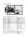
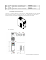
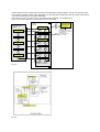
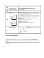
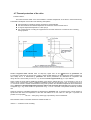
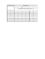
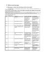
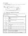
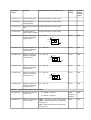
Power Electronics Company TWERD AFC150 User's manual CONTENTS SPECIFICATION OF AFC150 …............................................................................................. 3 1. Conditions of safe operations ......................................................................................5 2. Instalation of the frequency converter …......................................................................6 2.1.1. Safety rules …....................................................................................................6 3. The control panel …....................................................................................................11 4. Configuration of the frequency converter …...............................................................14 5. Th first start …............................................................................................................24 6. Failures and warnings …............................................................................................25 6.2.1. Manual deletings …..........................................................................................25 6.2.2. Digital input deletings …...................................................................................25 6.2.3. Remote RS link deletings ….............................................................................26 7. Sets of factory parameters ….....................................................................................26 8. PI Regulator …...........................................................................................................26 9. Configuration of RS485 …..........................................................................................28 10. Information from the manufacterer ….........................................................................31 Appendix ..........................................................................................................................32 Power Output Control system Voltage Uin Output voltage Frequency resolution Modulator Operation mode Switching frequency Rotation speed setting Analog inputs Control inputs/outputs Digital inputs Analog outputs Digital outputs Connectors Communication protocol Communication Transmission speed Application PI-regulator Special functions Protection Set of Predefined (Factory) Parameters Short-circuit protection Overcurrent protection Device thermal protection Motor thermal protection Supervision of communication through RS Control of analog inputs one-phase power : 230V -15% +10%, if ordered –other Voltage available 0 ... Uin [V] / 0,0 … 320Hz 0.01Hz SVPWM U/f linear / square-law scalar 4,8,16kHz Analog inputs, control panel, motopotentiometer, PI-regulator, communication unit RS485 and other possibilities. Resolution of 0.1 % for analog inputs or 0.1Hz / 1 rpm for the control panel i RS 2 analog inputs (AI0 I AI1): voltage mode 0(2) ... 10V, Rin ≥ 470kΩ; accuracy 0,5% 6 digital separated inputs 0/(15...24)V. Rin ≥ 8kΩ 1 output 0(4)....20mA – configuration with the help of parameters and switches, accuracy:0.5 % 2 relays (K1, K2) – breaking capacity: 250V/5A AC RS485 with optoisolation MODBUS RTU. Function 3 (Read Register); Function 6 (Write Register). 9600 or 19200 bit/s Remote control of unit operation and programming of all parameters of the frequency converter. Choice of referencing-unit signal source and feedback signal source, possibility of inverting polarity of an control error signal , SLEEP function and output erasing on STOP signal, limitation of an output value. There are 6 available set of predefined parameters: - Local: control from keyboard - Remote: control through digital or analog inputs - Local/Remote: choice between local and remote - PI: speed regulated by PI-regulator - Motopotentiometer: control with “increase/decrease” signals from digital inputs - Constant frequencies: operation with constant frequencies, switching through digital inputs Short-circuit on unit output. Instantaneous value 3.5 In;; effective value 2.5 In Radiator's heat sensor, 85oC I2t limit, motor heat sensor. Established permissible time of connection absence. Check of absence of “living null” in modes 2... 10V and 4... 20mA Table 0.2 - Specifications of frequency converters of the MFC710 series, depending on a type Constant-torque load Variable-torque load Overload 1.5 Overload 1.1 Type of frequency PN1 IN1 PN2 IN2 converter AFC150-0,37kW AFC150-0,55kW AFC150-0,75kW AFC150-1,1kW AFC150-1,5kW AFC150-2,2kW AFC150-3,0kW [kW] 0,37 0,55 0,75 1,1 1,5 2,2 3,0 [A] 2,2 3,0 4,0 5,5 7,0 9,5 14,0 [kW] 0,55 0,75 1,1 1,5 2,2 3,0 4,0 PN1 – nominal power at overload 1.5 In IN1 – nominal output current at overload 1.5 In PN2 – nominal power at overload 1.1 In (pumps, ventilators) IN2 – nominal output current at overload 1.1 In (pumps, ventilators) IP – overload current 60s every 10min [A] 3,0 4,0 5,5 7,0 9,5 14 19 Ip [A] 3,3 4,5 6,0 8,3 10,5 14,5 21 1. Conditions of safe operation 1.1 Warnings • • • After connecting converter to the supply network, internal circuit components (except In/Out clamps) are on the supply network potential. Touching them can cause an electric shock.. When you connect the converter to the supply network there is a dangerous voltage on clamps U, V, W, even when the motor does not work. After disconnecting the device from the supply network the dangerous voltage is still present for about 5 minutes. 1.2. Basic rules Don’t make any connections when the converter AFC150 is connected to the mains. Don’t connect mains voltage to output clamps U, V, W. Don’t measure the voltage endurance of any unit devices. To measure the cables insulation it is necessary to disconnect them from the converter. Don’t touch integrated circuits and any other parts on the converter's electronic board, as they can be damaged by electrostatic discharge. Don't connect any capacitors to motor wires intended for improvement of power factor Don't measure output voltage of converter using digital voltmeters 1.3 Operation list applied at first start-up of the system The operations applied at installation and the first start-up of the electric drive ✔ After unpacking the converter, it is necessary to check up visually presence of damages which could arise during transport. ✔ Check up the correspondence between the delivered frequency converter and the order - check up the ratings plate on the case. Delivery includes: • the frequency converter with the User's manual, • a ferrite ring or RFI filter - depending on the order. ✔ Check up the correspondence between conditions in which the converter will be used and conditions of an environment for which it is designed (section 1.4). ✔ Installation of the frequency converter should be made according to principles of safety and EMC rules, listed in section 2. ✔ Choose a configuration of the frequency converter and realize it according to sections 4 and 5. Environmental conditions Degree of pollution During design second degree of pollution has been assumed, at which there are normally only nonconducting pollution. However there is a probability of temporary conductivity caused by a condensation, when the converter doesn't work. In case the environment in which the frequency converter will work, contains pollution which can influence its safety, it is necessary to apply appropriate counteraction, using, for example, additional cases, air channels, filters etc. Climatic conditions Installation site from -10°C to +55°C1 During warehousing from -25°C to +55°C During transport from -25°C to +70°C Temperature Protective packing from 5% to 95% Relative humidity Air pressure 1 from 5% to 95% Max 95% Short-term, insignificant condensation on the external side of the converter case is permitted only when converter doesn't work. from 86 kPа to 106 kPа from 86 kPa to 106 kPa from 70 kPa tо 106 kPa For nominal load temperature 40oC was assumed, however for lower loads higher temperatures are acceptable. 2. Installation of the frequency converter 2.1. Connection of a power circuits The AFC150 converter is fed from the one-phase supply line 1x230V (AC, 50Hz). The application of a threewire shielded cable is recommended (L1, N and PE). In the fig. 2.1 the scheme of power circuits connections is presented. Diameters of wires and protection values should be selected depending on output current of the unit. Braking resistor Switch Overcurrent protection L1 L2 L3 PE Shielded cable recommended Br L1 U L2 V L3 W PE For rated power 5.5kW and above 3phase choke is recommended Fig. 2.1. P ~M PE MFC710 - Do not use any contactors between converter output and motor ! - Output voltage can be measured correctly only with an electromagnetic voltmeter ! 2.1.2Safety rules Equipotential connections The protection against indirect touching live parts consists of automatic switching off by special short-circuit protection (or differential-current protection) or voltage limitation to a level not exceeding acceptable values, in case of an insulation failure. The short circuit to ground at the frequency converter output can be not detected by short-circuit protection, devices due to DC link circuit. The protection against interpolar and ground short-circuit on the output of the converter is provided. However this protection is based on IGBT transistors blocking, what does not conform to the requirements of fire-prevention protection. Due to that, for safety of staff, it is necessary to make local equipotential connections. In the frequency converter there are provided appropriate terminals, properly marked, protected from corrosion to make equipotential connections. Protection Use of gG or aM fuses is allowed in the circuits, however taking into account necessity of protection of the rectifier bridge of the frequency converter, the best solution is gR or aR fuses. You can use overcurrent protection, but the response time of such devices is longer than properly chosen fuse. Frequency converter is protected from: drive overloading, motor overheating, under- and overvoltage in an DC link circuit of the converter, a short-circuit at the converter output (it protects converter only!!). Usage of differential-current protection due to electrical shock prevention can appear unfavorable, since it can trigger due to temporary or constant leakage current of the power drive system, working in normal conditions. In case of usage of the differential-current protection devices you may use only cut-out switches of a B type, due to different nature of a differential current. Disconnecting device In order to comply with EU directives, according to PN-EN 60204-1:2001, power drive, which consists of a frequency converter and electrical machine should be supplied with a device for disconnecting power supply. This device should be one of listed below: • separator (with or without fuses), category of usage AC-23B fulfilling the requirements EN 60947-3, • disconnector (with fuses or without), disconnecting a load circuit before opening main contacts, conforming the EN 60947-3 requirements, • tripper conforming the EN 60947-2 requirements. User is obliged to fulfil this requirement. Emergency stop In order to comply with EU directives and PN-EN 60204-1:2001 and for personnel safety and equipment, it is necessary to use an emergency stop switch, which has higher priority than other functions, irrespective of operating mode. The key STOP on operator panel cannot be treated as the switch of abnormal break, because it doesn't disconnect a frequency converter from power supply. User is obliged to fulfill this requirement. Casing The casing conforms to the requirements of a IP20 protection degree. The surface, on which the control panel is situated fulfills the requirements of a IP40 protection degree. The casing was designed in such a manner that it cannot be removed without usage of tools. Capacitors discharging In a DC link circuit of a frequency converter there is a capacitor battery with relatively high capacity. After turning off of a supply voltage in its clamps dangerous voltage is present for a certain time. It is necessary to wait for 5 minutes before making connections on clamps of power terminal strip of a frequency converter. The information about danger of such voltage is placed also on terminal strip cover. The AFC150 converter is fed from the one-phase supply line 1x230V. In the fig. 2.1 the scheme of power circuits connections is presented. Diameters of wires and the parameters of chokes should be selected depending on current of a load. 2.1. The frequency converter is supplied with appropriate resources, protected from corrosion, dedicated to make apropriate connections. Additional information about external connections can be found in section 2.1.1 under the “Equipotential connections” and in section 2.1.2. In order to comply with EU directives of electromagnetic compability (EMC) application of a four-wire shielded cable (three phases + earth wire) is recommended to fed the engine. Type of mains choke and protections is available at producer's representative. It is strogly recommended not to use any switches or contactors at the converter output that could disconnect system during the run. 2.2Connection of control circuits On fig. 2.2 user terminal block of AFC150 are presented. In the table 2.1. are the descriptions and functions of clamping rods showed in the fig. 2.2. AFC150 X2 AFC150 X1 Analog output Analog input Digital inputs +5V J25 K1 NO NC NO 1 2 3 4 5 6 7 8 9 10 11 12 13 14 15 16 NC COM COM B A AGND AO1 AGND AI1 AI2 +10V GND DI1 DI2 DI3 DI4 DI5 DI6 +24V J26 K2 1 2 3 4 5 6 7 8 9 10 11 12 13 14 15 16 X1: X1: X2: X2: RS485 1 2 3 4 5 6 1 2 3 4 5 6 Fig. 2.2 Tab. 2.1. terminal block – evaluation of inputs and outputs on the X1 block No Name Description X1-1 B Interface RS-485, line B Terminator/bias are connected with jumpers J25/J26 X 1-2 A Interface RS-485, line A The same X1-3 AGND Analog Ground Use only for connecting analog inputs/ outputs signals X1-4 Way Analog output X1-5 AGND Analog Ground X1-6 AI0 Analog input 1 Input impedance 500 Ohm X1-7 AI1 Analog input 2 The same X1-8 +10V Supply of external systems, i.e. potentiometer of Load capacity of the source: 100mA referencing-unit X1-9 GND General mass X1WeC1 Digital input 1 Input impedance 7KOhm 10 X1WeC2 Digital input 2 Input impedance 7KOhm 11 X1WeC3 Digital input 3 Input impedance 7KOhm 12 X1WeC4 Digital input 4 Input impedance 7KOhm 13 X1WeC5 Digital input 5 Input impedance 7KOhm 14 X1WeC6 Digital input 6 Input impedance 7KOhm 15 X1+24V Supply odf external systems Load capacity of the source: 200 mA 16 Tab.2.2 terminal block – evaluation of inputs and outputs on the X2 block X2-1 K1 (NO) Relay input K1, contact N.O. (normal open) X2-2 X2-3 K1 (COM) K1 (NC) Relay input K1, contact COM (common) Relay input K1, contact N.C. (normal closed) Load capacity of contacts 5A/250VAC Load capacity of contacts 5A/250VAC Load capacity of contacts 5A/250VAC X2-4 K2 (NO) Relay input K2, contact NO (normal open) X2-5 K2 (COM) K2 (NC) Relay input K2, contact COM (common) X2-6 Relay input K2, contact N.C. (normal closed) Load capacity of contacts 5A/250VAC Load capacity of contacts 5A/250VAC Load capacity of contacts 5A/250VAC 2.3. Assembly (mechanical) drawings In the fig 2.3. an overall view of AFC150 is showed. On the fig 2.4. a drawing with detailed size is being presented. During the assembly it is essential to remember to leave a free space around the device to insure the right air circulation (10 cm from above and from the bottom side and 3 cm on both sides of the device) 2.3. View of AFC15 Fig.2.5. Overal dimensions and wiring draft Table 2.3. Sizes of AFC150 Type Size [mm] a A AFC150/0,37kW AFC150/0,55kW 151 168 AFC150/0,75kW AFC150/1,1kW AFC150/1,5kW 175 187 AFC150/2,2kW AFC150/3,0kW kg B c C 70 60 133 73 74 166 Fig.2.5. Required free space 3. The control panel On fig. 3.1 is the control panel with all functions presented. D1 5,0 D2 8,0 ᶲ1 10,5 ᶲ2 6,0 0,8 0,8 1,0 1,0 1,0 1,0 1,2 Control panel serves for constant review of the process parameters (rotational speed, current), the operating mode control (START / STOP, change of the referencing unit, cancelling fault message) and also for viewing and changing of converter's parameters. In the panel LED display. After switching on the converter to mains, the control panel is switched on in the Base Mode. On fig. 3.2 the main sequence of control panel service is presented. PARAMETERS MODE PAR. GROUP 0 ↔ PAR. GROUP 1 ↔ PAR. GROUP 2 ↔ PAR. GROUP 3 ↔ PAR. GROUP 4 ↔ BASIC MODE ↑ F REFERENCE [Hz] ↔ Fig 3.3 * VOLTAGE [V] ↔ * TEMPERATURE ↔ * REVOLUTIONS [RPM] ↔ * FREQUENCY. [Hz] ↔ Fig. 3.2. * CURRENT [A] ↔ ↓ * QUICKIE PREVIEW * CHANGING OF REFERENCE VALUE CHANGING OF FREQUENCY BY PANEL IS POSIBBLE ONLY WHEN REFERENCE IS SELECTED ON ”KEY” As attachment for fig. 3.2 see fig 3.4. pictures of displayer panel in the quick search mode Fig 3.4. Changing the value of parameters fig. 3.5. Fig 3.5 4. Configuration of the frequency converter Main possibilities of converter control – referencing output frequency (rotation rate) and configuration of control with a START / STOP signal - are described below with additional information about configuration of output relays of a converter. More detailed information is in „parameter list” – (Appendix). The control possibilities of the converter arise from the analysis of a structure of the control system - fig. 4.2/4.3. In control system of the converter AFC150 there is a philosophy of 2 independent „control places” A and B, that allows to change whole structure of the converter control (sources of START and STOP signals and sources of frequency for electric drive operation) by changing only one parameter. In fig. 4.1 there is simple diagram and in fig. 4.2 and 4.3 there are developed diagrams of the converter control. A controlol mode SOURCE OF CONTROL SIGNALS - Panel - Analog input - Digital input - RS - PI - others Par. 2.2 (REFERENCE) Par. 2.4 (START) SWITCH OF CONTRL MODE - Locks - Eliminations bands - Constant frequencies - RS B control mode START / STOP Par. 2.3 (REFERENCE) Par. 2.5 (START) Par. 2.1 Fig. 4.1. Frequency In.A1 In.A0 REGISTER 2001 MODBUS RS Reference [Hz] Parameters 2.20, 2.21, 2.22, 2.23 MOTOPOTENTIOMETER Parameters 2.60... 2.71 PI regulator Configuration of Analog Input A1. Configuration of Analog Input A0 PANEL Hz (U/f) or rpm (vector) Hz (U/f) lub rpm (vector) 1 0 0 Selector B par. 2.3 Convertion 2.11, 2.12 0.0 100.0 Convertion % → Hz Convertion 2.11, 2.12 0.0 100. 0 W3 - Par. 2.32 W2 - Par. 2.31 Enaybling of F constant W1 - Par. 2.30 ≠Key =Key A/B par. 2.1 ≠Key =Key 1 F const A/B Not F par. 2.1 Constant 0 Const frequency selection: W1 W2 W3 Input --------------------------------------------0 0 0 Nie F stała 1 0 0 F const 1 (par. 2.33) 0 1 0 F const 2 (par. 2.34) 1 1 0 F const 3 (par. 2.35) 0 0 1 F const 4 (par. 2.36) 1 0 1 F const 5 (par. 2.37) 0 1 1 F const 6 (par. 2.38) 1 1 1 F const 7 (par. 2.39) F min F max F min F max A/B par. 2.1 - Enable RS (par 4.7 not equal 0) - BIT5 2000 register (MODBUS) = 1 RS frequency control only when : RS direct Frequency control mode OFF AFC150 Structure of frequency selector Convertion % → Hz Par. 0.46 Par.0.45 Selector A par. 2.2 Enable RS (PCH.40) par. 4.7 In.A0 In.A1 Not use Out.PID 5: Motop. 6: RS 1: 2: 3: 4: 0: Key. 0: Key. 1: In.A0 2: In.A1 3: Not use 4: Out.PID 5: Motop. 6: RS Configuration of Sel A0 Parametrs 2.43, 2.46 (skala i offset) Configurations of Sel A1 Parametry 2.44, 2.47 (skala i offset) F Zad. Cuttings of eliminations bands. Parameters: 1.90, 1.91, 1.92, 1.93, 1.94, 1.95 F F Zad. Determinate direction of the rotation – par. 1.65 Parametry 2.13, 2.14 F Minimal Frequency or STOP Frequency Signal locked when frequency below minimal freq(par. 2.13) and par. 2.14 = 1 Actual reference frequency DI3 DI2 DI1 REMORE START Register 2000 MODBUS Bit 15 START / STOP RS Variants: 0 = Start DI1, DI2 1 = DI1 Start right, DI2 Start left 2 = Impulse DI1 Start, impulse DI2 Stop, Direction = 0 3 = the same, p.2. Plus DI3 - direction 4 = DI1 Start, Directiion = 0 1 0 0 PCH.33 PCH.30 ERASE OF LOCAL PCH.31 START Par. 2.xx LOCAL START LOCAL REVERSE (PCH.34) Configuration of remote parameter 2.8 start PANEL Enable RS (PCH.40) par. 4.7 START RS (PCH.32) START / REVERSE B Par. 2.5 Paramete r 2.7 0 PCH.x Paramete r 2.6 0 PCH.x START / REVERSE A Par. 2.4 1 0 1 0 A/B (PCH.39) par. 2.1 Defines change of a sign of ref.-unit and change of a direction of rotation. (See the block diagram of frequencies selector) REVERSE (PCH.38) - Enable RS (PCH.40) = 1 (about value PCH.40 determine par. 4.7) - BIT6 of register 2000 (MODBUS) = 1 Constraint START / STOP by means of RS only when: No RS constraint AFC150 Structure of control START / STOP 1 = Control allows on start of the electric drive. START (PCH.37) - If fault has done - Electric drive operates low F STOP (par. 2.13 and 2.14) - External blocking of operates (par. 2.111) - External operation permitted to operate (par.210) - Blocking with RS (Bits 14, 13, 12 of register 2000 MODBUS, when par. 2.60 allow operation RS) - Blocking from control of pump group. BLOCKING 1 = Electric drive is blocked BLOCKING (PCH.73) 1 = Electric drive operates OPERATION (PCH.61) 4.1 Control from the control panel In order to control the electric drive from the control panel it is necessary to: choose „ control place ” A or B with the help of parameter 2.1 establish parameter 2.2 (for A) or 2.3 (for B) to in position „> 0 Keys ” establish parameter 2.4 (for A) or 2.5 (for B) to in position „> 1 Keys ” make sure, that the constant speed mode isn't chosen: Par. 2.30, 2.31 and 2.32 should be established in position „> 0 Switch off ” Control through terminal connections To have an opportunity of control of the electric drive through terminal connections (e.g. START / STOP through digital inputs and regulation of rotation speed with the help of a potentiometer) it is necessary: To choose „ control place ” A or B with the help of parameter 2.1 To set up value of parameter 2.2 (for A) or 2.3 (for B) in position: – „> 1 We.A0 ” for an analog input 0 – ,,> 2 We.A1 ” for an analog input 1 To set up value of parameter 2.4 (for A) or 2.5 (for B) in position „> 0 We.Cyf To set up value of parameter 2.6 (for A) or 2.7 (for B) in position 0 (switch on of the control of analog inputs directions) To be sure that the choice of a mode of constant speed is not made: values of parameters 2.30, 2.31 i 2.32 should be set up „> 0 Wylacz” To set up parameter 2.8" Remote start ”. It defines functions of control digital inputs as at the tab. 4.1 Table 4.1 - possible configuration variants of remote start (START) Value of par. 2.8 „Remote start” 0 1 2 Notation Function We.C1 = START/STOP Voltage feeding to digital input 1 results in start and voltage removal D stopping of the electric drive. The condition of a digital input 2 defines change of a direction of drive rotation We.C2 = DIRECTION We.C1 = START to the RIGHT Voltage feeding to digital input 1 results in a drive start. Voltage feeding to digital input 2 results to a drive start in opposite direction. We.C2 = START to the LIFT We.C1 =PULSE START We.C2 = PULSE STOP Direction of rotation depends only on sign of referencing-unit signal. We.C1 =PULSE START 3 We.C2 = PULSE STOP We.C3 = DIRECTION 4 Voltage feeding to digital input 1 results in start and voltage removal We.C1 = START/STOP stopping of the electric drive. Direction of rotation is depends only on sign of referencing-unit signal.. Display in mode “control state” looks as in the fig. 4.4 – referencing-unit from analog input and START from digital input. Regulation of output frequency of converter and rotation speed of drive is carried out through selected analog input (e.g. with a help of potentiometer). 4.2. Work with constant speeds The system can work with one of seven constant speeds. The choice of constant speed is made by digital inputs determined by parameters 2.30, 2.31 and 2.32 - an example in table 4.2. Sizes of constant speeds are defined by parameters: par. 2.33 – constant speed number 1 [Hz] par. 2.34 – constant speed number 2 [Hz] par. 2.35 – constant speed number 3 [Hz] par. 2.36 – constant speed number 4 [Hz] par. 2.37 – constant speed number 5 [Hz] par. 2.38 – constant speed number 6 [Hz] par. 2.39 – constant speed number 7 [Hz] Table 4.2 – suggested configuration of constant speed control Parameters Example Notation 2.30 W1 >3 We.C3 Signal of constant speed selection W1 comes from digital input 3 (W1 = DI3) 2.31 W2 >4 We.C4 Signal of constant speed selection W2 comes from digital input 4 (W2 = DI4) 2.32 W3 >0 SWITCH OFF. W3 = 0 !!! ATTENTION!!! - see structural circuit of frequency referencing-unit - section 4.2.1 As a result of choice of such parameter configuration it is possible to choice between 3 available constants through digital inputs 3 and 4: State DI3 State DI4 Effect Electric drive does not operate with constant speed. At this moment another referencingunit is operating. (See structural circuit of frequency referencing-unit - section 4.2.1) 0 0 1 0 Constant speed no. 1 ( Value as Par. 2.33) 0 1 Constant speed no. 2 ( Value as Par. 2.34) 1 1 Constant speed no. 3 ( Value as Par. 2.35) CONTROL STATE display when constant speed referencing-unit is active looks like it is shown on fig. 4.5 – Referencing-unit: constant frequency (speed), START through digital input. 4.2.1. A motopotentimeter Motopotentiometer is a simple “increase-reduce” device for speed control of drive rotation with help of two buttons. An example way of connecting “increase-reduce” buttons to the frequency converter is shown on fig. 4.6a. Fig. 4.6b. Illustrates action of the device In order to set the output frequency of the converter with help of a motor-potentiometer par. 2.2 (for control A) or 2.3 (for control B) must be set on value "MotPot" (mP). Attention: Fig. 4.6a corresponds to a situation when par. 2.20 = “DI3” and par. 2.21 = “DI4”. There are four available modes of motopotentiometer operation: 0, 1, 2 and 3. Modes 0, 1 and 2 should be used only when current referencing-unit (par 2.2/par. 2.3) is set on “MotPot”. Mode 3 can be used regardless of setting of current referencing-unit. Stopping the converter In mode 0 will cause reset of motopotentiometer settings. In mode 1 settings of motopotentiometer will be stored and there is no possibility of changing it while the drive is stopped. In mode 2 settings of current referencing-unit are traced by motopotentiometer so switching from current referencing-unit to motopotentiometer's referencing is made very easily. In mode 3 configuration of motopotentiometer is stored and there is possibility of changing it while the drive is stopped. 4.3.Analog inputs Frequency converter has two analog inputs (We.А0, In,А1 and We.А2), which cooperate in voltage mode 0-10V .It is possible to connect directly a potentiometer or a voltage (current) source to analog inputs - see fig. xxx Table xxx compares the parameters responsible for a configuration of the analog inputs. By analogy to digital inputs, analog inputs have no parameters which define their function in the system. Inputs are selected by control configuration parameters to perform certain actions. Xxx Table 4.3 - parameters which define a configuration of analog inputs Paramet er Function Description 2.40 Configuration range of We.A0 Choice of range for input value 0...10V, 2...10V, 10...0V (inversion), 10...2V. 2.41 Configuration range of We.A1 0-10V, 10-0V, 2-10V, 10-2V (voltage mode) 2.42 Configuration range of We.A2 0-10V, 10-0V, 2-10V, 10-2V (voltage mode) 2.49 Constant of time lowpass filter We.A2 for Paramet er 2.50 Function Description Constant of time lowpass filter We.A1 for As par.2.49 0.40 Value We.A0 [%] READ ONLY. Value We.A0 in [%]. e.g. for corresponds par. 0.40=50.0 % range 0... 10V voltage 5V 0.41 Value We.A1 [%] READ ONLY Value We.A1 in [%]. e.g. for corresponds par. 0.41 =50.0% range 0... 10V voltage 5V 3.23 In operating modes 2... 10V, 10... 2V it is possible to define behavior of the Reaction to signal absence electric drive when value of voltage falls below 1V or value of a current falls at the Analog Input below 2mA. (See. Appendix C - par. 3.23). In structure of the electric drive Analog Referencing-units are also provided. Analog referencing-units are strictly connected to Analog Inputs, from which they differ, that they have parameters carrying the information on value of their offset and scale. Usually analog referencing-units are used only as inputs for the PI-regulator. As control signals in any point of the structural diagram of control (e.g. fig. 4.9b). In the table 4.4 there are parameters which define a configuration of Analog Referencing-units and dependence of value Ref.A from AI. Table 4.4 – Analog Referencing-units Paramete r Function Description 2.43 Ref.A0 scale Value in [%] : -500.0 ... 500.0 % 2.44 Ref.A1 scale Value in [%] : -500.0 ... 500.0 % 2.45 Ref.A2 scale Value in [%] : -500.0 ... 500.0 % 2.46 Ref.A0 offset Value in [%] : -500.0 ... 500.0 % 2.47 Ref.A0 offset Value in [%] : -500.0 ... 500.0 % 2.48 Ref.A0 offset Value in [%] : -500.0 ... 500.0 % 0.45 READ ONLY. Value Ref.А0 in [%]. Ref.A0 = (par. 2.46 + par. 2.43 * We.A0 / 100.0%) Ref.A0 value [%] E.g: if par. 2.46 = 20.0%, par. 2.43 = 50.% and Ref.A0 = 30.0% Ref.A0 = 20.0% + 50.0% * 30.0% / 100.0% = 35.0% 0.46 Ref.A1 value [%] READ ONLY. Value Ref.A1 in [%]. Ref.A1 = (par. 2.47 + par. 2.44 * AI1 / 100.0%) 4.4.Analog outputs Table 4.5 presents parameters which concern configuration of analog output WyA0. It operates in a current mode 0-20mA (4-20mA). Table 4.5 – Parameters which define configuration of analog outputs Paramete r Function Description Wy.A1 0...100.0% READ ONLY Value of analog output 1 Wy.А1 = Absolute value (signal * scale Wy.A1 / 1000) 2.80 Choice of signal for Wy.A1 Details in Appendix C 2.82 Configuration of range Wy.A1 0...20mA, 20...0mA, 4...20mA, 20...4mA (current mode ) Out.А1 scale 0 ... 500.0 %. Typically 100.0 % Examples: For a configuration 0-10V signal value 1000 at a scale established on 100.0 % corresponds to voltage value 10V. 0.43 10V 1000 Signal 2.84 Scale = 100% Mode 0...10V 0 OutA 0V 10V 500 Signal 0 Scale = 200% Mode 2...10V OutA For a scale established on 50.0 % to receive 10V of output voltage the signal value should be 2000. Similarly for a scale established on 200.0 % to receive 10V of output voltage the signal value should be 500. Value of a signal corresponds to value of the selected size without a decimal point, e.g.: 12.5 % = 125 2.43 A = 243 375 В = 375 e.g., if signal (value of current) is 11.7 A it corresponds to 117 number. In this case: voltage = scale * signal / 1000 voltage = 100.0% * 117 /1000 = 11.7 %(0...10V) = 1.17 V 2V Constant of time for the lowpass filter of AO1 Filter of analog output AO1 – see Appendix C for more details 2.86 Formation of U/f characteristic In modes of scalar control U/f there is an possibility of influence on type of the characteristic. In modes of vector control (Vector 1 and Vector 2) parameters of U/f characteristic formation are not relevant. The main parameter which influences on form of the electric drive characteristic is par. 1.20 "Operating mode”: Mode U/f linear. It is used if there exists a constant moment of loading which does not depend on speed (see fig. 4.11). Mode U/f square-law. It is used if the moment of loading grows under the square-law from speed (e.g. the electric drive of the fan). Use of square-law characteristic U/f cause reduction of noise and decrease of losses in the motor (see fig. 4.11). Fig. 4.5 - Linear and square-law characteristic(a), formation of U/f characteristic (b) 4.6.Elimination of frequencies With purpose of elimination of undesirable output frequencies which can result in the resonant phenomena of the drive, it is possible to determine 3 ranges called "ranges of elimination”. Their options can be set up by parameters: Par. 1.90 - bottom frequency of elimination range 1 [Hz] Par. 1.91 - top frequency of elimination range 1 [Hz] Par. 1.92 - bottom frequency of elimination range 2 [Hz] Par. 1.93 - top frequency of elimination range 2 [Hz] Par. 1.94 - bottom frequency of elimination range 3 [Hz] Par. 1.95 - top frequency of elimination range 3 [Hz] Referencing-unit of the electric drive will "bypass" frequencies which are chosen with the help of the parameters above mentioned. Fig. 4.6 shows influence of range elimination procedure on output frequency of referencing-unit. 4.6.Blocking a direction of drive rotation There is a possibility of partial blocking of the electric drive with permission of operation only in one direction. In this case irrespective of control signals the frequency converter will rotate the drive only in one direction. Parameter 1.65 allows to define this option: "Reverser" - operation in two directions (option relative) "To the left" - operation in one direction "To the right" - operation in one direction 4.7.Thermal protection of the drive Protection limit I2t The built-in thermal model of the drive enables to calculate temperature of the drive in the theoretical way. The Model is developed on the basis of the following assumptions: the temperature of windings changes according to exponential law, the drive achieves the maximal temperature for continuous work at a rated current change of temperature depends on a ratio (I/In) 2, the constant of time of cooling for stopped drive is four times more than a constant of time of heating during operation Relative long-term motor current value for frequency higher then 25 Hz is determined by parameter 3.3. For frequency lower then 25 Hz long-term current is lower (smaller efficiency of the cooling fan which is placed on a drive shaft) and it is determined by parameter 3.4. These parameters are determined in comparison with rating value of a drive current (for 100.0 % = In). Thus the area of long-term work (fig. 4.17a) is defined. When cooling the motor without additional ventilation (only with the internal fan) par. 3.4 is necessary to set up on value of 35 % of rated motor current. If additional ventilation of the drive is used value of par. 3.4 can be set up to 75 %. If the motor current is outside of defined area of long-term operation the calculated temperature will increase above 100 %. When the calculated temperature achieves value of 105 % electric drive will stop (the message of failure will appear (fig. 4.18)). Such situation is represented on fig. 4.17c for a increase in temperature marked by a dotted line. Speed of increase in calculated temperature is determined by parameter 3.5 - a constant of time of motor heating. It equals time after which the temperature of the drive will achieve 63 % from value of a final gain. In practice it is possible to accept option: Par. 3.5 = 120*t6 [min], where t6 [s] is provided by motor manufacterer Demonstration values of constants of time are resulted in table 4.7. Table 4.7 – Constants of time of heating Nominal power of the motor Pn [кW] Quantity of poles 2 4 6 Constant of time of motor heating [min] (par. 3.5) 2.2 11 17 24 3.0 12 18 26 4.0 13 19 29 5.5 15 21 29 7.5 16 23 31 11 19 26 34 15 20 29 39 5. The first start Before first start of the converter AFC150 it is necessary to check section 4 “Configuration of frequency converter”.The structural circuit of control AFC150 and Appendix – table of parameters of AFC150 are also very important Main options: 1. 2. Description nominal parameters of the drive “control place” A or B See section 4 “Switch off” = Control A “Wy.C1” = Choice A/B with help of digital input 1 ... “Wy.C6” = Choice A/B with help of digital input 6 “Switch on” = Control B 3. Source of signal START/STOP (local from control panel, remote from digital inputs, remote from RS or others) parameter 2.4 “START A” - source of signal START for control A parameter 2.5 “START B” - source of signal START for control B 4. method of referencing frequency or rotation speed of the motor (local from control panel, remote from analog input, through link RS, motopotentiometer, from PIDregulator or others) parameter 2.2 “START A” - source of referencing-unit for control A parameter 2.3 “START B” - source of referencing-unit for control B 6. Failures and warnings 6.1 Messages on failures and warnings on the control panel The luminescence of a red light-emitting diode LED (with a “FAULT” description) and messages (fig. 6.1) signals about failure state. Thus the frequency converter passes to STOP mode. To make the next START it is necessary to deal with a failure and to erase the message of failure. In case of some failures the automatic restart (deleting of the message) is possible after disappearance of the failure reason. Warning state is signaled by the appropriate message on the display without stopping the frequency converter, and also by a blinking red light-emitting diode LED (fig. 6.2). Warning is automatically erased after a drive stop. In both cases functioning of a control panel is not blocked. It is possible to look through and change all parameters of the converter without obstructions. Tab. 6.1. Failures codes Code Displayed name description Possible cause/ reason Counteraction E.1 Radiator temperature higher The air course through Check efficiency of then 85ОC the converter is ventilation (efficiency complicated, unit of the ventilating fan overload, to high and pollution of a environment radiator) temperature E.3 High voltage in circuit DC Too high voltage in the Test the mains circuit, intensive Increase a time of braking of the drive braking Par 1.31 E.4 Low voltage in circuit DC Low voltage in circuit, Check connecting absence of one phase cables and a level of a of a supply voltage feeding voltage E.5 Short circuit on output of the Short circuit in the Disconnect the drive converter or failure of power drive or in the wires and test presence of a module feeding the drive short circuit, if present call service to repair drives, and if is not present test isolation of wires and windings of the drive E.6 The current of the drive is to high Too high intensity of acceleration, a sudden change of drive loading Overheating of the motor or operation with high loading at small speeds E.7 Overheating of the drive E.8 Damage of the analog input At input option with „living zero” (2-10V or 4-20mA) value of a signal is lower than 1V E. 13 Temperature of radiator is lower than 10ºC Temperature of converter's environment is to low. E.21 The signal of external failure is active E.27 Waiting time on a signal from RS is exceeded Failure of a cable, parameters of the transmission are incorrectly set up Increase acceleration time of the drive Check loading of the motor (current of the motor); check parameters of thermal drive model Check a configuration of analog inputs, test system of connection (damage of a cable, etc.) Check efficiency of heating Check a signal at digital input which is chosen as an external failure Check external connections and validity of RS parameters 6.2 Deleting failure message. Automatic restarts. 6.2.6 Manual deleting To delete the failure message Push for at least 2 seconds 6.2.6 Deleting through a digital input of the converter The parameter 3.70 allows to choose a digital input which will serve for deleting message of failure. 6.2.7Remote deleting through RS link If parameter 4.7 allows to operate with RS control mode, sequence of 2 next records in the register 2000 (MODBUS) deletes failure message. The detailed description of separate bits and methods of deleting can be found in the description of the register 2000. 6.3. Failure log Parameters 3.80...3.111 form the Failures Log allows to display a history of last 16 failures. Each record in the failure log consists of two parameters. First informs about failure code , and second - about time of its occurrence. Parameters 3.80 and 3.81 are the newest records of failure, and parameters 3.110 and 3.111 are the oldest records of failure. In a time of one hour of the converter operation the same failure can take place many times. In order to prevent overflow of the failure log, only the quantity of failures which occurred in last operating hour is increased. Thanks to this the real quantity of failures which the failure log can remember increases. 7. Sets of factory parameters There is 1 set of factory parameters (table 7.1) intended for loading standard, most used control programs. It is to find in parameter table attached. Frequently in the beginning it is better to load one of the instanced standard sets of parameters, than manually change a lot of parameters of the frequency converter. To carry out drive identification (see section 4.4 ). 8. PI – regulator Frequency converter has a PI- regulator (Proportional – Integral). The regulator can be used for stabilization of any parameters at fixed level (fig. 8.1). 8.1. Turning on and a configuration of the PI-regulator To enable PI – regulator as a source of referenced frequency it is necessary to set up par. 2.2 (for control A) or 2.3 (for control B) on value “Wy.PI” (fig. 8.2). Table 8.1 - Control and information parameters of the PID-REGULATOR Parameter 2.60 Name Description Ref.PI choice Source of ref.-unit for PI-regulator. It serves for setting process referenced value. Possible values: 0-Keyboard- referencing PI from control board 1- Ref.A0 2- Ref.A1 RS –analog referencing-units from communication module RS232/485 (Modbus) 2.61 InPI choice Signal source of feedback od PI-regulator. 0-Ref.A0 1-Ref.A1 2.62 Error inversion Error inversion (difference between tasked value and feedback signal) NO / YES 2.63 P amplification (Kp) Amplification of proportional component of PI-regulator. The bigger amplification, the faster reaction to speed error 2.64 I Const (Ki) 0.01 ... 320.00s 2.66 Max OutPI Max value which output signal of PID-regulator can achieve (restriction of saturation) 0.0 .... 3000.0 % 2.67 Min OutPI Min value which output signal of PID-regulator can achieve (restriction of saturation) 0.0 .... 3000.0 % 2.68 PI reset 0.30 RefPI Value of current PI referencing-unit. READ ONLY. 0.31 InPI Current value of PI-regulator input. READ ONLY 0.32 PI error Value of current regulator error par 0.32 = par 0.30 – par 0.31 READ ONLY Parameter 0.33 Name OutPI Description Current value of PI-regulator output. READ ONLY 9.Control of the frequency converter by means of connection RS Frequency converter AFC150 is equipped with RS485 communication link. It enables to control work of device with help of a computer or an external controller. The basic characteristics and possibilities of the RS link of the frequency converter: ● operation with speed 9600 or 19200 bits per second, ● a format of a character: 8 data bits, lack of parity control, 2 stop bits, ● transfer protocol: MODBUS mode RTU, ● check of transfer validity with use of CRC sum, ● unit number (converter) set up with help of parameter (typically 12), ● support of MODBUS commands: command 3 - “read the register” - allows to read individual registers from the converter. Command 6 - “register write” - write to individual register in the converter, ● possibility of reading of an operating mode, control start/stop, reading and writing of referencing-units, ● possibility of reading and writing of all parameters of the converter just as by means of a control panel, All operations are based on two basic commands of MODBUS RTU protocol - 3 and 6 which are described in publications concerning МODBUS. 9.1. Parameters which concern communication through RS Table 13.1 - Parameters which refer to communication Paramete r Description 2.2 Referencing-unit A - it is possible to set up a source "RS" 2.3 Referencing-unit B - it is possible to set up a source "RS" 2.4 Start A - it is possible to set up a source "RS" 2.5 Start B - it is possible to set up a source "RS" 4.7 RS permission – it is possible to enable permanent permission to control from RS, disable permanent permission or, for example, set enabling/disabling RS permission from a digital input. The permission concerns referencing frequency through RS, RS PID referencing-unit, and a START / STOP/BLOCKING signal from RS (see table 13.2 - registers 2000, 2001 and 2002). 4.8 RS speed - possible options is 1200, 2400, 9600 or 19200 bits per second. 4.9 Number of device (converter) in MODBUS protocol (possibility of connecting several converters through one communication channel RS 485). CAUTION: If control RS blocked (par. 4.7), and parameters 2.2, 2.3, 2.4 or 2.5 define control as "RS" in this case the frequency converter remains in STOP mode or the referencing-unit of frequency will assume value 0. 9.2. Map of registers accessible through RS link All registers are 16-bit numbers. Addresses which are omitted in the table are not supported. Table 13.2 - Registers The address of the registers (decimal) Description (meaning) Mode REGISTERS OF OPERATING MODES 2000 The register RS CONTROL. The data is valuable only when the parameter 4.7 (RS permission) allows control of the device with RS. Bits meaning: bits 0 - not used bits 1 - the sequence 0 → 1 → 0 erases the message on failure bits 2,3 - not used Read / write bits 4 - 1 = force referencing PI from RS (the register 2002) bits 5 - 1 = force referencing frequency from RS (the register 2001) bits 6 - 1 = force START/STOP Control from RS bits 7,8,9,10,11 - not used bits 12 - 1 = BLOCKING of OPERATION shut down according to Parameter bits 13 - 1 = BLOCKING of OPERATION shut down RAMP bits 14 - 1 = BLOCKING of OPERATION shut down RUN OUT bits 15 - 1 = START 0 = STOP Bits 4,5,6 allow to force control of the drive through communication channel RS even if referencing-units or source of START / STOP signal is set up on value which differs from RS. If, for example, the referencing-units A is set up on value "RS" , to set frequency with RS, there is no necessity to set up bit 5. Forcing of control with RS by means of bits 4,5,6 results in switching off a source of the control established with parameters. Bits 12,13,14 block operation of the drive irrespective of the established type of control (also when, for example, there is control through RS and bits 15 = 1). The RS frequency referencing-unit operates only if the parameter 4,7 (RS permission) allows operation with RS. Resolution 0,1Hz (see. CAUTION), a range - 5000....5000. 2001 e.g. 250 = 25.0 Hz clockwise rotation The last value written down in this register cab be read. Read / write e.g.-122 = 12.2 Hz anti-clockwise rotation CAUTION. For a mode of vector control (the Vector 1 and Vector2) value is in rotations per one minute (rpm) instead of in Hz. 2002 The referencing-unit of the PID-regulator operates only if the parameter 4.7 (RS permission) allows operation with RS. Resolution 0,1 %, a range 0....1000. e.g. 445 = 44,5 % 2004 STATE OF CONTROL The register which informs from where current START/STOP signal and current frequency referencing-unit is coming. bits 0 - 1 = control A active bits 1 - 1 = control B active bits 2 - 1 = the referencing-unit from an analog input 0 bits 3 - 1 = the referencing-unit from an analog input 1 bits 4 - 1 = the referencing-unit from an analog input 2 bits 5 - 1 = the referencing-unit from a motor-potentiometer bits 6 - 1 = the referencing-unit from an output of the PID-regulator bits 7 - 1 = the referencing-unit from a control panel bits 8 - 1 = the referencing-unit with another PCH (advanced) bits 9 - 1 = START / STOP from digital inputs (remote) bits 10 - 1 = START / STOP from a control panel (local) bits 11 - 1 = START / STOP with another PCH (advanced) bits 12 - 1 = START / STOP set through RS connection bits 13 - 1 = the referencing-unit of frequency from communication channel RS bits 14 - 1 = active frequency is CONSTANT (f c) its 15 - 1 = the emergency referencing-unit is switched on (can be connected to other bits determining a source of the referencing-unit) 2005 Not used 2006 OPERATION STATE Value of this register serves for identification of the device's state: bits 0 - 1 = the drive operates bits 1 - 1 = one of referencing-units of a control panel (frequency, the PID-regulator or the user's referencing-unit) is switched on bits 2 - 1 = device is blocked bits 3 - 1 = ready to restart (failure message was erased, but reason has not disappeared) bits 4,5,6 - number of automatic restart/number of a stage of identification bits 7 - CRC error in EEPROM Read / write Read only Read only Read only bits 8,9,10,11,12 - a failure code or warning (0 - absence of failure) bits 13 - value of a failure code: 0 = failure, 1 – warning) bits 14 - a direction of operation (0 = to the right, 1 = to the left). bits 15 - 1 = identification (it is started by par. 1.10) THE REGISTERS CONNECTED TO PARAMETERS 40xxx Parameters from group 0. They are analogous with parameters on the control panel, e.g. the register 40003 corresponds to parameter 0.3 41xxx Parameters from group 1. They are similar with parameters on the control panel, e.g. the register 41020 corresponds to parameter 1.20. CAUTION: Changes of parameters are subjected to the same rules, as in case of Read / write operating from a control panel. There can be necessary to disable blocking of parameters change (parameter 4.1 = the register 44001) or entering of the corresponding code of access (parameter 4.2 = the register 44002). Some parameters of the device can be changed only in a case when it does not operate. Details: section 3.2 and following. 42xxx Parameters from group 2. They are similar with parameters on the control panel, e.g. the register 42001 corresponds to parameter 2.1. Read only Read / write CAUTION: the same as item 41xxx. 43xxx Parameters from group 3. CAUTION: the same as item 41xxx Read / write 44xxx Parameters from group 4. CAUTION: the same as item 41xxx Read / write 45xxx Parameters from group 5. CAUTION: the same as item 41xxx Read / write 46xxx Parameters from group 6. CAUTION: the same as item 41xxx Read / write 9.3. Handling of connection errors If connection errors appear or if the command with Improper parameter is sent, response of the device is described by MODBUS standard. Possible return error codes are: 1 = unknown command - when the command other than 3 or 6 is sent, 2 = wrong address - the address of the register is not supported by the electric drive (there is no such register), 3 = wrong value - command 6 tried to send value which is out of range of specified register In case of wrong transfer (e.g. CRC error) device does not send answers to commands. 10. Information from the manufacturer Help from PWC "TWERD” The Manufacturer provides the full help during guarantee and postguarantee service, updates of software and equipment. Periodic service In case of installation and use of the converter according to its specification, there is no necessity of its frequent periodic service. It is necessary to pay attention to cleanliness of a radiator and the fan. Radiator A plenty of a dirt which covers a radiator at operation worsens removing heat from device and can trigger protection against an overheat of the converter. Cleaning of a radiator can be made by means of pure and dry air under pressure using in addition a vacuum cleaner for gathering a dirt. Fan In case of strengthening noise at fan operation and reduction of its productivity, it is necessary to replace the fan. To replace the fan it is necessary to disconnect a cable feeding the fan, and to unscrew the fan. New fan should be ordered in TWERD. Appendix – Table of AFC150 frequency converter's parameters Numbers of parameters which are instanced in the appendix are numbers presented on the display of the control panel. In case of reading/writing by means of RS connection, each parameter is read/written with the help of specified register. For example the register 42002 corresponds to parameter 2.2 there, the register 44030 corresponds to parameter 4.30, etc. Parameters of GROUP 0. Variables of process - only for reading. It is possible to program the control panel to display value of any of these parameters without need to enter mode of parameters viewing (section 3). Paramet er in group 0 Name The description 0.2 Motor n Current rotation speed of the drive in rotations per one minute [rpm] 0.4 f out Current output frequency of the converter [Hz] 0.5 f Ref. Referenced frequency [Hz]. 0.6 Mot torque The moment of the drive compared to the nominal moment [%] 0.7 Mot. cur. Average value of current in windings of the drive [A] 0.8 Mot. volt. An output voltage AC of the converter [V] (voltage of the drive) 0.10 DC volt. Voltage of the DC intermediaries circuit of the converter [V] 0.14 Ia cur. Current of a phase A of the drive [A] 0.15 Ib cur. Current of a phase B of the drive [A] 0.16 Ic cur. Current of a phase C of the drive [A] 0.23 Hts. temp. Maximum of parameters 0.20, 0.21, 0.22 [°C] 0.30 PI Ref. Value of current referencing-unit of the PI-regulator [%] 0.31 PI In. Current input value of the PI-regulator [%] 0.32 PI error Error of the PI-REGULATOR [%] 0.33 PI Out. Current output value of the PI-REGULATOR [%] 0.35 ON time Quantity of hours of converter's operation [h]. 0.40 We.A0 Value of an analog input 0 [%] 0.41 We.A1 Value of an analog input 1 [%] 0.43 Wy.A1 Value of an analog output 1 [%] 0.45 Ref.A0 Value of the analog referencing-unit 0 [%] 0.46 Ref. A1 Value of the analog referencing-unit 1 [%] 0.48 We.C state State of all six digital inputs (for RS six youngest bits of the register) 0.50 RS1 state Corresponds to the value written into the register 2000 through RS connection 0.51 Version Version of the keyboard software 0.52 RS Ref. RS referencing-unit. Corresponds to the value written into the register 2001 through RS [Hz] or [rpm]. Paramet er in group 0 0.53 Name RS PI Ref. Parameter / Name The description RS PI Ref.-unit. Corresponds to the value written into the register 2002 through RS [%] Function Available options / measurement unit Factory setting Change during operatin g time GROUP 1 – CONFIGURATION OF THE DRIVE 1.1 Pn Nominal power of the drive 0.2 ... 3 kW Nominal NO power of the frequency converter 1.2 Rn Nominal engine speed 0 ... 9000 rpm 1450 rpm NO 1.3 In Nominal engine current 0.00 ... 30 A Nominal current of the frequency converter NO 1.4 Un Nominal engine voltage 0 ... 1000 V 380 V NO 1.5 fn Nominal engine frequency 0.0 ... 320.0 Hz 50.0 Hz NO 1.6 PF nom. Nominal cos φn of the engine 0.50 ... 1.00 0.80 NO 1.10 ID run Identification of engine's NO – without identification equivalent circuit Don't run – only for stopped drive parameters NO NO 1.11 Rs Resistance stator windings 0 ... 32.000 Ohm 0.000 Ohm NO 1.20 Oper. mode Device operating mode U/f lin. – operation in scalar mode (linear characteristic) U/f sq. – as above. (square-law characteristic) 1 – not used U/f lin. NO 2 – not used 1.21 f carr Frequency of keying 4,8,15 kHz 5.0 kHz NO 1.30 Accel. 1 Acceleration DYNAMICS 1 0.0 ... 320.0 s 5.0 s YES Parameter / Name Function Available options / measurement unit Factory setting Change during operatin g time 1.31 Decel. 1 Delay DYNAMICS 1 0.0 ... 320.0 s 5.0 s YES 1.40 f max Maximum output frequency 0.0 ... 600.0 Hz 55.0 Hz YES 1.41 I limit M Current restriction at motor operation 0.0 ... 200.0 % engine In 150.0 % YES 1.43 T limit M Torque restriction at motor operation 0.0 ... 200.0 % engine Mn 150.0 % YES 1.50 U0 Voltage for output frequency F0 (par 1.51) 0.0 ... 40.0 % engine Un 2.0 % YES 1.51 f0 F0 frequency 0.0 ... 20.0 % 0.0 % YES 1.52 U1 Voltage for output frequency F1 (par 1.53) 0.0 ... 25.0 % 25.0 % YES 1.53 f1 F1 frequency 0.0 ... 25.0 % 20.0 % YES 1.55 f Start Minimal output frequency for U/f operation modes 0.0 ... 40.0 Hz 0.0 Hz 1.60 Slip comp. Slip compensation YES – slip compensation enabled NO - disabled NO YES 1.64 Stop mode Stopping by coast or according to characteristic Coast – stopping by running out after STOP command (voltage taken off immediately) Ramp – deceleration to 0 Hz at first, then shutting down Coast YES 1.65 Dir. Block Blocking direction of rotation 0-Reversal – bidirectional, Reversal YES 1.66 U DC br. Voltage of DC braking 0.1 ... 40.0 % engine's Un, direct current braking 0.1 % YES 1.67 DC br. time Braking time On units up to 2KW 0.0 s 1.70 Amp. reg.n Speed regulator gain Service parameter for Vector modes 1.71 Ki of reg.n Integration time of speed regulator Service parameter for Vector modes 1- LEFT/RIGHT Parameter / Name Function Available options / measurement unit 1.72 Amp. reg.T Torque regulator gain Service parameter for Vector modes 1.73 Ki of reg.T Integration time of Torque regulator Service parameter for Vector modes 1.74 Amp. reg.S Engine stream regulator Service parameter for Vector modes gain 1.75 Ki of reg.S Integration time of Service parameter for Vector modes engine stream regulator 1.90 f elim1 min Minimum frequency of frequency elimination range number 1. 0.0 ... 320 Hz 0.0 Hz YES 0.0 Hz YES 0.0 Hz YES 0.0 Hz YES 0.0 Hz YES 0.0 Hz YES YES p1.91 1.91 f elim1 max Maximum frequency of frequency elimination range number 1. 0.0 ... 320.0 Hz 1.92 f elim2 min Minimum frequency of frequency elimination range number 2. 0.0 ... 320.0 Hz F ref F out p1.93 p1.92 1.93 f elim2 max Maximum frequency of frequency elimination range number 1. 0.0 ... 320.0 Hz 1.94 f elim3 min Minimum frequency of frequency elimination range number 3. 0.0 ... 320.0 Hz Maximum frequency of frequency elimination range number 3. Change during operatin g time F out p1.90 1.95 f elim3 max Factory setting F ref. F out p1.95 p1.94 F ref. 0.0 ... 320.0 Hz GROUP 2 – REFERENCING-UNITS AND CONTROL 2.01 B Ctrl.unit 2.02 Ref.unit A Switching on variant A or B of control 1- Sw.off – Control A Sw.off 2- Sw.on – Control B (Control A enabled) Choice of a referencing- 0-Keyb. – frequency ref.-unit from the panel unit for Control A 1-AI0 – referencing frequency by signal from analog input 1 2-AI1 - referencing frequency by signal from analog input 2 Keyb.. YES Parameter / Name Function Available options / measurement unit Factory setting Change during operatin g time AI0 YES 3-unused 4-OutPI – referencing frequency by PI-regulator 5-MotPot – referencing by increase/decrease signals from motopotentiometer 6-RS – referencing through RS232 or RS485 connection (Modbus) 2.03 Ref.unit B Choice of a referencing- as above unit for Control B 2.04 Start A Choice of a source of START / STOP signal for Control A 0-InDig – remote START/STOP control (from Keyb.. device's digital inputs – see par 2.8) 1-Keyb. – local START/STOP control from the panel 2-RS – START/STOP control through RS232 or RS485 (Modbus) YES 2.05 Start B Choice of a source of START / STOP signal for Control B as above InDig YES 2.06 Dir. A Choice of signal of direction control for Control A as above Keyb.. YES 2.07 Dir. B Choice of signal of direction control for Control B as above InDig YES 2.08 Remote Start Variant of START/STOP 0 – WeC1 = START/STOP, DI2 = direction 0 remote control 1 – WeC1 = START RIGHT, DI2 = START LEFT 2 – impulse WeC1 = START, impulse DI2 = STOP 3 – as above plus WeC3 = direction 4 – WeC1 = START/STOP YES 2.11 Ref. min Referenced frequency which corresponds to 0 % of the referencingunit 0.00 ... 320.0 Hz 0.0 Hz YES 2.12 Ref. max Referenced frequency which corresponds to 100 % of the referencing-unit 0 ... 320.0 Hz 50.0 Hz YES 2.13 f stop Minimal absolute value 0.0 ... 320.0 Hz of referenced frequency 0.5 Hz YES 2.14 Use f stop Stopping when f < par 2.13 0 – device will stop, if referenced F is lower than minimum determined by par 2.13 1 – device will only limit frequency to par 2.13 NO YES 2.20 Motopot.up Source of “increase” signal for motopotentiometer referencing-unit 0-Sw.off – lack Sw.off (1-We.C1)...(6-We.C6) – increase ref.-unit, when there is a voltage supplied on digital input 1...6 YES 2.21 Motopot.dwn Source of “decrease” signal for motopotentiometer ref.unit 0-Sw.off – lack Sw.off (1-We.C1)...(6-We.C6 – decrease ref.-unit, when there is a voltage supplied on digital input 1...6 YES Parameter / Name Function Available options / measurement unit Factory setting Change during operatin g time 2.22 Motop.mode Motopotentiometer mode 0 – pushing STOP button causes resetting of 0 motopotentiometer settings 1 – value of motopotentiometer setting is stored in memory. There is no possibility of changing this setting during stoppage. 2 – value of current referencing-unit setting traced by motopotentiometer. Applied for gentle transmission from current ref.-unit to motopotentiometer 3 – value of motopotentiometer setting stored in the memory. There is a possibility of changing this setting during stoppage. 0, 1, 2: modes applied when current ref.-unit (par2.2/par2.3) is set on MotPot 3: mode independent of current ref.-unit choice YES 2.23 Motop. time Time of increase/decrease of motopotentiometer ref.unit 1.1 ... 320.0 s 10.0 s YES 2.30 fConst0 src Source of W1 signal for referencing constant speeds 0-Sw.off – W1 = 0 (1-We.C1)…(6-We.C6) – W1 = 1 when there is voltage supplied on digital input 1..6 Sw.off YES 2.31 fConst1 src Source of W2 signal for referencing constant speeds as above Sw.off YES 2.32 fConst2 src Source of W3 signal for referencing constant speeds as above Sw.off YES 2.33 f Const 1 Constant frequency 1 0.00 ... 320.0 Hz 10.0 Hz YES 2.34 f Const 2 Constant frequency 2 0.00 ... 320.0 Hz 20.0 Hz YES 2.35 f Const 3 Constant frequency 3 0.00 ... 320.0 Hz 25.0 Hz YES 2.36 f Const 4 Constant frequency 4 0.00 ... 320.0 Hz 30.0 Hz YES 2.37 f Const 5 Constant frequency 5 0.00 ... 320.0 Hz 40.0 Hz YES 2.38 f Const 6 Constant frequency 6 0.00 ... 320.0 Hz 45.0 Hz YES 2.39 f Const 7 Constant frequency 7 0.00 ... 320.0 Hz 50.0 Hz YES 2.40 Cfg. AI0 Configuration of analog input AI0 0-0-10 V - 0V = 0.0 % 10 V (20 mA)=100.0% 1-10-0 V - 0 V = 100.0 % 10 V (20 mA) = 0.0 % 2-2-10 V - 2 V = 0.0 % 10 V (20 mA) = 100.0 % 3-10-2 V – 2 V = 100.0 % 10 V = 0.0 % AI0 operates only in voltage mode. 0-10 V YES 2.41 Cfg. We.A1 Configuration of analog input We.A1 as above. 0-10 V YES 2.43 We.A0 Scale Scale of analog -500.0 ... 500.0 % 100.0 % YES up to 320s Parameter / Name Function Available options / measurement unit Factory setting Change during operatin g time referencing-unit RefWe.A0 2.44 We.A1 Scale Scale of analog referencing-unit Ref We.A1 -500.0 ... 500.0 % 100.0 % YES 2.46 We.A0 Offs. Offset of analog referencing-unit Ref We.A0 -500.0 ... 500.0 % 0.0 % YES 2.47 We.A1 Offs. Offset of analog referencing-unit Ref We.A1 -500.0 ... 500.0 % 0.0 % YES 2.49 We.A0 Fltr. Constant of time of lowpass filter 0.01 ... 50.00 s 0.10 s YES 2.50 We.A1 Fltr. Constant of time of lowpass filter 0.01 ... 50.00 s 0.10s YES 2.60 PI Ref.Src Choice of PI1-regulator 0-Keyb. – referencing frequency from panel referencing-unit 1-AI0 – referencing frequency by signal from analog input AI0 2-AI1 – referencing frequency by signal from analog input AI1 3-unused RS – referencing through RS485 link Keyb. YES 2.61 PID Inp.Src Choice of regulated value of PID-regulator RefA0 – referencing regulated value from analog referencing-unit RefA0 RefA1 – referencing regulated value from analog referencing-unit RefA0 RefA2 – referencing regulated value from analog referencing-unit RefA0 RefA1 YES 2.62 Error inv. Negation of regulator's error 0-NO NO YES 2.63 P Amp. Amplification of proportional element of PI regulator 1 ... 3000 % 100 % YES 2.64 I Const. Constant of time I of the 0.01 ... 320.00 s PI regulator 1.00 s YES 2.66 max.Out.PI Upper limitation of PIregulator output value 0 ... 3000.0 % 100.0 % YES 2.67 min.Out.PI Lower limitation of PIregulator output value -3000.0 ... 0 % 0.0 % YES 2.68 PI Out.res Resetting PI output when device is stopped 0 – reset on STOP 1 – regulator continuously active 2.80 Wy.A1 Src. Choice of signal for analog output 0-rpm – speed with a sign 0.0 % = -Nn, 50.0 % = 0, 100.0 % = Nn 1-| rpm | – speed without a sign 0 % = 0, 100 % = Nn 2-F out. – output frequency 100.0 % = Fn 3-Cur. – output current 100.0 % = In 4-| load | – load without a sign 100.0 % = 2Mn 5-load – load with a sign 100 % = 2Mn, 50 % = 0, 0 % = -2Mn 1- YES YES F out. YES Parameter / Name Function Available options / measurement unit Factory setting Change during operatin g time 6-U mot. – output voltage 100.0 % = Un 2.82 Wy.A1 Cfg. Configuration of analog output 0-0-10 V – 0 V (0 mA) = 0.0 % 10 V (20 mA) = 100.0 % 1-10-0 V – 0 V (0 mA) = 100.0 % 10 V (20 mA) = 0.0 % 2-2-10 V – 2V (4 mA) = 0.0 % 10 V (20 mA) = 100.0 % 3-10-2 V – 2V (4mA) = 100.0 % 10 V (20 mA) = 0.0 % Current mode 0-20mA YES 2.84 Wy.A1 Scal Scale of analog output 0 ... 500.0% 100.0 % YES 2.86 AO1 Fltr Constant of time of lowpass filter 0.01 ... 50.00 s 0.10 s YES 2.90 K1 funct. 1 Function 1 of K1 relay 0-NotAct – relay not active 1-Work – active when there is voltage supplied to motor 2-Ready – device is ready to work 3-Fail. – a failure has occurred 4-n.Flr. – not failure 5-unused Ready YES NotAct YES 6-unused 7-Fthr1 – F threshold 1 exceeded 8-Fthr2 – F threshold 2 exceeded 9-Fref – referenced frequency reached 10-Temp.Wr – warning of exceeding programmed threshold of radiator temperature 11-An.Wrn. – warning: error of analog signal (lack of “living null” signal lower than 2V or 4mA) 2.91 K1 funct. 2 Function 2 of K1 relay as above 2.92 K2 funct. 1 Function 1 of K2 relay as above 2.93 K2 funct. 2 Function 2 of K2 relay as above 2.98 f thresh. 1 Threshold frequency 1 0.00 ... 320.0 Hz 25.0 Hz YES 2.99 f thresh. 2 Threshold frequency 2 0.00 ... 320.0 Hz 45.0 Hz YES 2.100 Temp.Warn Threshold of radiator overheat warning 0 ... 80 °C 70 °C YES 2.110 Op. Perm. External operation permission. (1-We.C1)…(6-We.C6) – operation allowed, when there is voltage supplied on digital input 1...6 Sw.on. - operation allowed Sw.on. YES Parameter / Name Function Available options / measurement unit Factory setting Change during operatin g time 2.111 Op. Block. External operation blocking. 0-Sw.off – without operation blocking (1-We.C1)…(6-We.C6) –blocking active, when there is voltage supplied on digital input 1...6 Sw.off. YES 2.112 Em. Stop Emergency Stop 0-Sw.off – no possibility of emergency stopping Sw.off. (1-We.C1)…(6-We.C6) – emergency stop by means of one of digital inputs YES Switching on blocking from thermal overload 0-NO –disabled YES YES 3.03 I therm. Setting of drive thermal protection current 0.0 ... 200.0 % 100.0 % YES 3.04 I therm.0 Setting of thermorelay for stopped drive 0.0 ... 200.0 % 50.0 % YES 3.05 therm. Const.. Constant of drive heating 0 ... 320 min. 3 min YES 3.10 Ext. fail.1 Choice of external failure source 1 0-Sw.off – disabled (1-We.C1)…(6-We.C6) – reporting external failure 1, when there is voltage supplied on digital input 1..6 We.C3 YES 3.20 Sw.on We.A Reporting failure of lack of signal (<2V) when AI doesn't serve as referencing-unit 0-Sw.off – don't report failures (1-We.C1)…(6-We.C6) – reporting failures, when there is voltage supplied on digital input 1..6 7-Sw.on – always report failures 3.23 Re.4mA lack Response to lack of 0 – no response analog signal (level <2V 1-Warn. - a warning will be displayed, device (4mA)) keeps working with referenced frequency f const. 7 2-Fail. – device will stop and message will be displayed No YES 3.45 Spd. err Re. Response to error of output speed 0 – no response 1-Warn. - a warning will be displayed, device keeps working with referenced frequency f const. 7 2-Fail. – device will stop and message will be displayed No YES 3.60 Re. RS lack Response to lack of communication through RS link 0 – no response 1-Warn. - a warning will be displayed, device will keep working with referenced frequency 2-Fail. – the electric drive will stop and the message will be displayed No YES 3.61 RSlack time Acceptable time of lack of communication through RS link 0 ... 600 s 30 s YES GROUP 3 – FAILURES 3.02 i2t Block. 1-YES – enabled Parameter / Name Function Available options / measurement unit Factory setting Change during operatin g time 3.70 Ext. reset Source of external reset 0-Sw.off – no possibility of external erasing a failure message (1-We.C1)…(6-We.C6) – erasing a failure by digital input 1...6 We.C4 YES 3.80 Failure 1 Failure Register 1 (the most current record) Failure name (read only) Read only 3.81 Fa.1 time Register of time of occurrence of failure from Failure Register 1 Time [h] (read only) Read only 3.110 Failure 16 Failure Register 16 (the oldest record) Failure name (read only) Read only 3.111 Fa.16 time Register of time of Time [h] (read only) occurrence of failure from Failure Register 16 Read only GROUP 4 – PARAMETERS BLOCKING, CONFIGURATION OF: RS, DISPLAYING AND USER REFERENCINGUNITS 4.02 Level/CODE Access level (reading) Access code (writing) Access level Pd0 ... Pd2 Access code 0 ... 9999 Do not apply YES 4.03 New CODE Change of access code to current access level New access code 0 ... 9999 Do not apply YES 4.04 Fact. set. Loading factory settings (access level AL2 required) Do not apply NO 4.07 RS perm. Permission to work through RS Sw.off YES 4.08 RS baudrate Transmission speed 9600 YES 12 YES 0-Sw.off – operation through RS prohibited (1-We.C1)…(6-We.C6) – enabling RS permission by digital input 7-Sw.on – operation through RS permitted 1- 9600 bs/s 2- 19200 bp/s 4.09 Unit no. Identification number of Modbus device 1 ... 247 4.10 L1 at STOP Value displayed in upper line when device is not working (see section 3.3) par 0.1 ... par 0.57 YES 4.11 L2 at STOP Value displayed in lower par 0.1 ... par 0.57 line when device is not working (see section 3.3) YES