1
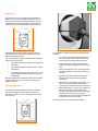
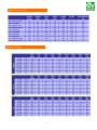
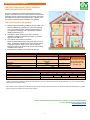
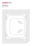
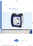
APPENDIX Q ELIGIBLE
HRU ECO 3 RF – Heat Recovery Unit
Technical Brochure
Application
The Combiflow ventilation system with heat recovery unit
HRU ECO 3 RF fan can be applied in different types of
newly built houses.
Description
The heat recovery unit HRU ECO 3 RF is a high efficiency
heat recovery unit. It is provided with a sophisticated
counter-flow heat exchanger by which the unit uses
approximately 95% of the heat of the air that is blown out,
to heat up the fresh air from outside. Each unit, as
standard, has a bypass valve and a unique mechanism to
prevent the unit from freezing. Both mechanisms are fully
integrated in the unit. In addition to this, all units are
delivered with energy saving DC motors.
Characteristics
Weight
As a result of the unique clamping construction in
combination with the plastic/synthetic elements, the weight
of the heat recovery unit HRU ECO 3 RF fan is only 25 kg.
Programme
In table 1 you will find an overview of the heat recovery
unit HRU ECO 3 RF.
Exhaust and Suction Joints
All exhaust and supply air connections have an internal
diameter of 150 mm and external 180 mm. The
connections can be used to attach Vortice modular ducting
and insulated flexible aluminium ducts and accessories.
Each connection is provided with an illustration that shows
the direction and source of the air.
Housing
The connections for the ducts routed into the house are
situated at the lower part of the unit. The motor module
seals the opposite connection. The connections on the
upper part of the unit are used for air extract. As standard,
two connections are sealed with a cap.
Counter Flow Heat Exchanger
Due to the unique patented clamp construction of the HRU
ECO 3 RF fan, the sealing of the various components will
be optimised. Therefore, there will be no internal or
external leakage. The unit can easily be turned around in
case of a house that is ‘mirrored’.
The unique heat exchanger is based on the principle of
counter flow. One of the characteristics of this heat
exchanger is that the incoming and outgoing air is moving
via triangle canals. Because of this each canal is
surrounded by canals in which the current is opposite. This
creates an enormous surface to exchange heat. This
special construction is one of the reasons why an average
of 95% temperature efficiency can be reached.
Table 1
Type
HRU ECO 3 RF
Appliance
Connections to
the House
Exhaust
Inlet
Connections to
the Outside
Exhaust
Inlet
I Family House
Lower Side
Upper Side
Lower Side
~ 1 ~
Upper Side
Inlet and Exhaust
Capacity
Standard
Max
Pressure
225m³h
325m³h
150Pa
Bypass Valve
The heat recovery unit, as standard, is provided with a
bypass valve, which is completely integrated in the unit.
The bypass valve ensures that the air supply is diverted
completely around the heat exchanger. This means the
exhaust air from the dwelling does not heat this fresh air.
Especially during summer nights, this bypass valve is
useful because the temperature outdoors is often lower
than the temperature indoors.
The next steps are taken when the frost protection device
is started:
•
The valve is opened (modulating) and intakes
some air from the area in which the product is
mounted. The air is mixed with the fresh air.
•
At the same time the supply fan will increase
speed to keep the fresh air volume at the same
level.
The fully automatic temperature controller ensures that the
bypass valve is open when:
•
The inside temperature is higher than needed (not
adjustable).
•
The inside temperature is higher than the outside
temperature.
•
The outside temperature is at or above 19° C for a
long period of time (period depends on the exact
temperature).
When the temperature drops, the supply fan will
decrease fan speed, varying until a minimum is
reached.
•
While the temperature is still decreasing, the
exhaust fan will speed up as the supply fan
slows down.
•
With extreme low temperatures the supply fan is
turned off, the frost protection valve will be
closed, but the exhaust fan will keep on running.
•
After approximately 11/2 hours, the air supply fan
will start at a minimum speed and the frost
protection valve will be opened to check whether
the danger of freezing is gone. When the
temperature rises, all above mentioned steps will
be carried out in the reverse order.
•
Both the inside and the outside temperature are measured
inside the HRU ECO 3 RF. Therefore, two sensors are
integral to the unit.
Frost Protection Valve
To prevent the heat exchanger from freezing, a unique
mechanism is standard in the HRU ECO 3 RF. This
mechanism consists of a valve, integrated into the upper
part of the unit.
The above procedure is carried out automatically.
~ 2 ~
Motors
The HRU ECO 3 RF is provided with two energy efficient DC
motors. The fans have backward curved fan blades. The
most important advantage is that the fan will not get very
dirty. This guarantees the capacity of the supply and exhaust
fans.
•
Capacity Setting
•
In the connection unit of the HRU ECO 3 RF are two
trimmers for low speed and high speed adjustment. The mid
speed position is a calculated value between low and high
speeds. The factory setting for high position is 225 m³/h.
Only if the required volumes can not be reached when the
grilles are set in their fully opened position, should the speed
of the unit be increased by this trimmer. This ensures the
lowest energy consumption.
•
The connections to the dwelling can thereafter be
split into two insulated ducts of 150mm diameter
with a Y – piece.
A condensate drain with water seal is required to
provide a water block between where the unit is
mounted and the sewer pipe.
Mains supply must be 220-240 V a.c.
Access to the Unit
The unit should be situated in a position where it can be
accessed for maintenance/servicing. To service the filters
and heat exchanger there must be a space of no less than
500 mm in front of the unit.
Filters
The HRU ECO 3 RF as standard has two G3 grade filters.
One of the filters is placed between the exhaust duct from
the house and the heat exchanger. This filter ensures that
dust and grease are absorbed and therefore the heat
exchanger will become less dirty. The other filter is situated
between the fresh air inlet and the heat exchanger. This filter
is positioned so that fresh air is filtered before it is supplied
into the dwelling. It also prevents the heat exchanger from
becoming dirty.
Important
Ensure that no
foreign objects are
placed on top of the
frost protection
valve, as if the
valves were to open
a foreign object
could fall into the unit
and this would
prevent the
mechanism from
functioning.
Both filters can easily be removed, cleaned and replaced by
the resident.
Installing
The heat recovery unit HRU ECO 3 RF is designed to be
fitted in newly built houses. It is suggested that the unit be
positioned in the loft space.
Installation and User Manual
The installation and user manual are included within the
unit packaging. Before installing the product, it is important
that these instructions be read carefully. Vortice can not
assume any property damage or personal harm resulting in
failure to abide by the instructions. Following the
instructions will assure long service life and overall
mechanical reliability. Therefore, keep the instruction
manuals in a safe place.
The unit can be re-configured so that the duct connections
are opposed to their factory supplied positions. This allows
the unit to be located in different kinds of orientation
dwellings.
Mounting
The unit must be fixed with the mounting bracket, to a wall
with a mass of no less than 200kg/m².
Important Notes
Maintenance
To install the unit correctly, the following points must be
noted:
The maintenance of the unit involves only the following:
•
The exhaust duct to the outside must be minimum
150mm internal diameter, damp proofed and
thermally insulated.
•
The filters should be cleaned when the
construction of the dwelling is completed. The
filters may be dirty with building materials/debris.
•
The inlet duct from the outside must be minimum
150mm internal diameter, damp proofed and
thermally insulated.
•
The filters should be cleaned between 4 and 6
times a year.
•
The air supply duct into the dwelling should include
the supplied sound insulating flexible duct (180mm
diameter) which should be connected to the fan at
the dwelling supply connection.
•
The filters should be replaced at least once a
year. Use only genuine filters available from
Vortice Ltd. New filters are available in pairs.
•
The heat exchanger should be cleaned every 6
years.
•
Depending on the level of dust build up, the motor
and fan blades should be cleaned periodically.
•
The 180mm diameter sound insulating flexible duct
should then be connected to a 180-150mm
reducer.
~ 3 ~
Spare parts can easily be exchanged, preferably without
tools:
•
Filters can be accessed by removing the front
cover.
•
The heat exchanger can also be accessed when
the front cover has been removed.
•
Motors, fans, power supply and controls can be
removed or replaced without disconnecting the
ducts.
•
Data can be extracted from the unit by connecting
a laptop with service software.
Installing RF Control Unit
To Install the RF control switch unit in the kitchen, just
adhere the control unit onto a tile with the supplied
double sided adhesive tape. Alternatively of course, the
control unit can also be fixed with a screw. Each unit is
supplied with an installation and user manual. Do not
place the RF control switch on a metal surface.
Warranty
The unit has a warranty period of 2 years for defective
parts (except for the battery of the RF control switch unit).
Accessories
A heat recovery system consists of different components.
The heart is the HRU ECO 3 RF. More information about
the other components is available from Vortice Ltd.
Electrical Connection
The HRU ECO 3 RF can be connected to a 230V 50Hz
supply. A flying lead is attached to the unit as standard.
When installing the unit, a double pole isolation switch must
be fitted with a minimum contact gap of 3mm. Since the
unit is double insulated it does not need to be earthed. As
standard, the electrical connection on the unit is positioned
on the left hand side. When the unit is reconfigured for
opposite installation the electrical connection will be
positioned on the right hand side.
Additional RF Control Switch Information:
•
Transmission range 100m in free air.
•
Transmission indoors is possible through a
maximum of 2 concrete floors.
•
Pointing of transmitter towards the fan is not
necessary.
•
No external antenna.
Frequency 868 MHz, no licence required.
Control
The heat recovery unit HRU ECO 3 RF can be controlled
by a wireless (RF) 3 speed control unit with timer. Two of
these switch units are included within the fan packaging
and additional RF switches are available from Vortice Ltd.
Wireless (RF) 3 Speed Control Unit with Timer.
The heat recovery unit is provided with two wireless (radio
frequency) remote control switches. The receiver for the
control signal is fitted into the fan during factory production.
The switches, which have a self-adhesive backing, should
be located in the wet rooms; most likely the kitchen and
bathroom within the house and can switch the unit between
speed position one, two and three. Additional transmitters
are available to allow the fan to be controlled from more
rooms; the utility room, en-suites etc.
The last used switch is the master.
Advantages of Wireless Control:
•
No drilling, fixings or electrical wiring is necessary.
•
Control from every room is possible.
•
Additional switches can be added at any time.
•
A better indoor climate, by optimal control.
~ 4 ~
Timer Function
A timer function is also included on the RF control switch.
This timer can be used to switch the ventilation to the
highest speed for a period of time, for instance after an
occupant has used the bathroom. The advantage is that
after the run-on period of the timer, the fan will revert
back to its original speed.
Pressing the timer button once will switch the fan to high
speed for 10 minutes. Pressing the timer button a second
time will switch the unit to high speed for 20 minutes and
a third press of the button will switch the unit to high
speed for 30 minutes. The timer function can be overridden at any time by pressing either of the three speed
buttons.
Technical Specifications
Sound Level Lw (A)
~ 5 ~
Capacity
Dimensions
~ 6 ~
Building Regulations
The system provides quiet, uninterrupted extract
ventilation from the dwelling, removing warm stale
air via all of the “wet” rooms, creating a permanent
air path through the property from the “dry” habitable
rooms.
The 2006 Edition of the U.K. Building Regulations
Approved Document F1: Means of Ventilation
(applicable in England and Wales) details 4 clearly defined
systems of ventilation to dwellings. System 4 Continuous mechanical extract with heat recovery
(MVHR) is complied with, by the new HRU ECO 3 RF ultrahigh efficiency whole house heat recovery ventilation
system.
Air, drawn into the property by the fan, is routed
through an integral high-efficiency synthetic heat
exchanger where warmth from the extracted air is
transferred to the incoming fresh air, before it is
supplied to the habitable rooms.
System 4 - Continuous Mechanical Supply & Extract
with Heat Recovery requires a “minimum high rate” in
each wet room to be achieved (Kitchens 13 l/s and both
utilities and bathrooms 8 l/s (sanitary only 6 l/s)).
In employing this type of system, there is no need to install
background ventilators in the dwelling – an ideal solution to
“noisy” sites.
The “minimum low rate” is calculated by taking the number
of bedrooms in the dwelling and applying the l/s value from
Table 1.1b. In addition, the rate should be no less than
0.3 l/s per m² of internal floor area (all storeys) plus, for
each additional occupant over and above the anticipated
two for the first bedroom and one for each of the others, a
further 4 l/s must be added to the extract rate. Also, there
is an addition of an allowance to be calculated for air
infiltration.
~ 7 ~
Building Regulations – System 4
CONTINUOUS MECHANICAL SUPPLY & EXTRACT
VENTILATION WITH HEAT RECOVERY
A continuous balanced mechanical central supply and extract
system to be positioned in loft or cupboard space. An integral heat
exchanger recovers a large percentage of heat energy that would
have otherwise been lost. In employing this type of system, there
is no need to install background ventilators in the dwelling.
CONTINUOUS SUPPLY AND EXTRACT
1.
Determine the whole building ventilation rate from Table 1.1B.
Allow for infiltration by subtracting for multi storey dwellings:
3
0.04 x gross internal volume of dwelling heated space (m )
for single storey dwellings: 0.06 x gross internal volume of
dwelling heated space (m3).
2.
Calculate the whole dwelling extract rate at maximum
operation by adding the individual room rates for ‘minimum
high rate’ from Table 1.1A.
3.
The required air flow rates are as follows:
Maximum Extract Rate (boost) is the greater step of 1 and 2
above. The Minimum individual room extract rates should be
at least those given in Table 1.1A for minimum high rate.
Minimum air supply rate should be at least the whole building
ventilation rate in 1 above.
4.
No Background ventilators are required with System 4.
Table 1.1 A
Room
Kitchen
Utility Room
Bathroom
Sanitary Accommodation
Minimum Intermittent Extract Rate
30 l/s (adjacent to hob); or 60 l/s
elsewhere.
30 l/s
15 l/s
6 l/s
Continuous Rate
Minimum high
Minimum low rate
rate
Total extract rate must
13 l/s
be at least the whole
building ventilation rate
8 l/s
in Table 1.1B.
8 l/s
Table 1.1 B
Whole Building Ventilation Rate (l/s).
Number of Bedrooms in Dwelling
1
2
3
4
5
13
17
21
25
29
2
Minimum value in any dwelling of 0.3 l/s per m floor area.
In addition, the minimum ventilation rate should not be less than 0.3 l/s per m2 internal floor area (this includes each floor, e.g. for a two-storey building,
add the ground and first floor areas).
This is based on two occupants in the main bedroom and a single occupant in all other bedrooms. This should be used as the default value. If a greater
level of occupancy is expected, then add 4 l/s per occupant.
Vortice Limited, Beeches House, Eastern Avenue, Burton on Trent, DE13 0BB, England
Tel (+44) 1283 492949 Fax (+44) 1283 544121
[email protected]
www.vortice.ltd.uk
~ 8 ~