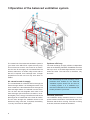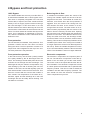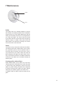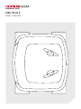
1
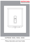
HRU ECO 4
User manual
2
Safety
WARNING
• Do not use this appliance for functions other
than those described in the booklet.
• After removing the appliance from its packaging, ensure that it is complete and undamaged. If in doubt contact Heatrae Sadia. Do
not leave the packaging within reach of children or the infirm.
• Certain fundamental rules must be observed
when using any electrical appliance, including:
a) Never touch appliances with wet or damp
hands
b) Never touch appliances while barefoot.
c) Do not allow children to use the appliance
without supervision.
d) Supervise infirm persons when using the
appliance.
• Store the appliance out of the reach of children
and infirm persons if you decide to disconnect
it from the power supply and no longer use it.
• Do not operate the appliance in the presence
of:
Inflammable substances or vapours (alcohols,
insecticides, petrol, etc).
CAUTION
The following general instructions are important:
• Follow the safety instructions to prevent fan
damage and personal injuries.
• Maintenance instructions must be followed to
prevent damage and/or excessive wear and
tear.
• The specifications in this manual may not be
modified.
• The unit may not be modified.
• The motor module is only suitable for a 230
V 50 Hz a.c system fitted with a 3 amp fuse.
• Do not expose the appliance to the weather
(rain, sun, etc).
• Do not place objects on top of the appliance.
• Regularly inspect the appliance for visible defects. If any faults are found, contact Heatrae
Sadia immediately.
• The appliance must only be installed by a professionally qualified person.
• Ensure that the electrical system to which the
appliance is connected complies with applicable standards.
• Use a multi-polar switch with a minimum
contact gap of 3 mm to install the appliance.
Switch off the appliance at the main switch.
a) If the appliance does not function correctly.
b) Before cleaning the outside of the appliance.
c) If the appliance is not to be used for any
length of time.
• Be careful to avoid damaging the electric circuit.
• Do not use the appliance to control activation
of water heaters, room heaters etc, nor should
it discharge into the flues of any such appliances.
• Ensure that the appliance discharges into a
single duct (dedicated to this product) which
is routed to the outside.
• The air to be extracted from the dwelling must
be clean (i.e. free of grease, soot, chemical
and corrosive agents, explosive or flammable
mixtures).
• Keep the appliance intake and outlet grilles
free to ensure optimum airflow at all times.
3
Safety
Electronic components
The HRU ECO 4 contains parts which may be live.
Consult a professionally qualified installer in the
event of an alleged fault. All repairs and maintenance work should be carried out by a professionally
qualified installer.
Maintenance
The ventilation unit should be inspected regularly for
contamination. Electrically discharge the unit before
carrying out any work on it. First isolate the unit from
the mains supply and make sure that the unit is not
re-connected or the supply plug is not reinserted in
the socket by yourself or anyone else before you
have completed the work.
Rotating parts
The HRU ECO 4 contains rotating mechanical parts.
These parts will keep on turning for a few seconds
after disconnecting the unit from the supply. For this
reason wait at least 10 seconds after isolating the
product before opening the unit. The fan will not be
moving after these 10 seconds have elapsed.
4
Sharp edges of the ducts
The valves and grilles in your home should also be
cleaned regularly. These can be removed from the
wall or ceiling. Beware of protruding duct sections.
These can be very sharp.
Replacing the valves and grilles
The valves should always be placed back in their
original locations. Do not turn the valve during the
cleaning process; or make sure to mark the setting
before cleaning the valve. If the valves are switched
or set differently, the ventilation volumes will no longer be correct and the ventilation system will not work
optimally. The bathroom may then remain humid for
too long, your toilet may be very cool or your kitchen
may smell mouldy.
Maintenance of ducting
It is our recommendation that the ducting connected
to the Extract Terminals (located in kitchens, utilities,
bathrooms and en-suites) needs to be inspected
every 3 years and cleaned every 6 years. Cleaning
of the grille and ducting can be carried out with a
damp cloth.
Table of contents
7. Maintenance 13
8. Warranty conditions 15
9. Manufacturer’s statement 17
8
10. EU Declaration of Conformity 18
9
11. Troubleshooting 19
1. Why use balanced ventilation? 6
2. The correct use of your ventilation
system 7
3. Operation of the balanced ventilation
system 4. Bypass and frost protection 5. Grilles 10
6. System control 11
Subject to changes without notice.
No rights can be derived from this user manual.
5
1 Why use balanced ventilation?
Ventilation is necessary
In the past people built houses which were not airtight, which leaked air, for example, at the connection
point of the wall and the floor or roof. Cracks were
always visible around windows and doors. All these
openings ensured that large volumes of air moved in
and out of the buildings. When the wind was blowing
the complete air content of the home was refreshed
three to four times an hour. This ensured very good
ventilation of the home, but a lot of energy was lost.
Construction methods have changed. Floors, walls
and roofs are, when possible, constructed with a layer of insulation. The insulation ensures that there are
nearly no cracks and the air- tightness is increased.
It is a misconception to think that there is still enough
ventilation in a home without some type of ventilation system. Ventilation is absolutely necessary in an
air-tight home to prevent problems related to humidity, mould and the health of the residents.
6
Moisture content of the home
Incorrect use of the ventilation system by the resident
in combination with today’s well-insulated homes
gives humidity an open field. The moisture content
in the homes increases and can cause health, humidity and mould problems. A family of four persons
produces 14 to 20 litres of moisture per day just by
breathing, sleeping, cooking, washing, dishwashing,
bathing, watering plants, etc. Many products, such
as textile, carpets, parquet, newspapers and cigarettes, contain substances that harm the health of
the residents. All the moisture such as water vapour
and aromatic substances should be removed from
the homes.
2 The correct use of your ventilation system
Ventilation requires energy. The correct use of the
ventilation system can limit energy loss as much as
possible.
Your home has a Heatrae Sadia supplied HRU ECO
4 balanced ventilation system with heat recovery.
This system can contribute extensively to a healthy
interior climate and an optimum comfort level. Another advantage is that the electricity costs are lower
than that of any other ventilation system. The balanced ventilation system can, however, only function
correctly when used and maintained in a responsible
manner.
Some health information:
• 5 to 20% of people have an airway disorder.
The number of house dust mite has increased
a hundredfold in the past 25 years.
• The number of people suffering from Chronic
Non-Specific Lung Disease has doubled in
the last 15 years.
Research has proven that fighting moisture in homes
greatly contributes to the decrease of allergic reactions of people with an airway disorder. The correct
use and maintenance of your balanced ventilation
system makes this possible.
7
3 Operation of the balanced ventilation system
The central unit of the balanced ventilation system in
your home is the HRU ECO 4 (heat recovery unit).
This unit has two motors. One motor for air extraction and one for air supply. Air is extracted from the
kitchen, bathrooms, en-suites, utility rooms and toilets and, if required, from a storage room. In larger
properties more than one unit may have been installed.
Air extraction and air supply
The contaminated air is filtered and fed through the
heat exchanger before it is discharged outside. The
fresh outside air is also filtered and fed through the
heat exchanger before it is allowed into the home.
Two air flows are led alongside each other in the
heat exchanger (the air flows are, therefore, not intermingled). Thus, energy is saved as the heat of the
discharged air is transferred to the fresh air intake.
The air flows through the ventilation ducts to the
bedrooms, living room and, if required, the hallway,
i.e, every room with an intake grille.
8
Optimum efficiency
The heat exchange is highly efficient. Independent
tests at the Building Research Establishment show
that up to 91% of the discharged warmth is reused
within the home. The heat loss is, therefore, only
about 9%.
Not withstanding the heat exchange, which
preheats fresh outside air, the balanced
ventilation system should not be seen as
a heating system. It is a ventilation system that contributes to the comfortable and
healthy climate of your home.
Overflow protection
The installation design assumes there is a 10 mm
space between the bottom of all internal doors, outside door and the floor covering. If the floor covering
is thicker, the doors should be shortened.
4 Bypass and frost protection
100% Bypass
The Heatrae Sadia heat recovery unit HRU ECO 4
is delivered as standard with a 100% bypass valve.
This valve is completely integrated in the unit and
ensures that, if required, the fresh outside air flows
directly to the air supply system instead of through
the heat exchanger. In this case there is no heat
transfer between the warmer discharge air from the
home and the colder intake air that is drawn into the
home. The fresh outside air is blown directly into the
home. This is definitely an advantage in the summer, when the outside air is often cooler than the air
within the home.
Balancing the air flow
The unit includes, as standard, frost protection. This
protection ensures that the unit does not freeze
during the winter. The frost protection consists of a
unique frost valve integrated at the top of the unit.
The frost protection is fully automatic.
In a balanced ventilation system the volume of air
coming from outside equals the amount of air disharged from the home. The outside air suction fan,
therefore, turns faster when the frost protection is
triggered. Thus, the volume of air coming from outside remains the same as the amount of air discharged from the home. The total volume of air intake increases proportionally with the volume of air
taken in from the home by the frost valve. Opening
the frost valve is not sufficient when the outside temperature is even lower. The intake fan will turn more
slowly and, after some time, the discharge ventilator will turn faster. The air, therefore, remains above
freezing. This results in a temporary imbalance of the
ventilation (the volume of air coming from outside is
no longer equal to the amount of air discharged from
the home). When the outside temperature increases, the unit automatically resets the fans to the initial
values. The ventilation is thus once again balanced.
Frost protection operation
Electronic components
Frost protection
In the heat recovery unit the fresh (colder) outside
air is partly heated by the air discharged from the
home. The exchange of heat takes place when both
air flows are led through the heat exchanger. The
discharged air may be cooled to a temperature very
near freezing by the cold air entering the unit from
outside. In this case, the unit will regularly open the
frost valve and take in warm air from the home. This
warm air is mixed with the cold air that is taken in
from outside. The temperature of the intake air is,
therefore, higher and the discharge air in the heat
exchanger will also be safely above freezing. The
unit will thus not freeze.
The electronic components are important parts of
the unit. The electronic components control the operation of the unit when you set the mode switch.
The motor is set to the speed that ensures the desired ventilation. The electronic components consist
of a basic printed circuit board and an optional radio
frequency module. This can be used to extend the
ventilation unit with radio frequency operation. The
user should not touch the electronic components.
These components may be live.
9
5 Grilles
Grilles
The volume of air that has to be extracted is specified in the Building Regulations. The volume of air
flowing into the home has to be in balance with the
extracted volume. The volume of air extracted from
and supplied to the home should, in other words,
be equal. The minimum air volume per room is also
determined by the Building Regulations. The set
volume of air is determined based on achieving an
optimum home climate without wasting energy. The
air intake and discharge per room are not equal. The
extraction and intake grilles all have their own fixed
positions and settings.
Extract Valve
Supply Valve
The setting of the grilles should not be
changed. Changing the settings may disrupt the operation of the complete ventilation system. Grilles and valves should
not be switched with each other.
10
6 System control
The HRU ECO 4 ‘Combiflow’ system has been designed to recover as much heat as possible and to
function well using as little energy as possible. The
Heatrae Sadia HRU ECO 4 can be operated using a
radio frequency operation switch.
Hard wired 3 position switch
Radio frequency (RFT) operation switch
The RFT (radio frequency) operation switch (transmitter) can be used as a 3-position mode switch with
timer feature for the HRU ECO 4 ventilation unit. This
operation switch can be used to set the ventilation
unit to one of the three ventilation modes (capacities): The modes are:
Mode 1 - Low mode.
Mode 2 - Medium mode.
Mode 3 - High mode.
The HRU ECO 4 can be operated using the 3 position switch.
The low mode is a continuous background setting,
the medium mode can be used for improved comfort
and the high mode when cooking, showering or bathing. The switch also has a timer. The ventilation unit
can be switched to high mode for a predetermined
time by pressing the timer button. The timer automatically switches the ventilation unit to low mode after
the time has elapsed.
HRS-3. Step one is used at night, step two during
the day when there are people at home and step
three when cooking, showering or bathing.
RFT operation switch.
The length of time set for the timer is determined by
the user.
Press the timer button once to set the ventilation unit
to high mode for 10 minutes.
Press the timer button twice to set the ventilation unit
to high mode for 20 minutes.
Press the timer button three times to set the ventilation unit to high mode for 30 minutes.
If the operation switch is used by choosing mode or while the timer is in operation, the timer
is switched off and the ventilation unit operates in
the chosen mode.
11
Recommended hours of operation
A new home contains approximately 2000 litres of
moisture in its floors and walls. This moisture has to
be removed from the home. It is recommend that a
new home be ventilated more intensively during the
first few months. For example, by setting the ventilation system to medium mode instead of low mode
during the day time. The recommended hours of operation are provided in the list below.
To guarantee a healthy environment in your home
we recommend the following daily hours of operation for the ventilation system:
At most 14 hours in low mode.
At least 8 hours in medium mode.
At least 2 hours in high mode.
12
7 Maintenance
Airflow
Valve
Grilles
The grilles have to be cleaned regularly to ensure
the constant and reliable operation of the ventilation
system and for your own health. Make sure that the
setting of the system (air flow) is not changed when
you clean the grilles. The valve could be turned
by accident and this would mean that the opening
becomes larger or smaller. Each grille should be
placed back in the same duct opening in the same
room from which it was removed.
Filters
The heat recovery unit and the extractor have filters.
The filters prevent the contamination of the ventilation, guarantee years of correct operation and ensure that clean air is blown into your home. This is
very important for your health. Check and clean the
filters regularly and replace the filters when necessary. This ensures the home is ventilated sufficiently
at all times. The filters can be cleaned manually by
washing them.
Cleaning grilles without filters
Grilles without filters can be taken out of the duct
opening (twist to the left). Before you clean the grille
in warm water (with detergent), remove the foam
plastic ring. After cleaning, the grille can be replaced
in the duct opening with a twist to the right. Always
make sure you replace a grille in the same room.
In addition make sure NOT to alter the setting of the
grille.
13
An air trap with a minimum level difference of 250
mm is added in this connection. Above the air trap,
a branch pipe is mounted at a 45-degree angle. This
branch pipe has a cover with a rubber ring. This can
be opened to easily top up the water trap. This is
required to maintain or restore the water trap.
Fixed coupling with fill opening
If the air trap runs dry, the air from the house sewerage will be able to enter through the unit and be
discharged outside by the discharge ventilator. No
smell will be caused but the discharge capacity will
decrease. We recommend refilling the air trap quarterly. The water will evaporate more quickly in summer.
Removing the front of the unit.
Smells near the coupling with the condensation discharge hose
Condensate discharge
The warm contaminated air passes along the colder
fresh outside air in the heat exchanger of the heat
recovery unit. This can often result in condensate
being formed, therefore the HRU ECO 4 has an integral condensate discharge drain. This drain has a
PVC coupling with a 40 mm external diameter. The
installer connects this coupling of the heat recovery
unit to the house sewerage grey water system or
surface water drain pipe using a separate removable
rubber coupling.
siphon
14
When the air trap runs dry, a direct connection with
the house sewerage is created. This creates smells.
Refill the air trap using the fill opening to solve the
problem. Effective discharge of cooking and baking
vapours in the kitchen is guaranteed by the extractor. The extractor is connected to the balanced ventilation system.
It is preferable to have a registered installer
carry out the cleaning.
siphon
8 Warranty conditions
The Heatrae Sadia HRU ECO 4 warranty is valid for
2 years after installation date. The installation date is
indicated on the type plate.
The warranty does not apply to:
• Disassembly and assembly costs.
• Faults which are, in our opinion, caused by incorrect treatment, negligence or an accident.
• Faults that have been caused by repairs or
intended repairs by third parties without our
authorisation.
• Faults caused by irregular and / or incompetent maintenance.
• Modification to the appliance.
• Incorrect installation of the appliance.
• Incorrect power supply, please refer to page 3
for correct power supply.
Should the unit become damaged or malfunction,
switch it off, isolating it from the mains supply, and
contact Heatrae Sadia immediately.
The warranty is only valid if the warranty card was
filled in by your supplier on the date of installation
and if it is sent along with any request for repair (a
receipt including the date of installation is also acceptable). This warranty card should be filled in on
the installation date and be kept by the user.
Type House / Apartment (delete as appropriate)
Serial number
Voltage
Installation date
Supplier seal
15
Spares
4
2
1
Item No.
1
2
3
4
16
Heatrae Sadia HRU
Part
Fan (1 only)
PCB Set
Sensors (not shown)
Frost Valve
Part No.
95607722
95615088
95607723
95605905
9 Manufacturer’s statement
EC declaration of conformity
According to Low Voltage Directive 2006/95/EC and the EMC Directive 2004/108/EC.
Declaration of Incorporation
According to Annex IIB of the Machinery Directive 2006/42/EC,
Heatrae Sadia Heating
Hurricane Way Norwich NR6 6EA
hereby declare under our sole responsibility that the following products:
Heat Recovery Ventilation System
Type: HRU ECO 4
is in conformity with the following EC Council Directives:
- Low Voltage Directive 2006/95/EC
- EMC Directive 2004/108/EC
and Applied Harmonised Standards:
- EN60730-1
- EN61000-3-2
- EN61000-6-1
- EN61000-6-3
- RoHs / Weee
and must be regarded as partly completed machinery and is intended to be incorporated in a machine or to be
assembled with other machines into a single machine or system to which the Machinery Directive 2006/42/EC
applies.
We want to alert you that the product is designed to be incorporated in a ventilation system and that the partly
completed machine must not be put into service until the final machinery into which it is to be incorporated is in
conformity with the provisions of Machinery Directive 2006/42/EC for which the most important instructions can
be found in the manual.
We explicitly state that the CE marking on the product only refers to the Low Voltage Directive 2006/95/EC and
the EMC Directive 2004/108/EC.
After the submission of a declaration according to Annex IIA of the Machinery Directive for the entire installation,
the CE marking on the device also refers to the Machinery Directive 2006/42/EC.
17
10 EU Declaration of Conformity
EC declaration of conformity
According to Annex II of the Machinery Directive 2006/42/EC
We:
Name of installer:
Full address and country:
Hereby declare under our own responsibility, to have installed the following product with type designation:
Heat Recovery Ventilation
Type: HRU ECO 4
to which this declaration refers. We declare the entire installation (being a single machine) in conformity with the
Machinery Directive.
Place:
Date:
Name:
Position:
Signature:
Company Stamp:
18
11 Troubleshooting
Problem
Troubleshooting
Fans do not turn.
No power supply.
Mains voltage failure.
Wall socket power supply failure.
Check the distribution board in the fuse
cabinet/meter cupboard.
Check whether the 230 Volt plug is
placed correctly in the unit.
Intake fan does not turn.
Little or no air is coming through
the intake grilles.
Frost protection is activated.
Clean the filters.
Discharge fan does not turn.
No suction through the discharge
grilles.
Clean the filters.
Low volume of intake air.
Low volume of air through intake
grilles.
Clean the filters.
Exchanger is partially frozen shut
(frost protection failure).
Low volume of discharge air.
Low volume of air to discharge
grilles.
Clean the filters.
Exchanger is partially frozen shut
(frost protection failure).
Condensation leakage.
Drops of water on bottom of the
unit.
Condensation discharge is clogged.
Leaking condensation discharge.
Unpleasant smell.
Near the unit.
Near intake grilles.
Air trap under the unit is dry.
Distance between outside air suction
and ventilation outlet is too small.
Noise.
Swishing sound from the air flow.
The duct system is creating too much
resistance.
Valves are not opened sufficiently.
Valves do not fit the duct properly.
Too much resistance due to contamination of filters or exchanger frozen).
Rattling noise.
Fan does not run true or is faulty.
Gurgling noise.
The air trap is dry.
Condensation discharge is not sufficiently deep in the air trap.
If the problem persists, report the details to the installer.
Climate for life
Heatrae Sadia at all times strive to offer people an enjoyable living and working environment with its innovative
solutions in climate systems. These are solutions for temperature, clean air and hot water in the domestic environment in which people and environment go harmoniously together. We want a more comfortable and healthier
living environment but at the same time, we aim for lower energy consumption. With sustainable technologies
and innovations, Heatrae Sadia proves that seemingly opposite objectives can be combined with very little effort. Our aim is to develop climate systems that respect the world around us. Your wishes become our inspiration and Heatrae Sadia works constantly to achieve this: Climate for life.
19
HEATRAE SADIA HEATING
Hurricane Way, Norwich NR6 6EA
www.heatraesadia.com
SERVICE
0844 8711535
SERVICE FAX
0844 8711528
EMAIL
[email protected]
20
36006179_issue_01