1
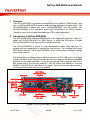
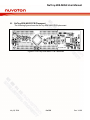
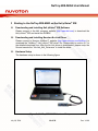
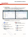
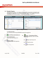
NuTiny-SDK-M453 User Manual ARM Cortex®-M4 32-BIT MICROCONTROLLER NuTiny-SDK-M453 User Manual for NuMicro™ M453 Series The information described in this document is the exclusive intellectual property of Nuvoton Technology Corporation and shall not be reproduced without permission from Nuvoton. Nuvoton is providing this document only for reference purposes of NuMicro™ microcontroller based system design. Nuvoton assumes no responsibility for errors or omissions. All data and specifications are subject to change without notice. For additional information or questions, please contact: Nuvoton Technology Corporation. July 16, 2014 Rev. V1.00 NuTiny-SDK-M453 User Manual Table of Contents 1 Overview ........................................................................................... 3 2 Introduction to NuTiny-SDK-M453 ........................................................ 3 2.1 2.2 2.3 Starting to Use NuTiny-SDK-M453 on the Keil μVision® IDE ................... 10 3 3.1 3.2 3.3 3.4 4 Downloading and Installing Keil μVision® IDE Software ................................. 10 Downloading and Installing Nuvoton Nu-Link Driver ..................................... 10 Hardware Setup ....................................................................................... 10 Example Program..................................................................................... 11 Starting to Use NuTiny-SDK-M453 on the IAR Embedded Workbench ...... 12 4.1 4.2 4.3 4.4 5 Downloading and Installing IAR Embedded Workbench Software .................... 12 Downloading and Installing Nuvoton Nu-Link Driver ..................................... 12 Hardware Setup ....................................................................................... 12 Example Program..................................................................................... 13 NuTiny-SDK-M453 Schematics ........................................................... 14 5.1 5.2 6 NuTiny-EVB-M453 Schematic .................................................................... 14 Nu-Link-Me Schematic .............................................................................. 18 Downloading NuMicro™ Related Files from Nuvoton Website .................. 19 6.1 6.2 6.3 7 NuTiny-SDK-M453 System Description .........................................................4 Pin Assignment for Extended Connectors ......................................................6 NuTiny-SDK-M453 PCB Placement ...............................................................9 Downloading NuMicro™ Keil μVision® IDE Driver .......................................... 19 Downloading NuMicro™ IAR EWARM Driver ................................................. 21 Downloading NuMicro™ M453 Series BSP Software Library ............................ 23 Revision History ............................................................................... 24 July 16, 2014 2 of 26 Rev. V1.00 NuTiny-SDK-M453 User Manual 1 Overview The NuTiny-SDK-M453 is a specific development tool for NuMicro™ M453 Series. User can use NuTiny-SDK-M453 to develop and verify the application program easily. The NuTiny-SDK-M453 includes two parts: NuTiny-EVB-M453 and Nu-Link-Me. The NuTiny-EVB-M453 is the evaluation board and Nu-Link-Me is its Debug Adaptor. Therefore, user does not need other additional ICE or debug equipment. 2 Introduction to NuTiny-SDK-M453 The NuTiny-SDK-M453 uses the M453VG6AE as the target microcontroller. Figure 2-1 shows the NuTiny-SDK-M453 for M453 Series, in which the left portion is called NuTiny-EVB-M453 and the right portion is called Nu-Link-Me. The NuTiny-EVB-M453 is similar to other development boards. User can use it to develop and verify applications to emulate the real behavior. The on-board chip covers M453 Series features. The NuTiny-EVB-M453 can be a real system controller to design users’ target systems. The Nu-Link-Me is a Debug Adaptor, which connects your PC's USB port to your target system (via Serial Wired Debug port) and allows you to program and debug embedded programs on the target hardware. To use the Nu-Link-Me Debug Adaptor with IAR or Keil, please refer to the “Nuvoton NuMicro™ IAR ICE Driver User Manual“ or “Nuvoton NuMicro™ Keil ICE Driver User Manual” for details. The two documents will be stored in the local hard disk when each driver is installed. Power LED LQFP-100 pin Extended Connector (JP6, JP8) VCC5 (JP1) Reset Key (SW1) USB OTG Connector (CON1/J3) ICE Controller USB Connector (J2) Target Chip GND (JP4) LQFP-100 pin Extended Connector (JP5, JP7) IO LED (PC.9) ICE Controller VCC:3.3V or 5V (JPR1) Figure 2-1 NuTiny-SDK-M453 (Blue PCB Board) July 16, 2014 3 of 26 Rev. V1.00 NuTiny-SDK-M453 User Manual 2.1 NuTiny-SDK-M453 System Description 2.1.1 Power Settings J2: USB port in Nu-Link-Me CON1/J3: Micro USB port in NuTiny-EVB-M453 JP1: VCC5V voltage connector in NuTiny-EVB-M453 POWER Mode J2 USB Port (Mini) CON1/J3 USB Port (Mini/Micro) JP1 VCC5V MCU Voltage Mode 1 Connected to PC X DC 3.3V or 5V Output DC 3.3V or 5V Mode 2 X Connect to PC (USB port is device) DC 3.3V or 5V Output DC 3.3 V or 5V Mode 3 X Connect to USB device (USB port is host) DC 5V Input DC 5V Comment J2 (from PC) supplies the power. MCU voltage can be selected to 3.3V or 5V through JPR1. CON1/J3 (from PC) supplies the power when pins of JP14 are shorted together. JP1 supplies the power when JP1 is wired to pin1 of JP14 . X: Unused. 2.1.2 Debug Connectors JP2: The connector in the target board (NuTiny-EVB-M453) for connecting with Nuvoton ICE adaptor (Nu-Link, Nu-Link-Pro or Nu-Link-Me) JP11: The connector in the ICE adaptor (Nu-Link-Me) for connecting with a target board (e.g. NuTiny-EVB-M453) 2.1.3 USB Connector J2: Mini USB connector in Nu-Link-Me connected to a PC USB port 2.1.4 USB OTG Host/Device Connector CON1/J3: Mini/Micro USB connector in NuTiny-EVB-M453 for application use 2.1.5 Extended Connectors JP5, JP6, JP7 and JP8: Show all chip pins in NuTiny-EVB-M453 2.1.6 Reset Buttons SW1: Reset button in NuTiny-EVB-M453. Press this key to reset the target chip M453VG6AE. July 16, 2014 4 of 26 Rev. V1.00 NuTiny-SDK-M453 User Manual 2.1.7 Power Connectors JPR1: An option to select whether the 3.3V voltage input supplied by the ICE bridge (default) VBAT: The VBAT connector in NuTiny-EVB-M453 to supply an extra battery power for RTC application. The default is shorted with VCC33. VREF: The VREF connector in NuTiny-EVB-M453 to supply an external reference voltage for analog peripherals. The default is shorted with VCC33. VDDIO: The VDDIO connector in NuTiny-EVB-M453 to supply a special voltage for some GPIOs. The default is shorted with VCC33. JP1: VCC5V connector in NuTiny-EVB-M453 to supply target chip voltage from an extra power supplier. JP4: GND connector in NuTiny-EVB-M453 July 16, 2014 5 of 26 Rev. V1.00 NuTiny-SDK-M453 User Manual 2.2 Pin Assignment for Extended Connectors The NuTiny-EVB-M453 provides the M453VG6AE target chip on board and the extended connectors (JP5, JP6, JP7 and JP8) for LQFP 100-pin. No Pin Name No Pin Name 1 PB.13/EADC_CH10 24 PF.1/X32_IN 2 PB.14/EADC_CH11 25 PF.2/TAMPER 3 PB.15/EADC_CH12/TK2/ACMP0_P3/EBI_nCS1 26 PD.10/T2 27 PD.11/T3 4 5 6 PB.5/EADC_CH13/SPI0_MOSI0/SPI1_MOSI/TK3/ ACMP0_P2/EBI_AD6 PB.6/EADC_CH14/SPI0_MISO0/SPI1_MISO/TK4/ ACMP0_P1/EBI_AD5 PB.7/EADC_CH15/SPI0_CLK/SPI1_CLK/TK5 ACMP0_P0/EBI_AD4 28 29 PD.12/SPI2_SS/UART3_TXD/PWM1_CH0/ EBI_ADR16 PD.13/SPI2_MOSI/UART3_RXD/PWM1_CH1/ EBI_ADR17 PD.14/SPI2_MISO/UART3_nCTS/PWM1_CH2 EBI_ADR18 PD.15/SPI2_CLK/UART3_nRTS/PWM1_CH3/ EBI_ADR19 PD.7/PWM0_SYNC_IN/T1/ACMP0_O/PWM0_CH5/ EBI_nRD 7 nRESET 30 8 PD.0/SPI1_I2SMCLK/UART0_RXD/TK6 ACMP1_N/INT3 31 9 AVSS 32 10 VDD 33 PF.3/XT1_OUT/I2C1_SCL 11 VSS 34 PF.4/XT1_IN/I2C1_SDA 12 PC.8/TK7 35 VSS 13 PD.8/TK8/EBI_nCS0 36 VDD 14 PD.9/TK9/ACMP1_P3/EBI_ALE 37 LDO_CAP 38 PC.9/SPI2_I2SMCLK/PWM1_CH0 39 PC.10/SPI2_MOSI/PWM1_CH1 40 PC.11/SPI2_MISO/PWM1_CH2 41 PC.12/SPI2_CLK/PWM1_CH3 42 PC.13/SPI2_SS/PWM1_CH4 PC.14/PWM1_CH5 15 16 17 18 19 PD.1/PWM0_SYNC_IN/UART0_TXD/TK10/ ACMP1_P2/T0/EBI_nRD PD.2/STADC/T0_EXT/TK11/ACMP1_P1 PWM0_BRAKE0/EBI_nWR/INT0 PD.3/T2/T1_EXT/TK12/ACMP1_P0/ PWM0_BRAKE1/EBI_MCLK/INT1 PD.4/SPI1_CLK/I2C0_SDA/TK13/ PWM0_BRAKE0/T0 PD.5/CLKO/SPI1_MISO/I2C0_SCL/TK14/ PWM0_BRAKE1/T1 20 PE.3/SPI1_MOSI/TK15/PWM0_CH3 43 21 PD.6/CLKO/SPI1_SS/UART0_RXD/TK16 ACMP0_O/PWM0_CH5/EBI_nWR/ 44 22 VBAT 45 23 PF.0/X32_OUT/INT5 46 July 16, 2014 6 of 26 PC.0/SPI2_CLK/UART2_nCTS/CAN0_TXD/ PWM0_CH0/EBI_AD8/INT2 PC.1/CLKO/STDAC/UART2_nRTS/CAN0_RXD/ PWM0_CH1/EBI_AD9 PC.2/SPI2_SS/UART2_TXD/ACMP1_O/ Rev. V1.00 NuTiny-SDK-M453 User Manual PWM0_CH2/EBI_AD10 47 48 49 PC.3/SPI2_MOSI/UART2_RXD/USB_VBUS_ST/ PWM0_CH3/EBI_AD11 PC.4/SPI2_MISO/I2C1_SCL/USB_VBUS_EN/ PWM0_CH4/EBI_AD12 PE.0/SPI2_CLK/I2C1_SDA/T2_EXT/SC0_CD/ PWM0_CH0/EBI_nCS1/INT4 73 USB_VBUS 74 USB_D- 75 USB_D+ 50 PC.5/SPI2_I2SMCLK/PWM0_CH5/EBI_AD13 76 USB_ID 51 PC.6/I2C1_SMBAL/ACMP1_O/PWM1_CH0/ EBI_AD14 77 USB_VDD33_CAP 52 PC.7/I2C1_SMBSUS/PWM1_CH1/EBI_AD15 78 PE.2/PWM1_CH1 53 54 PE.4/I2C1_SCL/SC0_PWR/PWM1_BRAKE0/ EBI_nCS0/INT0 PE.5/I2C1_SDA/SC0_RST/PWM1_BRAKE1/ EBI_ALE/INT1 79 80 PA.3/USB_VBUS_ST/UART0_RXD/UART0_nRTS/ I2C0_SCL/SC0_PWR/PWM1_CH2/EBI_AD3 PA.2/USB_VBUS_EN/UART0_TXD/UART0_nCTS/ I2C0_SDA/SC0_RST/PWM1_CH3/EBI_AD2 PA.1/UART1_nRTS/UART1_RXD/CAN0_TXD/ SC0_DAT/PWM1_CH4/EBI_AD1 PA.0/UART1_nCTS/UART1_TXD/CAN0_RXD/ SC0_CLK/PWM1_CH5/EBI_AD0/INT0 55 PF.5/ICE_CLK 81 56 PF.6/ICE_DAT 82 57 PA.8/UART3_TXD 83 PA.12/SPI1_I2SMCLK/CAN0_TXD 58 PA.9/UART3_RXD 84 PA.13/CAN0_RXD 59 PA.7/SPI1_CLK/T0_EXT/EBI_AD7 85 PA.14/UART2_nCTS/I2C0_SMBAL 60 PA.6/SPI1_MISO/T1_EXT/EBI_AD6 86 PA.15/UART2_nRTS/I2C0_SMBSUS 61 PA.5/SPI1_MOSI/T2_EXT/EBI_AD5 87 VSS 62 PA.4/SPI1_SS/EBI_AD4 88 VDD 63 VSS 89 AVDD 64 VDD 90 VREF 65 PE.1/T3_EXT/SC0_CD/PWM0_CH1 91 66 67 68 69 70 71 72 PE.8/UART1_TXD/SPI0_MISO1/I2C1_SCL/ SC0_PWR PE.9/UART1_RXD/SPI0_MOSI1/I2C1_SDA/ SC0_RST PE.10/SPI1_MISO/SPI0_MISO0/UART1_nCTS/ I2C0_SMBAL/SC0_DAT PE.11/SPI1_MOSI/SPI0_MOSI0/UART1_nRTS/ I2C0_SMBSUS/SC0_CLK PE.12/SPI1_SS/SPI0_SS/UART1_TXD/ I2C0_SCL PE.13/SPI1_CLK/SPI0_CLK/UART1_RXD/ I2C0_SDA VDDIO July 16, 2014 92 93 94 95 PB.0/EADC_CH0/SPI0_MOSI1/UART2_RXD/ T2/DAC/EBI_nWRL/INT1 PB.1/EADC_CH1/SPI0_MISO1/UART2_TXD/T3/ SC0_RST/PWM0_SYNC_OUT/EBI_nWRH PB.2/EADC_CH2/SPI0_CLK/SPI1_CLK/ UART1_RXD/SC0_CD PB.3/EADC_CH3/SPI0_MISO0/SPI1_MISO/ UART1_TXD PB.4/EADC_CH4/SPI0_SS/SPI1_SS/ UART1_nCTS/ACMP0_N/EBI_AD7 96 PB.8/EADC_CH5/UART1_nRTS/PWM0_CH2 97 PB.9/EADC_CH6 98 PB.10/EADC_CH7 7 of 26 Rev. V1.00 NuTiny-SDK-M453 User Manual 99 PB.11/EADC_CH8/TK0 100 PB.12/EADC_CH9/TK1 Table 2-1 M453VG6AE LQFP 100-pin Assignment for Extended Connectors July 16, 2014 8 of 26 Rev. V1.00 NuTiny-SDK-M453 User Manual 2.3 NuTiny-SDK-M453 PCB Placement The following figure shows the NuTiny-SDK-M453 PCB placement. Figure 2-2 NuTiny-SDK-M453 PCB Placement July 16, 2014 9 of 26 Rev. V1.00 NuTiny-SDK-M453 User Manual 3 Starting to Use NuTiny-SDK-M453 on the Keil μVision® IDE 3.1 Downloading and Installing Keil μVision® IDE Software Please connect to the Keil company website (http://www.keil.com) to download the Keil μVision® IDE and install the RVMDK. 3.2 Downloading and Installing Nuvoton Nu-Link Driver Please connect to Nuvoton NuMicro™ website (http://www.nuvoton.com/NuMicro) to download the “NuMicro™ Keil μVision® IDE driver” file. Please refer to section 6.1 for the detailed download flow. After the Nu-Link driver is downloaded, please unzip the file and execute the “Nu-Link_Keil_Driver.exe” to install the driver. 3.3 Hardware Setup The hardware setup is shown in the following figure. Figure 3-1 NuTiny-SDK-M453 Hardware Setup July 16, 2014 10 of 26 Rev. V1.00 NuTiny-SDK-M453 User Manual 3.4 Example Program This example, as shown in the directory in Figure 3 2, demonstrates downloading and debugging an application on a NuTiny-SDK-M453 board. The example file can be downloaded from Nuvoton NuMicro™ website as described in section 6.3. Directory Project File Figure 3-2 Example Directory To use the example: The I/O LED on the NuTiny-EVB-M453 board will be toggled on. Start μVision® Project – Open Open the led.uvproj project file Start Debug mode When using the debugger commands, you may: Review variables in the watch window Single step through code Reset the device Run the application Project – Build Compile and link the LED application Flash – Download Program the application code into on-chip Flash ROM July 16, 2014 11 of 26 Rev. V1.00 NuTiny-SDK-M453 User Manual 4 Starting to Use NuTiny-SDK-M453 on the IAR Embedded Workbench 4.1 Downloading and Installing IAR Embedded Workbench Software Please connect to IAR company website (http://www.iar.com) to download the IAR Embedded Workbench and install the EWARM. 4.2 Downloading and Installing Nuvoton Nu-Link Driver Please connect to Nuvoton Company NuMicro™ website (http://www.nuvoton.com/NuMicro) to download “NuMicro™ IAR EWARM Driver” file. Please refer to section 6.2 for the detail download flow. After the Nu-Link driver is downloaded, please unzip the file and execute the “Nu-Link_IAR_Driver.exe” to install the driver. 4.3 Hardware Setup The hardware setup is shown in the following figure. Figure 4-1 NuTiny- SDK-M453 Hardware Setup July 16, 2014 12 of 26 Rev. V1.00 NuTiny-SDK-M453 User Manual 4.4 Example Program This example, as shown in the directory in Figure 4-2, demonstrates downloading and debugging an application on a NuTiny-SDK-M453 board. The example file can be downloaded from Nuvoton NuMicro™ website as described in section 6.3. Directory Project File Figure 4-2 Example Directory To use the example: The I/O LED on the NuTiny-EVB-M453 board will be toggled on. Start IAR Embedded Workbench File-Open-Workspace Open the led.eww workspace file Project - Make Compile and link the LED application July 16, 2014 Project – Download and Debug Program the application code into on-chip Flash ROM Single step through code Reset the device Run the application 13 of 26 Rev. V1.00 NuTiny-SDK-M453 User Manual 5 NuTiny-SDK-M453 Schematics 5.1 NuTiny-EVB-M453 Schematic VDDIO VDD 0ohm U1 M453VG6AE LQFP-100 USB_ID C11 1u C0603 USB_OC# USB_PWR_EN 76 77 78 79 80 81 82 83 84 85 86 87 88 89 90 91 92 93 94 95 96 97 98 99 100 USB_ID USB_LDO_CAP PE.2 PA.3_SC_PWR/USB_ST PA.2/SC_RST/USB_EN PA.1/CAN_TX/SC_DAT PA.0/CAN_RX/SC_CLK PA.12/CAN_TX PA.13/CAN_RX PA.14 PA.15 VSS VDD AVDD VREF PB.0/AIN0/DAC PB.1/AIN1 PB.2/AIN2 PB.3/AIN3 PB.4/AIN4 PB.8/AIN5 PB.9/AIN6 PB.10/AIN7 PB.11/AIN8 PB.12/AIN9 PC.5 PE.0/SPI2_CLK/SC_CD/I2C1_SDA PC.4/SPI2_MISO/I2C1_SCL/USB_EN PC.3/SPI2_MOSI/USB_ST PC.2/CMP1_O/SPI2_CS# PC.1/CAN_RX/CKO PC.0/CAN_TX/SPI2_CLK PC.14 PC.13/SPI2_CS# PC.12/SPI2_CLK PC.11/SPI2_MISO PC.10/SPI2_MOSI PC.9 LDO_CAP VDD VSS PF.4/I2C1_SDA/XT1_I PF.3/I2C1_SCL/XT1_O PD.7/CMP0_O/TM1 PD.15/SPI2_CLK PD.14/SPI2_MISO PD.13/SPI2_MOSI PD.12/SPI2_CS# PD.11/TM3 PD.10/TM2 50 49 48 47 46 45 44 43 42 41 40 39 38 37 36 35 34 33 32 31 30 29 28 27 26 P50 P49 P48 P47 P46 P45 P44 P43 P42 P41 P40 P39 P38 P37 P36 P35 P34 P33 P32 P31 P30 P29 P28 P27 P26 PC9 VDD C12 D12MI D12MO 1u C0603 P1 P2 P3 P4 P5 P6 P7 P8 P9 P10 P11 P12 P13 P14 P15 P16 P17 P18 P19 P20 P21 P22 P23 P24 P25 1 2 3 4 5 6 7 8 9 10 11 12 13 14 15 16 17 18 19 20 21 22 23 24 25 VDD AVDD VREF P76 P77 P78 P79 P80 P81 P82 P83 P84 P85 P86 P87 P88 P89 P90 P91 P92 P93 P94 P95 P96 P97 P98 P99 P100 PB.13/AIN10 PB.14/AIN11 PB.15/TK2/AIN12/CMP0_P3 PB.5/AIN13/CMP0_P2/SPI0_MOSI0/SPI1_MOSI PB.6/AIN14/CMP0_P1/SPI0_MISO0/SPI1_MISO PB.7/AIN15/CMP0_P0/SPI0_CLK/SPI1_CLK RESET# PD.0/CMP1_N/UART0_RXD AVSS VDD VSS PC.8 PD.8 PD.9/CMP1_P3 PD.1/CMP1_P2/UART0_TXD/TM0 PD.2/CMP1_P1/TM0_EXT PD.3/CMP1_P0/TM1_EXT/TM2 PD.4/SPI1_CLK/I2C0_SDA PD.5/SPI1_MISO/I2C0_SCL/CLKO PE.3/SPI1_MOSI PD.6/CMP0_O/SPI1_CS#/UART0_RXD VBAT PF.0/X32_O PF.1/X32_I PF.2/TAMPER USB OTG LDO Multi-function Pins USB_D+ USB_DVBUS VDDIO PE.13/SPI0_CLK PE.12/SPI0_CS# PE.11/SPI0_MOSI PE.10/SPI0_MISO PE.9/SPI0_MOSI1 PE.8/SPI0_MISO1 PE.1/SC_CD/TM3_EXT VDD VSS PA.4/SPI1_CS# PA.5/SPI1_MOSI/TM2_EXT PA.6/SPI1_MISO/TM1_EXT PA.7/SPI1_CLK PA.9/UART3_RX PA.8/UART3_TX PF.6/ICE_DAT PF.5/ICE_CLK PE.5/I2C1_SDA PE.4/I2C1_SCL PC.7 PC.6/CMP1_O 75 74 73 72 71 70 69 68 67 66 65 64 63 62 61 60 59 58 57 56 55 54 53 52 51 P75 P74 P73 P72 P71 P70 P69 P68 P67 P66 P65 P64 P63 P62 P61 P60 P59 P58 P57 P56 P55 P54 P53 P52 P51 VDD ICEDAT ICECLK 0.1u C0603 USB_D+ USB_DUSB_VBUS C21 1 2 DX32O DX32I ICERST VDD VDD C0603 0.1u C13 0ohm 2 1 VBAT ADAVSS July 16, 2014 14 of 26 Rev. V1.00 NuTiny-SDK-M453 User Manual Crystal C1 20p C2 20p XTAL-3.4MM-2P C0603 R2 0 R0603 DX32O R6 0 R0603 DX32I C0603 32.768K X1 C9 20p C0603 C10 20p X2 12MHz D12MO R7 0 R0603 D12MI XTAL3-1 C0603 Reset R3 0 R0603 VDD SW1 PUSH BOTTOM SW R1 10K R0603 ICERST C8 10uF/10V TANT-A USB Host/Device USB_VBUS VDD DD+ USB_ID D1 2 2 1 D2 NC RB060L NC 2 1 VCC5 1 SS24A RB060L 2 JP9 0ohm-R8050 1 JP14 0ohm-R8050 J1 1 2 3 4 5 U2 5 USB_PWR_EN 4 R9 NC R0603 J3 OUT IN GND EN/EN# OC# USB_VBUS 1 1 USB_D-R8 2 3 CT1 + 1uF/6.3V USB_OC# TANT-A NCT3520U CB1 0.1u C0603 27 R0603 USB_D+R10 27 D- 2 D+ 3 USB_ID 4 R0603 5 VDD VBUS DD+ ID GND Shield Shield Shield Shield 6 7 8 9 NC NCT3520U High Active L3 L0603 CON1 mini USB 5pin R11 4.7K R0603 NCT3520U pin3(OC#) is Open Drain Pin USB_OC# USB_VBUS DD+ USB_ID 1 2 3 4 5 VCC DM DP NC GND SHIELD SHIELD SHIELD SHIELD 6 7 8 9 USB_MINI_B July 16, 2014 15 of 26 Rev. V1.00 NuTiny-SDK-M453 User Manual Power VDD JP1 1 2 VREF L0603 C3 10uF/10V TANT-A C4 C5 C6 0.1u 10uF/10V C0603 TANT-A 0.1u C0603 L2 JP4 1 2 C7 1 2 NC AVDD L1 VREF 0ohm-R8050 0.1u C0603 L0603 NC ADAVSS Connector JP6 JP5 P76 P78 P80 P82 P84 P86 P88 P90 P92 P94 P96 P98 P100 1 3 5 7 9 11 13 15 17 19 21 23 25 2 4 6 8 10 12 14 16 18 20 22 24 26 P77 P79 P81 P83 P85 P87 P89 P91 P93 P95 P97 P99 GND GND P74 P72 P70 P68 P66 P64 P62 P60 P58 P56 P54 P52 NC 1 3 5 7 9 11 13 15 17 19 21 23 25 25 23 21 19 17 15 13 11 9 7 5 3 1 P75 P73 P71 P69 P67 P65 P63 P61 P59 P57 P55 P53 P51 NC JP7 P1 P3 P5 P7 P9 P11 P13 P15 P17 P19 P21 P23 P25 26 24 22 20 18 16 14 12 10 8 6 4 2 JP8 2 4 6 8 10 12 14 16 18 20 22 24 26 P2 P4 P6 P8 P10 P12 P14 P16 P18 P20 P22 P24 GND GND P49 P47 P45 P43 P41 P39 P37 P35 P33 P31 P29 P27 NC 26 24 22 20 18 16 14 12 10 8 6 4 2 25 23 21 19 17 15 13 11 9 7 5 3 1 P50 P48 P46 P44 P42 P40 P38 P36 P34 P32 P30 P28 P26 NC Debug Interface & Off Page VDD JP2 ICERX ICETX 1 3 5 7 9 2 4 6 8 10 ICEDAT ICECLK ICERST TICEDAT TICECLK TICERST NC July 16, 2014 16 of 26 Rev. V1.00 NuTiny-SDK-M453 User Manual LED VDD R4 R5 330 R0603 2 July 16, 2014 IO1 0805LED_Red KP-2012 PC9 2 1 POWER1 0805LED_Red KP-2012 1 330 R0603 17 of 26 Rev. V1.00 NuTiny-SDK-M453 User Manual Nu-Link-Me Schematic 5.2 VCC VCC 1 D3 2 RB060L SS24A VDD JP11 1 3 5 7 9 TICEDAT TICECLK TICERST TICEDAT TICECLK TICERST 64 63 62 61 60 59 58 57 56 55 54 53 52 51 50 49 U3 ICE_RST 12M_I 12M_O SWD Interface & Off Page VCC 2 4 6 8 10 ICERX ICETX ICERX ICETX ICELED ISPLED RED GREEN DVBUS C17 1u J2 mini USB 5pin 6 7 8 9 SHIELD SHIELD SHIELD SHIELD VCC DM DP NC GND 1 2 3 4 5 DM DP PA4/ADC4 PA3/ADC3 PA2/ADC2 PA1/ADC1 PA0/ADC0 AVSS ICE_CK ICE_DAT PA12/PWM0 PA13/PWM1 PA14/PWM2 PA15/PWM3 PC8/SS10 PC9/SPCLK1 PC10/SDI10 PC11/SDO10 NUC12SRE3AN OUT PD1 SS24A 1 2 UP1 RT9164A-3.3v R0603 NC R15 RB060L R13 NC R0603 C0603 X3 12MHz XTAL3-1 C15 20p 12M_I ICE_CLK ICE_DAT RRSET1 100K R0603 RTCK1 100K R0603 C0603 RTDA1 100K R0603 USB Test Interface DVBUS TICERST TICECLK TICEDAT JP12 1 2 3 4 DM DP RTDA2 1K R0603 NC LED Display R14 NC R0603 ICETX ICERX ICELED 2 ICE1 0805LED_Red 1 KP-2012 ISPLED 2 ICP1 0805LED_Orange 1 KP-2012 2 IDLE1 0805LED_Red 1 KP-2012 GREEN 2 BUSY 1 0805LED_Green 1 KP-2012 RED DEBUG Interface VCC 7 5 3 1 8P4RA 8 6 4 2 8P4R-330 RP1 VCC JPR1 NC 3 2 1 C18 10uF/10V TANT-A C19 0.1u C0603 1 2 3 4 5 JP13 ICE_DAT ICE_CLK ICE_RST R19 10K R0603 Title C20 10uF/10V TANT-A Size A4 Date: July 16, 2014 C14 20p R12 27 R0603 VCC R17 NC R0603 VCC 0ohm-R8050(1-2) 4 R20 NC R0603 VCC5 IN GND OUT Power 48 47 46 45 44 43 42 41 40 39 38 37 36 35 34 33 L4 3 1 2 L0805 R16 C0603 27 R0603 CB2 0.1u C0603 R18 27 R0603 USB_MINI_B DVBUS 12M_O VBUS VDD33 DD+ PB0/RX0 PB1/TX0 PB2/RTS0 PB3/CTS0 PC3/SDO00 PC2/SDI00 PC1/SPCLK0 PC0/SS00 PE5 PB11/TM3 PB10/SS01/TM2 PB9/SS11/TM1 VCC INT0/PB14 CPO1/PB13 CPO0/PB12 X32I X32O I2C1SCL/PA11 I2C1SDA/PA10 I2C0SCL/PA9 I2C0SDA/PA8 RX1/PB4 TX1/PB5 RTS1/PB6 CTS1/PB7 LDO VDD VSS Crystal 17 18 19 20 21 22 23 24 25 26 27 28 29 30 31 32 C16 10uF/10V TANT-A 1 2 3 4 5 6 7 8 9 10 11 12 13 14 15 16 STADC/TM0/PB8 PVSS VDD1 VSS1 /RESET XT1_In XT1_Out INT1/PB15 CPP1/PC14 CPN1/PC15 CPP0/PC6 CPN0/PC7 AVDD ADC7/PA7 ADC6/PA6 ADC/PA5 NC 18 of 26 NuLink-Me Document Number Rev 1.0 Wednesday , July 16, 2014 Sheet of Rev. V1.00 NuTiny-SDK-M453 User Manual 6 6.1 Step1 Downloading NuMicro™ Related Files from Nuvoton Website Downloading NuMicro™ Keil μVision® IDE Driver ™ Visit the Nuvoton NuMicro website: http://www.nuvoton.com/NuMicro Step2 Click here to enter Tool & Software. Step3 Click here to enter Device Driver and Software Library. July 16, 2014 19 of 26 Rev. V1.00 NuTiny-SDK-M453 User Manual Step4 Click here to download the file. Step5 ™ ® Download the NuMicro Keil μVision IDE driver. July 16, 2014 20 of 26 Rev. V1.00 NuTiny-SDK-M453 User Manual 6.2 Step1 Downloading NuMicro™ IAR EWARM Driver ™ Visit the Nuvoton NuMicro website: http://www.nuvoton.com/NuMicro. Step2 Click here to enter Tool & Software. Step3 Click here to enter Device Driver and Software Library. July 16, 2014 21 of 26 Rev. V1.00 NuTiny-SDK-M453 User Manual Step4 Click here to download the file. Step5 ™ Download the NuMicro IAR EWARM driver. July 16, 2014 22 of 26 Rev. V1.00 NuTiny-SDK-M453 User Manual 6.3 Step1 Downloading NuMicro™ M453 Series BSP Software Library ™ Visit the Nuvoton NuMicro website: http://www.nuvoton.com/NuMicro. Step2 Click here to enter Tool & Software. Step3 Click here to enter Device Driver and Software Library. Step 3 ™ Download the NuMicro M453 Series CMSIS BSP. July 16, 2014 23 of 26 Rev. V1.00 NuTiny-SDK-M453 User Manual 7 Revision History Revision Date Description 1.0 July 16, 2014 Initial release Important Notice Nuvoton Products are neither intended nor warranted for usage in systems or equipment, any malfunction or failure of which may cause loss of human life, bodily injury or severe property damage. Such applications are deemed, “Insecure Usage”. Insecure usage includes, but is not limited to: equipment for surgical implementation, atomic energy control instruments, airplane or spaceship instruments, the control or operation of dynamic, brake or safety systems designed for vehicular use, traffic signal instruments, all types of safety devices, and other applications intended to support or sustain life. All Insecure Usage shall be made at customer’s risk, and in the event that third parties lay claims to Nuvoton as a result of customer’s Insecure Usage, customer shall indemnify the damages and liabilities thus incurred by Nuvoton. July 16, 2014 24 of 26 Rev. V1.00