1
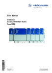
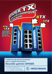
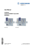
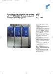
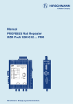
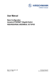
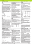
Description and Operating Instructions
Modular Industrial Communication
Equipment
MICE
Media modules
The Modular Industrial Communication Equipment, MICE, is a modular network component.
It was developed particularly for use in an industrial environment.
The media modules described in this instructions are the interface of the device to the LAN
and can be plugged onto the following basic
modules of the MICE switch:
– MS2108-2 (MICE 2000)
– MS3124-4 (MICE 3000)
– MS4128-5 (MICE 4000 / Power MICE)
– MS20-… and MS30-…
The MB20 expansion module allows you to
add 2 slots to the MS20-1600, MS30-1602,
MS3124-4, MS4128-5 MICE switch basic
module for installing media modules.
MM2-4TX1
MM2-2FXM3/2TX1
MM4-4TX/SFP
MM2-2FLM4
MM3-4TX5
MM2-2FXM2
MM2-2FXS2
The media modules are exclusively intended
for use with Hirschmann MS... modular switches.
MICE allows you to construct switched Industrial ETHERNET networks that conform to the
IEEE 802. and 802.3u standard using copper
wires or optical fibers in a bus or ring topology.
In the
– User manual “Installation“
– User manual “Basic configuration“
– User manual “Redundancy configuration“
– Reference manual “Web-based Interface“
– Reference manual “Command Line
Interface“
you will find a detailled description of the MICE
and further information.
MM3-2AUI
MM3-2FXM4/2TX1
MM3-2FXS2/2TX1
MM3-2FXM2/2TX1
MM3-1FXM2/3TX1
MM3-1FXL2/3TX1
MM3-1FXS2/3TX1
MM2-4FXM3
MB20 (old designation: MB2T) expansion module
Hirschmann. Simply a good Connection.
Document No. 039695001 Release 10 Date: 2012-02
MM3-4FXM2
MM3-4FXS2
MM3-4FXM4
MM3-4FLM4
The performance features described here are
binding only if they have been expressly guaranteed in the contract. We have checked that
the contents of the technical publication agree
with the hardware and software described.
However, it is not possible to rule out deviations completely, so we are unable to guarantee
complete agreement. However, the details in
the technical publication are checked regularly.
Any corrections which prove necessary are
contained in subsequent editions. We are grateful for suggestions for improvement.
We reserve the right to make technical modifications.
Permission is not given for the circulation or
reproduction of this document, its use or the
passing on of its contents unless granted
expressly. Contravention renders the perpetrator liable for compensation for damages. All
rights reserved, in particular in the case of
patent grant or registration of a utility or design.
Copyright
© Hirschmann
Automation and Control GmbH 2010
All Rights Reserved
Safety instructions
Housing
z
Warning!
The device may only be employed for
the purposes described in the catalog
and technical description, and only in
conjunction with external devices and
components recommended or approved by Hirschmann. The product can
only be operated correctly and safely if
it is transported, stored, installed and
assembled properly and correctly. Furthermore, it must be operated and serviced carefully.
Use in Hazardous Locations - Relevant for
North America
This equipment is suitable for use in Class I,
Division 2, Groups A, B, C and D harardous
locations - only for devices labeled accordingly
- OR non-hazardous locations. The temperature code is T4 (135 °C).
z
z
Warning!
EXPLOSION HAZARD - Do not disconnect equipment unless power has
been removed or the area is known to
be non-hazardous.
Warning!
EXPLOSION HAZARD - Substitution
of any components may impair suitablility for Class I, Division 2.
Supply voltage
To be supplied by a NEC Class 2 power
supply via MICE switch module.
For Power over Ethernet modules: Connect a
NEC Class 2 power supply only.
Use 60/75°C or 75°C copper (CU) wire only.
Shielding Ground
Note: The shielding ground of the connectable
twisted pairs lines is connected to the front
panel as a conductor.
□ Beware of possible short circuits when
connecting a cable section with conductive
shielding braiding.
2
Warning!
Only technicians authorized by
Hirschmann are permitted to open the
housing.
□ Make sure that the electrical installation
meets local or nationally applicable safety
regulations.
□ Peripheral equipment must be suitable for
the location in which it is used.
FCC note
This device complies with part 15 of the FCC
rules. Operation is subject to the following two
conditions:
(1) This device may not cause harmful interference, and
(2) this device must accept any interference
received, including interference that may
cause undesired operation.
These requirements are designed to provide
sufficient protection against interference when
the device is being used in a business environment. The device creates and uses high frequencies and can radiate same, and if it is not
installed and used in accordance with this operating manual, it can cause radio transmission
interference. The use of this device in a living
area can also cause interference, and in this
case the user is obliged to cover the costs of
removing the interference.
z
,
z
Warning!
Never insert pointed objects (thin screwdrivers, wires, etc.) into the inside of
the subrack! This especially applies to
the area behind the socket connectors.
Failure to ob-serve this point may
result in injuries caused by electric
shocks.
General Safety Instructions
□ Particular attention is to be paid to all warnings and items of information relating to
safety.
Certified usage
Please observe the following:
z
and in this case the operator may be
required to take appropriate measures.
The assembly guidelines provided in
these instructions must be strictly
adhered to in order to observe the
EMC threshold values.
Warning!
Any work that may have to be performed on the electrical installation
should be performed by fully qualified
technicians only.
Note: LED or LASER components in compliance with IEC 60825-1 (2007): CLASS 1 LASER
PRODUCT for Cat. No. having the following
fiber optic modules (identified by module code)
incorporated: S2, S4, E2, L2, G2, Z6, O7.
CLASS 1 LED PRODUCT for Cat. No. having
the following fiber optic modules (identified by
module code) incorporated: M2, M3, M4, F4.
Refer to the product code description in chapter 8.
ESD guidelines
The media modules contain components highly
sensitive to electrostatic fields.These components can be easily destroyed or have their
lives shortened by an electrical field or by a
discharge caused by touching the contacts.
You can find more informationen about devices
vulnerable to electrostatic fields in
IEC/TR 61340-5-2 (2007-08)
CE marking
The devices comply with the regulations contained in the following European directive(s):
2004/108/EG
Directive of the European Parliament and the
council for standardizing the regulations of
member states with regard to electromagnetic
compatibility.
In accordance with the above-named EU directive(s), the EU conformity declaration will be at
the disposal of the relevant authorities at the
following address:
Hirschmann Automation and Control GmbH
Stuttgarter Str. 45-51
72654 Neckartenzlingen
Tel.: +49 1805 141538
The product can be used in living areas (living
area, place of business, small business) and in
industrial areas.
– Interference immunity: EN 61000-6-2:2005
– Emitted interference: EN 55022:2006 +
A1:2007 Class A
z
Warning!
This is a class A device. This device
can cause interference in living areas,
Recycling note:
After its use, this product has to be
processed as electronic scrap and disposed of according to the prevailing
waste disposal regulations of your community / district / country / state.
For devices installed in explosive gas atmospheres according to ATEX directive 94/9/EC
Only intended for devices labeled accordingly
- refer to the device label (Fig. 0 - 2)
Conditions for safe use:
Must be mounted into a suitable certified IP 54
enclosure with tool removable cover.
x y
MM21
MICE Media Module
Product code - pos. 14:
temperature parameter: S or T or E
MM21-S2S2T1T1EBHH
The installer is to provide a transient protection
device to be set at a level not exceeding 40%
of the rated voltage at the power supply terminals of the apparatus.
INDUSTRIAL CONTROL EQUIPMENT Accessory
FOR USE IN HAZARDOUS LOCATIONS
E203960
CLASS I; DIV. 2
73RM
GROUPS A; B; C AND D
Also Listed as IND.CONT.EQ.
TEMPERATURE CODE T4
xx°C ... xxx°C
Ta:
E175531
71RN
WARNING - EXPLOSION HAZARD
/
c
For ambient temperatures below −10 °C and
above +60 °C use wiring suitable for both minimum and maximum ambient temperature.
Underlying norms and standards
EN 60079-0:
EN 60079-15:
2006 Explosive atmospheres
- Part 0: Equipment-General
Requirements
2005 Electrical equipment for
Explosive atmospheres
- Part 15: Equipment protec
tion by type of protection “n”
N13320
?U
8
II 3 G
Ex nA IIC T4
DEMKO
EM 06 ATEX 141499X
| A
IEC 61131-2
FCC CLASS A
DO NOT DISCONNECT EQUIPMENT
UNLESS POWER HAS BEEN
SWITCHED OFF OR THE AREA IS
KNOWN TO BE NON-HAZARDOUS.
AVERTISSEMENT - RISQUE D'EXPLOSION.
NE PAS DÉBRANCHER TANT QUE LE
CIRCUIT EST SOUS TENSION,
A MOINS QU'IL NE S'AGISSE D'UN
EMPLACEMENT NON DANGEREUX.
WARNING - EXPLOSION HAZARD
SUBSTITUTION OF COMPONENTS
MAY IMPAIR SUITABILITY FOR
CLASS I; DIVISION 2.
AVERTISSEMENT - RISQUE D'EXPLOSION LA SUBSTITUTION DES COMPOSANTS
PEUT RENDRE CE MATÉRIEL
INACCEPTABLE POUR LES
EMPLACEMENTS DE CLASSE I, DIVISION 2
TO BE SUPPLIED BY
A CLASS 2 POWER SUPPLY
OR ISOLATED LOW VOLTAGE
LIMITED ENERGY (LVLE).
DO NOT OPEN WHEN ENERGIZED
Max. surrounding air temperature xx°C
S/N: 999999999ZZSSNNNNN
DOM: WW/YYYY
Made in Germany
72654 Neckartenzlingen
Stuttgarter Str. 45-51
Hirschmann Automation and Control GmbH
Temperature code T4 for parameter S or T or E
Ta: 0 °C ... +60 °C for parameter S
Ta: -40 °C ... +70 °C for parameter T or E
Restriction to „MM30“ MICE Media Modules:
Ta: 0 °C ... +60 °C for parameter S or T or E
Temperature code T4 for parameter S or T or E
Max. surrounding air temperature 60 °C for parameter S
Max. surrounding air temperature 70 °C for parameter T or E
DOM - Date Of Manufacture
W: week
Y: year
Fig. 0: Equipment Label Markings (MICE Media Module)
Product code - pos. 7: temperature parameter: S or T or E
DOM - Date Of Manufacture
W: week
Y: year
Fig. 1: Equipment Label Markings (MB20)
Temperature code T4 for parameter S or T or E
Ta: 0 °C ... +60 °C for parameter S
Ta: -40 °C ... +70 °C for parameter T or E
Temperature code T4 for parameter S or T or E
Fig. 2: Equipment Label Markings
3
1. MICE Hardware
2. Functional description
1.1 SWITCH BASIC MODULES
The documentation enclosed to the switch
basic module gives you a detailed description
of the switch basic modules:
– „User Manual Installation
Industrial ETHERNET Switch MICE
MS20/MS30” for MS20-… and MS30-…
– „User Manual Installation
Industrial ETHERNET Switch Power MICE”
– “Description and Operating Instructions Industrial ETHERNET Modular Industrial Communication Equipment MICE/Power MICE”
for
– MS2108-2 (MICE 2000)
– MS3124-4 (MICE 3000)
The ports of a MICE represent a terminal
connection for the connected LAN segment.
You can connect single devices or complete
network segments.
1.2 MEDIA MODULES
– MICE 2000: See Table 1.
– MICE 3000: See Table 2.
– MICE 4000: See Table 3.
– MICE media modules open variant:
See Table 4.
1.3 MB20 (OLD DESIGNATION: MB-2T)
EXPANSION MODULE
The MB20 expansion module allows you to
add 2 slots to the MS20-1600, MS30-1602,
MS3124-4, MS4128-5 MICE switch basic
module for installing media modules.
1.4 SFP MODULES
SFP modules are optical transceivers
(Fast ETHERNET and Gigabit ETHERNET
SFP modules see chapter 7 Technical Data).
The SFP modules are plugged into the SFP
slots of the Fast ETHERNET media module
MM3-4SFP (MM20-Z6Z6Z6Z6) or of the
Gigabit ETHERNET media modules
MM4-4TX/SFP / MM4-2TX/SFP to provide a
F/O port.
The MM3-4SFP (MM20-Z6Z6Z6Z6) has four
slots for SFP modules (100 Mbit/s).
The MM4-4TX/SFP / MM4-2TX/SFP has
four/two TP interfaces and four/two slots for
SFP modules (100/1000 Mbit/s). Inserting the
SFP module deactivates the corresponding TP
interface.
1.5 MM22-T1T1T1T1
POE MEDIA MODULE
The MM22-T1T1T1T1 PoE media module
(deeper module style) supports Power over
ETHERNET (PoE) in compliance with IEEE
802.3af. It enables the connection and the
remote supply of e.g. IP telephones (voice over
IP), webcams, sensors, print servers and
WLAN access points via 10BASE-T/100BASETX. With PoE, the power supply of these data
terminal equipments is served via the twisted
pair cable.
The MM22-T1T1T1T1 media module offers
four 10BASE-T/100BASE-TX ports (RJ45
connectors) for connecting network segments
or PoE data terminal equipments (PD, Powered Device) up to class 0 (respectively class 3)
maximum.
The current is supplied on the idle wire pairs
(spare pairs); the ports are not electrically isolated against each other.
In compliance with IEEE 802.3af, each port
has the attributes:
– Endpoint PSE
– Alternative B.
4
2.1 INTERFACES
TP/TX/FL/FX terminal devices or other
TP/TX/FL/FX segments can be connected to
the 10/100/1000 Mbit/s ports of the media
modules.
The MICE and MS20 supports both ETHERNET 10 Mbit/s and Fast ETHERNET 100
Mbit/s, the Power MICE and MS30 supports
additionally Gigabit ETHERNET 1000 Mbit/s.
The TP/TX ports support autocrossing, autonegotiation and autopolarity.
2.2 DIP SWITCH (MM3-AUI)
With the 3-pin DIP switch on the MM3-2AUI
module
– you can switch on or off the SQE test function at port 1 with the SQE-Test Port 1
switch.
State of delivery: switch in position 0 (Off),
i.e. SQE test function not active.
– you can switch on or off the SQE test function at port 2 with the SQE-Test Port 2
switch.
State of delivery: switch in position 0 (Off),
i.e. SQE test function not active.
– you can switch on or off the monitoring of
the DTE voltage, for both ports together,
with the DTEPower-Monitor switch.
– ON: monitoring of the DTE voltage active,
data transmission only possible if DTE voltage available.
– OFF: no monitoring of the DTE voltage,
data transmission always possible.
– State of delivery: switch in position 0
(OFF), i.e. no monitoring of DTE
voltage.
3. Assembly, startup procedure
and dismantling
3.1 UNPACKING, CHECKING
□ Check whether the package was delivered
completely (see scope of delivery).
□ Check the individual parts for transport
damage.
z
Warning!
Use only undamaged parts!
3.2 ASSEMBLING MEDIA MODULES
Media modules can be assembled and disassembled during running operation.
□ To fasten a media module, first remove the
protective cap over the plug of the MICE.
□ Plug the media module onto the plug.
□ Tighten the 4 screws on the corners of the
media module.
□ Check whether the switch pre-setting suits
your requirements.
□ Fit the signal lines.
3.3 ASSEMBLING SFP MODULES
□ To fasten a SFP module, first remove the
protective cap over the socket.
□ Insert the SFP module with the closed lock
into the socket until you hear it snap in.
Note: Use only Hirschmann SFP modules.
3.4 ASSEMBLING THE MB20
EXPANSION MODULE
The MB20 expansion module can be
installed while in running operation.
□ On the right side of the switch basic module, loosen the screw at the top and at the
bottom (1-3 revolutions).
□ Remove the side cover.
□ If you have not yet done so, mount the
switch basic module onto the top-hat rail.
□ Slide the MB20 expansion module on the
top-hat rail toward the switch basic module
until the modules plug into each other.
□ On the switch basic module, tighten the
screws at the top and at the bottom.
3.5 STARTUP PROCEDURE
You start up the MICE by connecting the supply
voltage via the terminal block(s) on the MICE
basic module. Lock the terminal block(s).
3.6 CONNECTING THE
MM22-T1T1T1T1 POE MEDIA MODULE
The MM22-T1T1T1T1 PoE media module is
supplied with the PoE voltage (48 V DC safety
extra-low voltage) via an external power supply
unit. The PoE voltage is fed into the 3-pin terminal block of the PoE media module. The twisted pair cables are supplied with the PoE voltage on port 1 to 4 via the spare pairs (pins 4&5
and 7&8 of the RJ45 sockets).
Note: Only use the Hirschmann
RPS60/48V EEC power supply unit for providing the PoE voltage.
□ Make sure that the external power
supply unit being used for providing the
PoE voltage meets, among other things,
the following requirements:
– Isolation requirements in compliance with
IEEE 802.3af (electrical strength of the
48V output to “rest of the world" 2250 V
DC for 1 min.)
– Output power < 100 W.
– Current limiting < 2 A.
– Power supply unit and PoE media module form a "Limited Power Source" in compliance with IEC60950-1.
– The external PoE power supply unit has
to be able to provide the power for the
PDs being connected.
All these conditions are met by the
RPS60/48V EEC power supply unit.
□ Connect the PoE voltage to the 3-pin
terminal block (included in the scope of
delivery), as shown in the following figure.
Make sure that your installation complies
with the following conditions:
– Length of the supply line < 3 m.
– Cross-section of the supply lines is
dimensioned for 1.5 A
+
48 V -
Fig. 3: 3-pin terminal block of the
PoE media module
□ Mount the terminal block for the PoE supply voltage on the bottom side of the PoE
module via snap lock. Push it until it locks
into position.
Note: Use 4-pair twisted pair cables for
connecting the data terminal equipments.
Only connect data terminal equipments which
are conform to IEEE 802.3af.
5. Technical data
Dimensions W x H x D
38 mm x 110 mm x 79 mm (MM2-...)
38 mm x 110 mm x 119 mm (MM3-..., MM4-...)
38 mm x 110 mm x 79 bzw. 119 mm (MM20-..., MM21-..., MM22-..., MM23-..., MM30-..., MM33-...)
Humidity
Atmospheric pressure
Pollution degree
Laser protection
Protection type
EMV interference proof
EN 61000-4-2, Discharge of static electricity
10% to 95% (non condensing)
up to 2000 m (795 hPa, higher altitudes on demand)
2
Class 1 conforming to EN 60825-1: 2007
IP 20
A 1)
Contact discharge: test level 3
4 kV
Air discharge: test level 3
8 kV
Test level 3 (80 - 2000 MHz)
10 V/m
- Power line
2 kV
- Data line
1 kV
- Power line, line/line: test level 2
0,5 kV
- Power line, line/earth: test level 3
1 kV
- Data line: test level 3
1 kV
10 kHz - 150 kHz
3V
150 kHz - 80 MHz
10 V
Test level 4
-
EN 61000-4-3, Electromagnetic fields
EN 61000-4-4, Fast transients (burst),
Test level 3, x
EN 61000-4-5 Surge voltage
EN 61000-4-6 Cable-based RF faults,
Test level 3
EN 61000-4-9 Impulse shaped magnetic fields
EMV emitted immunity
EN 55022
FCC 47 CFR Part 15
German Lloyd
Stability
Vibration
IEC 60068-2-6
German Lloyd
B 1)
8 kV
15 kV
20 V/m
4 kV
4 kV
1 kV
2 kV
4 kV
3V
10 V
300 A/m
H 1)
8 KV
15 kV
20 V/m
4 kV
4 kV
1 kV
2 kV
4 kV
3V
10 V
300 A/m
A 1)
Class A
Yes
Class A
Yes
Rules for Classifikation and Construction VI-7-3 - Yes
Part 1 Ed. 2001
B 1)
Yes
Yes
Yes
H 1)
Yes
Yes
Test FC, test level in line with IEC 61131-2V
Guidelines for the Performance
of Type Tests Part 1
Normal Installation in line with EN 61850-3
Test Ea, test level in line with IEC 61131-2
Normal Installation in line with EN 61850-3
Yes
-
Yes
Yes
Yes
Yes
Yes
-
Yes
Yes
Yes
Yes
Yes
Yes
IEC 870-2-2 Table 3
IEC 60068-2-27
IEC 870-2-2 Table 3
1) Product code A: Certification = CE, UL
Product code B: Certification = CE, UL, GL, Railway (along track), Substation, ATEX
Product code H: Certification = CE, UL, GL, Railway (along track), Substation
The media modules in Table 1 to 3 (see page 5) have the certification “A”.
Shock
Network size
AUI port
Length of a AUI cable
TP/TX port 10/100/1000BASE-T/TX
Length of a twisted pair segment
F/O port 10BASE-FL
Product code Wave length
-M4
MM
850 nm
-M4
MM
850 nm
50 m max.
100 m (328 ft) max. (cat5e cable with 1000BASE-T)
Fiber
50/125 µm
62.5/125 µm
System attenuation
0-9.5 dB
0-12.5 dB
F/O port 100BASE-FX
Product code
Wave length
Fiber
System attenuation
-M2, -M4
MM
1300 nm
50/125 µm
0-8 dB
-M2, -M4
MM
1300 nm
62.5/125 µm
0-11 dB
-S2
SM
1300 nm
9/125 µm
0-16 dB
-L2
LH
1550 nm
9/125 µm
7-29 dB
-P9
MM POF 650 nm
980/1000 µm
0-14.0 dB
-G2
LH+
1550 nm
9/125 µm
14-47 dB
F/O port 100BASE-FX (SFP Fiberoptic Fast ETHERNET Transceiver)
Product code
Wave length
Fiber
System attenuation
M-FAST-SFP-...
-MM/LC (EEC) MM
1310 nm
50/125 µm
0-11 dB
-MM/LC (EEC) MM
1310 nm
62.5/125 µm
0-8 dB
-SM/LC (EEC) SM
1310 nm
9/125 µm
0-13 dB
-SM+/LC (EEC) SM
1310 nm
9/125 µm
10-29 dB
-LH/LC
SM
1550 nm
9/125 µm
10-29 dB
F/O port 1000BASE-FX (SFP Fiberoptic Gigabit ETHERNET Transceiver)
Product code Wave length
Fiber
System attenuation
M-SFP-...
-SX/LC (EEC) MM
850 nm
50/125 µm
0-7.5 dB
850 nm
62.5/125 µm
0-7.5 dB
-SX/LC (EEC) MM
-MX/LC
MM
1310 nm
50/125 µm
0-8 dB
-MX/LC
MM
1310 nm
62,5/125 µm
0-8 dB
-LX/LC (EEC) SM
1310 nm 1)
50/125 µm
0-11 dB
1)
1310 nm
62.5/125 µm
0-11 dB
-LX/LC (EEC) SM
Expansion
0-2,000 m
0-3,000 m
Fiber data
3.0 dB/km; 400 MHz*km
3.2 dB/km; 200 MHz*km
Expansion
0-5 km
0-4 km
0-30 km
24-86 km
0-55 m
67-176 km
Fiber data
1.0 dB/km; 800 MHz*km
1.0 dB/km; 500 MHz*km
0.4 dB/km; 3.5 ps/(nm*km)
0.3 dB/km; 19 ps/(nm*km)
200 dB/km; 10 MHz*km
0.25 dB/km; 19 ps/(nm*km)
Expansion
Fiber data
0-5 km
0-4 km
0-25 km
25-65 km
40-104 km
1.0 dB/km; 800 MHz*km
1.0 dB/km; 500 MHz*km
0.4 dB/km; 3.5 ps/(nm*km)
0.4 dB/km; 3.5 ps/(nm*km)
0.25 dB/km; 19 ps/(nm*km)
Expansion
Fiber data
0-550 m
0-275 m
2 km
1 km
0-550 m
0-550 m
3.0 dB/km; 400 MHz*km
3.2 dB/km; 200 MHz*km
1.0 dB/km, 500 MHz*km
1.0 dB/km, 500 MHz*km
1.0 dB/km; 800 MHz*km
1.0 dB/km; 500 MHz*km
5
-LX/LC (EEC)
-LX+/LC (EEC)
-LH/LC (EEC)
-LH+/LC
SM
SM
LH
LH
1310 nm
1310 nm
1550 nm
1550 nm
9/125 µm
9/125 µm
9/125 µm
9/125 µm
0-11 dB
5-20 dB
6-22 dB
15-32 dB
0-20 km
14-42 km
24-72 km
60-120 km
0.4 dB/km; 3.5 ps/(nm*km)
0.4 dB/km; 3.5 ps/(nm*km)
0.25 dB/km; 19 ps/(nm*km)
0.25 dB/km; 19 ps/(nm*km)
MM = multimode, SM = singlemode, LH = singlemode longhaul
1) with F/O adapter in line with IEEE802.3-2002 clause 38 (single-mode fiber offset-launch mode conditioning patch cord)
Displays
Device status
Port status
1 x green LED
P – Power, internal supply voltage present
4 x green/yellow LED 1 to 4 – The meaning depends on the setting of the display status.
Controls (MM3-2AUI)
3-pole DIP switch
1 – SQE-Test Port 1 – ON = SQE test function on port 1 enabled
2 – SQE-Test Port 2 – ON = SQE test function on port 2 enabled
3 – DTEPower-Monitor – ON = Monitoring of the DTE voltage active
Scope of delivery
MICE media module incl.
Labels, description and operating instructions
Accessories
Pocket Guide
AutoConfigurationAdapter ACA 11
Terminal access cable
6-pin terminal block (50 pieces)
Rail Power Supply RPS 30
Rail Power Supply RPS 80 EEC
Rail Power Supply RPS 120 EEC
Rail Power Supply RPS60/48V EEC
Network Management Software HiVision
Network Management Software Industrial HiVision
280 720-851
943 751-001
943 301-001
943 845-002
943 662-003
943 662-080
943 662-120
943 952-001
943 471-100
943 156-xxx
6. MICE media modules
6.1 PORT ASSIGNMENT (EXAMPLES)
MM4-4TX/SFP
1
1
1
2
2
2
1
3
4
3
3
2
3
1* 2*
4
4
4
MM3-4SFP (MM20-Z6Z6Z6Z6)
3* 4*
1
2
3
MM20-Z6Z6Z6Z6
MM3-4FLM4
Port 1 to 4 (SFP ports) alternatively to port 1* to 4* (TP ports)
MM2-4FXM3
4
6.2 NUMBER AND KIND OF MEDIA CONNECTORS
MICE 2000 media modules
Module type
AUI port
MM2-4TX1(-EEC)
MM2-2FLM4
MM2-4FXM3
MM2-2FXM3/2TX1
MM2-2FXM2
MM2-2FXS2
–
–
–
–
–
–
TP ports
10/100
F/O port
multimode
10 Mbit/s
4, RJ45
–
–
2, RJ45
–
–
–
2, ST
–
–
–
–
F/O port
multimode
POF
100 Mbit/s
–
–
–
–
–
–
F/O port
multimode
100 Mbit/s
–
–
4, MTRJ
2, MTRJ
2, DSC
–
F/O port
singlemode
1300 nm,
100 Mbit/s
–
–
–
–
–
2, DSC
F/O port
singlemode
1550 nm,
100 Mbit/s
–
–
–
–
–
–
Supported since
MICE SW release
Power MS20
MICE MICE MS30
1.0
1.0 1.0
1.0
1.0 1.0
1.0
1.0 1.0
1.0
1.0 1.0
1.0
1.0 1.0
2.0
1.0 1.0
F/O port
singlemode
1550 nm,
100 Mbit/s
–
–
Supported since
MICE SW release
Power MS20
MICE MICE MS30
4.0
1.0 1.0
4.0
1.0 1.0
Table 1: Number of media connectors each MICE 2000 media module, kind of connector and necessary software
MICE 3000 media modules
Module type
AUI port
MM3-2AUI
MM3-4TX5
6
TP ports
10/100
2, Sub-D-St. –
–
4, M12
F/O port
multimode
10 Mbit/s
–
–
F/O port
multimode
POF
100 Mbit/s
–
–
F/O port
multimode
100 Mbit/s
–
–
F/O port
singlemode
1300 nm,
100 Mbit/s
–
–
MM3-4TX1-RT 1)
MM3-2FLM4/2TX1-RT 1)
MM3-4FLM4
MM3-1FXM2/3TX1
MM3-2FXM2/2TX1(-EEC)
MM3-2FXM2/2TX1-RT 1)
MM3-2FXM4/2TX1
MM3-4FXM2
MM3-4FXM4
MM3-1FXS2/3TX1(-EEC)
MM3-2FXS2/2TX1
MM3-2FXS2/2TX1-RT 1)
MM3-4FXS2
MM3-1FXL2/3TX1
–
–
–
–
–
–
–
–
–
–
–
–
–
–
4, RJ45
2, RJ45
–
3, RJ45
2, RJ45
2, RJ45
2, RJ45
–
–
3, RJ45
2, RJ45
2, RJ45
–
3, RJ45
–
2, ST
4, ST
–
–
–
–
–
–
–
–
–
–
–
–
–
–
–
–
–
–
–
–
–
–
–
–
–
–
–
–
1, DSC
2, DSC
2, DSC
2, ST
4, DSC
4, ST
–
–
–
–
–
–
–
–
–
–
–
–
–
–
1, DSC
2, DSC
2, DSC
4, DSC
–
–
–
–
–
–
–
–
–
–
–
–
–
–
1, DSC
5.0
5.0
2.0
3.1
2.0
5.0
3.1
2.0
3.1
3.1
2.0
5.0
3.1
2.0
2.0
2.0
1.0
1.0
1.0
2.0
1.0
1.0
1.0
1.0
1.0
2.0
1.0
1.0
1.0
1.0
1.0
1.0
1.0
1.0
1.0
1.0
1.0
1.0
1.0
1.0
1.0
1.0
Table 2: Number of media connectors each MICE 3000 media module, kind of connector and necessary software
1) Realtime modules, in line with IEEE 1588 PTP (Precision Time Protocol Version 2)
MICE 4000 media modules
Module type
TP ports
10/100/1000
MM4-2TX/SFP
MM4-4TX/SFP
SFP ports
alternativ zu TP-Ports/
alternatively to TP ports
2, RJ45
4, RJ45
Supported since
MICE SW release
Power MS20
MICE MICE MS30
–
2.0
1.0
–
1.0
1.0
2
4
Table 3: Number of media connectors each MICE 4000 media module, kind of connector and necessary software
Open variant media modules
Module type
TP ports
10/100/1000
MM20..., MM21..., MM30...
MM22-T1T1T1T1
MM20-Z6Z6Z6Z6
MM20-P9P9P9P9
MM20-P9P9T1T1
MM23-T1T1T1T1...SAHH1)
MM23-M2M2T1T1...SAHH1)
MM23-S2S2T1T1...SAHH1)
MM23-F4F4T1T1...SAHH1)
MM33-O7O79999...SAHH1)
SFP ports
alternativ zu TP-Ports/
alternatively to TP ports
0 to 4 ports (media and connector at your option, see chapter 8 “Open Variant”)
4 ports (twisted pair, RJ45 connector)
4 ports (fiber optic, SFP slot, 100 Mbit/s)
4 ports (fiber optic, SCRJ connector, 100 Mbit/s)
4 ports (2 x fiber optic, SCRJ connector, 100 Mbit/s; 2 x twisted pair, RJ45 connector)
4 ports (twisted pair, RJ45 connector)
4 ports (2 x multimode FX, duplex SC connector, 100 Mbit/s; 2 x twisted pair, RJ45 connector)
4 ports (2 x singlemode FX, duplex SC connector, 100 Mbit/s; 2 x twisted pair, RJ45 connector)
4 ports (2 x multimode FL, ST connector, 10 Mbit/s; 2 x twisted pair, RJ45 connector)
2 ports (2 x combo ports twisted pair RJ45 or alternatively SFP slot, 1000 Mbit/s)
Supported since
MICE SW release
Power MS20
MICE MICE MS30
–
–
2.0
–
3.0
3.0
–
4.0
4.0
–
4.2
4.2
–
4.2
4.2
–
5.0
5.0
–
5.0
5.0
–
5.0
5.0
–
5.0
5.0
–
5.0
5.0
Table 4: MICE open variant media module, necessary software
1) Realtime modules, in line with IEEE 1588 PTP (Precision Time Protocol Version 2)
6.3 PIN ASSIGNMENT OF THE INTERFACES
10/100 Mbit/s twisted pair connection
n.c.
n.c.
TDn.c.
n.c.
TD+
RDRD+
Pin 8
Pin 7
Pin 6
Pin 5
Pin 4
Pin 3
Pin 2
Pin 1
Fig. 4: Pin assignment of a TP/TX interface in
MDI-X mode, RJ45 socket
TD+
1
2
RD+
RD-
4
3
TD-
Fig. 5: Pin assignment of a TP/TX interface,
M12 socket
10/100 Mbit/s twisted pair connection
PoE (Power over Ethernet) at
MM22-T1T1T1T1 PoE media module
VVTDV+
V+
TD+
RDRD+
Pin 8
Pin 7
Pin 6
Pin 5
Pin 4
Pin 3
Pin 2
Pin 1
Fig. 6: Pin assignment of a TP/TX interface
with PoE, for supply via the the idle wire pairs
(spare pairs), RJ45 socket
3-pin terminal block (PoE module)
+
10/100/1000 Mbit/s twisted pair connection
BI_DCBI_DC+
BI_DABI_DDBI_DD+
BI_DA+
BI_DBBI_DB+
Pin 8
Pin 7
Pin 6
Pin 5
Pin 4
Pin 3
Pin 2
Pin 1
Fig. 8: Pin assignment of the 1000 Mbit/s twisted pair interface
AUI connection
shielding CO
n.c.
GND
output DI-A
shielding DI
input DO-A
output CI-A
shielding CI
Pin 8
Pin 7
Pin 6
Pin 5
Pin 4
Pin 3
Pin 2
Pin 1
Pin 15
Pin 14
Pin 13
Pin 12
Pin 11
Pin 10
Pin 9
n.c.
shielding 12 V
voltage 12 V
output DI-B
shielding DO
input DO-B
output CI-B
48 V -
Fig. 7: 3-pin terminal block of the
PoE media module
Fig. 9: Pin assignment of the AUI interface
7
7. General data
Power
consumption
8
Power
output
Operating temp.
surrounding air
Storage
temperature
Order
number
MICE 2000 media modules:
MM2-4TX1
MM2-4TX1-EEC
MM2-4FXM3
MM2-2FXM3 / 2TX1
MM2-2FXM2
MM2-2FXS2
0.8 W
0.8 W
6.8 W
3.8 W
3.8 W
3.8 W
2.8 Btu (IT)/h
2.8 Btu (IT)/h
23.2 Btu (IT)/h
13.0 Btu (IT)/h
13.0 Btu (IT)/h
13.0 Btu (IT)/h
0 °C … +60 °C
−40 °C … +70 °C
0 °C … +60 °C
0 °C … +60 °C
0 °C … +60 °C
0 °C … +60 °C
−40 °C … +70 °C
−40 °C … +85 °C
−40 °C … +70 °C
−40 °C … +70 °C
−40 °C … +70 °C
−40 °C … +70 °C
943 722-101
943 722-151
943 721-101
943 720-101
943 718-101
943 719-101
MICE 3000 media modules:
MM3-2AUI
MM3-4FLM4
MM3-2FLM4 / 2TX1-RT
MM3-4TX5
MM3-4TX1-RT
MM3-1FXM2 / 3TX1
MM3-1FXM2 / 3TX1-EEC
MM3-2FXM2 / 2TX1
MM3-2FXM2 / 2TX1-EEC
MM3-2FXM2 / 2TX1-RT
MM3-2FXM4 / 2TX1
MM3-4FXM2
MM3-4FXM4
MM3-1FXS2 / 3TX1
MM3-1FXS2 / 3TX1 EEC
MM3-2FXS2 / 2TX1
MM3-2FXS2 / 2TX1-EEC
MM3-2FXS2 / 2TX1-RT
MM3-4FXS2
MM3-1FXL2 / 3TX1
MM3-4SFP
3.4 W
5.0 W
5.0 W
0.8 W
0.8 W
2.3 W
2.3 W
3.8 W
3.8 W
3.8 W
3.8 W
6.8 W
6.8 W
2.3 W
2.3 W
3.8 W
3.8 W
3.8 W
6.8 W
3.4 W
8.0 W
11.6 Btu (IT)/h
17.1 Btu (IT)/h
17.1 Btu (IT)/h
2.8 Btu (IT)/h
2.8 Btu (IT)/h
7.9 Btu (IT)/h
7.9 Btu (IT)/h
13.0 Btu (IT)/h
13.0 Btu (IT)/h
13.0 Btu (IT)/h
13.0 Btu (IT)/h
23.2 Btu (IT)/h
23.2 Btu (IT)/h
7.9 Btu (IT)/h
7.9 Btu (IT)/h
13.0 Btu (IT)/h
13.0 Btu (IT)/h
13.0 Btu (IT)/h
23.2 Btu (IT)/h
11.6 Btu (IT)/h
27.3 Btu (IT)/h
0 °C … +60 °C
0 °C … +60 °C
0 °C … +60 °C
0 °C … +60 °C
0 °C … +60 °C
0 °C … +60 °C
−40 °C … +70 °C
0 °C … +60 °C
−40 °C … +70 °C
0 °C … +60 °C
0 °C … +60 °C
0 °C … +60 °C
0 °C … +60 °C
0 °C … +60 °C
−40 °C … +70 °C
0 °C … +60 °C
−40 °C … +70 °C
0 °C … +60 °C
0 °C … +60 °C
0 °C … +60 °C
0 °C … +60 °C
−40 °C … +70 °C
−40 °C … +70 °C
−40 °C … +70 °C
−40 °C … +70 °C
−40 °C … +70 °C
−40 °C … +70 °C
−40 °C … +85 °C
−40 °C … +70 °C
−40 °C … +85 °C
−40 °C … +70 °C
−40 °C … +70 °C
−40 °C … +70 °C
−40 °C … +70 °C
−40 °C … +70 °C
−40 °C … +85 °C
−40 °C … +70 °C
−40 °C … +85 °C
−40 °C … +70 °C
−40 °C … +70 °C
−40 °C … +70 °C
−40 °C … +70 °C
943 840-101
943 760-101
943 117-004
943 841-101
943 117-001
943 839-101
943 839-151
943 761-101
943 761-151
943 117-002
943 837-101
943 764-101
943 835-101
943 838-101
943 838-151
943 762-101
943 762-151
943 117-003
943 836-101
943 763-101
943 938-001
MICE 4000 media modules:
MM4-4TX / SFP
MM4-2TX / SFP
9.0 W
5.8 W
30.8 Btu (IT)/h
19.8 Btu (IT)/h
0 °C … +60 °C
0 °C … +60 °C
−40 °C … +70 °C
−40 °C … +70 °C
943 010-001
943 622-001
Open variant media modules (You will find further informationen on www.hirschmann.com):
MM20-... 4 TX-/0 FX-Ports
0.8 W
2.8 Btu (IT)/h
see chapter 8
MM20-... 3 TX-/1 FX-Ports
2.3 W
7.9 Btu (IT)/h
see chapter 8
MM20-... 2 TX-/2 FX-Ports
3.8 W
13.0 Btu (IT)/h
see chapter 8
MM20-... 0 TX-/2 FX-Ports
3.8 W
13.0 Btu (IT)/h
see chapter 8
MM20-... 1 TX-/3 FX-Ports
5.3 W
18.1 Btu (IT)/h
see chapter 8
MM20-... 0 TX-/4 FX-Ports
6.8 W
23.2 Btu (IT)/h
see chapter 8
MM20-A8A89999
3.4 W
11.6 Btu (IT)/h
see chapter 8
MM20-F4F4F4F4
5.0 W
17.1 Btu (IT)/h
see chapter 8
MM20-Z6Z6Z6Z6
8.0 W
27.3 Btu (IT)/h
see chapter 8
MM20-P9P9P9P9SAHH
8.0 W
27.3 Btu (IT)/h
0 °C ... +60 °C
MM20-P9P9T1T1SAHH
5.2 W
17.8 Btu (IT)/h
0 °C ... +60 °C
MM30-O7O7O7O7
9.0 W
30.8 Btu (IT)/h
see chapter 8
MM30-O7O79999
5.8 W
19.8 Btu (IT)/h
see chapter 8
MM21-T1T1T1T1
0.8 W
2.8 Btu (IT)/h
see chapter 8
MM21-F4F4T1T1
5.0 W
17.1 Btu (IT)/h
see chapter 8
MM21-M2M2T1T1
3.8 W
13.0 Btu (IT)/h
see chapter 8
MM21-S2S2T1T1
3.8 W
13.0 Btu (IT)/h
see chapter 8
MM22-T1T1T1T1
0.8 W
2.8 Btu (IT)/h
see chapter 8
MM23-T1T1T1T1...SAHH
4.5 W
15.4 Btu (IT)/h
0 °C ... +60 °C
MM23-M2M2T1T1...SAHH
6.0 W
20.5 Btu (IT)/h
0 °C ... +60 °C
MM23-S2S2T1T1...SAHH
5.5 W
18.8 Btu (IT)/h
0 °C ... +60 °C
MM23-F4F4T1T1...SAHH
5.5 W
18.8 Btu (IT)/h
0 °C ... +60 °C
MM33-O7O79999...SAHH
7.5 W
25.6 Btu (IT)/h
0 °C ... +60 °C
see chapter 8
see chapter 8
see chapter 8
see chapter 8
see chapter 8
see chapter 8
see chapter 8
see chapter 8
see chapter 8
−40 °C ... +70 °C
−40 °C ... +70 °C
see chapter 8
see chapter 8
see chapter 8
see chapter 8
see chapter 8
see chapter 8
see chapter 8
−40 °C ... +70 °C
−40 °C ... +70 °C
−40 °C ... +70 °C
−40 °C ... +70 °C
−40 °C ... +70 °C
product code; chap. 8
product code; chap. 8
product code; chap. 8
product code; chap. 8
product code; chap. 8
product code; chap. 8
product code; chap. 8
product code; chap. 8
product code; chap. 8
product code; chap. 8
product code; chap. 8
product code; chap. 8
product code; chap. 8
product code; chap. 8
product code; chap. 8
product code; chap. 8
product code; chap. 8
product code; chap. 8
product code; chap. 8
product code; chap. 8
product code; chap. 8
product code; chap. 8
product code; chap. 8
Expansion moduel
MB20
0W
0 Btu (IT)/h
0 °C … +60 °C
−40 °C … +70 °C
943 733-002
Fast ETHERNET SFP modules:
M-FAST SFP-MM / LC
M-FAST SFP-MM / LC EEC
M-FAST SFP-SM / LC
M-FAST SFP-SM / LC EEC
M-FAST SFP-SM+ / LC
M-FAST SFP-SM+ / LC EEC
M-FAST SFP-LH / LC
0W
0W
0W
0W
0W
0W
0W
0 Btu (IT)/h
0 Btu (IT)/h
0 Btu (IT)/h
0 Btu (IT)/h
0 Btu (IT)/h
0 Btu (IT)/h
0 Btu (IT)/h
0 °C … +60 °C
−40 °C … +70 °C
0 °C … +60 °C
−40 °C … +70 °C
0 °C … +60 °C
−40 °C … +70 °C
0 °C … +60 °C
−40 °C … +70 °C
−40 °C … +85 °C
−40 °C … +70 °C
−40 °C … +85 °C
−40 °C … +70 °C
−40 °C … +85 °C
−40 °C … +70 °C
943 865-001
943 945-001
943 866-001
943 946-001
943 867-001
943 947-001
943 868-001
Gigabit ETHERNET SFP modules:
M-SFP-SX / LC
0W
M-SFP-SX / LC EEC
0W
M-SFP-MX / LC
0W
M-SFP-LX / LC
0W
M-SFP-LX / LC EEC
0W
M-SFP-LH / LC
0W
M-SFP-LH / LC EEC
0W
M-SFP-LH+ / LC
0W
M-SFP-LH+ / LC EEC
0W
M-SFP-LH+ / LC
0W
0 Btu (IT)/h
0 Btu (IT)/h
0 Btu (IT)/h
0 Btu (IT)/h
0 Btu (IT)/h
0 Btu (IT)/h
0 Btu (IT)/h
0 Btu (IT)/h
0 Btu (IT)/h
0 Btu (IT)/h
Bidirectional Gigabit ETHERNET SFP modules:
M-SFP-BIDI Type A LX/LC EEC 0 W
0 Btu (IT)/h
M-SFP-BIDI Type B LX/LC EEC 0 W
0 Btu (IT)/h
M-SFP-BIDI Type A LX/LC EEC 0 W
0 Btu (IT)/h
M-SFP-BIDI Type B LX/LC EEC 0 W
0 Btu (IT)/h
M-SFP-BIDI Bundle LX/LC EEC 0 W
0 Btu (IT)/h
(Type A + B)
M-SFP-BIDI Bundle LX/LC EEC 0 W
0 Btu (IT)/h
(Type A + B)
0 °C … +60 °C
−40 °C … +70 °C
0 °C … +60 °C
0 °C … +60 °C
−40 °C … +70 °C
0 °C … +60 °C
−40 °C … +70 °C
0 °C … +60 °C
−40 °C … +70 °C
0 °C … +60 °C
−40 °C … +70 °C
−40 °C … +85 °C
−40 °C … +70 °C
−40 °C … +70 °C
−40 °C … +85 °C
−40 °C … +70 °C
−40 °C … +85 °C
−40 °C … +70 °C
−40 °C … +85 °C
−40 °C … +70 °C
943 014-001
943 896-001
942 035-001
943 015-001
943 897-001
943 042-001
943 898-001
942 023-001
942 024-001
943 049-001
−40 °C … +70 °C
−40 °C … +70 °C
−40 °C … +70 °C
−40 °C … +70 °C
−40 °C … +70 °C
−40 °C … +85 °C
−40 °C … +85 °C
−40 °C … +85 °C
−40 °C … +85 °C
−40 °C … +85 °C
943 974-001
943 974-002
943 975-001
943 975-002
943 974-101
−40 °C … +70 °C
−40 °C … +85 °C
943 975-101
8. Open variant product code
Alternatively to the order number (ref. table in
chapter 7, last column) you can use the product code. It offers you, tailored to your requirements, an additional variety of media module
types.
The product code of your media module is
made from combining the desired product characteristics in accordance with the following
table. The short designation is in column
“Ident.”.
Position
1 to 4
Ident.
MM20
MM21
MM22
MM23
MM30
MM33
Feature
Media module 10/100 Mbit/s (standard)
Media module 10/100 Mbit/s (PTP Version 2)
Media module 10/100 Mbit/s (Power over Ethernet)
Media module 10/100 Mbit/s (PTP Version 2)
Media module 1000 Mbit/s (standard)
Media module 1000 Mbit/s (PTP Version 2)
T1
T5
M2
M3
M4
S2
S4
L2
G2
F4
P9
O7
A8
Z6
Twisted pair (TX) / RJ45
Twisted pair (TX) / M12
Multimode FX DSC (100 Mbit/s)
Multimode FX MTRJ (100 Mbit/s)
Multimode FX ST (100 Mbit/s)
Singlemode FX DSC (100 Mbit/s)
Singlemode FX ST (100 Mbit/s)
Singlemode longhaul FX DSC (100 Mbit/s)
Singlemode longhaul FX DSC 200km (100 Mbit/s)
Multimode FL ST (10 Mbit/s)
POF FX SCRJ (100Mbit/s)
Combo port gigabit Ethernet (SFP 1000 Mbit/s)
AUI Sub-D
Fiber optic / SFP slot (100 Mbit/s)
Attribute
Product
5
- (hyphen)
6 and 7
1st port (media/connector)
8 and 9
Example:
Product code MM30-O7O7O7O7SA =
media module 1000 Mbit/s with four combo
ports gigabit Ethernet (four SFP ports or alternatively four TP ports RJ45). This example
equals the module MM4-4TX/SFP with the
order number 943 010-001.
2nd port (media/connector)
...
See position 6 and 7
10 and 11 3rd port (media/connector)
...
99
See position 6 and 7
Empty
12 and 13 4th port (media/connector)
...
99
See position 6 and 7
Empty
14
Temperature range
(Surrounding air)
S
T
E
Standard 0 °C to +60 °C
Extended -40 °C to +70 °C
Extended -40 °C to +70 °C & Conformal Coating
15
Specifications
A
H
B
CE, UL 508, ISA 12.12.01 (UL 1604)
A plus GL, IEC 61850, IEEE 1613 substation, EN 50121-4 railway (along track)
H plus ATEX directive 94/9/EC
9
Position
1 to 4
Attribute
Product
5
- (hyphen)
6
Ident.
MB20
Feature
Backplane expansion module Fast Ethernet 10/100
2
numbers of media module slots
7
Temperature range
(Surrounding air)
S
T
E
Standard 0 °C ... +60 °C
Extended −40 °C … +70 °C
Extended −40 °C … +70 °C & Conformal Coating
8
Specifications
A
H
B
UL508, ISA 12.12.01
A plus GL, IEC 61850, IEEE 1613 substation, EN 50121-4 railway (along track)
H plus ATEX directive 94/9/EC
NOTE: Designation for MB-2T expansion module has now changed to MB20 expansion module.
Hirschmann Automation and Control GmbH
Stuttgarter Straße 45-51
D-72654 Neckartenzlingen
Germany
Tel.: +49-1805-14-1538
Fax: +49-7127-14-1551
E-Mail: [email protected]
Internet: http://www.hirschmann.com
Printed in Germany
Subject to alterations
10