1
Model SLS 9400FC
COLORIMETER
P/N 79-10-052
Revision E
May 4, 1999
UDT Instruments
8581 Aero Drive
San Diego, CA 92123
Phone (858) 279-8035
Fax (858) 576-9286
UDT Instruments • 8581 Aero Drive • San Diego, CA 92123
Phone (858) 279-8035 Fax (858) 576-9286
Model SLS 9400FC Colorimeter
TABLE OF CONTENTS
General Information...................................................................................................................... 1 - 1
Introduction.............................................................................................................................. 1 - 1
Model SLS 9400FC Features................................................................................................... 1 - 3
Calibration................................................................................................................................ 1 - 3
Caution..................................................................................................................................... 1 - 4
Electrostatically Sensitive Device ............................................................................................... 1 - 4
Preparation for use....................................................................................................................... 2 - 1
Model SLS 9400FC Inspection ................................................................................................ 2 - 1
Storage and Shipping ................................................................................................................ 2 - 1
Instrument Identification............................................................................................................. 2 - 1
Input Power Requirements ........................................................................................................ 2 - 1
Turn-on and Check Out Procedure ........................................................................................... 2 - 2
Warm Up Period ...................................................................................................................... 2 - 2
Suction Cup.............................................................................................................................. 2 - 2
Model SLS 9400FC Operation.................................................................................................... 3 - 1
Introduction.............................................................................................................................. 3 - 1
Numeric Display Mode............................................................................................................. 3 - 1
CIE Plot Display Mode............................................................................................................. 3 - 2
RGB Bar Graph Display Mode ................................................................................................. 3 - 3
Instrument Operation................................................................................................................. 3 - 5
Icons ..................................................................................................................................... 3 - 5
Stop ................................................................................................................................... 3 - 5
Display Mode..................................................................................................................... 3 - 5
Save ................................................................................................................................... 3 - 6
View................................................................................................................................... 3 - 6
Configuration...................................................................................................................... 3 - 6
Menu Options........................................................................................................................ 3 - 6
Save ................................................................................................................................... 3 - 6
Current Setup .................................................................................................................. 3 - 7
Current Measurement....................................................................................................... 3 - 8
White Reference .............................................................................................................. 3 - 9
Phosphor ....................................................................................................................... 3 - 10
RS232.............................................................................................................................. 3 - 12
View................................................................................................................................. 3 - 12
Instrument Configuration (screen 1) ................................................................................... 3 - 12
i
UDT Instruments • 8581 Aero Drive • San Diego, CA 92123
Phone (858) 279-8035 Fax (858) 576-9286
Model SLS 9400FC Colorimeter
Recall Stored Setup Parameters ..................................................................................... 3 - 13
View Current Setup Parameters ..................................................................................... 3 - 13
Set Measurement Mode................................................................................................. 3 - 14
Luminance Units............................................................................................................. 3 - 14
Bar Graph Mode ........................................................................................................... 3 - 15
White Reference ............................................................................................................ 3 - 15
Phosphor ....................................................................................................................... 3 - 15
RGB Reference.............................................................................................................. 3 - 15
Delta Reference ............................................................................................................. 3 - 16
Power Saver.................................................................................................................. 3 - 16
Next screen ................................................................................................................... 3 - 16
Instrument Configuration (screen 2) ................................................................................... 3 - 16
Recal Reference............................................................................................................. 3 - 16
Emulation mode ............................................................................................................. 3 - 17
Calibration Info .............................................................................................................. 3 - 18
Time and Date settings ................................................................................................... 3 - 18
RS-232 Serial Communication Parameters and Commands........................................................... 4 - 1
Introduction.............................................................................................................................. 4 - 1
Connector Configuration........................................................................................................... 4 - 1
Communication Protocol........................................................................................................... 4 - 2
Command Nomenclature........................................................................................................... 4 - 2
Commands ............................................................................................................................. 4 - 2
Readings Averaged................................................................................................................ 4 - 2
Bar Graph Mode ................................................................................................................... 4 - 3
RGB Reference; White Reference .......................................................................................... 4 - 3
RGB Reference; Measurement ............................................................................................... 4 - 3
Display Disable ...................................................................................................................... 4 - 3
Display Mode........................................................................................................................ 4 - 4
Delta Reference ..................................................................................................................... 4 - 4
Query Stored Setup ............................................................................................................... 4 - 4
Erase Stored Setup ................................................................................................................ 4 - 5
Save Current Instrument Setup ............................................................................................... 4 - 5
Implement Stored Setup......................................................................................................... 4 - 5
Query Stored Measurement ................................................................................................... 4 - 5
Erase Stored Measurement .................................................................................................... 4 - 7
Save Current Measurement .................................................................................................... 4 - 7
Start Measurements ............................................................................................................... 4 - 7
Halt Measurements ................................................................................................................ 4 - 7
Keypad Disable/Enable.......................................................................................................... 4 - 8
ii
UDT Instruments • 8581 Aero Drive • San Diego, CA 92123
Phone (858) 279-8035 Fax (858) 576-9286
Model SLS 9400FC Colorimeter
Backlight................................................................................................................................ 4 - 8
Chromaticity Mode................................................................................................................ 4 - 8
Query Stored Phosphor ......................................................................................................... 4 - 9
Erase Stored Phosphor .......................................................................................................... 4 - 9
Implement Stored Phosphor................................................................................................... 4 - 9
Download Phosphor ............................................................................................................ 4 - 10
Turn Instrument Off.............................................................................................................. 4 - 10
Power Saver........................................................................................................................ 4 - 10
Query Instrument Info & Calibration Info.............................................................................. 4 - 11
Request Readings................................................................................................................. 4 - 11
Request Instrument Status .................................................................................................... 4 - 12
Set Luminance Units............................................................................................................. 4 - 12
Query Stored White Reference............................................................................................. 4 - 13
Erase Stored White Reference.............................................................................................. 4 - 13
Implement Stored White Reference ...................................................................................... 4 - 13
Download White Reference.................................................................................................. 4 - 13
Save Current Measurement as a White Reference................................................................. 4 - 14
Status Bytes............................................................................................................................ 4 - 15
Overall Error........................................................................................................................ 4 - 16
Cal Expired.......................................................................................................................... 4 - 16
Invalid Command................................................................................................................. 4 - 16
Backlight.............................................................................................................................. 4 - 16
Overrange............................................................................................................................ 4 - 16
Underrange.......................................................................................................................... 4 - 16
Power Saver........................................................................................................................ 4 - 17
Bar Graph Mode ................................................................................................................. 4 - 17
Reference Option................................................................................................................. 4 - 17
Reference Reading............................................................................................................... 4 - 17
Display Disable .................................................................................................................... 4 - 17
Hold .................................................................................................................................... 4 - 17
Display Mode...................................................................................................................... 4 - 18
Keypad Lockout.................................................................................................................. 4 - 18
Chroma Mode ..................................................................................................................... 4 - 18
Luminance Units................................................................................................................... 4 - 18
Handheld Not Calibrated ..................................................................................................... 4 - 18
Head not Calibrated............................................................................................................. 4 - 19
Phosphor Vacant ................................................................................................................. 4 - 19
White Reference Vacant....................................................................................................... 4 - 19
Measurement Vacant ........................................................................................................... 4 - 19
Setup Vacant ....................................................................................................................... 4 - 19
iii
UDT Instruments • 8581 Aero Drive • San Diego, CA 92123
Phone (858) 279-8035 Fax (858) 576-9286
Model SLS 9400FC Colorimeter
White Reference .................................................................................................................. 4 - 19
Phosphor ............................................................................................................................. 4 - 19
Maintenance ................................................................................................................................ 5 - 1
Appendix A
Model SLS 9400FC RS-232 Commands and Execution Times................................................ A - 1
Appendix B
Model SLS 9400FC Sample "C" Functions & Status.................................................................B - 1
Appendix C
Product Specifications.............................................................................................................. C - 1
Appendix D
Product Warranty .................................................................................................................... D - 1
Appendix E
Return Report...........................................................................................................................E - 1
Index.....................................................................................................................................Index - 1
iv
UDT Instruments • 8581 Aero Drive • San Diego, CA 92123
Phone (858) 279-8035 Fax (858) 576-9286
Model SLS 9400FC Colorimeter
General Information
Introduction
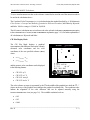
With the ever increasing premium placed on the quality of displayed images in medical diagnostics,
broadcasting, video production, animation, education, computer graphics, and advertising, a way to insure
accurate color presentation from the display units has become critical. The Model SLS 9400FC
Colorimeter has been specifically designed to meet the demand for a low cost, easy to use, high precision
instrument to control and allow easy adjustment of the color and brightness on any monitor.
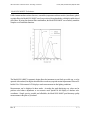
The Model SLS 9400FC has direct application in:
•
•
•
•
•
•
•
•
•
Video and post production
TV studios
Medical Imaging
Advertising
Computer Graphics
Desktop publishing
CRT manufacturing
Animation
Video wall presentations
and any other application where the need to control absolute color accuracy is a necessity.
The Model SLS 9400FC Colorimeter consists of a sensor head and a Handheld display unit. A built-in
rechargeable battery pack allows the instrument to be operated anywhere and the RS-232 serial
communication port makes remote data collection simple.
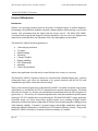
The key to the extremely high accuracy of the Model SLS 9400FC is it's ability to match the color response
of the human eye, as defined by the CIE 1931 standard observer spectral response functions. This match
allows the user to make very accurate color and luminance measurements across the full color gamut of a
typical color CRT . The accuracy of a colorimeter depends on how closely the instrument's spectral response
matches the CIE 1931 standard observer spectral response. The Model SLS 9400FC's unique, proprietary
sensor/filter design very closely mirrors these spectral response curves resulting in highly accurate
chromaticity measurements that are independent of field rate or the monitor's phosphor yielding precision
white balancing capability. Luminance is measured using a detector/filter combination, which closely
matches the response of the human eye as defined by the CIE Luminous Efficiency Function. This gives the
Model SLS 9400FC the ability to accurately measure the luminance of a monitor.
______________________________________________________________________________
Rev: E
1-1
UDT Instruments • 8581 Aero Drive • San Diego, CA 92123
Phone (858) 279-8035 Fax (858) 576-9286
Model SLS 9400FC Colorimeter
Unlike instruments that use three detectors, or unstable (temperature and time sensitive) interference, plastic
or gelatin filters, the Model SLS 9400FC uses four precision silicon photodiodes with highly stable colored
glass filters. By using four detector/filter combinations, the Model SLS 9400FC can accurately match the
complete set of tristimulus functions.
The Model SLS 9400FC's ergonomic design allows the instrument to rest firmly on a table top, or to be
operated with one hand, leaving the other hand free to make any required monitor adjustments. It has an EL
backlit 128 x 128 dot matrix LCD display to make measurements in dim lighting conditions.
Measurements can be displayed in three modes. An analog bar graph displaying RGB values used to
perform color balance adjustments or two numeric mode options for the display of absolute color
coordinates. Simple, precise, portable, and affordable, the Model SLS 9400FC puts laboratory quality
measurements in the palm of your hand.
______________________________________________________________________________
Rev: E
1-2
UDT Instruments • 8581 Aero Drive • San Diego, CA 92123
Phone (858) 279-8035 Fax (858) 576-9286
Model SLS 9400FC Colorimeter
Model SLS 9400FC Features
•
•
•
•
•
•
•
•
•
•
•
•
•
•
•
•
Remote computer control using an RS-232 interface (which can be disabled)
Large EL backlit 128 x 128 graphics LCD display with an anti-glare coating
A standard ¼-20 post mount insert on both the detector and display unit
Universal input power supply
A low profile suction cup (with a deactivation knob)
Numeric modes
• CIE 1931 xyY
• CIE 1976 u'v'Y
• CIE 1931 ∆x∆yY
• CIE 1976 ∆u'∆v'Y
• CIE 1931 XYZ
CIE plot modes
• CIE 1931 xyY
• CIE 1976 u'v'Y
• CIE 1931 ∆x∆yY
• CIE 1976 ∆u'∆v'Y
RGB bar graph mode
9 reference measurement storage locations
9 setup memory storage locations
9 phosphor memory storage locations
9 white reference memory storage locations
Display hold
Battery saver (which can be disabled)
Calibration reminder
Field calibration capability
Calibration
The calibration of the UDT Instruments Model SLS 9400FC is traceable to the National Institute of
Standards and Technology (NIST) and Physikalisch-Technische Bundesanstalt (PTB).
The Model SLS 9400FC has a built in calibration reminder. This feature informs the user that the
instrument needs to be recalibrated when the calibration cycle elapses. When the instrument needs to be
recalibrated, the calibration information will be displayed every time the instrument is turned on.
______________________________________________________________________________
Rev: E
1-3
UDT Instruments • 8581 Aero Drive • San Diego, CA 92123
Phone (858) 279-8035 Fax (858) 576-9286
Model SLS 9400FC Colorimeter
Caution
Use only the battery charger supplied with the instrument. Failure to do so may cause permanent
damage to the Model SLS 9400FC and may result in personal injury. To avoid electrical shock, use
proper care when using the battery charger.
Electrostatic Sensitive Device
All semiconductor devices are susceptible to electrostatic discharges (ESD). Ensure that the unit is
switched off before connecting or disconnecting the detector probe, battery charger, and RS-232 cable.
Failure to do so can cause ESD damage and reduce the lifetime of the instrument drastically.
______________________________________________________________________________
Rev: E
1-4
UDT Instruments • 8581 Aero Drive • San Diego, CA 92123
Phone (858) 279-8035 Fax (858) 576-9286
Model SLS 9400FC Colorimeter
Preparation for use
Model SLS 9400FC Inspection
The Model SLS 9400FC shipping carton contains the following items:
•
•
•
•
•
•
Model SLS 9400FC colorimeter
Hardside carrying case
Universal AC input battery charger with power cord
RS-232 adapter with cord
Instruction manual
Certificate of calibration
The instrument was inspected prior to shipment and was free of mechanical and electrical defects.
Immediately after unpacking the instrument, inspect for damage that may have occurred during transit. If
any damage is found, a claim should be filed with the carrier and UDT Instruments should be contacted for
a Return Materials Authorization (RMA) number.
Storage and Shipping
To prevent damage to the instrument, it is recommended that the package designed for the instrument be
used when shipping. The original packaging is intended to be used for shipping, carrying, and storage.
Instrument Identification
The model and serial number of the instrument are located on the "CALIBRATION RECORD" label attached to
the back of the Handheld indicator unit and the bottom of the detector head. The serial number of the
Handheld and head can also be determined by viewing the "CALIBRATION INFO" screen via the
CONFIGURATION 2 menu (the bottom right icon, see page 3-13).
Input Power Requirements
The Model SLS 9400FC receives its primary power from internal batteries. The approximate lifetime of
the batteries is fourteen hours without the backlight and seven hours with the backlight.
Before charging the batteries, turn the instrument OFF, plug the battery charger into the instrument, connect
the power cord to battery charger and then to the wall socket. With the instrument turned off, the batteries
will fully charge in approximately four hours. Because of this fast charging rate, the keypad and the
surrounding area will be warm. This is normal and there is no cause for alarm. The operation of the
instrument is not affected while the batteries are charging.
______________________________________________________________________________
Rev: E
2-1
UDT Instruments • 8581 Aero Drive • San Diego, CA 92123
Phone (858) 279-8035 Fax (858) 576-9286
Model SLS 9400FC Colorimeter
NOTE:
Due to the nature of NiCd batteries, the batteries may exhibit a reduced charge capacity over
time. This is typically caused by repetitive partial discharge/recharge cycles. To maintain
maximum battery charge capacity, operate the instrument until the battery is fully discharged
before recharging.
The battery charger is configured to supply the proper power to the Model SLS 9400FC independent of
the input voltage and frequency. The charger will function with an input voltage ranging from 100 to 240
volts AC at 47 to 63 Hz. The power supply has UL, CSA and TUV certifications .
Turn-on and Check Out Procedure
Connect the detector probe to the handheld unit, make sure not to over tighten the connector, and
press the PWR button. When the power button is depressed the instrument will beep and the icons will be
displayed at the bottom of the screen along with a message stating that the instrument is performing a selfcalibration. When the self calibration is completed the Model SLS 9400FC will start taking measurements
based on the configuration information in the DEFAULT setup memory location (see page 3-7 for more
information).
The Model SLS 9400FC is fully charged before it leaves the factory. However, if the instrument acts
erratically, fully charge the batteries before proceeding with the check out procedure.
Warm Up Period
The Model SLS 9400FC can be used immediately after it is turned ON . However, the Model SLS
9400FC will perform best if allowed to stabilize for at least 30 minutes before making precision
measurements. This is especially critical when making low luminance level color measurements.
Suction Cup
The Model SLS 9400FC is equipped with a suction cup, which makes it convenient to mount the probe
assembly to the CRT and thereby freeing the users hands. For maximum performance, the user needs to
verify that the lip of the suction cup and the CRT face are clean, and the knurled suction release valve is fully
seated. Failure to do so may result in premature release of the vacuum and may lead to damage of the
probe assembly.
To mount the probe assembly on the CRT simply press it against the CRT . To remove, hold detector
assembly while pulling back on one of the four nodules on the outside edge of the suction cup until suction is
released. Removing the suction cup by pulling directly on the lip or by pulling directly on the detector
assembly will cause damage to the suction cup.
______________________________________________________________________________
Rev: E
2-2
UDT Instruments • 8581 Aero Drive • San Diego, CA 92123
Phone (858) 279-8035 Fax (858) 576-9286
Model SLS 9400FC Colorimeter
In the event the suction mechanism is not needed, the suction cup can be used as a light shade by removing
the release valve and defeating the vacuum mechanism. A threaded hole has been provided in the bottom of
the probe assembly to store the release valve when not in use.
NOTE:
The suction cup has been designed to provide short term mounting capabilities. Should the user
require long term and/or fixed positioning, a ¼-20 post mount insert is provided for convenient
mounting.
______________________________________________________________________________
Rev: E
2-3
UDT Instruments • 8581 Aero Drive • San Diego, CA 92123
Phone (858) 279-8035 Fax (858) 576-9286
Model SLS 9400FC Colorimeter
Model SLS 9400FC Operation
Introduction
The Model SLS 9400FC operates in three modes: a numeric display mode, a CIE plot mode, and a RGB
bar graph mode.
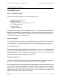
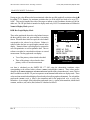
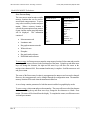
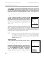
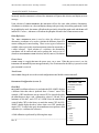
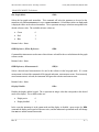
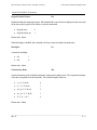
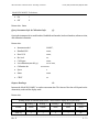
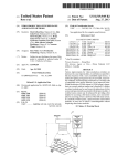
Numeric Display Mode
The numeric display mode displays the color
coordinates of a source, the luminance value in the
desired units of measure, the Correlated Color
Temperature and the color error ∆E (CIELUV). This
mode is used to perform absolute or differential color
measurements. The color coordinates can be
displayed in the following formats:
•
CIE 1931 xyY
•
CIE 1976 u'v' Y
•
CIE 1931 ∆x∆yY
•
CIE 1976 ∆u'∆v' Y
•
CIE 1931 XYZ
SLS 9400
COLORIMETER
.313
.329
x:
y:
Y:
T:
76.8 m
6500K
cd
2
E:
0.1
UDT Instruments
In the CIE 1931 ∆x∆y and CIE 1976 ∆u'∆v' modes, the reference is selected via the DELTA REFERENCE
menu option in the CONFIGURATION 2 menu (the bottom right icon, see page 3-13). Upon entry into this
mode, the displayed delta values are calculated as follows:
In CIE 1931 ∆x∆y:
•
∆x = x measured - x ref
•
∆y = y measured - y ref
In CIE 1976 ∆u'∆v':
•
∆u' = u' measured - u' ref
•
∆v' = v' measured - v' ref
______________________________________________________________________________
Rev: E
3-1
UDT Instruments • 8581 Aero Drive • San Diego, CA 92123
Phone (858) 279-8035 Fax (858) 576-9286
Model SLS 9400FC Colorimeter
To use a stored measurement value as the reference it must first be stored in one of the numeric modes to
be used in the calculations above.
The Correlated Color Temperature (CCT) is calculated using the method described by A. R. Robinson in
Color Science: Concepts and Methods, Quantitative Data and Formulae, 2nd Edition by Wyszecki
and Stiles. Valid CCT range is 2,500 K to 30,000 K.
The ∆E (CIELUV) calculation uses as its reference the value selected via the DELTA REFERENCE menu option
in the CONFIGURATION 1 menu (see DELTA REFERENCE explanation, page 3-16). For further explanation of
∆E calculations see Wyszecki and Stiles.
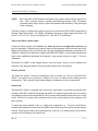
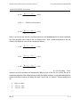
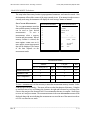
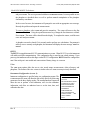
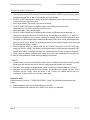
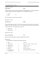
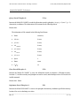
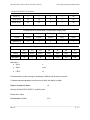
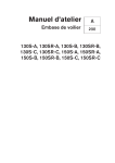
CIE Plot Display Mode
The CIE Plot Mode displays a graphical
representation of the difference between the currently
measured color coordinates and the color
coordinates of the user specified reference (REF:)
where:
SLS 9400
y
G
.
COLORIMETER
= 0.03
R
•
x = x measured - x ref
•
y = y measured - y ref
and the numeric color coordinates can be displayed
in the following formats:
•
CIE 1931 xyY
•
CIE 1976 u'v' Y
•
CIE 1931 ∆x∆yY
•
CIE 1976 ∆u'∆v' Y
B
x
x: .310
y: .310 T: 6423 K
Y: .75.2
cd / m2
REF: W#1 D65
UDT Instruments
The color reference or target is represented by the ¨ in the middle of the graphical area while the "¨ = "
(shown at the top of the graphical area) indicates the graphical resolution scale. The resolution scales
indicate the magnitude of the color difference and can be adjusted manually using the
ZOOM-CONFIGURATION icon (see page 3-6). The available resolution levels are:
•
0.05
•
0.03
•
0.004
______________________________________________________________________________
Rev: E
3-2
UDT Instruments • 8581 Aero Drive • San Diego, CA 92123
Phone (858) 279-8035 Fax (858) 576-9286
Model SLS 9400FC Colorimeter
During use, the color difference has been minimized within the specified graphically resolution when the n
lies within ¨. To illustrate, for maximum resolution the size of the target box needs to be set to "¨ =
0.004". This sets the length of the sides of the target to indicate a color coordinate deviation of 0.004 in
either axis. The CIE plot mode is intended as display mode only. RS-232 communications will follow the
Numeric Display Mode protocol.
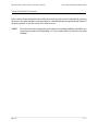
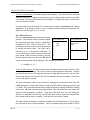
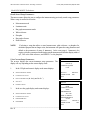
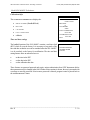
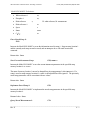
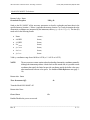
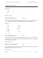
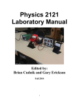
RGB Bar Graph Display Mode
The RGB bar graph mode shows the color balance between
the three primary colors, red, green and blue, in an analog
format. When the three values are equal, the color balance
corresponds to the selected RGB reference. Balance is
achieved when the bars are equal lengths centered in the
display. Numerical data is also displayed to present the
user with quantitative as well as qualitative data. The RGB
reference can either be a stored white reference or a stored
measurement. The bar graph mode can display:
•
•
Two of the primary colors related to the third
Three of the primary colors related to three
primary colors of a stored measurement
SLS 9400
COLORIMETER
R
G
B
-100
Y:
+100
76.8
cd
m2
WREF: #1 D65
PHOS: #1 SMPTE C
MODE: RB/G
UDT Instruments
data is calculated per the SMPTE RP 177-1993 using the chromaticity coordinate values
corresponding to the selected white reference (WREF:) and phosphor (PHOS :). These values maybe
changed via the WHITE REFERENCE and PHOSPHOR menu options in the CONFIGURATION 1 menu. The RGB
data is available over the RS-232 port in response to an R command while in the RGB display mode. These
values are then normalized and displayed based on the selected bar graph mode (MODE:). For selected bar
graph mode (MODE:) RG/B, B (blue) is the normalizer and for bar graph mode GB/R, R (red) is the
normalizer. As an example, if the selected bar graph mode is RB/G, G (green) is the normalizer, which is held
constant, and the R (red) and B (blue) balance is calculated as follows:
RGB
______________________________________________________________________________
Rev: E
3-3
UDT Instruments • 8581 Aero Drive • San Diego, CA 92123
Phone (858) 279-8035 Fax (858) 576-9286
Model SLS 9400FC Colorimeter
• ∆R =
( Rmeasured - R re f )
x 100%
( Gmeasured - G re f )
• ∆G = 0
• ∆B =
(TheSelect edNormaliz er)
( Bmeasured - B re f )
x 100%
( Gmeasured - G re f )
In the event, the user has selected a stored measurement as the RGB REFERENCE, the measurement must
have been previously stored while in the RGB display mode. With a stored measurement as the RGB
reference, the displayed values will be calculated as follows:
• ∆R =
( R m e a s u r e d - R re f )
x 100%
Rre f
• ∆G =
( G m e a s u r e d - G re f )
x 100%
G ref
• ∆B =
( B m e a s u r e d - B re f )
x 100%
Bre f
The Model SLS 9400FC provides manual (see page 3-15) and automatic RGB bar scaling. In the
automatic mode the instrument will automatically adjust the scale of the RGB bars to allow the user to
conveniently adjust the colors without having to modify the display resolution. A scale independent numeric
readout to the right of each bar will display the actual value of ∆R, ∆G, and ∆B. The three scaling levels
are:
•
-100% to 100%
•
- 25% to 25%
•
- 10% to 10%
______________________________________________________________________________
Rev: E
3-4
UDT Instruments • 8581 Aero Drive • San Diego, CA 92123
Phone (858) 279-8035 Fax (858) 576-9286
Model SLS 9400FC Colorimeter
When the value of ∆R, ∆G, and ∆B equals zero, the color balance corresponds to the selected reference.
This is indicated when the bars are centered while the RGB scaling is set to the highest resolution (±10%).
The RGB measurements are independent of the luminance level.
NOTE:
The RGB calculations are directly dependent on the white reference and the phosphor of the
monitor. To ensure accurate rgb measurements it is very important that the correct phosphor
type is selected. If the monitor under test does not use either the smpte c or the ebu phosphor,
then it is necessary to characterize the phosphor used in the monitor. This can be done by the
Model SLS 9400FC's phosphor learn mode or entered manually if the chromaticity coordinate
values are known for the primary colors. For further information see the SMPTE
Recommended Practice, "Derivation of Basic Television Color Equations", RP 177, for details
concerning the proper derivation of rgb data.
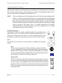
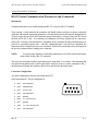
Instrument Operation
The Model SLS 9400FC is primarily controlled through five icons displayed at the
bottom of the screen. To move between the icons use the left and right arrow keys. To
activate the icon function press the enter key. To move around in the menus use the
left, right, up, and down keys, and press the enter key to activate a menu selection.
Icons:
The function of each icon and its associated menus are explained in the following
section.
Stop:
The stop icon is a toggle switch. When the ENTER key is depressed while the
stop icon is highlighted, the instrument will stop performing measurements and enters
the hold mode. The stop icon will be replaced with a flashing H icon. When the
enter key is depressed again the instrument will resume measuring and the stop icon
will be displayed. All menus are available in either mode.
Display Mode:
The DISPLAY MODE icon will select between the three display modes. Use the updown arrow keys to scroll through the available display modes and the ENTER key to
select a new mode. The configuration of each mode will depend on the current setup
parameters. When the instrument is in the HOLD mode and a new display mode is
selected, the instrument will deactivate the HOLD mode and changes to the new
measurement mode.
______________________________________________________________________________
Rev: E
3-5
UDT Instruments • 8581 Aero Drive • San Diego, CA 92123
Phone (858) 279-8035 Fax (858) 576-9286
Model SLS 9400FC Colorimeter
Save
The save icon will display the save menu. This menu allows the user to save the
current setup parameters, the current measurement, white reference, or phosphor
chromaticity coordinates, and the state of RS-232 communications.
View
The view icon will display the view menu. This menu allows the user to view the
stored setup, measurement, white reference and phosphor chromaticity coordinates.
Configuration
The configuration icon is used to configure the Model SLS 9400FC setup
parameters and to view the current status and calibration information. The zoomconfiguration icon indicates manual scaling is active (rgb and cie plot modes). Use
the up and down arrow keys to change the scaling resolution. Press the enter key to
enter the configuration menu.
Menu Options
Use the up and down arrow keys to scroll through the menus and the enter key to select a function. To
allow for faster movement within the save, recall, view, and configuration menus and sub-menus, the left
arrow key positions the cursor at the first menu selection and the right arrow key moves the cursor to the
exit menu selection.
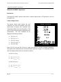
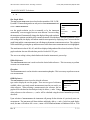
Save Menu
The save menu is used to store and erase setup parameters, measurement
values, white reference values, phosphor values, and change the state of RS232 communications.
SAVE
SETUP
MEASUREMENT
WHITE REFERENCE
PHOSPHOR
RS232
ON
EXIT
______________________________________________________________________________
Rev: E
3-6
UDT Instruments • 8581 Aero Drive • San Diego, CA 92123
Phone (858) 279-8035 Fax (858) 576-9286
Model SLS 9400FC Colorimeter
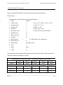
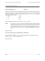
Save Current Setup
The SAVE SETUP menu has nine available
memory locations that can be used to
store desired setup parameters. To save a
setup, select a memory location and press
ENTER.
When a memory location is
selected, the menu options NAME, SAVE AS
#, EXIT, and the current setup information
will be displayed. This information
consists of:
• Measurement mode
• Luminance units
SAVE SETUP
1.
2.
3.
4.
5.
6.
7.
8.
9.
EXIT
SAVE SETUP
NAME: DEFAULT
SAVE AS # 1
EXIT
CIE 1931 xy
cd/m2
RB/G
D65
SMPTE C
RGBREF: W#1
DREF: W#1
• Bar graph measurement mode
• White reference
• Phosphor
• Bar graph mode reference
• Differential mode reference
To save a setup, it is first necessary to name the setup memory location. Select NAME and press the
ENTER key. The cursor will move to the first character of the name. Using the up and down arrow
keys will change the character, the right and left arrow keys will move the cursor to the
next/previous character field. Press ENTER when the entry is complete. Scroll down to SAVE AS #
and press ENTER.
The name of the first memory location is preprogrammed to DEFAULT and can not be changed.
However, the setup parameters can be changed through the configuration menu. The DEFAULT
memory location will be used when the instrument is turned on.
A saved setup contains parameters for both the numeric and the bar graph display modes.
To erase a setup, select NAME and press the ENTER key. The cursor will move to the first character
of the name. Using the up and down arrow keys, change the first character to a blank. Press
ENTER. The name will be cleared from the display. To complete the erasure, scroll down to SAVE
AS # and press ENTER.
______________________________________________________________________________
Rev: E
3-7
UDT Instruments • 8581 Aero Drive • San Diego, CA 92123
Phone (858) 279-8035 Fax (858) 576-9286
Model SLS 9400FC Colorimeter
The setup in the first memory location is preprogrammed to DEFAULT and can not be erased. Also
the instrument will not allow erasure of the setup currently in use. If an attempt is made to erase a
currently used setup, the instrument will display the error message "MEM LOC ERROR".
Save Current Measurement:
The save MEASUREMENT menu has
nine available memory locations that
can be used to store desired
measurements.
To save a
measurement, select a memory
location and press ENTER. When a
memory location is selected, the
menu options NAME, SAVE AS #,
EXIT, and the current measurement
data will be displayed. The format
of the data depends on the
measurement mode.
SAVE MEASUREMENT
1.
2.
3.
4.
5.
6.
7.
8.
9.
EXIT
SAVE MEASUREMENT
NAME:
SAVE AS #1
EXIT
x
y
-------------------------------0.376
0.389
Y:
T:
DE:
39.9 cd/m2
4185 K
57.8
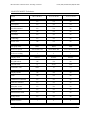
Measurement Modes
Numeric
CIE plot
Bar
xy, u'v', ∆x∆y,∆u'∆v'
XYZ
xy, u'v', ∆x∆y,∆u'∆v'
RGB
Measurement Data
ü
ü
ü
ü
Luminance Value
ü
ü
ü
Color Temperature
ü
∆E (CIELUV)
ü
ü
ü
To save a measurement, it is first necessary to name the measurement memory location. Select
NAME and press the ENTER key. The cursor will move to the first character of the name. Using the
up and down arrow keys will change the character, the right and left arrow keys will move the
cursor to the next/previous character field. Press ENTER when the entry is complete. Scroll down
to SAVE AS # and press ENTER. The measurement name in the SAVE MEASUREMENT menu will be
displayed along with NUM indicating the measurement was stored in one of the numeric modes or
RGB if it was stored in RGB mode.
______________________________________________________________________________
Rev: E
3-8
UDT Instruments • 8581 Aero Drive • San Diego, CA 92123
Phone (858) 279-8035 Fax (858) 576-9286
Model SLS 9400FC Colorimeter
To erase a measurement, select NAME and press the ENTER key. The cursor will move to the first
character of the name. Using the up and down arrow keys, change the first character to a blank.
Press ENTER. The name will be cleared from the display. To complete the erasure, scroll down to
SAVE AS # and press ENTER.
A measurement can not be cleared if it is currently used as either a RGB REFERENCE or a DELTA
REFERENCE. If an attempt is made to erase a currently used measurement, the instrument will
display the error message "MEM LOC ERROR".
Save White Reference:
The save WHITE REFERENCE menu has nine memory
SAVE WHITE REF
locations. The first three memory locations contain
the preprogrammed white reference chromaticity 1. D65
2. 3200K
coordinates for D65, 3200 K and 9300 K. The
3. 9300K
remaining six memory locations can be programmed 4.
5.
by entering the desired values. The values can be
6.
entered as xy or u'v' chromaticity coordinates. To
7.
save a white reference, select a memory location and 8.
press ENTER. When a memory location is selected,
9.
the menu options NAME, SAVE AS #, EXIT, è, and the
current measurement data will be displayed. This information consists of:
SAVE WHITE REF
NAME: D65
SAVE AS #4
EXIT
è
x
y
0.3127 0.3291
• Reading (xy, u'v')
To save a white reference, it is first necessary to name the white reference memory location. Select
NAME and press the ENTER key. The cursor will move to the first character of the name. Using the
up and down arrow keys will change the character, the right and left arrow keys will move the
cursor to the next/previous character field. Press ENTER when the entry is complete. Scroll down
to SAVE AS # and press ENTER.
The entry chromaticity mode can be selected by changing the measurement mode from the
configuration menu. Saving a white reference is only accessible while the instrument is in the xy and
u'v' modes. The current measurement data is displayed and can be manually modified by scrolling
to the arrow, è, menu selection and pressing ENTER. This will position the cursor on the first
character of the chromaticity coordinate. Using the up and down arrow keys will change the
character, the right and left arrow keys will move the cursor to the next/previous character field.
Press ENTER when the entry is complete. Scroll to SAVE AS # and press ENTER.
The white reference chromaticity coordinates are displayed to four decimal places. This is done to
prevent round off errors in the calculations. Valid xy coordinates range from 0.0048 to 0.8338
______________________________________________________________________________
Rev: E
3-9
UDT Instruments • 8581 Aero Drive • San Diego, CA 92123
Phone (858) 279-8035 Fax (858) 576-9286
Model SLS 9400FC Colorimeter
(u'v': 0.0159 to 0.6233). The limits have been selected based on tabular data of Table I (3.3.1)
Color-Matching Functions an Corresponding Chromaticity Coordinates of the CIE 1931 Standard
Colorimetric System, for λ= 360 to 830 nm at 1 - nm Intervals in Color Science: Concepts and
Methods, Quantitative Data and Formulae, second edition, by Wyszecki and Stiles (1982).
NOTE: The user must use extreme caution when entering chromaticity coordinates manually.
Although the instrument performs a limits check on the entered data, it is possible to
enter coordinates that satisfy the limits but provide coordinates outside the define
color space when transformed between color spaces. For example, entering x & y =
0.0159 (the u'v' lower limit) will pass the xy limits check, and the instrument will
accept and use these values. However, when transformed and viewed in the u'v'
mode these values are not defined within the u' v' color space.
x = 0.0159
y = 0.0159
è
è
u' = 0.0061
v' = 0.0453
To erase a white reference, select NAME and press the ENTER key. The cursor will move to the first
character of the name. Using the up and down arrow keys, change the first character to a blank.
Press ENTER. The name will be cleared from the display. To complete the erasure, scroll down to
SAVE AS # and press ENTER.
A white reference can not be cleared if it is currently used to perform RGB calculations, as a RGB
REFERENCE or a DELTA REFERENCE. If an attempt is made to erase a currently used white
reference, the instrument will display the error message "MEM LOC ERROR".
Save Phosphor:
The save PHOSPHOR menu has nine memory locations. The first two memory
locations contain the preprogrammed phosphor chromaticity coordinates for
SMPTE C and EBU standard phosphors. The remaining eight memory locations
can be programmed by entering the desired chromaticity coordinates. The
values can be entered as xy or u'v' chromaticity coordinates. To save a
phosphor, select a memory location and press ENTER. When a memory
location is selected, the menu options NAME, SAVE AS #, EXIT, LEARN, R, G, B,
and the current measurement data will be displayed for each phosphor
primary color.
SAVE PHOSPHOR
1. SMPTE C
2. EBU
3.
4.
5.
6.
7.
8.
9.
• Reading R (xy, u'v')
• Reading G (xy, u'v')
• Reading B (xy, u'v')
______________________________________________________________________________
Rev: E
3 - 10
UDT Instruments • 8581 Aero Drive • San Diego, CA 92123
Phone (858) 279-8035 Fax (858) 576-9286
Model SLS 9400FC Colorimeter
To save a phosphor, it is first necessary to name the phosphor memory location. Select NAME and
press the ENTER key. The cursor will move to the first character of the name. Using the up and
down arrow keys will change the character, the right and left arrow keys will move the cursor to the
next/previous character field. Press ENTER when the entry is complete. Scroll down to SAVE AS #
and press ENTER. There are two ways to save a phosphor: manual entry mode and learn mode.
Phosphor Manual Entry Mode:
To modify the chromaticity coordinates of a phosphor, scroll to the
appropriate menu selection and press ENTER. This will position the
cursor on the first character of the chromaticity coordinate. Using the up
and down arrow keys will change the character, the right and left arrow
keys will move the cursor to the next character field. Press ENTER when
the entry is complete. When all entries are complete scroll to SAVE AS #
and press ENTER.
SAVE PHOSPHOR
NAME:
SAVE AS #3
EXIT
LEARN
R:
G:
B:
x
y
0.3333 0.3333
0.3333 0.3333
0.3333 0.3333
The phosphor chromaticity coordinates are displayed to four decimal
places. This is done to prevent round off errors in the calculations.
Valid xy coordinates range from 0.0048 to 0.8338 (u'v': 0.0159 to 0.6233). The entry mode can
be selected by changing the measurement mode from the configuration menu. Saving a phosphor is
only accessible while the instrument is in the xy and u'v' modes.
NOTE:
The user must use extreme caution when entering chromaticity coordinates manually.
Although the instrument performs a limits check on the entered data, it is possible to
enter coordinates that satisfy the limits but provide coordinates outside the defined
color space when transformed between color spaces. See the Save White
Reference note (page 3-10).
Phosphor Learn Mode:
To enter the learn mode scroll to LEARN and press ENTER. The user is
presented with three menu selections: MEASURE RED, MEASURE GREEN,
and MEASURE BLUE. To correctly determine the chromaticity
coordinates of each primary color it is necessary to turn on one gun at a
time and take a corresponding measurement. When the desired gun is
on, scroll to the corresponding measurement selection (ie. if the red gun
is on select MEASURE RED) and press ENTER. The instrument will
respond with PROCESSING... to indicate that a measurement is
underway. When the measurement is complete the chromaticity
coordinates will be displayed. Repeat for remaining guns. Scroll to EXIT
SAVE PHOSPHOR
NAME:
SAVE AS #3
EXIT
x
y
R:
G:
B:
MEASURE RED
MEASURE GREEN
MEASURE BLUE
______________________________________________________________________________
Rev: E
3 - 11
UDT Instruments • 8581 Aero Drive • San Diego, CA 92123
Phone (858) 279-8035 Fax (858) 576-9286
Model SLS 9400FC Colorimeter
and press ENTER. The user is presented with the SAVE PHOSPHOR menu. It is now possible to save
the phosphor as described above as well as perform manual manipulation of the phosphor
chromaticity coordinates.
In the event of an error, the instrument will prompt the user with an appropriate error message.
Remedy the problem and repeat the measurements.
To erase a phosphor, select NAME and press the ENTER key. The cursor will move to the first
character of the name. Using the up and down arrow keys, change the first character to a blank.
Press ENTER. The name will be cleared from the display. To complete the erasure, scroll down to
SAVE AS # and press ENTER.
A phosphor can not be cleared if it is currently used to perform RGB calculations. If an attempt is
made to erase a currently used phosphor, the instrument will display the error message "MEM LOC
ERROR".
RS232:
The RS232 is a toggle that turns RS-232 communications ON or OFF. When RS-232 is ON , the instrument
will enable serial port communications. This configuration flag is stored in non-volatile memory. Upon
power up, the instrument will use this flag to set the RS-232 configuration. RS232 should be configured to
OFF if the serial port is not needed and conservation of battery charge is a concern.
View:
The VIEW menu options allow the user to view stored setups, measurements, white references, and
phosphors. The format of the view screens is similar to the save menu screens previously described.
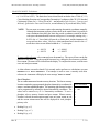
Instrument Configuration (screen 1):
Instrument configuration is specified using two configuration menus. The
CONFIGURATION 1 menu will allow the user to fully specify all of the setup
parameters for the three display modes. The CONFIGURATION 2 menu will
allow the user to perform a field calibration, well view the calibration
information, and allow an authorized user to set the time, date, and
calibration due date.
CONFIGURATION 1
RECALL SETUP
STATUS
MEASUREMENT MODE
LUMINANCE UNITS
BAR GRAPH MODE
WHITE REFERENCE
PHOSPHOR
RGB REFERENCE
DELTA REFERENCE
POWER SAVER:
ON
NEXT SCREEN
EXIT
______________________________________________________________________________
Rev: E
3 - 12
UDT Instruments • 8581 Aero Drive • San Diego, CA 92123
Phone (858) 279-8035 Fax (858) 576-9286
Model SLS 9400FC Colorimeter
Recall Stored Setup Parameters:
The RECALL SETUP allows the user to configure the instrument using previously stored setup parameters.
When a setup is recalled it will set the:
• Measurement mode
• Luminance units
• Bar graph measurement mode
• White reference
• Phosphor
• Bar graph reference
• Delta reference
NOTE:
If selecting a setup that utilizes a stored measurement, white reference, or phosphor for
calculation purposes that no longer exists, the instrument will ignore the setup parameters and
default to the parameters of setup #1 (DEFAULT). In the event setup # 1 (DEFAULT) also
requires reference parameters that no longer exist the instrument will default to display mode of
xyY, D65 as the white reference, and SMPTE C as the phosphor.
View Current Setup Parameters:
The STATUS displays the current instrument setup parameters. The
display will vary depending on the current display mode.
1.
In the CIE plot and numeric display mode status displays:
•
MEASUREMENT MODE
•
LUMINANCE UNITS
•
DELTA REFERENCE (in ∆x∆y and ∆u'∆v'
•
SETUP
•
POWER SAVER
2.
SETUP #1
POWER SAVER
EXIT
In the RGB bar graph display mode status displays:
MEASUREMENT MODE
•
LUMINANCE UNITS
•
RGB REFERENCE
•
PHOSPHOR
DEFAULT
OFF
)
#.
•
STATUS
MEASUREMENT MODE
CIE 1931 xy
LUMINANCE UNITS
Cd/m2
STATUS
MEASUREMENT MODE
RG/B
LUMINANCE UNITS
cd/m2
RGB REFERENCE
W#1 D65
PHOS: #1 SMPTE C
WHITE REFERENCE
#1 D65
SETUP #1
DEFAULT
POWER SAVER
OFF
EXIT
______________________________________________________________________________
Rev: E
3 - 13
UDT Instruments • 8581 Aero Drive • San Diego, CA 92123
Phone (858) 279-8035 Fax (858) 576-9286
Model SLS 9400FC Colorimeter
•
WHITE REFERENCE
•
SETUP
•
POWER SAVER
#
The SETUP #, which is located at the bottom of the screen, displays the name of the memory location of the
currently loaded setup. If any of the setup parameters previously set have been changed or erased, the
SETUP # will display MODIFIED .
Set Measurement Mode:
The MEASUREMENT MODE menu is used to select the desired
measurement mode. The available measurement modes are:
• CIE 1931 xyY chromaticity coordinates
• CIE 1976 u'v' Y uniform color space coordinates
• CIE 1931 ∆x∆yY, the delta measurement is performed with
MEASUREMENT MODE
CIE 1931 xy
CIE 1976 u’v’
CIE 1931 dxdy
CIE 1976 du’dv’
CIE 1931 XYZ
EXIT
respect to either a stored measurement or a stored white
reference
• CIE 1976 ∆u'∆v' Y, the delta measurement is performed with respect to either a stored
measurement or a stored white reference
• CIE 1931 XYZ tri-stimulus values
NOTE:
Ideally, the "Y" value in all numeric display modes should be identical. However, the
Model SLS 9400FC handles (displays) the CIE 1931 XYZ mode's "Y" value differently than
the "Y" values displayed in the remaining display modes. Specifically, the "Y" values displayed
in all modes other than the CIE 1931 XYZ mode are of the units fL, cd/m2 , and NITS which
are based on a luminance calibration. In the CIE 1931 XYZ mode, the "Y" value is based on
an illuminance calibration (units of lux). This deviation allows UDT Instruments to maintain
direct correlation to the in-house calibration standards. In the event CIE 1931 XYZ values
based on luminance are desired, the user need only to mathematically compensate by scaling
the displayed XYZ values to the "Y" value of the remaining modes.
Luminance Units:
The LUMINANCE UNITS menu is used to select the photometric units:
• cd/m2
• fL
LUMINANCE UNITS
cd/m2
fL
nt
EXIT
______________________________________________________________________________
Rev: E
3 - 14
UDT Instruments • 8581 Aero Drive • San Diego, CA 92123
Phone (858) 279-8035 Fax (858) 576-9286
Model SLS 9400FC Colorimeter
• nt
Bar Graph Mode:
The BAR GRAPH MODE menu is used to select the normalizer. RB / G, GB /
R, and RG / B normalizing modes are only active when a RGB REFERENCE is
set to a WHITE REFERENCE.
BAR GRAPH MODE
RB/G
GB/R
RG/B
SCALING
AUTO
EXIT
bar graph resolution can be set manually or by the instrument
automatically. SCALING toggles between AUTO and MAN. In AUTO scaling,
the instrument will automatically change the displayed bar graph resolution
to provide the optimum resolution of the currently measured color imbalance. When the instrument is in the
MAN scaling mode, the display will indicate manual zoom operation by displaying "MAN " between the bar
graph limits and the CONFIGURATION icon will change to the ZOOM CONFIGURATION icon. The resolution
can be modified by pressing the up and down arrows while the ZOOM CONFIGURATION icon is highlighted.
RGB
The actual numeric value of ∆R, ∆G, and ∆B are displayed independent of the selected resolution. The bar
graph resolution does not affect the data provided via the RS-232 port.
The AUTO RGB scaling is always the default mode when the instrument is powered up.
White Reference:
The WHITE REFERENCE menu is used to select the desired white reference. This is necessary to perform
accurate RGB measurements.
Phosphor:
The PHOSPHOR menu is used to select the current monitor phosphor. This is necessary to perform accurate
RGB measurements.
RGB Reference:
The RGB REFERENCE menu is used to select the reference
RGB REFERENCE
type used to display the RGB bar graphs. There are two types of references MEASUREMENT
available; either a previously stored measurement (stored in RGB mode) or a WHITE REF
EXIT
white reference. When selecting a measurement as the reference, the bar
graphs will be calculated as described previously for delta R, G, and B. Using a
white reference as the reference R, G, and B will be calculated using the selected normalizer previously
described.
Upon selection of MEASUREMENT the instrument will prompt for the selection of a previously store RGB
measurement. The instrument will then calculate and display delta R, G, and B. In the bar graph display
mode, the REF: will indicate M# <name>, PHOS : will be blank and MODE: will indicate RGB/RGB. If an
______________________________________________________________________________
Rev: E
3 - 15
UDT Instruments • 8581 Aero Drive • San Diego, CA 92123
Phone (858) 279-8035 Fax (858) 576-9286
Model SLS 9400FC Colorimeter
incorrectly stored measurement is selected, the instrument will ignore this selection, and display an error
message.
Upon selection of WHITE REFERENCE the instrument will use the same white reference chromaticity
coordinates to calculate RGB values and displays them per the previously selected bar graph mode. In the
bar graph display mode, the MODE: will indicate the previously selected bar graph mode and the REF: will
indicate W# <name>, and PHOS : will indicate the phosphor selected in the CONFIGURATION menu.
Delta Reference:
The DELTA REFERENCE menu is used to select the reference type
chromaticy coordinates to be used to calculate the difference between a
current reading and a stored reading. There are two types of references
available; either a previously stored measurement (stored in NUM mode) or
a white reference. Upon selection of a reference, the chromaticity
coordinates will be retrieved and used to perform the ∆x∆y or ∆u'∆v'
(based on MEASUREMENT MODE selection), and ∆E (CIELUV) calculations.
DELTA REFERENCE
MEASUREMENT
WHITE REF
EXIT
Power Saver:
is a toggle that turns the power saver ON or OFF. When the power saver is ON , the
instrument will automatically turn OFF approximately 10 to 20 minutes after the last key is pressed or serial
port command is received.
POWER SAVER
Next Screen:
NEXT SCREEN
brings the user to the second configuration menu labeled CONFIGURATION 2.
Instrument Configuration (screen 2):
Recal Ref.
RECAL REF. (recalibrate reference) is used when the SLS-9400FC displays
a different value than what is predicted from a “known” source. For
example, a CRT manufacturer sets up a master CRT to what is believed by
the manufacturer to have x and y chromaticity values of .300 and .300, a
luminance of 100 cd/m2, and a CCT of 15,000K. Since the manufacturer
wants all other CRTs in the factory to match the master CRT, the SLS9400FC should display the above values when a new CRT matches the
master CRT. To achieve this goal, the manufacturer must perform a field
calibration (i.e. recalibrate the reference).
CONFIGURATION 2
RECAL REF.
EMULATION OFF
CALIBRATION INFO
SET DATE
SET TIME
EXIT
RECAL REF.
SET x
SET y
SET Y
SET T
COMPUTE
EXIT
x 0.300
y 0.300
Y 100.0
______________________________________________________________________________
T 15000
Rev: E
3 - 16
A field calibration is performed by following these steps:
UDT Instruments • 8581 Aero Drive • San Diego, CA 92123
Phone (858) 279-8035 Fax (858) 576-9286
Model SLS 9400FC Colorimeter
1. From the main screen (which is the first screen seen when the SLS-9400FC is powered up), go to the
configuration menu. This is done by selecting the icon at the far right.
2. The SLS-9400FC should now be displaying the first configuration screen where CONFIGURATION 1
is written across the top of the screen.
3. Select NEXT SCREEN . This option is the next to last option.
4. The SLS-9400FC should now be displaying the second configuration screen where
CONFIGURATION 2 is written across the top of the screen.
5. Select RECAL REF.. This is the first option.
6. The SLS-9400FC should now be displaying the reference recalibration screen RECAL REF. is
written across the top of the screen. From this screen, it is possible to recalibrate x, y, Y, and/or T.
7. Choosing one variable at a time, select the variable to be changed. When a variable is selected, a cursor
will appear over the first digit of that variable near the bottom of the screen. Use the left and right arrow
keys to move the cursor, and use the up and down arrow keys to change the digits. Press the ENTER
key when finished editing a variable.
8. When all known values are entered, hold the SLS-9400FC head piece to the CRT and select
COMPUTE. The SLS-9400FC will display a calculation message. Keep the head piece against the CRT
until the SLS-9400FC is finished calculating. The CONFIGURATION 2 screen will then be displayed.
9. Finally, make sure that the emulation mode, which can be seen in the CONFIGURATION 2 menu, is ON .
10. EXIT the CONFIGURATION 2 menu and begin taking measurements.
NOTES:
The RECAL REF. screen has a key debounce feature. Once a variable has been selected to edit, pressing
ENTER again will not allow the user to leave the editing mode until another key is pressed.
• The values of the variables in the RECAL REF. screen do not get saved until COMPUTE is selected.
• Sometimes it is desirable to calculate some variables, but not others. For example, one may wish to
recalibrate only the x and y values but not the Y and T values. For variables that are not to be
recalibrated, set those values to 0 in the RECAL REF. menu.
•
Emulation mode
Emulation mode is set in the “CONFIGURATION 2” screen. The following best summarizes this
feature:
• When emulation mode is ON , the field calibration is in effect.
• When emulation mode is OFF, the SLS-9400FC uses factory set calibration.
______________________________________________________________________________
Rev: E
3 - 17
UDT Instruments • 8581 Aero Drive • San Diego, CA 92123
Phone (858) 279-8035 Fax (858) 576-9286
Model SLS 9400FC Colorimeter
Calibration Info:
The CALIBRATION INFORMATION displays the:
•
SERIAL NUMBER
•
REV LEVEL
•
CAL REPORT
•
LAST CALIBRATION
(Handheld/Head)
• calibratio
CALIBRATION INFO
SERIAL NUMBER
8A029 / 8A029
REV LEVEL
D_
CAL REPORT
90020
LAST CALIBRATION
04-16-1999
CALIBRATION DUE
10-16-1999
EXIT
Time and date settings
The handheld portion of the SLS-9400FC contains a real time clock
(RTC) which is set at the factory. It is necessary to keep track of the
time and date so that the user can be reminded when the SLS-9400FC
is to be sent back to the factory for recalibration. The time and date
setting features allow an authorized user to:
•
•
•
ENTER PASSWORD
OR PRESS ENTER
TO EXIT
set the time in the RTC
set the date in the RTC
set the calibration due date
These features are password protected and require written authorization from UDT Instruments before
these parameters may be changed in the field. If either of these options is chosen, the user is presented with
a message to enter the password. If an incorrect password is entered, program control is passed back to
the CONFIGURATION 2 menu.
______________________________________________________________________________
Rev: E
3 - 18
UDT Instruments • 8581 Aero Drive • San Diego, CA 92123
Phone (858) 279-8035 Fax (858) 576-9286
Model SLS 9400FC Colorimeter
RS-232 Serial Communication Parameters and Commands
Introduction
All instrument features are accessible through the RS-232 serial port (RS-232 enabled).
Upon entering a valid command, the instrument will disable further serial port reception, perform the
command, and return the appropriate information. All commands sent from the computer, through the RS232 port, need to be upper case ASCII character strings terminated by a carriage return (ASCII 13) and a
linefeed (ASCII 10); ie. R__ . As a minimum, the instrument will always respond with five status bytes
followed by a carriage return and linefeed. Depending on the command, the status information may be
prefixed by command response data. After this command/response cycle has been completed, the
instrument will be available to process a new command. Therefore the user should wait for the response to
the previous command before sending a new command.
NOTE:
To ensure proper operation, verify that the instrument is in one of the measurement display
modes before issuing a RS-232 command.
The serial port commands and the keypad functions are interrelated. For example, if the instrument has
been placed in the HOLD mode via the keypad and the serial port receives a UNITS command (ie. U0__ ),
the instrument will change the luminance units to cd/m2 and remain in the HOLD mode.
Connector Configuration
An 9 pin D-Subminiature connector is provided for RS-232
serial communication. The pin configuration is:
• pin 1
not connected
• pin 2
transmit (out)
• pin 3
receive (in)
• pin 4
not connected
• pin 5
ground
• pin 6
VCC
• pin 7
ground
• pin 8
VCC
• pin 9
not connected
(do not use!)
aux. (do not use!)
______________________________________________________________________________
Rev: E
4-1
UDT Instruments • 8581 Aero Drive • San Diego, CA 92123
Phone (858) 279-8035 Fax (858) 576-9286
Model SLS 9400FC Colorimeter
Communication Protocol
The serial port is a duplexed, asynchronous RS-232 port utilizing Tx and Rx only. To ensure proper
communication with the Model SLS 9400FC via the RS-232 serial port, the computer's communication
parameters must be configured to match the communication parameters of the Model SLS 9400FC.
The default communication parameters are:
•
•
•
•
Baud Rate
Parity
Data Bits
Stop Bits
9600
None
8
1
Command Nomenclature
#
Storage location for retained setups, measurements, white references and phosphors. Legal
values range from 1 to 9 unless otherwise noted. An attempt to access a specified
memory location which does not contain proper data will result in an invalid command.
<name>
Name assigned to the retained storage location. The name must consist of at least one valid
character and can not exceed eight. The valid characters are A →Z, 0 →9, space ( ^ ) and
underscore ( _ ).
Commands
A summary of the RS-232 commands are in Appendix A.
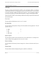
Readings Averaged:
ANx:
Sets the number of A/D readings to be averaged per channel to create a color measurement. The number
of averages are calculated as 2x where valid values of x range from 0 to 4. On powerup, the number of
averages is set to 1 (20 ). The instrument accumulates x number of readings before proceeding to the next
channel. After all four channels have been measured, the instrument then calculates the appropriate color
coordinates. For values of x greater than one, the instrument's response times will increase from those
listed in Appendix A.
Returned value: Status
______________________________________________________________________________
Rev: E
4-2
UDT Instruments • 8581 Aero Drive • San Diego, CA 92123
Phone (858) 279-8035 Fax (858) 576-9286
Model SLS 9400FC Colorimeter
Bar Graph Mode:
BMx:
Selects the bar graph mode normalizer. This command will select the parameter to be used as the
normalizer only when RGB REFERENCE is set to a WHITE REFERENCE. Color balance in the RGB display mode
is displayed relative to the selected normalizer. The x represents an integer value that corresponds to the
desired reference value. The available reference values are:
• Green
0
• Red
1
• Blue
2
Returned value: Status
RGB Reference; White Reference:
BR0:
Commands the instrument to use the same white reference selected for the RGB calculation as the bar graph
reference mode.
Returned value: Status
RGB Reference; Measurement #:
BR1,#:
Selects a desired stored measurement to be used as the reference in the bar graph mode. If a vacant
measurement is selected the command will be ignored and return measurement vacant. If an incorrectly
stored measurement is selected, the instrument will ignore this selection and return an error.
Returned value: Status
Display Disable:
DDx:
Disables the display and the keypad. The x represents an integer value that corresponds to the desired
mode of the display. The available modes are:
• Display active
0
• Display disabled
1
In the event the instrument is in the HOLD mode and the display is disabled, upon receipt of a DD0
command the display and keypad will become active, and the instrument's operational mode will change
from HOLD to normal measurement mode.
______________________________________________________________________________
Rev: E
4-3
UDT Instruments • 8581 Aero Drive • San Diego, CA 92123
Phone (858) 279-8035 Fax (858) 576-9286
Model SLS 9400FC Colorimeter
Returned value: Status
Display Mode:
DMx:
Changes the display mode between numeric display mode and bar graph mode. The x represents an integer
value that corresponds to the desired display mode. The available display modes are:
• Numeric
0
• Bar
1
The CIE plot mode can not be selected via RS-232.
Returned value: Status
Delta Reference:
DRy,#:
Selects the desired memory location, of either a stored measurement or white reference to be used as the
reference in the delta mode (∆x∆y, ∆u'∆v'). The y represents an integer value that corresponds to the
desired reference type. The available reference types are:
• Measurement
0
• White reference
1
Returned value: Status
Query Stored Setup #:
E?#:
Instructs the Model SLS 9400FC to send the information stored in setup #.
Returned value:
The information will be returned in the following fixed format:
• Name
xxxxxxxx,
• Chroma mode
x,
0: xy, 1: u'v', 2: ∆x∆y, 3: ∆u'∆v', 4: XYZ
• Luminance units
x,
0: cd/m2, 1: f L, 2: nt
• Display mode
x,
0: numeric, 1: bar
• rgb mode
x,
0: rb/g, 1: gb/r, 2: rg/b
•
x,
W: white reference, M: measurement
RGB
reference type
• RGB Reference #
xx,
______________________________________________________________________________
Rev: E
4-4
UDT Instruments • 8581 Aero Drive • San Diego, CA 92123
Phone (858) 279-8035 Fax (858) 576-9286
Model SLS 9400FC Colorimeter
• White reference #
xx,
• Phosphor #
xx,
• Delta reference
x,
W: white reference, M: measurement
• Delta reference #
xx
• Space
x
• Status
xxxxx
• CRLF
xx
Erase Stored Setup #:
EC#:
Instructs the Model SLS 9400FC to erase the information stored in setup #. Setup memory location 1
and the currently used setup can not be erased, and an attempt to do so will result in an invalid
command.
Return value: Status
Save Current Instrument Setup:
ES#,<name>:
Instructs the Model SLS 9400FC to save the current instrument parameters in the specified setup
memory location # as <name> .
The name of memory location 1 can not be changed from its preprogrammed value (DEFAULT). If a
setup is saved to setup memory location #1, a name is still required but will be ignored. The previously
stored setup parameters will be overwritten with new values.
Return value: Status
Implement Stored Setup #:
EI#:
Instructs the Model SLS 9400FC to implement the stored setup parameters in the specified setup
memory location #.
Returned value: Status
Query Stored Measurement #:
F?#:
______________________________________________________________________________
Rev: E
4-5
UDT Instruments • 8581 Aero Drive • San Diego, CA 92123
Phone (858) 279-8035 Fax (858) 576-9286
Model SLS 9400FC Colorimeter
Instructs the Model SLS 9400FC to send the information stored in measurement #.
Returned value:
The information will be returned in the following fixed format:
• Name
xxxxxxxx,
• Chroma mode
x,
0: xy, 1: u'v', 2: ∆x∆y, 3: ∆u'∆v', 4: XYZ
• Luminance units
x,
0: cd/m2, 1: f L, 2: nt
• Display mode
x,
0: numeric, 1: bar
• rgb mode
x,
0: rb/g, 1: gb/r, 2: rg/b
• rgb reference type
x,
W: white reference, M: measurement
• rgb Reference #
xx,
• White reference #
xx,
• Phosphor
xx,
#
• Delta reference
x,
W: white reference, M: measurement
• Delta reference #
xx
• Measurement
(see tables below)
• Space
x
• Status
xxxxx
• CRLF
xx
The measurement values returned will depend on the chromaticity mode and the display mode of the
instrument when the measurement was stored.
Reading format for chroma modes 0 thru 3 in the numeric display & CIE plot mode:
Reading 1
Reading 2
Reading 3
Reading 4
Reading 5
Format
xxxxxx,
xxxxxx,
xxxxx,
xxxxx,
xxxxx
Mode xy
x
y
Y
T
∆E
Mode u'v'
u'
v'
Y
T
∆E
Mode ∆x∆y
∆x
∆y
Y
T
∆E
______________________________________________________________________________
Rev: E
4-6
UDT Instruments • 8581 Aero Drive • San Diego, CA 92123
Phone (858) 279-8035 Fax (858) 576-9286
Model SLS 9400FC Colorimeter
Mode ∆u'∆v'
∆u'
∆v'
Y
∆E
T
Reading format for chroma mode 4 in the numeric display mode:
Reading 1
Reading 2
Reading 3
Reading 4
Reading 5
Format
xxxxxx,
xxxxxx,
xxxxxx,
xxxx,
xxxxx
Mode XYZ
X
Y
Z
--
T
Reading format for bar graph display mode:
Reading 1
Reading 2
Reading 3
Reading 4
--
Format
xxxxxx,
xxxxxx,
xxxxxx,
xxxxx
--
Bar Mode
R
G
B
Y
--
Erase Stored Measurement #:
FC#:
Instructs the Model SLS 9400FC to erase the information stored in measurement #. A measurement can
not be erased if it is currently used as either a RGB REFERENCE or a DELTA REFERENCE. If an attempt is
made to erase a currently used measurement an invalid command will result.
Return value: Status
Save Current Measurement:
FS#,<name>:
Instructs the Model SLS 9400FC to save the current chromaticity coordinates in a specified
measurement memory location # as <name>.
Return value: Status
Start Measurements:
G:
Deactivates HOLD mode and starts taking measurements.
Return value: Status
Halt Measurements:
H:
______________________________________________________________________________
Rev: E
4-7
UDT Instruments • 8581 Aero Drive • San Diego, CA 92123
Phone (858) 279-8035 Fax (858) 576-9286
Model SLS 9400FC Colorimeter
Halts the measurement mode.
Return value: Status
______________________________________________________________________________
Rev: E
4-8
UDT Instruments • 8581 Aero Drive • San Diego, CA 92123
Phone (858) 279-8035 Fax (858) 576-9286
Model SLS 9400FC Colorimeter
Keypad Disable/Enable:
Kx:
Disables/Enables the instrument keypad. When disabled the icons will not be displayed on the screen and
all the keys on the keypad will be inactive except the PWR switch.
• Keypad active
0
• Keypad locked out
1
Return value: Status
When the display is disabled, this command will always return an invalid command status.
Backlight:
Lx:
Controls the backlight.
• On
1
• Off
0
Return value: Status
Chromaticity Mode:
Mx:
Sets the chromaticity mode while the instrument is in the numeric display mode. The x represents an integer
value that corresponds to the desired mode. The available display modes are:
• x, y, Y, T & ∆E
0
• u', v', Y, T & ∆E
1
• ∆x, ∆y, Y, T & ∆E
2
• ∆u', ∆v', Y, T & ∆E
3
• X, Y, Z, -- & T
4
Return value: Status
______________________________________________________________________________
Rev: E
4-9
UDT Instruments • 8581 Aero Drive • San Diego, CA 92123
Phone (858) 279-8035 Fax (858) 576-9286
Model SLS 9400FC Colorimeter
Query Stored Phosphor #:
N?#,y:
Instructs the Model SLS 9400FC to send the information stored in phosphor #, in xy (y = 0) or u'v' (y = 1)
chromaticity coordinates. The information will be returned in the following format:
Return value:
The information will be returned in the following fixed format:
• Name
xxxxxxxx,
• x/u' RED
0.xxxx,
• y/v' RED
0.xxxx,
• x/u' GREEN
0.xxxx,
• y/v' GREEN
0.xxxx,
• x/u' BLUE
0.xxxx,
• y/v' BLUE
0.xxxx
• Space
x
• Status
xxxxx
• CRLF
xx
Erase Stored Phosphor #:
NC#:
Instructs the Model SLS 9400FC to erase the information stored in phosphor #. Phosphor memory
locations 1 ,2 and the currently used phosphor can not be erased, and an attempt to do so will result in an
invalid command.
Return value: Status
Implement Stored Phosphor #:
NI#:
Instructs the Model SLS 9400FC to retrieve the phosphor chromaticity coordinates specified in memory
location # for use in calculating RGB values.
______________________________________________________________________________
Rev: E
4 - 10
UDT Instruments • 8581 Aero Drive • San Diego, CA 92123
Phone (858) 279-8035 Fax (858) 576-9286
Model SLS 9400FC Colorimeter
Returned value: Status
Download Phosphor:
ND#,y,D:
Sends to the SLS 9400FC all the necessary parameters to describe a phosphor and store them in the
specified memory location #. Where # represents the memory location 3 to 9, and y determines how the
chromaticity coordinates are interpreted by the instrument, either xy (y = 0) or u'v' (y =1). The data (D)
needs to be in the following format:
• Name
<name>,
• x/u' RED
0.xxxx,
• y/v' RED
0.xxxx,
• x/u' GREEN
0.xxxx,
• y/v' GREEN
0.xxxx,
• x/u' BLUE
0.xxxx,
• y/v' BLUE
0.xxxx
Valid xy coordinates range from 0.0048 to 0.8338 (u'v': 0.0159 to 0.6233).
NOTE:
The user must use extreme caution when downloading chromaticity coordinates manually.
Although the instrument performs a limits check on the entered data, it is possible to enter
coordinates that satisfy the limits but provide coordinates outside the define color space
when transformed between color spaces. See the Save White Reference note (page 310).
Return value: Status
Turn Instrument Off:
O:
Turns the Model SLS 9400FC off.
Return value: None
Power Saver:
Px:
Enables/Disables the power saver mode.
______________________________________________________________________________
Rev: E
4 - 11
UDT Instruments • 8581 Aero Drive • San Diego, CA 92123
Phone (858) 279-8035 Fax (858) 576-9286
Model SLS 9400FC Colorimeter
• On
1
• Off
0
Return value: Status
Query Instrument Info & Calibration Info:
Q:
Queries the instrument for its model number, Handheld serial number, head serial number, software revision,
and calibration information.
Return value:
• Instrument model
9400FC,
• Handheld S/N
xxxxx,
• Head S/N
xxxxx,
• Rev level
xx,
• Cal Report
xxxxx,
• Last calibration (mm-dd-yy)
xx-xx-xxxx,
• Calibration due
xx-xx-xxxx
• Space
x
• Status
xxxxx
• CRLF
xx
Request Readings:
R:
Instructs the Model SLS 9400FC to send measurement data. The format of the data will depend on the
chromaticity mode and the display mode.
Return value:
Reading format for chroma modes 0 thru 3 in the numeric display & CIE plot mode:
Reading 1
Reading 2
Reading 3
Reading 4
Reading 5
Format
xxxxxx,
xxxxxx,
xxxxx,
xxxxx,
xxxxx
Mode xy
x
y
Y
T
∆E
______________________________________________________________________________
Rev: E
4 - 12
UDT Instruments • 8581 Aero Drive • San Diego, CA 92123
Phone (858) 279-8035 Fax (858) 576-9286
Model SLS 9400FC Colorimeter
Mode u'v'
u'
v'
Y
T
∆E
Mode ∆x∆y
∆x
∆y
Y
T
∆E
Mode ∆u'∆v'
∆u'
∆v'
Y
T
∆E
Reading format for chroma mode 4 in the numeric display mode:
Reading 1
Reading 2
Reading 3
Reading 4
Reading 5
Format
Xxxxxx,
xxxxxx,
Xxxxxx,
xxxx,
xxxxx
Mode XYZ
X
Y
Z
--
T
Reading format for bar graph display mode:
R1
R2
R3
R4
R5
R6
R7
Format
Xxxxx,
xxxxx,
xxxxx,
xxxxx,
xxxx,
xxxx,
xxxx
Bar Mode
R
G
B
Y
%R
%G
%B
followed by;
• Space
x
• Status
xxxxx
• CRLF
xx
If the instrument is in the overrange or underrange condition only the status is returned.
Continuous REQUEST READING execution may not allow the display to update.
Request Instrument Status:
S:
Instructs the Model SLS 9400FC to send the status.
Return value: Status
Set Luminance Units:
Ux:
______________________________________________________________________________
Rev: E
4 - 13
UDT Instruments • 8581 Aero Drive • San Diego, CA 92123
Phone (858) 279-8035 Fax (858) 576-9286
Model SLS 9400FC Colorimeter
Sets the luminance units of measurement. The x represents an integer value that corresponds to the desired
luminance units.
• cd/m2
0
• fL
1
• nt
2
Return value: Status
Query Stored White Reference #:
W?#,y:
Instructs the Model SLS 9400FC to send the information stored in white reference #, either in xy (y = 0) or
u'v' (y =1) chromaticity coordinates. The information will be returned in the following format:
Return value:
• Name
xxxxxxxx,
• x/u'
0.xxxx,
• y/v'
0.xxxx
• Space
x
• Status
xxxxx
• CRLF
xx
Erase Stored White Reference #:
WC#:
Instructs the Model SLS 9400FC to erase the information stored in white reference #. White reference
memory locations 1, 2 and 3, and the currently used white reference can not be erased. An attempt to do
so will result in an invalid command.
Return value: Status
Implement Stored White Reference #:
WI#:
Instructs the Model SLS 9400FC to retrieve the white reference chromaticity coordinates specified in
memory location # for use in calculating RGB values.
Return value: Status
______________________________________________________________________________
Rev: E
4 - 14
UDT Instruments • 8581 Aero Drive • San Diego, CA 92123
Phone (858) 279-8035 Fax (858) 576-9286
Model SLS 9400FC Colorimeter
Download White Reference:
WD#,y,D:
Sends to the SLS 9400FC all the necessary parameters to describe a white reference and store them in the
specified memory location #. Where # represents the memory location 4 to 9, and y determines how the
chromaticity coordinates are interpreted by the instrument, either xy (y = 0) or u'v' (y = 1). The data (D)
needs to be in the following format:
• Name
xxxxxxxx,
• x/u'
0.xxxx,
• y/v'
0.xxxx
Valid xy coordinates range from 0.0048 to 0.8338 (u'v': 0.0159 to 0.6233).
NOTE:
The user must use extreme caution when downloading chromaticity coordinates manually.
Although the instrument performs a limits check on the entered data, it is possible to enter
coordinates that satisfy the limits but provide coordinates outside the define color space
when transformed between color spaces. See the Save White Reference note (page 310).
Return value: Status
Save Current Measurement as a White Reference: WS#,<name>:
Instructs the Model SLS 9400FC to save the current measurement as a white reference in memory
location # as <name>. Where # ranges from 4 to 9.
Return value: Status
______________________________________________________________________________
Rev: E
4 - 15
UDT Instruments • 8581 Aero Drive • San Diego, CA 92123
Phone (858) 279-8035 Fax (858) 576-9286
Model SLS 9400FC Colorimeter
Status Bytes
Byte 1
Byte 2
7
6
5
4
3
2
1
O
V
E
R
A
L
L
C
A
L
I
N
V
A
L
I
D
B
A
C
K
L
I
G
H
T
O
V
E
R
U
N
D
E
R
P
O
W
E
R
R
A
N
G
E
S
A
V
E
R
E
R
R
O
R
E
X
P
I
R
E
D
C
O
M
M
A
N
D
R
A
N
G
E
0
7
Byte 3
6
5
4
3
2
1
0
7
6
5
4
3
2
1
0
B
A
R
B
A
R
G
R
A
P
H
G
R
A
P
H
R
E
F
E
R
E
N
C
E
R
E
F
E
R
E
N
C
E
R
E
F
E
R
E
N
C
E
R
E
F
E
R
E
N
C
E
R
E
F
E
R
E
N
C
E
D
I
S
P
L
A
Y
D
I
S
P
L
A
Y
K
E
Y
P
A
D
C
H
R
O
M
A
C
H
R
O
M
A
C
H
R
O
M
A
O
P
T
I
O
N
R
E
A
D
I
N
G
R
E
A
D
I
N
G
R
E
A
D
I
N
G
R
E
A
D
I
N
G
L
O
C
K
O
U
T
M
O
D
E
M
O
D
E
M
O
D
E
M
O
D
E
M
O
D
E
L
U
M
I
N
A
N
C
E
M
O
D
E
M
O
D
E
L
U
M
I
N
A
N
C
E
U
N
I
T
S
U
N
I
T
S
Byte 4
Byte 5
7
6
5
4
3
2
1
0
7
6
5
4
3
2
1
0
D
I
S
P
L
A
Y
H
O
L
D
H
A
N
D
H
H
E
L
D
H
E
A
D
P
H
O
S
P
H
O
R
W
H
I
T
E
M
E
A
S
U
R
E
M
E
N
T
S
E
T
U
P
W
H
I
T
E
W
H
I
T
E
W
H
I
T
E
W
H
I
T
E
V
A
C
A
N
T
R
E
F
E
R
E
N
C
E
R
E
F
E
R
E
N
C
E
R
E
F
E
R
E
N
C
E
R
E
F
E
R
E
N
C
E
P
H
O
S
P
H
O
R
P
H
O
S
P
H
O
R
P
H
O
S
P
H
O
R
P
H
O
S
P
H
O
R
D
I
S
A
B
L
E
N
O
T
C
A
L
I
B
R
N
O
T
C
A
L
I
B
R
A
T
E
D
V
A
C
A
N
T
R
E
F
E
R
E
N
C
E
V
A
C
A
V
A
C
A
N
T
______________________________________________________________________________
Rev: E
4 - 16
UDT Instruments • 8581 Aero Drive • San Diego, CA 92123
Phone (858) 279-8035 Fax (858) 576-9286
Model SLS 9400FC Colorimeter
A
T
E
D
N
T
Status consist of five bytes, a carriage return (ASCII 13) and linefeed (ASCII 10).
NOTE:
Status bytes may contain the null character (ASCII 0).
Overall Error:
Overall error indicator. This status will be a 1 when any of the invalid status indicators are true or the unit is
in the overrange or underrange condition.
Cal Expired:
This status (1) indicates that the instrument is out of calibration.
Invalid Command:
This status (1) indicates that the Model SLS 9400FC received an invalid command. Typical invalid
commands consist of an improper format, excluded __ or a command that is not recognized.
Backlight:
This status indicates whether the backlight is ON (1) or OFF (0).
Overrange:
This status (1) indicates that the Model SLS 9400FC is in the overrange condition. An overrange condition
indicates excessive signal.
The Model SLS 9400FC will automatically attempt to correct the overrange condition. The time necessary
to correct the overrange condition will depend on the signal level. Once the overrange condition is
corrected, the next status sent will indicate that the instrument is no longer in the overrange condition.
When the Model SLS 9400FC is in the overrange condition and a reading is requested, the instrument will
only transmit the status.
______________________________________________________________________________
Rev: E
4 - 17
UDT Instruments • 8581 Aero Drive • San Diego, CA 92123
Phone (858) 279-8035 Fax (858) 576-9286
Model SLS 9400FC Colorimeter
Underrange:
This status (1) indicates that the Model SLS 9400FC is in the underranged condition. An underrange
condition indicates that there is not enough signal to perform an accurate measurement. The time necessary
to correct the underrange condition will depend on the signal level. Once the underrange condition is
corrected, the next status sent will indicate that the instrument is no longer in the underrange condition.
When the Model SLS 9400FC is in the underrange condition and a reading is requested, the instrument will
only transmit the status.
Power Saver:
This status indicates whether the power saver is ON (1) or OFF (0) .
Bar Graph Mode:
This status indicates which parameter is being used as the normalizer in the bar graph mode. The valid
normalizer values are:
•
Green
0
•
Red
1
•
Blue
2
•
RGB / RGB
3
Reference Option:
This status indicates whether a stored measurement (0) or a stored white reference (1) is being used as a
reference reading in the bar graph mode or the ∆x∆y (∆u'∆v') modes.
Reference Reading:
This status indicates which memory location is being used as a reference value based on the Reference
Option.
Display Disable:
This status indicates whether the display and keypad are enabled (0) or disabled (1).
______________________________________________________________________________
Rev: E
4 - 18
UDT Instruments • 8581 Aero Drive • San Diego, CA 92123
Phone (858) 279-8035 Fax (858) 576-9286
Model SLS 9400FC Colorimeter
Hold:
This status (1) indicates that the Model SLS 9400FC is in the HOLD mode.
If a reading is requested while the Model SLS 9400FC is in the HOLD mode the previous reading will be
sent and this reading will continue to be sent upon request until the unit is returned to the measurement
mode.
______________________________________________________________________________
Rev: E
4 - 19
UDT Instruments • 8581 Aero Drive • San Diego, CA 92123
Phone (858) 279-8035 Fax (858) 576-9286
Model SLS 9400FC Colorimeter
Display Mode:
This status indicates the display mode.
• Numeric
0
•
Bar
1
Keypad Lockout:
This status indicates the status of the keypad.
•
Keypad active
0
•
Keypad locked out
1
Chroma Mode:
This status indicates the numeric display mode.
•
x, y, Y, T & ∆E
•
u', v', Y, T & ∆E
1
•
∆x, ∆y, Y, T & ∆E
2
•
∆u', ∆v', Y, T & ∆E
•
X, Y, Z, Y & T
0
3
4
Luminance Units:
This status indicates the luminance units used.
•
cd/m2
•
fL
1
•
nt
2
0
Handheld Not Calibrated:
This status (1) indicates that the indicator unit is not calibrated. This flag is used for UDT Instruments
calibration purposes. If at any time this status is a 1 (TRUE) contact UDT Instruments for assistance.
______________________________________________________________________________
Rev: E
4 - 20
UDT Instruments • 8581 Aero Drive • San Diego, CA 92123
Phone (858) 279-8035 Fax (858) 576-9286
Model SLS 9400FC Colorimeter
Head not Calibrated:
This status (1) indicates that the detector head is not calibrated. This flag is used for UDT Instruments
calibration purposes. If at any time this status is a 1 (TRUE) contact UDT Instruments for assistance.
Phosphor Vacant:
This status (1) indicates that the phosphor memory location, selected using the N? or the NI commands,
does not contain any information.
White Reference Vacant:
This status (1) indicates that the white reference memory location, selected using the W?, WI, DR or the BR
commands, does not contain any information.
Measurement Vacant:
This status (1) indicates that the measurement memory location, selected using the F?, DR or the BR
commands, does not contain any information.
Setup Vacant:
This status (1) indicates that the setup memory location, selected using the E? or the EI commands, does
not contain any information.
White Reference #:
This status indicates which white reference memory location is being used in the calculation of RGB values.
Phosphor #:
This status indicates which phosphor memory location is being used in the calculation of RGB values.
Appendix B contains several "C" functions and several sample status responses illustrate communications
with the Model SLS 9400FC and determine the current instrument status.
______________________________________________________________________________
Rev: E
4 - 21
UDT Instruments • 8581 Aero Drive • San Diego, CA 92123
Phone (858) 279-8035 Fax (858) 576-9286
Model SLS 9400FC Colorimeter
Maintenance
This instrument has no user serviceable parts. If the unit is in need of repair, follow the instructions in the
Product Warranty and Return Procedures which can be found in Appendix D.
To clean the instrument use a soft damp cloth. Do not use alcohol, acetone or any other chemical solvents.
Special care must be taken when cleaning the display window. Failure to do so may damage the anti-glare
coating.
Rev: E
5-1
UDT Instruments • 8581 Aero Drive • San Diego, CA 92123
Phone (858) 279-8035 Fax (858) 576-9286
Model SLS 9400FC Colorimeter
Appendix A
Model SLS 9400FC RS-232 Commands and Execution Times
UDT Instruments • 8581 Aero Drive • San Diego, CA 92123
Phone (858) 279-8035 Fax (858) 576-9286
Model SLS 9400FC Colorimeter
Model SLS 9400FC Control Codes
Command*
Description
# Bytes Ret
A/D readings to be averaged per channel (2x)
Bar graph mode (0 /G, 1 /R, 2 /B)
Uses the selected white reference to perform RGB calculations
Uses a stored measurement as a reference in the RGB mode,
# [1 - 9] represents memory location )
DDx
Display Disable (0 off, 1 on)
DMx
Display Mode (0 numeric, 1 bar)
DRy,#
Delta Mode reference reading (y [0 - 1] represents either a stored reading
or white ref, # [1 - 9] represents memory location)
E?#
Requests stored setup # [1 -9]
EC#
Clears stored setup # [2 - 9]**
ES#,<name> Save current setup # [1 - 9] using <name> (on # = 1, <name> is ignored) 7
EI#
Implement stored setup # [1 - 9]
F?#
Requests stored measurement # [1 - 9]
FC#
Clears stored measurement # [1 - 9]
FS#,<name> Save current measurement to memory # [1 - 9] using <name>
G
Start measurement mode
H
Halt measurement mode
Kx
Keypad lockout (0 active, 1 inactive)
Lx
Backlight (0 off, 1 on)
Mx
Chroma mode (0 xy, 1 u'v', 2 ∆x∆y, 3 ∆u'∆v', 4 XYZ)
7
N?#,y Requests stored phosphor # [1 - 9] (y represents mode (0: xy 1: u'v'))
NC#
Clears stored phosphor memory location # [3 - 9]
NI#
Implement stored phosphor # [1 - 9]
7
ND#,y,D
Download phosphor data and store in mem # [3-9],
(y represents mode (0: xy / 1: u'v'), D represents the data***)
O
Turns the Model SLS 9400FC off.
Px
Power saver (auto shut down) (0 off, 1 on)
Q
Query instrument
R
Send current reading (numeric / RGB)
S
Send status
Ux
Set photometric units ( 0 cd/m2, 1 fL, 2 nt)
W?#,y
Requests stored white reference # [1 - 9] (y represents mode (0: xy/1: u'v'))
WC#
Clears stored white reference memory location # [4 - 9]
WI#
Implement stored white reference # [1 - 9]
WD#,y,D
Download white reference data and store in mem # [4 - 9]
(y represents mode (0: xy / 1: u'v'), D represents the data***)
WS#,<name> Save current reading as a white ref to memory # [4 - 9] using <name>
ANx
BMx
BR0
BR1,#
*
**
***
Rev: E
7
7
7
7
7
7
7
40
7
7
72
7
7
7
7
7
7
58
7
7
0
7
55
39 / 46
7
7
30
7
7
7
7
All commands must be followed by a __.
Can not clear currently used setup memory location.
See command description for data format.
A- 1
UDT Instruments • 8581 Aero Drive • San Diego, CA 92123
Phone (858) 279-8035 Fax (858) 576-9286
Model SLS 9400FC Colorimeter
Model SLS 9400FC Execution Times (ms)
Command
Description
ANx
A/D readings to be averaged per channel
BMx
Bar graph mode
BR0
Change white reference used to perform RGB calculations
BR1,# Use a store measurement as a reference in the RGB mode
DDx
Display Disable
DM0
Display Mode
DM1
Display Mode
DRy,#
Delta Mode reference reading
E?#
Request stored setup
EC#
Clear stored setup
ES#,<name>
Save current setup
EI#
Implement stored setup
F?#
Request stored measurement
FC#
Clear stored measurement
FS#,<name>
Save current measurement
G
Start measurement mode
H
Halt measurement mode
K0
Keypad lockout (off)
K1
Keypad lockout (on)
Lx
Backlight
Mx
Chroma mode
N?#,y Request stored phosphor
NC#
Clear stored phosphor memory location
NI#
Implement stored phosphor
ND#,y,D
Download phosphor data
Px
Power saver
Q
Query instrument
R
Send current reading (Numeric)
R
Send current reading (RGB)
S
Send status
Ux
Set photometric units (Numeric)
W?#,y
Request stored white reference
WC#
Clear stored white reference memory
WI#
Implement stored white reference
WD#,y,D
Download white reference data
WS#,<name>
Save current reading as a white ref
NOTE:
Rev: E
Disp On
175
650
230
230
320
430
610
270
260
390
770
265
280
450
2180
300
180
440
200
150
270
285
425
247
1160
175
300
329
329
180
250
275
385
230
680
935
Disp Off
175
60
165
165
180
75
210
155
80
330
605
155
135
100
2180
55
110
----55
175
275
275
165
1160
175
115
304
282
100
180
115
360
165
580
935
The times listed are average values. Actual execution is dependent on program flow and interrupt
latency. This table was created while the number of averages was set to one.
A- 2
UDT Instruments • 8581 Aero Drive • San Diego, CA 92123
Phone (858) 279-8035 Fax (858) 576-9286
Model SLS 9400FC Colorimeter
Appendix B
Model SLS 9400FC Sample "C" Functions & Status
UDT Instruments • 8581 Aero Drive • San Diego, CA 92123
Phone (858) 279-8035 Fax (858) 576-9286
Model SLS 9400FC Colorimeter
char crlf[3];
int
fileId;
/* carriage return / linefeed termination characters */
/* open file id */
/* This function will set the Model SLS 9400FC to numeric display mode, xyY measurement mode and perform a
/* measurement. The measurement will be parsed and stored in a structure named DATA.
void main(void){
char wrtBuf[6];
char rdBuf[80];
int
cnt;
struct {
double x;
double y;
double Y;
int T;
double Delta_E;
}data;
crlf[0] = 13;
cflf[1] = 10;
fileId = fopen("COM1", "r+");
*/
*/
/* string to store SLS 9400FC command */
/* string to store returned value from COM port */
/* loop counter */
/* defining data structure */
/* chromaticity coordinate x value */
/* chromaticity coordinate y value */
/* luminance value */
/* correlated color temperature value */
/* ∆E (CIELUV) value */
/* structure name */
/* decimal value of the carriage return character */
/* decimal value of the linefeed character */
/* open COM1 in read/write mode and return file id */
sprintf(wrtBuf, "DM0%s", crlf);
/* set instrument to numeric mode */
fputs(wrtBuf, fileId);
/* write data string to open file */
for(cnt = 0; cnt < 10000; cnt++);
/* delay to perform operations and send data */
numberRd = rdData(rdBuf);
/* read status */
if(numberRd == 7)
/* check to make sure that 7 status bytes were received */
detStatus(rdBuf, numberRd, statusBytes);
/* determine status */
else
/* incorrect number of bytes were received display error message to the standard output */
printf "Display Numeric Mode: Expected 7 bytes, received %i bytes", numberRd);
sprintf(wrtBuf, "M0%s", crlf);
/* set instrument to xyY measurement mode */
fputs(wrtBuf, fileId);
/* write data string to open file */
for(cnt = 0; cnt < 5000; cnt++);
/* delay to perform operations and send data */
numberRd = rdData(rdBuf);
/* read status */
if(numberRd == 7)
/* check to make sure that 7 status bytes were received */
detStatus(rdBuf, numberRd, statusBytes);
/* determine status */
else
/* incorrect number of bytes were received display error message to the standard output */
printf "xyY Measurement Mode: Expected 7 bytes, received %i bytes", numberRd);
sprintf(wrtBuf, "R%s", crlf);
fputs(wrtBuf, fileId);
numberRd = rdData(rdBuf);
if(numberRd >= 7)
{
detStatus(rdBuf, numberRd, statusBytes);
Rev: E
/* create read string */
/* write data string to open file */
/* read data and status */
/* determine that at least 7 bytes were received */
/* determine status */
B- 1
UDT Instruments • 8581 Aero Drive • San Diego, CA 92123
Phone (858) 279-8035 Fax (858) 576-9286
Model SLS 9400FC Colorimeter
if(numberRd == 49)
/* if 49 bytes were received then a valid reading was received */
sscanf(rdBuf, "%f%f%f%i%f", &data.x, &data.y, &data.Y, &data.T,&data.Delta_E);
/* parse measured values */
}
else
/* incorrect number of bytes were received display error message to the standard output */
printf("Reading: Expected 49 bytes, received %i bytes", numberRd);
fclose (fileId);
/* close open file */
}
/* This function reads data from the COM port until carriage return / linefeed termination charactersare detected.
/* Once the termination characters are detected, the character array containing either the status or the valid data will
/* be returned allong with the number of bytes read.
int rdData(char string[80])
{
int
rdBuf;
int
numberRd;
int
number;
*/
*/
*/
/* character read from com port */
/* total number of bytes read from com port */
/* number of bytes read from com port */
numberRd = 0;
number = 1;
/* set total bytes read from COM port */
/* set current bytes read from COM port */
while(number > 0)
{
rdBuf = fgetc(fileId);
if(rdBuf ==crlf[1])
if(string[numberRd - 1] == crlf[0])
number = 0;
string[numberRd] = rdBuf;
numberRd++;
}
return(numberRd);
/* read COM port until a crlf is encountered or 0 bytes are received*/
/* read byte from open file */
/* determine if byte received was the linefeed character */
/* determine if the previous byte was the carriage return character */
/* if carriage return and linefeed were receive exit loop */
/* put character read in character array */
/* increment number of bytes read from com port */
/* return the number of bytes read from com port */
}
/* This function will determine the instrument status
*/
void detStatus(char buf[80], int numberRd,int statusBytes[23])
{
/* int statusBytes[23];
/* [0] overall error
/* [1] out of calibration
/* [2] invalid command
/* [3] backlight
/* [4] overrange
/* [5] underrange
/* [6] power saver
/* . */
/* . */
/* . */
Rev: E
status byte response
(0 no error / 1 error)
(0 in calibration / 1 out of calibration)
(0 valid / 1 invalid)
(0 off / 1 on)
(0 normal / 1 overrange)
(0 normal / 1 underrange)
(0 off / 1 on)
*/
*/
*/
*/
*/
*/
*/
*/
B- 2
UDT Instruments • 8581 Aero Drive • San Diego, CA 92123
Phone (858) 279-8035 Fax (858) 576-9286
Model SLS 9400FC Colorimeter
int
int
int
int
int
stat1Byte;
stat2Byte;
stat3Byte;
stat4Byte;
stat5Byte;
stat1Byte = buf[numberRd - 7];
if(stat1Byte < 0)
stat1Byte += 0x0100;
if(stat1Byte & 0x80)
statusBytes[0] = 1;
else
statusBytes[0] = 0;
if(stat1Byte & 0x40)
statusBytes[1] = 1;
else
statusBytes[1] = 0;
if(stat1Byte & 0x20)
statusBytes[2] = 1;
else
statusBytes[2] = 0;
if(stat1Byte & 0x10)
statusBytes[3] = 1;
else
statusBytes[3] = 0;
if(stat1Byte & 0x08)
statusBytes[4] = 1;
else
statusBytes[4] = 0;
if(stat1Byte & 0x04)
statusBytes[5] = 1;
else
statusBytes[5] = 0;
if(stat1Byte & 0x02)
statusBytes[6] = 1;
else
statusBytes[6] = 0;
.
.
.
.
}
Rev: E
/* moving status byte from a char array to an integer. If the status byte */
/* is > 128 then the result will be negative add a fixed value to make the*/
/* status byte possitive */
/* check status byte 1 bit 8 to determine if an error occured*/
/* check status byte 1 bit 7 to determine if instrument is out of calibration*/
/* check status byte 1 bit 6 to determine if an invalid command was sent */
/* check status byte 1 bit 5 to determine if the backlight is on*/
/* check status byte 1 bit 4 to determine if an overrange condition occured*/
/* check status byte 1 bit 3 to determine if an underrange condition occured*/
/* check status byte 0 bit 2 to determine if the power saver feature is on */
/* repeat the above for the remaining status bytes */
B- 3
UDT Instruments • 8581 Aero Drive • San Diego, CA 92123
Phone (858) 279-8035 Fax (858) 576-9286
Model SLS 9400FC Colorimeter
Status
00 11 00 40 11
b2 78 2a 40 46
52 33 31 c0 42
Error
No
Yes
No
Cal expired
No
No
Yes
Invalid command
No
Yes
No
Backlight
Off
On
On
Overrange
No
No
No
Underrange
No
No
No
Power saver
Off
On
On
Bar graph mode
RB/G
RG/B
GB/R
Reference option
Stored White Ref
Stored White Ref
Stored Measurement
Reference reading
1
9
3
Numeric
Numeric
Numeric
Keypad lockout
Off
On
On
Chroma mode
xy
∆u'∆v'
XYZ
Luminance units
cd/m2
nt
fL
Display Disable
Off
Off
On
Hold
Off
On
On
Handheld not calibrated
No
No
No
Head not calibrated
No
No
No
Phosphor vacant
No
No
No
White ref vacant
No
No
No
Measurement vacant
No
No
No
Setup vacant
No
No
No
1
4
4
Display mode
White reference
Rev: E
B- 4
UDT Instruments • 8581 Aero Drive • San Diego, CA 92123
Phone (858) 279-8035 Fax (858) 576-9286
Model SLS 9400FC Colorimeter
Phosphor
1
6
2
Appendix C
Product Specifications
Rev: E
B- 5
UDT Instruments • 8581 Aero Drive • San Diego, CA 92123
Phone (858) 279-8035 Fax (858) 576-9286
Model SLS 9400FC Colorimeter
Display
Displayed Precision (x, y, u', v')
128x128 Liquid Crystal Graphics
3 Digits
Display Modes (Numeric & CIE plot) CIE 1931 x, y, Y, T, ∆E
CIE 1931 ∆x, ∆y, Y, T, ∆E
CIE 1976 u', v', Y, T, ∆E
CIE 1976 ∆u', ∆v', T, ∆E
CIE 1931 X, Y, Z, T (numeric only)
Display Modes (Analog)
Bar graph with respect to R, G, B or a stored
measurement
Luminance Units
cd/m2, f L, nt
Range x,y (u', v')
Range Y
Range CCT
0.0048 to 0.8338 ( 0.0159 to 0.6233)
0.2 to 1,500 cd/m2
2,500 to 16,667 °K
Accuracy
x, y, u', v'
Luminance
RGB Bars
CCT
D65
±0.002
< 2.0 % ±1 digit
< 1.0 %
± 50 K
Full Range
±0.002
< 2.0 % + ±1 digit
< 1.0 %
± 3.0 %
Repeatability
x, y, u', v'
Luminance
RGB Bars
D65
±0.001
±0.3 % ±1 digit
< 1.0 %
Full Range
±0.001
±0.3 % ±1 digit
< 1.0 %
Sensor Configuration
Rev: E
4 Detectors Matched to CIE 1931 Color Functions.
Typical f1':
X = 3.63
Y = 1.99
Z = 3.42
C-1
UDT Instruments • 8581 Aero Drive • San Diego, CA 92123
Phone (858) 279-8035 Fax (858) 576-9286
Model SLS 9400FC Colorimeter
Sensing Area
38 mm (1.5")
Working Distance
In Contact with CRT
Update Rates
Screen:
RS-232 (Display Enabled):
RS-232 (Display Disabled):
> 3 Times/Second
> 3 Times/Second
> 3 Times/Second
Communication Rate
9600 Baud
Memory Locations
Setup
Measurement
White Reference
Phosphor
10
10
10 (preprogrammed with D65, 3200 K, 9300 K)
10 (preprogrammed with SMPTE C and EBU)
Measurement, white reference, and phosphor coordinate entry can be in either xy, u'v' via numeric entry,
direct measurement, or RS-323 communication port.
Power Source (DC)
Recharge Time
Battery Life
Backlight Off
Backlight On
Rechargeable Integral Battery Pack
< 4 Hours
Power Source (AC)
Universal input Desktop Power Supply
TUV, CSA, UL Approved
14 Hours
7 Hours
Sensor Assembly
Diameter of active area
Diameter of suction area
Length
Weight
Cable length
38 mm (1.50")
78 mm (3.05")
144 mm (5.67")
290 g (0.64 lb.)
1 m (39.4")
Display Unit
Height
Width
130 mm (5.10")
100 mm (3.90")
Rev: E
C-2
UDT Instruments • 8581 Aero Drive • San Diego, CA 92123
Phone (858) 279-8035 Fax (858) 576-9286
Model SLS 9400FC Colorimeter
Length
Weight
Power Supply
Height
Width
Length
Weight
Cable length
Case
Height
Width
Length
Weight
280 mm (11.0")
762 g (1.68 lb)
41 mm (1.63")
75 mm (2.93")
148 mm (5.81")
417 g (0.92 lb)
1.5 m (59.0")
190.5 mm (7.50")
508.0 mm (20.0")
431.8 mm (17.0")
5.0 kg (11.1 lb.)
Test Conditions:
Illuminate D65: Measurements taken with standard monitor adjusted to 6500 K
and luminance values of 10 cd/m2 (3 f L) in the temperature range of 15° C to 30°
C (59° F to 86° F).
Full Range:
Measurements referenced to a laboratory standard traceable to both PTB & NIST
over the full color gamut of a typical CRT.
Rev: E
C-3
UDT Instruments • 8581 Aero Drive • San Diego, CA 92123
Model SLS 9400FC Colorimeter
Appendix D
Product Warranty
Phone (858) 279-8035 Fax (858) 576-9286
UDT Instruments • 8581 Aero Drive • San Diego, CA 92123
Phone (858) 279-8035 Fax (858) 576-9286
Product Warranty
Warranty Provisions
UDT Instruments warrants the items delivered
hereunder to be free from defects in material and
workmanship, and to conform to current UDT
Instruments specifications at the time of sale. Purchaser
shall have a period of one year from date of acceptance
of the items to return deficient items to UDT
Instruments for correction. Material will be considered
accepted 30 days after receipt by purchaser unless UDT
Instruments is notified of acceptance earlier.
UDT Instruments agrees to repair or replace at the place
of manufacture, without charge, all items returned,
transportation prepaid, for inspection at the UDT
Instruments factory within the warranty period,
provided: (1) such inspection discloses to the
satisfaction of UDT Instruments that the defects are as
above specified; and, (2) the material has not been
subjected to misuse, improper maintenance, negligence
or accident, damaged by excessive radiation, voltage,
current or otherwise damaged by misuse.
The item returned shall only be accepted when
accompanied by a written statement setting forth the
nature and suspected cause of the alleged deficiencies.
This warranty is expressly in lieu of all other warranties,
express, implied or statutory, and all other obligations or
liabilities on the part of UDT Instruments. In no event
shall UDT Instruments be liable for claims, demands or
damages of any nature, however denominated, except
that UDT Instruments liability shall be to repair
defective items at its factory or supply replacement
parts in accordance with the terms of this warranty.
When equipment is shipped FOB UDT Instruments's
factory, and when said equipment fails to perform
according to specifications upon receipt, a claim should
be made immediately against the shipping agency.
Shipment and Payment
UDT Instruments payment terms are Net 30 days.
Shipment will be FOB
UDT Instruments
8581 Aero Drive
San Diego, CA 92123
Phone (858) 279-8035
Fax (858) 576-9286
Warranty Return Procedure
NOTE: If this device has warranty and calibration seals,
all warranties and calibrations are void if these seals are
broken.
1. Please review terms of purchase and date of
shipment to determine if product is warranted and
whether or not it is within warranty period. Adjustment
cannot be made for product out of warranty.
2. If product is subject to warranty, prior to return of
product, telephone, write or FAX UDT Instruments at
the above address.
Product malfunctions should be reported to the sales
department at the earliest possible time, since there are
many occasions when technical assistance may obviate
the need for returning products or can prevent product
damage. Upon verification that warranty service is
required, the sales department will issue a Return
Material Authorization Number (RMA number). The
RMA number must appear on the outside of the
shipping container for proper receipt.
3. It is necessary in all instances that the "Return
Report" form be completed. Please photocopy and fill
out the Return Report located in your manual.
4. Repack the product carefully in the same manner it
was originally packaged, preferably using the original
shipping carton and packaging material. Pack the
completed Return Report with the product making sure
that the RMA number is clearly visible on the outside of
the container. Ship the product prepaid to UDT
Instruments.
5. UDT Instruments will advise your company of its
findings as to warranty consideration at the earliest
possible time.
UDT Instruments • 8581 Aero Drive • San Diego, CA 92123
Model SLS 9400FC Colorimeter
Appendix E
Return Report
Phone (858) 279-8035 Fax (858) 576-9286
UDT Instruments • 8581 Aero Drive • San Diego, CA 92123
Phone (858) 279-8035 Fax (858) 576-9286
Return Report
Include a copy of this form when returning an instrument for service or repair.
Company Name:
RMA #:
Users Name:
Address:
City:
Zip:
Phone:
Fax #:
Instrument Information:
Model #:
S/N:
Detector Information:
Model #:
Problem Description:
S/N:
Describe the problem, include the instrument setup (Detailed in formation will help speed the repair process):
How many hours did the instrument operate before the problem was noticed?
Other comments:
UDT Instruments • 8581 Aero Drive • San Diego, CA 92123
Phone (858) 279-8035 Fax (858) 576-9286
Model SLS 9400FC Colorimeter
Index
∆E, 3-1, 3-2
backlight, 4-8
bar graph normalizer, 4-3
batteries, 2-1
charging, 2-1
lifetime, 2-1
reduced charge capacity, 2-2
calibration, 1-3
information, 2-1, 3-13, 3-19, 4-11
reminder, 1-3
calibration reminder, 1-3
caution, 1-4
electrostatically sensitive device, 1-4
probe damage, 2-3
check out procedure, 2-2
CIE 1931 ∆x∆yY, 3-1, 3-2
CIE 1931 xyY, 3-1, 3-2
CIE 1931 XYZ, 3-1
CIE 1976 ∆u'∆v'Y, 3-1, 3-2
CIE 1976 u'v'Y, 3-1, 3-2
CIE plot display mode, 3-2
calculations, 3-2
CIE 1931 ∆x∆yY, 3-2
CIE 1931 xyY, 3-2
CIE 1976 ∆u'∆v'Y, 3-2
CIE 1976 u'v'Y, 3-2
color reference, 3-2
reference, 3-2
resolution levels, 3-2
RS-232, 3-3
CIELUV, 3-1, 3-2
color error, 3-1
command execution times, A-2
command quick reference, A-1
configuration, 3-6
bar graph display mode, 3-3
CIE plot display mode, 3-2
instrument configuration, 3-13
numeric display mode, 3-1
screens, 3-13
correlated color temperature (CCT), 3-1, 3-2
date settings, 3-19
delta reference, 3-1, 3-2, 3-16, 4-4
display disable, 4-3
display mode, 3-1, 3-6, 4-4
CIE plot, 3-2, 3-6
numeric, 3-1, 3-6
Rev: E
RGB bar graph, 3-3, 3-6
download phosphor, 4-10
download white reference, 4-13
emulation mode, 3-18
erase stored measurement, 3-8, 4-7
erase stored phosphor, 3-12, 4-9
erase stored setup, 3-7, 4-5
erase stored white reference, 3-10, 4-13
features, 1-3
field calibration,
3-17
general information, 1-1
calibration, 1-3
caution, 1-4
electrostatically sensitive device, 1-4
features, 1-3
input voltage, 2-2
introduction, 1-1
low luminance measurements, 2-2
go
see - start measurements, 4-7
halt, 3-5, 4-7
icons, 3-5
configuration, 3-6
display mode, 3-6
H, 3-5
save, 3-6
stop, 3-5
view, 3-6
zoom - configuration, 3-2, 3-6
implement stored phosphor, 4-9
implement stored setup, 4-5
implement stored white reference, 4-13
inspection, 2-1
instrument identification, 2-1
model number, 2-1
serial number, 2-1
instrument operation, 3-5
CIE plot display mode, 3-2
icons, 3-5
keypad, 3-5
menus, 3-5
numeric display mode, 3-1
RGB bar graph mode, 3-3
introduction, 1-1
keypad, 3-5
disable, 4-8
enable, 4-8
Index - 2
UDT Instruments • 8581 Aero Drive • San Diego, CA 92123
Phone (858) 279-8035 Fax (858) 576-9286
Model SLS 9400FC Colorimeter
low luminance measurements, 2-2
luminance units, 3-15, 4-12
cd/m2, 3-15, 4-12
fL, 3-15, 4-12
query, 4-5
save, 3-8, 4-7
menu options, 3-5, 3-6
bar graph mode normalizer, 3-15
calibration info, 3-13, 3-17
configuration, 3-1, 3-2, 3-3, 3-13
current setup parameters, 3-13
delta reference, 3-1, 3-2, 3-16
luminance units, 3-15
measurement mode, 3-14
phosphor, 3-3, 3-16
power saver, 3-17
recall stored setup, 3-13
RGB reference, 3-4, 3-16
save current measurement, 3-8
save current setup, 3-7
save phosphor, 3-10
save white reference, 3-9
white reference, 3-3
model number, 2-1
numeric display mode, 3-1
CIE 1931 ∆x∆yY, 3-1, 3-2
CIE 1931 xyY, 3-1, 3-2
CIE 1931 XYZ, 3-1
CIE 1976 ∆u'∆v'Y, 3-1, 3-2
CIE 1976 u'v'Y, 3-1, 3-2
correlated color temperature (CCT), 3-2
delta reference, 3-1
overrange, 4-12, 4-16
phosphor
download, 4-10
EBU, 3-5
erase, 3-12, 4-9
implement, 4-9
query, 4-9
save, 3-10
save - learn mode, 3-11
save - manual entry mode, 3-11
SMPTE C, 3-5
phosphor learn mode, 3-5, 3-12
phosphor manual entry mode, 3-11
photometric units
see - luminance units, 3-15, 4-12
power requirements, 2-1
input voltage, 2-2
power saver, 3-17, 4-10
Rev: E
nt, 3-15, 4-12
maintenance, 5-1
measurement
erase, 3-8, 4-7
preparation for use, 2-1
check out procedure, 2-2
inspection, 2-1
instrument identification, 2-1
power requirements, 2-1
storage and shipping, 2-1
suction cup, 2-2
warm up, 2-2
query
stored measurement, 4-5
stored phosphor, 4-9
stored setup, 4-4
stored white reference, 4-13
RBG bar graph display mode
calculations, 3-5
EBU, 3-5
reference, 3-4, 3-16
RGB bar graph normalizer, 3-3
RGB bar graph scaling, 3-15
SMPTE C, 3-5
RBG bar graph normalizer, 4-3
RBG bar graph scaling, 3-15
readings averaged, 4-2
recal ref., 3-17
Return Materials Authorization Number
inspection, 2-1
RMA number, 2-1
RGB bar graph normalizer, 3-3
RGB reference
calculations, 3-3
measurement, 4-3
white reference, 4-3
RS-232, 3-12, 4-15
commands, 4-2
commands - execution times, A-2
commands - quick reference, A-1
communication protocol, 4-2
connector, 4-1
RS-232 command codes
ANx, 4-2
BMx, 4-3
BR0, 4-3
BR1,#, 4-3
DDx, 4-3
DMx, 4-4
DRy,#, 4-4
Index - 3
UDT Instruments • 8581 Aero Drive • San Diego, CA 92123
Phone (858) 279-8035 Fax (858) 576-9286
Model SLS 9400FC Colorimeter
E?#, 4-4
EC#, 4-5
EI#, 4-5
ES#,<name>, 4-5
F?#, 4-5
FC#, 4-7
Mx, 4-8
N?#,y, 4-9
NC#, 4-9
ND#,y,D, 4-10
NI#, 4-9
O, 4-10
Px, 4-10
Q, 4-11
R, 4-11
S, 4-12
Ux, 4-12
W?#,y, 4-13
WC#, 4-13
WD#,y,D, 4-13
WI#, 4-13
WS#,<name>, 4-14
RS-232 commands
backlight, 4-8
bar graph normalizer, 4-3
chromaticity display mode, 4-8
delta reference, 4-4
display disable, 4-3
display mode, 4-4
download phosphor, 4-10
download white reference, 4-13
erase stored measurement, 4-7
erase stored phosphor, 4-9
erase stored setup, 4-5
erase stored white reference, 4-13
halt measurements, 4-7
implement stored phosphor, 4-9
implement stored setup, 4-5
implement stored white reference, 4-13
keypad disable, 4-8
keypad enable, 4-8
luminance units, 4-12
power saver, 4-10
query instrument info & calibration info, 4-11
query stored measurement, 4-5
query stored phosphor, 4-9
query stored setup, 4-4
query stored white reference, 4-13
readings averaged, 4-2
request instrument status, 4-12
Rev: E
FS#,<name>, 4-7
G, 4-7
H, 4-7
Kx, 4-8
Lx, 4-8
request readings, 4-11
RGB reference; measurement, 4-3
RGB reference; white reference, 4-3
save current instrument parameters, 4-5, 4-13
save current measurement, 4-7
save measurement as white reference, 4-14
start measurements, 4-7
turn instrument off, 4-10
RS-232 status bytes
backlight, 4-16
bar graph mode, 4-17
cal expired, 4-16
chroma mode, 4-18
display disable, 4-17
display mode, 4-18
handheld not calibrated, 4-18
head not calibrated, 4-19
hold, 4-17
invalid command, 4-16
keypad lockout, 4-18
luminance units, 4-18
measurement vacant, 4-19
overall error, 4-16
overrange, 4-16
phosphor, 4-19
phosphor vacant, 4-19
power saver, 4-17
reference option, 4-17
reference reading, 4-17
setup vacant, 4-19
underrange, 4-16
white reference, 4-19
white reference vacant, 4-19
save
measurement, 3-8, 4-7
phosphor, 3-10
setup, 3-7, 4-5, 4-13
white reference, 3-9
save current instrument setup, 4-5, 4-13
save current measurement, 4-7
serial number, 2-1
setup
erase, 3-7, 4-5
implement, 4-5
Index - 4
UDT Instruments • 8581 Aero Drive • San Diego, CA 92123
Phone (858) 279-8035 Fax (858) 576-9286
Model SLS 9400FC Colorimeter
query, 4-4
recall, 3-13
save, 3-7, 4-5, 4-13
setting time and date, 3-19
start measurements, 4-7
status, 4-12
storage and shipping, 2-1
setup, 3-13
white reference, 3-13
time settings, 3-18
warm up, 2-2
white reference
download, 4-13
erase, 3-10, 4-13
implement, 4-13
query, 4-13
save, 3-9
Rev: E
suction cup, 2-2
defeating the vacuum mechanism, 2-3
tristimulus filter match, 1-2
underrange, 4-12, 4-16
view, 3-6
measurement, 3-13
phosphor, 3-13
Index - 5
UDT Instruments • 8581 Aero Drive • San Diego, CA 92123
Phone (858) 279-8035 Fax (858) 576-9286
Model SLS 9400FC Colorimeter
Notes
UDT Instruments • 8581 Aero Drive • San Diego, CA 92123
Phone (858) 279-8035 Fax (858) 576-9286
Model SLS 9400FC Colorimeter
Notes
UDT Instruments • 8581 Aero Drive • San Diego, CA 92123
Phone (858) 279-8035 Fax (858) 576-9286
Model SLS 9400FC Colorimeter
Notes