1
US008519949B2
(12) United States Patent
Ross et al.
(54)
US 8,519,949 B2
Aug. 27,2013
(10) Patent N0.:
(45) Date of Patent:
VIDEO PRODUCTION SWITCHER PANEL
AND RELATED METHODS
(58)
Field of Classi?cation Search
USPC ......... .. 345/102, 1564173, 204, 690; 341/22,
341/27
(75) Inventors: David Allan Ross, Nepean (CA); Alun
John Fryer, Richmond (CA); Troy
David English, Ottawa (CA); Brian
James Ford, Ottawa (CA); Kizito
Gysbertus Antonius Van Asten, Kanata
(CA); Julio Alberto Velandia
Rodriguez, OttaWa (CA); Norman
See application ?le for complete search history.
(56)
U.S. PATENT DOCUMENTS
4,755,072
5,557,300
7,417,624
7,903,903
Wong, OttaWa (CA)
(73)
Assignee: Ross Video | Live Production
Technology, Nepean, Ontario (CA)
Notice:
Subject to any disclaimer, the term of this
patent is extended or adjusted under 35
U.S.C. 154(b) by 1452 days.
HoornWeg .................. ..
Satoh ........ ..
Duff .......... ..
Acker et a1. ..... ..
2002/0065054 A1 *
5/2002 Humphreys et a1.
2003/0011503 Al*
l/2003
Levenson ......... ..
2005/0083306 Al*
4/2005
Monary ....... ..
2006/0187236 A1 *
8/2006 Runnels et a1.
2008/0252664 A1 *
10/2008
400/490
345/170
345/168
382/284
455/90
341/200
345/168
345/593
Huang et a1. ................ .. 345/690
* cited by examiner
(74) Attorney, Agent, or Firm * Nixon Peabody LLP;
(57)
ABSTRACT
Various improvements for video production switchers are
Prior Publication Data
US 2008/0252599 A1
7/1988
9/1996
8/2008
3/2011
Jeffrey L. Costellia
Apr. 10, 2008
(65)
A *
A *
B2*
B1 *
Primary Examiner * Hong Zhou
(21) Appl. No.: 12/100,629
(22) Filed:
References Cited
disclosed. In a user input module, a Link button is operable to
link key functions With a user controllable input device. A
Oct. 16, 2008
multicolor lighting arrangement may be provided, and possi
bly calibrated, for illuminating each button of a sWitcher With
Related US. Application Data
a controllable color and/or intensity. In an improved Pulse
(60) Provisional application No. 60/907,665, ?led on Apr.
13, 2007.
(51)
(52)
source and type currently associated With the keyer module. A
sWitcher menu system may be enhanced by providing a ?rst
display for accessing a full menu system, and a second dis
play for accessing at least a portion of the full menu system.
In a modular sWitcher panel, a panel structure carries button
modules, at least one of Which is interchangeable Without
Int. Cl.
G09G 5/00
G06F 3/02
G09G 3/36
G09G 5/10
U 5 Cl
Width Modulation (PWM) scheme, a PWM output is depen
dent on a pseudo-random number and a threshold. A display
on a keyer module may be used to provide indications of a key
(200601)
(200601)
(200601)
(200601)
USPC ......... .. 345/156; 345/168; 345/170; 345/690;
dlsplacmg other button m°du1eS~
345/102; 341/22
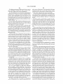
12 Claims, 11 Drawing Sheets
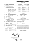
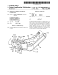
30
)/
Digital Camera
32
.
wurkziatron
Calibration Data
Generator
3_3
illumination
Driver
cg
46
I,’:\ 48 d_/;\ \
Button
Module
Controller
36
US. Patent
Aug. 27, 2013
Sheet 1 0f 11
US 8,519,949 B2
19
/
PDSITIONER
5°
°i
I
l
i
12
1
i
i
i
E
'53 _______________ _ J21
LOCK
Link
Clear
FIG. 1
US. Patent
Aug. 27, 2013
Sheet 2 0f 11
US 8,519,949 B2
22
24
215:1
2F
Centraller
User
Interface
29
FIG. 2
US. Patent
Aug. 27, 2013
Sheet 3 0f 11
US 8,519,949 B2
'i l amr
Dialog;
ea
Workstation
\
35.
1
J
a
Calibration Data
Generator
33
l
illumination
Driver
35
’
‘
FIG. 3
Controller
US. Patent
Aug. 27, 2013
Sheet 5 0f 11
Drive light seumes
‘
~/
74
Capture illumination data J
Generate calibration
V
data J
Store caiinratinn
‘If
data
J
FIG. 5
Detect caiibrated light E2
SUUTCBS
Determine calibration 24
data
‘
_
"
Dnvehehtseurces
FIG. 6
as
J
US 8,519,949 B2
US. Patent
Aug. 27, 2013
Sheet 6 0f 11
US 8,519,949 B2
90
/
Baum,
n hits
g+llcc
Cumparator
92
95L i A
96
f’
"m"
LED Driver
Q
Brightness Value
9_4
n hits
FIG. 7
PWM values
(codes, hex}
UXE
I
PWM Sig
PWM c cle
LII-FIFE lgavvtw
Reference signal
+
film)
0x0
Sesired PWM value
__
H Average value
PWM Butput
—
8X5
UFF
Reference signal
lpyramirll
*
Uxl] q‘u'f
> Time
{3N
+
M
PWM Output M.
M Average value
Desired PWM value
H“ HI > Time
91“
OFF
FIG. 8
US. Patent
Aug. 27, 2013
Sheet 7 0f 11
.NI2;;O2Hm: ,\w1/u2:?‘SE528935 8
w:Eamw8:29am1. ,
£6
$253$3521|.15
/[1
aSQ3Q5mE dSm5:iam \1
2%,“:WWWWEmimigwm5ag%?,
aw?
25,:
25:52
o2 4/
215E:m:53 5
US 8,519,949 B2
2.619: xuml :
m.UHH
US. Patent
DXE
Aug. 27, 2013
Sheet 8 0f 11
_
_,
_
J‘! 1H H
1_
0x0
1
l
"
I 1F] M
_
Average
[-
US 8,519,949 B2
_
___~
_ Reference Si Rai
_.
m
__
_
DeSireR PW
_
value
= Time
0N
—*
—
——
~
"OFF
FIG. 10
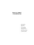
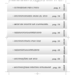
12S
’/
122
, ......
AUTO
SELF
5
BURD BDRD
126mli WT
PSI CHR
KEY émv MASK
1
¥LY
MRS
P1:
2
3
4
128*“ SEL
SEL
SEL
SEL
may cu?
cu?
CUT
CUT
/—136
132-~\_.@
@
EU
33 B ‘M133
134*» ¥RANS
TRANS
TRANS
TRANS
FIG. 11
value
US. Patent
Aug. 27, 2013
m52%; sEma; i:\\
5EN.WE 2:
Sheet 9 0f 11
/ /2:
2512m.,
US 8,519,949 B2
3
P:
.
\mE
, m2
NEEmmy
sENE325EaU?m%;
2EDma6:N52?E?
a3;a;OE22E:2
amm?
\
5%NE5
5:EQ5gE /ZEEaM>52Q5E2WEF
NE/
_:\m
EEQNE2:ZQ5E2W
f
US. Patent
Aug. 27, 2013
Sheet 10 0f 11
US 8,519,949 B2
US 8,519,949 B2
1
2
VIDEO PRODUCTION SWITCHER PANEL
AND RELATED METHODS
Additionally, the color choices are limited to those made by
the manufacturer of the control panel and may not be aestheti
cally pleasing to the end user.
CROSS-REFERENCE TO RELATED
APPLICATION
Another method to aid in the identi?cation of buttons in a
dark environment, such as a television control room, is the use
of button illumination, using one or more light sources per
The present application claims the bene?t of US. Provi
sional Patent Application Ser. No. 60/907,665, ?led on Apr.
13, 2007, and entitled “VIDEO PRODUCTION SWITCHER
PANEL”, the entire contents of Which are incorporated herein
button. This illumination may be used to highlight active
functions or as an overall backlight to improve readability of
button legends. Some implementations alloW adjustment of
button light source(s) brightness. This illumination is typi
by reference.
cally limited to one color, or a small number of color choices
as dictated by the capabilities of the buttons’ light source(s)
FIELD OF THE INVENTION
broadcast audio/video production industry and in particular
and indicators installed on the control panel. This, disadvan
tageously, is limited to the color choices set out by the manu
facturer and may not be aesthetically pleasing to the end user.
It can also increase costs, because of the circuitry needed to
to tactile control panel surfaces.
drive each indicator independently.
This invention relates generally to the professional and
BACKGROUND
Delegation of a Joystick
Video production sWitchers are capable of generating
many effects and require a large number of parameters to be
set and modi?ed by the operator. A multi-axis joystick is a
convenient Way of adjusting these parameters. Traditionally
20
are subject to variation by the nature of their manufacture.
This can result in the unpleasant effect of loW color unifor
mity, due not only to technological limitations of currently
25
sources With a similar but imperfectly matched color are lit,
cost and inherent limitations.
30
indicate Which function is being controlled by the joystick.
Multiple functions may be delegated simultaneously by
selecting multiple buttons. These multiple buttons may then
illuminate simultaneously to indicate the functions being
simultaneously controlled by the joystick. For a modern
35
sWitcher With a large number of controllable items, an equally
large number of buttons and lamps are required.
This approach has many draWbacks. A large amount of
panel real estate is Wasted in providing a button for each
controllable function. It becomes impractical to provide a
available light sources, but also to the sensitivity of human
vision to detect subtle color differences, When many light
side-by-side. Using tighter color tolerance light sources is not
a feasible option in many implementations, due to their higher
the control panel surface of a video sWitcher has an area
dedicated to the joystick and contains a large number of
buttons and lamps. The buttons are used to delegate the joy
stick to control a single particular function. The lamps light to
Color Uniformity
Lighted indicators, such as Light Emitting Diodes (LEDs),
Uniform color and brightness of lighted indicators can also
be signi?cant for proper operation of a control panel. For
example, a green indicator could indicate “All OK”, Whereas
a yelloW indicator might indicate “Caution”. If the indicators
are improperly calibrated, it is possible that an indicator
Which the panel had driven to be lit as green Would actually
appear yelloW, resulting in an operator misinterpreting the
indicator and not taking an appropriate action.
Control of Indicator Brightness Using Pulse-Width Modula
tion (PWM)
40
One common method of controlling the brightness of light
button for each function on the sWitcher that can be controlled
sources such as LEDs is through the use of PWM, Which is
by the joystick. This leads to buttons that serve dual purposes
or functions that cannot be easily selected for control. Sec
cycles the voltage or current feeding a light source ON and
commonly knoWn in the electronics industry. This method
OFF rapidly to simplify the driver circuits. By varying the
ondly, in live production situations Where speed and accuracy
of operation is critical, it can be dif?cult for the operator to
45
relative time the voltage or current is ON versus OFF, the
quickly assess Which function is being controlled by trying to
human eye perception of brightness may be controlled. For
identify a lit button or buttons in a large grouping of buttons.
Dual-purpose buttons or functions Without dedicated buttons
complicate the matter and make it dif?cult to operate the
joystick With certainty of Which parts or characteristics of a
example, a light source that is ON 100% of the time Will
appear to the human eye to be brighter than a light source that
toggles quickly enough, and is ON for 50% of the time and
50
video scene Will be modi?ed.
Identi?cation of Button Groups on a Panel
On a control surface With a multitude of buttons and indi
cators, such as a production sWitcher panel, it is desirable to
alloW an operator to easily identify buttons and to logically
group buttons having related functions, and do so quickly.
This has been done using several methods.
Firstly, physical locations of buttons and button groups can
55
time” versus “OFF time”.
60
and buttons for “memory” could be grouped in a separate
area. This has the disadvantage that once the control panel has
been designed, the groupings are ?xed and do not alloW for
groups of related functions. This has similar disadvantages in
that the colors are ?xed and cannot be quickly changed.
One disadvantage of this scheme is the PWM frequency
has to be quite high (more than 200 HZ) to prevent discomfort
to the human eye (a subtle “?icker”, particularly noticeable
When many light sources located sided by side are turned ON
and OFF at the same time). One approach to reduce this effect
is to increase the refresh frequency, but this makes the control
future functionality enhancement.
Colored button caps have also been used to delineate
during the cycle. This alloWs the perceived brightness of the
light source to be varied by manipulating the amount of “ON
delineate different functional areas of a control panel. For
example, buttons for “keyer control” can be grouped together,
OFF the other 50%.
Existing methods to generate PWM produce a Waveform
With a continuous ON time, and minimum transitions per
cycle. Once a light source is turned ON, a monotonic digital
counter Will turn it OFF at a pre-programmed point in time
65
and poWer circuitry more complex and expensive. Another
option trades off refresh frequency for PWM resolution (the
minimum ON time change possible, given the siZe and incre
ment step of the counter).
US 8,5 19,949 B2
4
3
Identi?cation of Key Types
In some embodiments, the one or more key functions com
One of the primary features of a switcher is called a keyer.
A keyer layers one piece of video, called a key, on top of
another. A good example of this is the placement of the name
prise functions that are accessible through respective further
buttons provided on the video production sWitcher panel.
of a neWscaster on top of live video of that neWscaster. There
indication of the one or more linked functions.
are several different types of keys, including linear, lumi
nance, auto select, chroma, Preset Pattern, and Over The
Shoulder (OTS) boxes, for example. The operator of a
sWitcher panel or sWitcher chooses Which type of key is to be
used. The operator may have many keys available for use
simultaneously, often more than 12. It is very important for
the operator to be able to quickly verify that the correct key
type has been selected on every keyer.
In some embodiments, the module includes a Clear button
operable to release the one or more linked functions from
The module may also include a display for providing an
control by the user controllable input device. A Lock button
may be provided to prevent automatic delegation of the user
controllable input device after the one or more functions have
been linked With the user controllable input device.
According to another aspect of the invention, a video pro
duction sWitcher panel includes a plurality of user operable
buttons, a respective multicolor lighting arrangement oper
able to illuminate each button of the plurality of buttons, and
SWitchers have one button per key type selectable on the
control panel for a selected keyer. One and only one of these
a controller operable to control at least one of a color and an
buttons Will be lit at any time showing the currently selected
intensity of each multicolor lighting arrangement.
key type. Pressing another key type button changes the key
Each multicolor lighting arrangement may include inde
type to the neW selection and lights that button.
Given a large panel With many keys and many key types, it
20
is both space and cost prohibitive to provide one button per
In some embodiments, the controller is operable to illumi
nate groups of the buttons in respective unique colors.
The controller is implemented in softWare in some embodi
keyer per type. For example, a sWitcher With 12 keyers that
each support 5 key types Would require 60 buttons in this
con?guration. SWitchers often place one set of key type but
tons beside a set of buttons to select the keyer to modify. This
ments.
25
user to see the key type state for one keyer at a time. Verifying
lighting arrangement.
that all key types are correct Would require 12 button presses
Respective covers releasably secured to one or more of the
in the case of a 12 keyer sWitcher.
30
Almost all sWitchers have a large graphical display to assist
the operator in using the product. These displays provide
access to menus, one at a time, that shoW the state of controls
as Well as alloWing the user to change these values. Since
sWitchers are often used in a very fast live environment, every
second counts for an operator. A menu that is currently being
35
The plurality of buttons may include calibrated buttons for
Which the multicolor lighting arrangement has been cali
at least one of a color and an intensity of the multicolor
lighting arrangement of each of the calibrated buttons by
driving the multicolor lighting arrangement based on its cali
might be explicitly chosen by the user, sometimes through
40
tively, by pressing certain buttons on the main control panel
surface, a user may cause, as a secondary effect from the
button being pressed, the display to load a particular menu.
Fixed Panel Layout
Traditional sWitcher panels tend to be designed Without
?exibility in mind. Once the product is available to the cus
tomers, the form-?t of the control panel is ?xed. If a customer
Wants the arrangement to be slightly different, the entire panel
Will have to be re-designed.
buttons may also be provided, With each cover having a struc
ture for providing a tactile indication of a delineation betWeen
groups of the buttons. The structure may be a dimple on the
button cover, for instance.
brated. In this case, the controller may be operable to control
displayed on a sWitcher is chosen in one of tWo Ways. A menu
several button presses for navigating a menu tree. Alterna
The video production sWitcher panel may also include a
user input device for receiving from a user a selection of the
at least one of a color and an intensity of each multicolor
reduces the number of buttons required but only alloWs the
Graphic Display
pendently controllable red, green and blue Light Emitting
Diodes (LEDs).
45
bration.
Where the plurality of buttons include calibrated buttons of
a button module, Which further includes a memory for storing
calibration data associated With the multicolor lighting
arrangement of each calibrated button, the controller may be
operable to control at least one of a color and an intensity of
each multicolor lighting arrangement by accessing the cali
50
bration data stored in the memory and driving the multicolor
lighting arrangement based on its calibration.
Another aspect of the invention provides apparatus that
includes an illumination driver that drives a plurality of light
SUMMARY OF THE INVENTION
sources under common driving conditions, and a calibration
Thus, there remains a need for improved apparatus and
methods relating to various aspects of video production and
data generator that receives illumination data associated With
the plurality of light sources driven by the illumination driver
and generates calibration data for the plurality of light sources
video production sWitcher panels.
55
tively coupled to the calibration data generator, that captures
the illumination data and provides the captured illumination
data to the calibration data generator.
button operable to link one or more of a plurality of key
functions of the video production sWitcher panel With the user
controllable input device. The user controllable input device
is operable to control the one or more linked functions of the
video production sWitcher panel.
based on the received illumination data.
The apparatus may also include a capturing device, opera
According to an aspect of the invention, there is provided a
module for a video production sWitcher panel. The module
includes a user controllable input device, and a single Link
60
The capturing device may be one or more of: a digital
camera, a video camera, a scanner, and discrete color sensors,
for example.
In some embodiments, the plurality of light sources
The user controllable input device may include one or more
includes sets of light sources in respective multicolor lighting
of: a joystick, a mouse, a trackball, a keypad, a touchpad, a 65 arrangements for illuminating buttons of a video production
knob, 3D gloves, 3D knobs, a barcode reader, and a Radio
Frequency Identi?cation (RFID) reader.
sWitcher panel button module. If the button module further
includes a button module controller for controlling the mul
US 8,519,949 B2
5
6
ticolor lighting arrangements, the illumination driver may
drive the plurality of light sources indirectly through the
In some embodiments, the scale factors for the green and
blue light sources are determined according to:
button module controller. The button module may also
include a memory, in Which case the calibration data genera
tor may Write the generated calibration data to the memory.
Such an apparatus could be implemented, for example, in a
a
video production sWitcher panel that also includes the plural
ity of li ght sources, and an illumination controller, operatively
coupled to the plurality of light sources, that drives each light
a
_
green —
Gideal / R ideal
i,
Gmeasured / Rmeasured
Bideal / Rideal
blue = i,
Bmeasured / Rmeasured
source according to its calibration data generated by the cali
bration data generator.
According to yet another aspect of the invention, a method
Where
involves driving a plurality of light sources under common
the calibration data comprises intensities Rmeasured’
Gmeaswed, Bmeaswed of the red, green, and blue light sources;
agreen 5
driving conditions, capturing illumination data associated
With the plurality of driven light sources, and generating
and
calibration data for the plurality of light sources based on the
Rideal, Gideal, Bideal are intensities in Which the red, green,
captured illumination data.
Capturing may involve capturing an image of the plurality
of light sources.
In some embodiments, the plurality of light sources
and blue light sources are to be present to achieve the target
color.
20
includes sets of light sources in respective multicolor lighting
arrangements for illuminating buttons of a video production
sWitcher panel button module, the button module further
includes a memory, and the method also includes Writing the
generated calibration data to the memory.
The method may also include driving each light source of
sWitcher panel.
A method according to a still further embodiment of the
25
30
A further aspect of the invention provides apparatus that
includes a plurality of calibrated light sources, and an illumi
light sources in respective multicolor lighting arrangements
for illuminating buttons of a video production sWitcher panel
invention involves determining calibration data associated
With each light source of a plurality of calibrated light
sources, and driving each light source according to its cali
bration data.
The plurality of calibrated light sources may include sets of
light sources in respective multicolor lighting arrangements
for illuminating buttons of a video production switcher panel
button module. Where the button module further includes a
nation controller, operatively coupled to the plurality of cali
brated light sources, that determines calibration data associ
ated With each light source and drives each light source
according to its calibration data.
The plurality of calibrated light sources may include sets of
The apparatus may be implemented, for example, in a
sWitcher panel, With the illumination controller being further
operable to detect installation of the button module in the
the plurality of light sources according to its calibration data.
Such a method may be implemented in instructions stored
on a computer-readable medium, for instance.
ablue are the scale factors for the green and blue light
sources;
memory storing the calibration data, determining may
35
involve reading the stored calibration data from the memory.
Driving may involve driving each light source in a group of
the multicolor lighting arrangements by calculating amounts
of compensation to apply to a driving parameter of each light
40
source in the group to make the group display a target color,
and driving each light source in the group based on a respec
button module. Where the button module further includes a
tive compensated driving parameter.
button module controller for controlling the multicolor light
ing arrangements, the illumination controller may drive each
light source indirectly through the button module controller.
In some embodiments, the set of light sources in each
multicolor lighting arrangement includes a red light source, a
green light source, and a blue light source. Calculating may
In some embodiments, the button module further includes
a memory storing the calibration data, and the illumination
45
and blue light sources relative to the red light source, and the
method may further include applying the respective scale
factors to the driving parameters of the green and blue light
controller determines calibration data by reading the stored
calibration data from the memory.
The plurality of calibrated light sources may include sets of
light sources in respective multicolor lighting arrangements,
50
55
parameter.
tons, and a memory storing calibration data associated With
each calibrated light source.
There is also provided a Pulse-Width Modulation (PWM)
controller that includes a pseudo-random number generator,
and a comparator operatively coupled to the pseudo-random
The set of light sources in each multicolor lighting arrange
ment may include a red light source, a green light source, and
a blue light source, in Which case the illumination controller
sources. The scale factors for the green and blue light sources
may be determined as described above.
Another aspect of the invention provides an illuminated
button module that includes a plurality of buttons, respective
calibrated light sources that illuminate the plurality of but
as noted above. The illumination controller may drive each
light source in a group of the multicolor lighting arrange
ments by calculating amounts of compensation to apply to a
driving parameter of each light source in the group to make
the group display a target color, and driving each light source
in the group based on a respective compensated driving
then involve calculating respective scale factors for the green
number generator and operable to compare a number output
60
by the pseudo-random number generator With a threshold,
and to provide an output at a ?rst level or at a second level
may calculate the amounts of compensation for each multi
depending on the comparison.
color lighting arrangement of the group by calculating
The pseudo-random number generator may have a range,
and be operable to output every number in the range once
Within a refresh cycle.
In some embodiments, the pseudo-random number genera
tor is a Linear-Feedback Shift-Register (LFSR).
respective scale factors for the green and blue light sources
relative to the red light source, and apply the respective scale
factors to the driving parameters of the green and blue light
sources.
65
US 8,519,949 B2
8
7
A PWM controller may be implemented, for example, in an
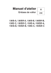
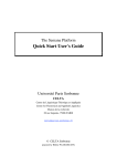
FIG. 1 shoWs an example of an enhanced user input device
LED driver, in Which case the ?rst level may cause an LED to
turn ON, and the second level may cause the LED to turn OFF.
Such a PWM controller might also be implemented in a
control area.
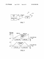
FIG. 2 is a block diagram of an example button group
illumination control apparatus.
video production sWitcherpanel, Which includes a plurality of
user operable buttons, an LED arrangement for illuminating
each button of the plurality of buttons, and respective LED
drivers operatively coupled the PWM controller and to each
LED arrangement for driving each LED arrangement. The
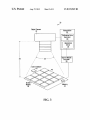
FIG. 3 is a block diagram of a light source calibration
system according to another embodiment of the invention.
FIG. 4 is a block diagram of a system incorporating cali
brated light sources, in accordance With a further embodiment
of the invention.
FIGS. 5 and 6 are How diagrams illustrating methods relat
ing to calibrated light sources.
FIG. 7 is a block diagram of a conventional PWM control
ler.
?rst level causes an LED driver to turn an LED ON, and the
second level causes an LED driver to turn an LED OFF.
In some embodiments, the respective LED drivers are
operatively coupled together in a chain, and the PWM con
troller is operatively coupled to the chain and operable to
control the respective LED drivers.
A memory may also be provided in the video production
FIG. 8 shoWs example plots relating to PWM generation
using a monotonic counter With 4 bits resolution.
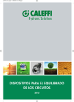
FIG. 9 is a block diagram of a light source driving arrange
ment that includes a PWM controller according to an embodi
ment of the invention.
sWitcher panel for storing respective thresholds for a plurality
of brightness levels, in Which case the PWM controller reads
a threshold for each of the respective LED drivers from the
memory.
In accordance With a further aspect of the invention, a keyer
module for a video production sWitcher panel includes a
display for providing an indication of a source of a key cur
rently associated With the keyer and an indication of a type of
FIG. 10 shoWs an example plot relating to PWM generation
20
FIG. 11 shoWs an example keyer module incorporating
another embodiment of the invention.
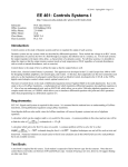
FIG. 12 is a top vieW of an example video production
the key.
The indication of the type of the key comprises an icon in
some embodiments. A location of the icon in the display may
be indicative of the type of the key.
According to yet another aspect of the invention, a video
production sWitcher panel system includes a display having a
?rst display for providing access to a full menu system of a
video production sWitcher panel, and a second display area
sWitcher panel.
25
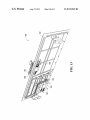
FIG. 13 is a perspective vieW of an underside of an example
video production sWitcher panel.
FIG. 14 is a block diagram shoWing an example dual menu
display.
30
for providing access to at least a portion of the full menu
system.
The ?rst display area may incorporate user input devices,
and the second display area may comprise duplicate user
input devices associated With the portion of the full menu
system to Which the second display area provides access.
In some embodiments, the duplicate user input devices
using a controller of the type shoWn in FIG. 9.
DETAILED DESCRIPTION OF PREFERRED
EMBODIMENTS
Improved Delegation of Functions
35
comprise programmable knobs.
An example of an improved user input device control area
is illustrated in FIG. 1. The example control area of a posi
tioner 10 shoWn in FIG. 1 includes a status display 12, a
Joystick 14 as an example of a user controllable input device,
a Lock button 16, a Link button 18, and a Clear button 19.
It should be appreciated that the joystick 14 is shoWn in
The video production sWitcher panel may include one or
more user input devices Which, When operated, cause a menu 40 FIG. 1 solely for illustrative purposes. Other embodiments of
change on at least one of the ?rst display area and the second
the invention may be implemented in conjunction With dif
display area.
ferent input devices, such as a mouse, a trackball, a keypad, a
The ?rst display area and the second display area may
touchpad, knobs, 3D gloves, 3D knobs, a barcode reader, a
enable one or more of a copy function to copy a menu from
one display area into the other display area, and a sWap
Radio Frequency Identi?cation (RFID) reader, etc.
45
function to sWap a menu betWeen the tWo display areas.
At least one of the ?rst display area and the second display
area may also provide access to a user manual of the video
may include further, feWer, or different elements, arranged
production sWitcher panel.
A video production sWitcher panel is also provided, and
includes a panel structure, and a plurality of button modules
carried by the panel structure, at least one of the button mod
and/or interconnected in a similar or different manner, than
50
button can be used to provide the same functionality as mul
55
some embodiments.
Other aspects and features of embodiments of the present
invention Will become apparent to those ordinarily skilled in
the art upon revieW of the folloWing description.
ing draWings.
tiple delegation buttons, as described beloW. The multi-line
display 12 has also been incorporated into the positioner 10
control area, eliminating the need for lamps to display status.
To understand one method of operation of the joystick 14,
a concept knoWn as auto-folloW is ?rst described. A video
60
BRIEF DESCRIPTION OF THE DRAWINGS
Examples of embodiments of the invention Will noW be
described in greater detail With reference to the accompany
explicitly shoWn in the draWings.
According to an aspect of the invention, separate delega
tion buttons that might typically be found in a joystick control
area have been replaced With the single Link button 18. This
ules being interchangeable in the panel structure Without
displacing other button modules in the panel structure.
The video production sWitcher panel may also include
cables interconnecting the button modules, and a detector for
detecting a type of each button module of the plurality of
button modules. The detector is implemented in software in
Thus, the contents of FIG. 1, as Well as all other Figures
shoWing embodiments of the invention, are thus intended to
be illustrative and not limiting. Embodiments of the invention
65
sWitcher panel contains many buttons dedicated to perform
ing speci?c functions. Many of these functions have param
eters that are adjustable by the joystick 14. For example,
performing a Fly Key Will alloW the joystick 14 to move or
rotate an image on screen. When a Fly Key button (not shoWn)
on a sWitcher panel is pressed, the joystick 14 Will automati
cally sWitch to control the Fly Key operation. This eliminates
the need for dedicated delegation buttons and saves time by
US 8,519,949 B2
10
performed. It is also possible to lock the joystick 14 When it
not requiring the operator to hit multiple buttons to both
enable a function and delegate control of it to the joystick 14.
A joystick 14 that automatically changes its delegation based
has no control of any function. This gives the operator peace
of mind that bumping or moving the joystick 14 Will not make
on other buttons being pressed leads to an increased need for
any changes to any system parameters.
quick and accurate display of What is currently being con
Thus, in summary, a module for a video production
sWitcher panel may include a user controllable input device,
the joystick 14 in the example 10, and a single Link button 18
trolled.
One embodiment of the present invention uses the multi
line character display 12 to shoW textual information on the
current joystick assignment. This replaces the status that Was
that is operable to link one or more key functions of the video
production sWitcher panel With the user controllable input
previously shoWn using lamps. The text display 12 is gener
device.
Improved Identi?cation of Button Groups on a Panel
One method of button illumination according to another
aspect of the invention is referred to as “Themable Panel
ally faster to read and provides more ?exibility in the kind of
information that can be displayed. For example, if the j oystick
14 is delegated to controlling a Digital Video Effects (DVE)
channel, the display 12 can indicate Whether it is adjusting
GloW”, and improves on the existing approaches of button
position or rotation. This information Was previously not
available Within a joystick area and needed to be found else
Where on a control panel. With the multitude of features
identi?cation.
By use of independently controllable red, green and blue
light sources such as LEDs underneath each button and indi
cator, each button and indicator may be independently illu
available on today’s video production sWitchers, the ability to
display dynamic information provides feedback to the user
that Was not possible With the ?xed nature of lamps.
The Link button 18 alloWs an operator to use the joystick 14
to control multiple functions at the same time. By holding
doWn the Link button 18 and performing any other function,
including but not necessarily limited to those that Would
normally auto-folloW the joystick 14, the neW function Will be
added to the list of current joystick-controlled functions. For
20
minated in a unique color. This alloWs softWare, for example,
to group related functions by illuminating them in a similar
color. This also, advantageously, alloWs any grouping of
functions to be achieved by simply providing softWare, for
example, to control the desired groupings as desired. Colors
25
and/or other characteristics such as illumination levels for
button groups may be selectable by an operator through a user
example, if the joystick 14 is currently controlling the color of
interface such as a menu system displayed on a touchscreen or
a background matte, and the operator holds the Link button 18
and presses a Fly Key button (not shoWn) on the control panel
to Which the positioner 10 is connected, the joystick 14 Will
then be controlling both of those functions (i.e., they are
other user interface device.
Some examples of groupings on a sWitcher control panel
30
Each Multi-Level Effects (MLE) or Mix-Effects
linked together). As the joystick 14 is moved, each function
receives motion events from it, and performs the normal
action for that function Without knoWledge that any other
function is likeWise being controlled. The link Will persist
until the joystick 14 is assigned to control another function or
the link is explicitly cleared using the Clear button 19.
bank is grouped With a common color
Each Crosspoint bus is grouped With a common color
35
Related macro buttons are grouped With a common color
Related input crosspoint buttons are grouped With a com
mon color
On-air items are highlighted in a speci?c color
The actual manner in Which motion events are provided to
a control panel need not vary substantially from presently
available sWitcher panels. Although embodiments of the
invention provide a different mechanism for delegating func
are as folloWs:
Disabled items are illuminated in a common color.
40
This approach advantageously alloWs colors to be selected
by the user, and hence alloWs a color theme to be selected that
tions to a joystick or other user controllable device, the opera
is aesthetically pleasing by that user.
tive coupling betWeen such device and other components of a
control panel may remain virtually the same. Once functions
illumination control apparatus. The apparatus 20 includes
have been delegated to the joystick 14, for example, motion
events may be provided to and processed by the sWitcher
panel in much the same Way as in conventional control panels,
even though the functions Were delegated in a different Way,
in accordance With an embodiment of the invention.
The status display 12 above the joystick 14 Will indicate
that multiple functions are linked together. A menu system
can be used to display full details of all current links. It is
FIG. 2 is a block diagram of an example button group
45
a controller 27, and a user interface 29. All of these compo
nents may be implemented in a sWitcher panel. In some
embodiments, the button covers 22, 24 and lighting arrange
50
55
function that Would normally take control of the joystick 14 is
elements, such as a controller in a sWitcher panel and one or
more button module controllers.
Those skilled in the art to Which the present application
pertains Will be familiar With many types of illuminated but
tons that are suitable for use in sWitcher panels. Illuminated
button assemblies may include transparent or at least light
60
transmissive button covers 22, 24 and lighting arrangements
26, 28. Although not explicitly shoWn in FIG. 2 to avoid
overly complicating the draWing, a button assembly Would
also include some sort of sWitch beloW each button cover 22,
24, contacts or leads for connection to other sWitcher panel
function from changing the current joystick delegation. This
is especially useful When multiple links have been set up and
the operator does not Want them to change When another
ments 26, 28 are implemented in one or more button modules,
and the controller 27 and the user interface 29 are imple
mented in a sWitcher panel in Which the button module(s) may
be installed. Although shoWn in FIG. 2 as a single block,
functions of the controller 27 may be provided in multiple
possible for the operator to clear all links by holding the Link
button 18 and pressing the Clear button 19 in some embodi
ments. In theory there is no limit to the number of functions
that can be linked to the joystick 14, although an operator of
a sWitcher panel may decide on a practical or manageable
limit.
Embodiments of this invention can thus provide capabili
ties that Were not possible in the past, such as adjusting the
position and rotation of an image at the same time.
The positioner 10 control area also includes a Lock button
16. The Lock button 16 is used to prevent an auto-folloW
button covers 22, 24, respective lighting arrangements 26, 28,
65
components, and possibly other elements involved in actual
operation of the button to control functions of a sWitcher
panel.
US 8,519,949 B2
11
12
The lighting arrangements 26, 28 are multi-color sources in
and/or color of illumination of the buttons 40 of the button
some embodiment, including red, green, and blue LEDs.
Other types of light sources are also contemplated.
In some embodiments, the controller 27 is implemented in
module 38. Other types of color and/or intensity sensitive
software for execution by one or more processing elements.
As shown, the calibration data generator 33 and the illumi
nation driver 35 may be implemented in a workstation 34 in
one embodiment. More generally, these components may be
instruments may be used instead of a digital camera, such as
a video camera or discrete color sensors, for example.
Microprocessors, Application Speci?c Integrated Circuits
(ASICs), Field Programmable Gate Arrays (FPGAs), and
Programmable Logic Devices (PLDs) are examples of such
provided in software, hardware, ?rmware, or combinations
processing elements. The controller 27, more generally, may
be implemented using hardware, software, ?rmware, or com
thereof.
The button module controller 36 may similarly be imple
mented in software, hardware, and/or ?rmware, and in the
example shown controls illumination of all of the buttons 40
binations thereof.
The user interface 29 is intended to represent one or more
devices for at least accepting user inputs. Examples include a
of the button module 38. Where each button 40 includes
keyboard, a pointing device such as a mouse, and a combined
input/output device such as a touchscreen.
In operation, an operator may select or otherwise enter
multiple light sources, such as red, green, and blue LEDs,
each light source may be controlled individually to provide
any of various colors and intensities for illuminating the but
desired group settings, including the groupings and respec
tons.
tive colors and/or illumination levels for the groupings,
through the user interface 29. The controller 27 drives the
lighting arrangements 26, 28 in accordance with the opera
tor’s entered group settings. The groupings of the buttons will
then be illuminated on the panel with different colors and/or
illumination levels.
Another possible form of delineation between groups of
buttons would be removable button covers 22, 24. Button
covers having structures for providing a tactile indication of a
delineation between groups could be releasably secured to
one or more buttons of a switcher, for example. Dimpled
button covers could be placed on the ?rst and/or last buttons
in columns of buttons that control the same types of inputs, for
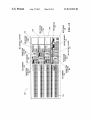
In the system 30, the button module 38 includes sixteen
20
(PCB) in some embodiments. The speci?c number of buttons
provided in a button module may of course vary between
different embodiments of the invention. Those skilled in the
art will be familiar with many types of illuminated button
25
Erasable Programmable Read Only Memory (EEPROM)
30
as one or more light sources, which may or may not be the
22, 24 at button grouping delineation points. The tactile but
35
Thus, as will be apparent from FIG. 2, a video production
switcher panel may include user operable buttons, a multi
color lighting arrangement 26, 28 operable to illuminate each
40
ment. Respective covers 22,24 may be releasably secured to
45
Color Matching
50
times perceived when many multicolor buttons are lit side by
side, using a dedicated set of red/green/blue light sources
(such as LEDs) to independently illuminate each button.
data capturing involves taking a picture of the illuminated
55
example, by a specialiZed software application running in the
to a button module 38. The workstation 34 includes a calibra
60
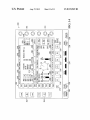
ule 38 includes a plurality of illuminated buttons 40 and a
sensor or capturing device for sensing and capturing the level
workstation 34. Capture control functions may be integrated
into the calibration data generator 33 or provided separately.
The calibration data generator 33 of the workstation 34
receives the picture, or more generally captured illumination
data, from the digital camera 32. The illumination data is in
operatively coupled to the digital camera 32. The button mod
The digital camera 32 is an example of an illumination
all of aperture, lens model, focal distance, sensitivity, expo
sure time, noise reduction settings, ambient lighting, camera
to button module distance 46, button module position in the
?eld of view 48 of the camera, etc., and may be controlled, for
operatively coupled to the digital camera, and a button mod
ule controller 36 operatively coupled to the workstation and
memory 42. A color standard 44 is also provided.
30, captures illumination data under standardized capture
buttons 40 of the button module 38. The capture conditions
under which illumination data is captured may include any or
The system 30 includes a digital camera 32, a workstation 34
tion data generator 33 and an illumination driver 35 opera
tively coupled to each other and to the button module con
troller 36. The calibration data generator 33 is also
driving the light sources of all of the buttons simultaneously,
although it is also possible to drive the light sources of only a
conditions. In the case of the digital camera 32, illumination
FIG. 3 is a block diagram of a light source calibration
system according to another embodiment of the invention.
the button module 38, the buttons 40 of the button module are
driven by the illumination driver 35 under common driving
conditions. According to one embodiment, each button 40
includes one red light source, one green light source, and one
blue light source, and all of these light sources are driven
using the same PWM settings. All of the buttons 40 of the
button module 38 may be calibrated at the same time by
subset of the buttons at any time.
A capturing device or illumination sensor that is sensitive
to one or more of color and intensity, and may be a high
resolution device such as the digital camera 32 in the system
A further aspect of the invention provides a cost effective
and ?exible mechanism to analyZe a set of multiple light
sources, such as those in a button module for instance, and to
compensate for color variations. Such variations are some
same type as those provided in the buttons 40 of the button
module 38.
In operation, after manufacturing and possibly testing of
friction ?t or other means.
one or more of the buttons, and in some embodiments the
button covers include structures for providing a tactile indi
cation of a delineation between groups of the buttons.
device in one embodiment. Other types of memory devices
may also or instead be used.
The color standard 44 may be implemented, for example,
tion could replace or be installed over standard button covers
button, and a controller 27 operable to control at least one of
a color and an intensity of each multicolor lighting arrange
assemblies. Any of many different types of memory devices
may similarly be used to implement the memory 42, although
a solid state memory device might be most appropriate for
this purpose. For example, the memory 42 is an Electrically
instance, to separate live camera inputs from stored inputs.
Thus, button covers including some sort of tactile indica
ton covers might be releasably secured to buttons through a
illuminated buttons 40 and a memory 42, all of which may be
installed on a single button module Printed Circuit Board
65
the form of a picture in RAW format in one embodiment. The
received illumination data, an image in this example, is pro
cessed by the calibration data generator 33 to determine the
US 8,519,949 B2
13
14
location and color composition of every lit button 40 in the
image. Determining color composition in the case of multi
Whose output light levels do not satisfy previously-deter
color light sources might involve determining the relative
brightness of the related red, green, and blue light sources, for
example. At least the measured relative brightness of each
resentation of a certain color range. This alloWs a single
mined acceptable criteria, such as overall brightness, or rep
operation to calibrate indicators, verify the light outputs of the
indicators, and verify the circuitry Which drives the indicators
in a single operation.
light source for each button is Written into the memory 42 as
calibration data by the calibration data generator 33, through
Variations of the example system 30 and the mechanism
described above are contemplated. For example, although an
image in RAW format is described above, other formats may
instead be used. RAW and other “native” camera image for
mats may provide su?icient resolution of illumination data
the button module controller 36 in the example shoWn.
In some embodiments, red is selected as a reference color
for the purposes of calibration and adjusted driving, as
described in further detail beloW. Other colors or a separate
emissive color standard 44, photographed at the same time as
the button module 38, could be selected as a reference as Well,
for subsequent generation of calibration data, and may also
avoid interference from many post-processing options a digi
tal camera typically has, Which could bias capture results. In
With its illumination data also being processed to generate
general, formats having high channel resolution (number of
bits per primary color, R,G,B), illustratively 12 bits or higher,
may provide better illumination data capture and calibration
results, although other formats such as the Joint Photographic
Experts Group (JPEG) format having only 8 bits per channel
reference calibration data to be Written to the memory 42.
Other information might also be included in the calibration
data that is Written to the memory 42 by the calibration data
generator 33. For example, the calibration data generator 33
might also determine the type of the button module 36, illus
tratively by receiving user inputs through a user interface of
the Workstation 34, and Write an indication of the determined
type to the memory 42. This might not be done, for example,
Where a type indicator is already stored in the memory 42
during manufacture or testing. An identi?er of the digital
camera 32, the driving conditions, and/or the capture condi
tions may also be included in the calibration data that is
20
25
Graphic Interchange Format (GIF).
Thus, FIG. 3 represents one example of an apparatus that
includes an illumination driver 35 that drives light sources
under common driving conditions, and a calibration data
Written to the memory 42 of the button module 38.
A calibration mechanism supported by the system 30 pro
vides several key advantages. For example, all of the light
sources in the button module 38 can be simultaneously cali
could potentially be used. Results for loWer resolution for
mats might be improved through ?ltering and/or otherWise
processing color information. Further possible illumination
data formats include, for example, Tagged Image File Format
(TIFF), Portable Network Graphics (PNG) format, and
30
generator that receives illumination data associated With the
light sources driven by the illumination driver and generates
brated, thereby dramatically reducing the processing time per
calibration data for the light sources based on the received
module. In addition, common off the shelf image capture
illumination data. A capturing device, in the form of the
digital camera 32 in the example shoWn, captures the illumi
nation data and provides the captured illumination data to the
devices, such as digital cameras, video cameras, and scanners
may be used to capture illumination data. Such a mechanism
may also have a loWer cost and higher speed than existing
application speci?c discrete sensor arrays that typically
35
in respective multicolor lighting arrangements for illuminat
ing the buttons 40. Although indirect driving of the button
include customiZed jigs With multiple sensors or ?bers to
carry light from each button into a common sensor.
Other advantages may also be inherent in light source
calibration as disclosed herein. Conventional calibration
40
techniques typically require manual inspection of indicators
using some form of electronic sensor or even subjectively by
eye. Manual or mechanical adjustment of light sources is then
required on a per-unit basis to attempt to match the colors
adequately. These methods are sloW and error-prone.
FIG. 3 and the foregoing description thereof relate to cali
bration of button modules. FIG. 4 is a block diagram of a
system incorporating calibrated light sources, in accordance
45
sating for differences. This is much faster and much more
50
A further advantage is that subsets of a sWitcher panel can
be calibrated independently. Smaller areas of buttons can be
calibrated independently of other groups. Thus, When a com
large, and accordingly it may be impractical to calibrate it all
at once. Additionally, if a portion of the sWitcher panel fails,
either in the factory or subsequently after being shipped to an
55
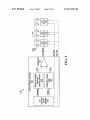
buttons 58, 64.
The user interface 52, like the user interface 29 (FIG. 2)
operator and possibly also providing outputs to the operator.
The button modules 54, 60 and the module controllers 66, 68
may be the same as the button module 38 and the button
60
The calibration techniques proposed herein also advanta
geously provide the ability to perform a diagnostic on a unit
system employed in a calibration system, for example, can be
programmed to reject indicators that are not functioning, or
controller. The panel CPU 69 is operatively coupled to the
may include one or more devices for receiving inputs from an
end user, it is possible to replace a smaller subsection of the
panel With a neW, previously calibrated subsection.
containing one or more indicators automatically. A softWare
With a further embodiment of the invention. The system 50
includes a user interface 52, multiple calibrated button mod
ules 54, 60 With associated module controllers 66, 68, and a
panel Central Processing Unit (CPU) 69 as an example of a
component that could be used to implement an illumination
user interface 52 and to the button module controllers 66, 68,
Which are also operatively coupled to the button modules 54,
60. Each button module 54, 60 includes a memory 56, 62 and
plete sWitcher panel is assembled, the calibration of all indi
cators could have been previously completed, so that calibra
tion of the entire panel is not required. This may be
particularly advantageous, since a sWitcher panel may be very
light sources through the button module controller 36 is
shoWn in FIG. 3, an illumination driver may drive light
sources directly or through some other indirect mechanism.
Embodiments of the present invention signi?cantly improve
upon such techniques by capturing illumination data and
generating calibration data, and then electronically compen
accurate than previous techniques.
calibration data generator 33. In the case of the button module
38, the light sources may be arranged in sets of light sources
65
module controller 36 (FIG. 3), although calibration data
Would already have been Written to the memory 56, 62 of each
button module in the system 50.
The panel CPU 69 is intended to represent one possible
implementation of an illumination control function. In many
sWitcher panels, a panel controller is implemented using a
CPU or other type of processor that may reside in the sWitcher
panel itself or in an associated sWitcher frame. HoWever,
US 8,519,949 B2
15
16
embodiments of the invention are in no Way limited to this
determining red, green, and blue scale factors in a similar
manner, although in this case the red scale factor might not
particular implementation of an illumination controller.
In FIG. 4, the panel CPU 69 automatically detects neW
necessarily be 1.
Scale factors and/ or compensated driving parameters may
be “pre-calculated” and stored by the panel CPU 69, When a
button modules installed in a switcher panel. When a neW
button module 54, 60 is detected, the panel CPU 69 reads its
calibration data from the memory 56, 62 via the module
controller 66, 68. The set of light sources for each button 58,
64 can then be driven in accordance With its individual cali
bration data to provide consistent illumination across all but
tons 58, 64 and all button modules 54, 60.
According to one embodiment, each button 58, 64 includes
a set of red, green, and blue light sources, and the panel CPU
69 calculates green and blue scale factors for each button in
each button module 64, 60. In the case of LEDs as the light
sources, red LEDs tend to be the most reliable and stable, and
for this reason only green and blue scale factors might be
calculated in some embodiments. It should be appreciated,
hoWever, that the present invention is not in any Way limited
to adjusted driving of only a subset of a set of light sources.
Individual driving conditions for all light sources in each set
button module 54, 60 is ?rst detected for instance, or in real
time When a button module is to be illuminated.
Since a button module memory 56, 62 stores calibration
data based on measurement results, and not the scale factors
or compensated driving parameters, a scaling or driving
adjustment algorithm can be ?eld updated over time to
improve its performance.
For example, another algorithm might compensate only for
brightness variations. In this case, the scale factors for each
button (ared, agree”, ablue) are chosen so that all light sources
of the same type have the same relative brightness When a
common driving input is used. The relative brightness might
correspond to a selected standard such as 44 (FIG. 3) or to an
20
might be adjusted in other embodiments.
Green and blue scale factors could be determined accord
idealiZed source (i.e., after calibration, all red light sources
should read R0, all green light sources should read GO and all
blue light sources should read BO, if (i,, ig, ib) are used as
inputs.
ing to Equation (1) beloW, for example:
A further example Would entail compensating for bright
25
a
_
green —
01mg =
Gideal / Rideal
(1)
is
Gmeasured / Rmeasured
ness variations on the red component, While keeping the
desired color balance. In this case the per button coef?cients
or scale factors (ared, agree”, ablue) Wouldbe multiplied by the
ratio of an ideal relative brightness Y1. deal to the measured
Bideal / Rideal
Bmeasured / Rmeasured
i ,
relative brightness Ymeaswed for that button. The “brightness”
30
green, and blue components measured during calibration; and
Rideaz, Gideal, Bideal are the ideal intensities that the red,
neers (SMPTE) in one embodiment.
In general, a compensation algorithm may be established
and/or updated to accommodate a Wide variety of target col
35
includes calibrated light sources, for illuminating the buttons
58, 64, and an illumination controller, in the form of the panel
CPU 69, that determines calibration data associated With each
desired target color, illustratively a target White mixing ratio.
40
When a softWare application being executed by the panel
CPU 69 determines that a particular button should be lit With
a color Whose color components’ relative intensities are (r, g,
b), or an illumination color is selected or otherWise entered by
45
an operator through the user interface 52, adjusted driving
parameters are used. Equation (2) beloW provides examples
of adjusted driving parameters:
50
(2)
Such parameters may be Written as values in an LED
brightness table in a button module controller 66, 68 that
controls the button(s) 58, 64 to be illuminated, to compensate
for differences among button lighting arrangements. The par
ors and intensities.
FIG. 4 thus represents an example of an apparatus that
green, and blue light sources must be present in, to achieve a
In the above example, the scale factors are determined to
achieve a target White color. It should be appreciated, hoW
ever, that any other target color could similarly be used as a
basis for determining scale factors or other driving param
eters for calibrated light sources.
is a linear combination of that of each channel (R, G, B), as
de?ned by the Society of Motion Picture and Television Engi
Where
agree”, ablue are the green and blue scale factors;
measured, Gmeaswed, Bmeaswed are the intensities of the red,
55
light source and drives each light source according to its
calibration data. The light sources in this example include sets
of light sources in respective multicolor lighting arrange
ments. A group of the lighting arrangements can be driven by
calculating amounts of compensation to apply to a driving
parameter of each light source in the group to make the group
display a target color, and driving each light source in the
group based on a respective compensated driving parameter.
Although shoWn separately in FIGS. 3 and 4 and described
separately above for the purposes of illustration, it should be
appreciated that both calibration of button modules and use of
calibrated button modules could potentially be supported in a
sWitcher panel. Thus, in one embodiment, button modules are
calibrated prior to assembly of a panel, and the panel enables
multiple separately calibrated button modules to be used
together to provide consistent panel illumination. Other
embodiments in Which the calibration mechanism is also
ticular mechanism through Which adjusted driving param
supported in a panel could provide for periodic or on-demand
eters are provided to calibrated light sources is implementa
?eld re-calibration of button modules to correct for color
variations that may appear over time With ongoing use of
tion dependent. Brightness tables represent one possible light
source driving mechanism. Embodiments of the invention
may be implemented using other mechanisms as Well.
The compensated relative intensities described above also
represent one, but by no means the only, example of driving
parameters that may be adjusted or compensated.
60
As noted above, red is selected as a reference color in some
embodiments. Other colors or an emissive color standard 44
65
(FIG. 3) could instead be selected as a reference and used in
button modules during operation of a panel. Thus, both a
compensation algorithm and calibration data may be updated
in the ?eld.
FIGS. 3 and 4 and the foregoing description relate to appa
ratus embodiments of calibration and compensation. Other
embodiments are also contemplated. FIGS. 5 and 6, for
example, are How diagrams illustrating methods relating to
calibrated light sources.