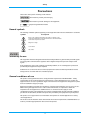
1
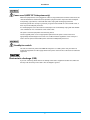
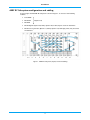
AXRF RF Subsystem and AutoCal Unit
Getting Started
Read this before handling or powering up the instrument!
Contains important safety precautions
Document part no. 47090/303
AXRF RF Subsystem
and AutoCal Unit
Getting Started
© Aeroflex Limited 2015
Longacres House
Six Hills Way
Stevenage SG1 2AN
UK
No part of this document may be reproduced or transmitted in any form
or by any means, electronic or mechanical, including photocopying,
or recorded by any information storage or retrieval system,
without permission in writing by Aeroflex Limited
(trading as Cobham Wireless and hereafter referred to throughout the document as ‘Cobham’).
Document no. 47090/303
Issue 2
27 April 2015
Preface
About this document
This guide covers the AXRF RF Subsystem and the AutoCal Unit.
It contains safety precautions that you should observe before and during operation of the
instruments.
It provides a very basic introduction to the instruments.
For full details of all the capabilities of the instruments, please refer to the AXRF RF
Subsystem and AutoCal Unit User Manual (document no. 47090/270) on the supplied
CD-ROM 46886/100.
ii
Preface
Contents
About this document .................................................................................................................................................. ii
Associated documentation ..............................................................................................................................................iv
Safety instructions ........................................................................................................................................................ v
Invalid cal data/damage to modules ............................................................................................................................v
Precautions ........................................................................................................................................................................vi
Précautions ........................................................................................................................................................................ix
Vorsichtsmaßnahmen .............................................................................................................................................. xii
Precauzioni ...................................................................................................................................................................... xv
Precauciones .............................................................................................................................................................. xviii
Introduction ......................................................................................................................................................................1
AXRF RF Subsystem .............................................................................................................................................................. 1
AutoCal Unit ............................................................................................................................................................................. 1
Installation requirements ........................................................................................................................................ 2
AXRF RF Subsystem cooling............................................................................................................................................. 2
18-slot chassis ................................................................................................................................................................. 2
Connecting to supply........................................................................................................................................................... 2
AXRF RF Subsystem ...................................................................................................................................................... 2
AutoCal Unit ..................................................................................................................................................................... 2
Disconnecting device................................................................................................................................................... 2
AXRF RF Subsystem configuration and cabling ..................................................................................................... 4
Software ...............................................................................................................................................................................5
Required software.................................................................................................................................................................. 5
Software installation ............................................................................................................................................................ 5
Programming the AXRF RF Subsystem ....................................................................................................................... 5
General information ..................................................................................................................................................... 5
AXRF control software ........................................................................................................................................................ 5
AXRF control description ........................................................................................................................................... 5
iii
Preface
Associated documentation
If you want to…
Refer to…
Learn about AXRF RF Subsystem and AutoCal Unit
AXRF RF Subsystem and AutoCal Unit User Manual
Part no. 47090/270
On AXRF System CD-ROM 46886/100 and at www.cobham.com/wireless
iv
Safety instructions
These requirements apply to both the AXRF RF Subsystem and the AutoCal Unit, unless otherwise
specified.
For user safety, read and follow all instructions, WARNINGS, CAUTIONS, and Notes marked in this
manual and on the associated instrument before handling or operating the instrument.
Read these safety instructions carefully.
Keep this manual for future reference.
Read the specifications section of this manual for information about the operating environment of
the instrument.
When installing/mounting or uninstalling/removing an instrument:
turn off power and unplug any power cords/cables.
To avoid electrical shock and/or damage to the instrument:
keep the instrument away from water or liquid sources;
keep the instrument away from high heat or high humidity;
keep the instrument properly ventilated (do not block or cover ventilation openings);
make sure to use recommended voltage and power source settings;
always install and operate the instrument near an easily accessible electrical socket-outlet;
secure the power cord (do not place any object on/over the power cord);
only install/attach and operate the instrument on stable surfaces and/or recommended
mountings;
if the instrument is not to be used for long periods, turn it off and unplug it from its power source.
Never attempt to repair an instrument. Instruments should only be serviced by qualified personnel.
An instrument must be serviced by authorized technicians when:
the power cord or plug is damaged;
liquid has penetrated the instrument;
it has been exposed to high humidity/moisture;
it is not functioning or does not function according to the user manual;
it has been dropped and/or damaged;
it has an obvious sign of breakage.
Invalid cal data/damage to modules
Do not remove any of the installed PXI modules. Removing a module invalidates the system
calibration data supplied with the AXRF RF Subsystem, and may damage the module.
PXI is a trademark of the PXI Systems Alliance
NI and LabVIEW are the registered trademarks of National Instruments Inc.
Product and company names listed are trademarks or trade names of their respective companies.
v
Safety
Precautions
These terms have specific meanings in this manual:
information to prevent personal injury.
information to prevent damage to the equipment.
important general information.
Hazard symbols
The meaning of hazard symbols appearing on the equipment and in the documentation is as follows:
Symbol
Description
Refer to the operating manual when this symbol is marked on the
equipment. Familiarize yourself with the nature of the hazard and the
actions that may have to be taken.
Dangerous voltage
Toxic hazard
Hot surface
Suitability for use
This equipment has been designed and manufactured by Cobham to generate low-power RF signals
for testing radio communications apparatus and to digitize and provide spectrum analysis of RF
signals.
If the equipment is not used in a manner specified by Cobham, or if it is damaged, the protection
provided by the equipment may be impaired.
Cobham has no control over the use of this equipment and cannot be held responsible for events
arising from its use other than for its intended purpose.
General conditions of use
This product is designed and tested to comply with the requirements of BS EN 61010-1 ‘Safety
requirements for electrical equipment for measurement, control and laboratory use’, for Class III
equipment and is for use in a pollution degree 2 environment. The equipment is designed to operate
from an installation category II supply.
Equipment should be protected from the ingress of liquids and precipitation such as rain, snow, etc.
When moving the equipment from a cold to a hot environment, it is important to allow the
temperature of the equipment to stabilize before it is connected to the supply to avoid
condensation forming. The equipment must only be operated within the environmental conditions
specified in the data sheet, otherwise the protection provided by the equipment may be impaired.
This product is not approved for use in hazardous atmospheres or medical applications or safetycritical applications.
The enclosure of the host PXI chassis should meet the enclosure requirements of BS EN 61010-1, in
order to provide an appropriate fire enclosure for the product.
vi
Safety
Electrical hazards (DC supply voltage)
This equipment conforms with IEC safety Class III, meaning that for continued safety it must only
be connected to supplies and signal sources which conform to ‘Separated Extra-Low Voltage’ (SELV
and SELV-E) voltage and insulation requirements. No hazardous voltages are generated internally.
See the data sheet for the maximum permitted voltage levels that can be applied.
Do not remove equipment covers as this may result in personal injury. There are no user-serviceable
parts inside.
Refer all servicing to qualified personnel.
Heavy equipment
The weight of this equipment exceeds the 18 kg (40 lb) guideline for manual handling by a single
person. To avoid the risk of injury, an assessment should be carried out prior to handling which takes
account of the load, workplace environment and individual capability, in accordance with European
Directive 90/269/EEC and associated National Regulations.
Toxic hazards
Some of the components used in this equipment may include resins and other materials which give
off toxic fumes if incinerated. Take appropriate precautions, therefore, in the disposal of these items.
Beryllium copper
It is possible that some mechanical components within this equipment may be manufactured from
beryllium copper. This is an alloy with a beryllium content of approximately 5 %. It represents no risk
in normal use.
The material should not be machined, welded or subjected to any process where heat is involved.
It must be disposed of as “special waste”.
It must NOT be disposed of by incineration.
Short circuited/bent pins
Before replacing a module into the chassis, check inside the chassis that no debris is present between
pins on the backplane connectors, and that no pins on the backplane connectors are bent or
damaged. Check the module’s connectors in the same way. Short-circuits can damage the module
and chassis, and may cause fire.
If debris is present, ensure that no power is applied to the chassis, and carefully remove the debris
with an antistatic brush.
The module should slide smoothly and easily into the slot. If you feel resistance, remove the module
and check for obstructions or damage, and that the module is compatible with the chosen slot.
vii
Safety
Hot surfaces
Take care when touching a module which has run for a prolonged period; the surface temperature
can become high.
Static-sensitive components
This equipment contains static-sensitive components which may be damaged by handling.
viii
Safety
Précautions
Les termes suivants ont, dans ce manuel, des significations particulières:
contient des informations pour éviter toute blessure au personnel.
contient des informations pour éviter les dommages aux équipements.
contient d'importantes informations d'ordre général.
Symboles signalant un risque
La signification des symboles de danger apparaissant sur l'équipement et dans la documentation est
la suivante:
Symbole
Nature du risque
Reportez-vous au manuel d'utilisation quand ce symbole apparaît sur
l'instrument. Familiarisez-vous avec la nature du danger et la conduite
à tenir.
Tension dangereuse
Danger produits toxiques
Surfaces chaudes
Utilisation
Cet équipement a été conçu et fabriqué par Cobham pour générer des signaux RF de faible puissance
pour le test d'appareils de radio communications et numériser et analyser le spectre de signaux RF.
La protection de l'équipement peut être altérée s'il n'est pas utilisé dans les conditions spécifiées par
Cobham, ou il est endommagé.
Cobham n'a aucun contrôle sur l'usage de l'instrument, et ne pourra être tenu pour responsable en
cas d'événement survenant suite à une utilisation différente de celle prévue.
Conditions générales d’utilisation
Ce produit a été conçu et testé pour être conforme aux exigences des normes BS EN 61010-1
“Règles de sécurité pour appareils électriques de mesurage, de régulation et de laboratoire”, pour des
équipements Classe III et pour une utilisation dans un environnement de pollution de niveau 2. Cet
équipement est conçu pour fonctionner à partir d’une alimentation de catégorie II.
Cet équipement doit être protégé de l’introduction de liquides ainsi que des précipitations d’eau, de
neige, etc... Lorsqu’on transporte cet équipement d’un environnement chaud vers un environnement
froid, il est important de laisser l’équipement se stabiliser en température avant de le connecter à une
alimentation afin d’éviter toute formation de condensation. L'appareil doit être utilisé uniquement
dans le cadre des conditions d'environnement spécifiées dans la fiche technique, toute autre
utilisation peut endommager les systèmes de protection.
Ce produit n’est pas garanti pour fonctionner dans des atmosphères dangereuses ou la sécurité des
applications critiques.
L'enceinte du châssis PXI hôte doit répondre aux exigences de l'enceinte de la norme
BS EN 61010-1, afin de fournir une enceinte de feu appropriée pour le produit.
ix
Safety
Sécurité électrique (tension d’alimentation continue)
Cet équipement est conforme aux normes de sécurité CEI Classe III, c’est-à-dire qu’il ne doit être
connecté qu’à des sources d’alimentation ou de signaux qui suivent les recommandations de tension
et d’isolement du type ‘Tension extra-faible séparée’ (SELV at SELV-E). Aucune tension dangereuse
n’est générée en interne. La fiche technique précise les niveaux de tension maximum acceptables en
entrée.
Ne démontez pas le capot de l'instrument, car ceci peut provoquer des blessures. Il n'y a pas de
pièces remplaçables par l'utilisateur à l'intérieur.
Faites effectuer toute réparation par du personnel qualifié.
Equipement lourd
Le poids de cet appareil est supérieur à la limite de 18 kg (40 lb), fixée pour le transport par une seule
personne. Afin d’éviter tout risque de blessure, il est nécessaire de faire, avant le transport, une
évaluation de la charge, des contraintes de l’environnement et des capacités de l’individu, en
conformité avec la Directive Européenne 90/269/EEC ainsi que les recommandations Nationales
concernées.
Danger produits toxiques
Certains composants utilisés dans cet appareil peuvent contenir des résines et d'autres matières qui
dégagent des fumées toxiques lors de leur incinération. Les précautions d'usages doivent donc être
prises lorsqu'on se débarrasse de ce type de composant.
Bronze au béryllium
Il est possible que dans cet équipement,certaines pièces mécaniques sont à base de bronze au
béryllium. Il s'agit d'un alliage dans lequel le pourcentage de béryllium ne dépasse pas 5 %. Il ne
présente aucun danger en utilisation normale.
Toutefois, cet alliage ne doit pas être travaillé, soudé ou soumis à un processus qui implique
l'utilisation d'une source de chaleur.
En cas de destruction, il sera entreposé dans un container spécial. IL ne devra pas être détruit par
incinération.
Court-circuit/broches tordues
Avant de remplacer un module dans le châssis, vérifiez l'intérieur du châssis qu'aucun débris sont
présents entre les broches sur les connecteurs de fond de panier, et qu'aucune broche des
connecteurs fond de panier ne sont tordues ou endommagées. Courts-circuits peuvent endommager
le module et le châssis, et peut provoquer un incendie.
Si des débris sont présents, assurez qu'aucune tension est appliquée sur le châssis, et retirez
soigneusement les débris avec une brosse antistatique.
x
Safety
Le module doit glisser en douceur et facilement dans la fente. Si vous sentez une résistance, retirez le
module et vérifier s'il ya des obstructions ou des dommages, et que le module est compatible avec la
fente choisie
Surfaces chaudes
Faites attention en touchant un module qui a fonctionné pendant une période prolongée; la
température de surface peut devenir haute.
xi
Safety
Vorsichtsmaßnahmen
Diese Hinweise haben eine bestimmte Bedeutung in diesem Handbuch:
dienen zur Vermeidung von Verletzungsrisiken.
dienen dem Schutz der Geräte.
enthalten wichtige Informationen.
Gefahrensymbole
Die Bedeutung der Gefahrensymbole auf den Geräten und in der Dokumentation ist wie folgt:
Symbol
Gefahrenart
Beziehen Sie sich auf die Bedienungsanleitung wenn das Messgerät
mit diesem Symbol markiert ist. Machen Sie sich mit der Art der
Gefahr und den Aktionen die getroffen werden müssen bekannt.
Gefährliche Spannung
Warnung vor giftigen Substanzen
Heiße Oberfläche
Eignung für Gebrauch
Dieses Gerät wurde von Cobham entwickelt und hergestellt um HF Signale geringer Leistung zum
Test von Kommunikationseinrichtungen zu erzeugen und HF Signale zu digitalisieren und
Spektrumanalyse an HF Signalen durchzuführen.
Sollte das Gerät nicht auf die von Cobham vorgesehene Art und Weise verwendet werden, oder
wenn es beschädigt ist, kann die Schutzfunktion des Gerätes beeinträchtigt werden.
Cobham hat keinen Einfluß auf die Art der Verwendung und übernimmt keinerlei Verantwortung bei
unsachgemässer Handhabung.
Allgemeine Hinweise zur Verwendung
Dieses Produkt wurde entsprechend den Anforderungen von BS EN 61010-1
“Sicherheitsanforderungen für elektrische Ausrüstung für Meßaufgaben, Steuerung und Laborbedarf”,
Klasse III, zur Verwendung in einer Grad 2 verunreinigten Umgebung, entwickelt und getestet. Dieses
Gerät ist für Netzversorgung Klasse II zugelassen.
Das Gerät sollte vor dem Eindringen von Flüssigkeiten sowie vor Regen, Schnee etc. geschützt
werden. Bei Standortänderung von kalter in wärmere Umgebung sollte das Gerät wegen der
Kondensation erst nach Anpassung an die wärmere Umgebung mit dem Netz verbunden werden. Das
Gerät darf nur in Umgebungsbedingungen wie im Datenblatt beschrieben, betrieben werden;
ansonsten wird der vom Gerät vorgesehene Schutz des Anwenders beeinträchtigt.
Dieses Produkt ist nicht für den Einsatz in gefährlicher Umgebung (z.B. Ex-Bereich) und für
sicherheitskritische Anwendungen geprüft.
Das Gehäuse der Host PXI-Chassis sollten die Gehäuse Anforderungen von BS EN 61010-1 erfüllen,
um eine geeignete Brandschutzgehäuse für das Produkt zu liefern.
xii
Safety
Elektrische Schläge (Gleichspannungsversorgung)
Dieses Gerät entspricht der IEC Sicherheitsklasse III. Aus Sicherheitsgründen darf es nur an
Netzgeräte und Signalquellen angeschlossen werden, die in Spannung und Isolation der SELV und
SELV-E Richtlinie genügen (“Getrennte Niederspannung”). Im Gerät werden keine gefährlichen
Spannungen erzeugt. Im Datenblatt werden die anschließbaren Höchstspannungen definiert.
Öffnen Sie niemals das Gehäuse der Geräte das dies zu ernsthaften Verletzungen führen kann. Es gibt
keine vom Anwender austauschbare Teile in diesem Gerät.
Schweres Gerät
Das Gewicht dieses Geräts liegt über der 18 kg (40 lb) Grenze für Transport durch eine einzelne
Person. Zur Vermeidung von Verletzungen sollten vor einem Transport die Arbeitsumgebung und die
persönlichen Möglichkeiten im Verhältnis zur Last abgewogen werden, wie in der EU-Regelung
90/269/EEC und nationalen Normen beschrieben.
Warnung vor giftigen Substanzen
In einigen Bauelementen dieses Geräts können Epoxyharze oder andere Materialien enthalten sein,
die im Brandfall giftige Gase erzeugen. Bei der Entsorgung müssen deshalb entsprechende
Vorsichtsmaßnahmen getroffen werden.
Beryllium Kupfer
Es ist möglich, dass in diesem Gerät sind einige mechanische Komponenten aus Berylium Kupfer
gefertigt. Dies ist eine Verbindung welche aus einem Berylliumanteil von ca. 5 % besteht. Bei
normaler Verwendung besteht kein Gesundheitsrisiko.
Das Metall darf nicht bearbeitet, geschweißt oder sonstiger Wärmebehandlung ausgesetzt werden.
Es muß als Sondermüll entsorgt werden.
Es darf nicht durch Verbrennung entsorgt werden.
Kurzgeschlossen/verbogene Pins
Bevor Sie ein Modul in das Chassis ersetzen, überprüfen Sie innerhalb des Chassis, dass kein Trümmer
zwischen den Pins auf der Backplane-Steckverbinder präsentieren ist und dass keine Pins auf der
Backplane-Steckverbinder verbogen oder beschädigt sind. Kurzschlüsse können Modul und Chassis
schäden, und sind ein Feuergefahr.
Wenn Trümmer vorhanden ist, sicherzustellen, dass keine Strom auf dem Chassis angelegt wird, und
entfernen Sie vorsichtig die Trümmer mit einem antistatischen Bürste.
Das Modul sollte glatt und leicht in den Steckplatz gleiten. Wenn Sie auf Widerstand stossen,
entfernen Sie das Modul und überprüfen Sie auf Hindernisse oder Schäden, und dass das Modul
kompatibel mit dem gewählten Steckplatz ist.
xiii
Safety
Heiße Oberfläche
Vorsicht bei Berührung eines Moduls das während eines verlängerten Zeitraums gelaufen ist; die
Oberflächentemperatur kann hoch werden.
xiv
Safety
Precauzioni
Questi termini vengono utilizzati in questo manuale con significati specifici:
riportano informazioni atte ad evitare possibili pericoli alla persona.
riportano informazioni per evitare possibili pericoli all'apparecchiatura.
riportano importanti informazioni di carattere generale.
Simboli di pericolo
Il significato del simbolo di pericolo riportato sugli strumenti e nella documentazione è il seguente:
Simbolo
Tipo di pericolo
Fare riferimento al manuale operativo quando questo simbolo è
riportato sullo strumento. Rendervi conto della natura del pericolo e
delle precauzioni che dovrete prendere.
Tensione pericolosa
Pericolo sostanze tossiche
Superfici ad alta temperatura
Caratteristiche d’uso
Questo strumento è stato progettato e prodotto da Cobham per generare segnali RF in bassa
potenza per testare apparati di radio comunicazione e digitalizzare ed eseguire analisi di spettro su
segnali RF.
Se lo strumento non è utilizzato nel modo specificato da Cobham, o è danneggiato, le protezioni
previste sullo strumento potrebbero risultare inefficaci.
Cobham non ha il controllo sull’uso di questo strumento e non può essere ritenuta responsabile per
eventi risultanti da un uso diverso dallo scopo prefisso.
Condizioni generali d’uso
Questo prodotto è stato progettato e collaudato per rispondere ai requisiti della direttiva
BS EN 61010-1 ‘Safety requirements for electrical equipment for measurement, control and
laboratory use’ per apparati di classe III, per l’uso in un ambiente inquinato di grado 2. L’apparato è
stato progettato per essere alimentato da un alimentatore di categoria II.
Lo strumento deve essere protetto dal possibile ingresso di liquidi quali, ad es., acqua, pioggia, neve,
ecc. Qualora lo strumento venga portato da un ambiente freddo ad uno caldo, è importante lasciare
che la temperatura all’interno dello strumento si stabilizzi prima di alimentarlo per evitare formazione
di condense. Lo strumento deve essere utilizzato esclusivamente nelle condizioni ambientali
descritte nella scheda tecnica, in caso contrario le protezioni previste nello strumento potrebbero
risultare non sufficienti.
Questo prodotto non è stato approvato per essere usato in ambienti pericolosi o applicazioni safetycritical.
L'involucro del chassis PXI deve soddisfare i requisiti di BS EN 61010-1, al fine di fornire un
appropriato al fuoco enclosure per il prodotto.
xv
Safety
Pericoli da elettricità (alimentazione a c.c.)
Questo strumento rispetta le norme IEC, classe III, e quindi, per una completa sicurezza, deve essere
collegato solo ad alimentatori e generatori di segnali che rispettano I requisiti di tensione ed
isolamento SELV e SELV-E (Separated Extra-Low Voltage). Nessuna tensione pericolosa è generata al
suo interno. Vedi la scheda tecnica per quanto concerne I livelli massimi di tensione applicabili.
Non rimuovete mai le coperture perché così potreste provocare danni a voi stessi. Non vi sono
all’interno parti di interesse all’utilizzatore.
Tutte gli interventi sono di competenza del personale qualificato.
Strumento pesante
Il peso di questo strumento supera i 18 kg (40 lb) raccomandati come limite per il trasporto manuale
da parte di singola persona. Per evitare rischi di danni fisici è bene quindi considerare il carico
complessivo, le condizioni del trasporto e le capacità individuali in accordo con la direttiva
comunitaria 90/269/EEC e con eventuali regolamenti locali.
Pericolo sostanze tossiche
Alcuni dei componenti usati in questo strumento possono contenere resine o altri materiali che, se
bruciati, possono emettere fumi tossici. Prendere quindi le opportune precauzioni nell'uso di tali parti.
Rame berillio
E possibile que alcuni componenti meccanici in questo strumento sono realizzati in rame berillio. Si
tratta di una lega con contenuto di berillio di circa il 5 %, che non presenta alcun rischio in usi
normali.
Questo materiale non deve essere lavorato, saldato o subire qualsiasi processo che coinvolge alte
temperature.
Deve essere eliminato come "rifiuto speciale". Non deve essere eliminato tramite "inceneritore".
Cortocircuito/pins piegati
Prima di sostituire un modulo nello telaio, controllare che all'interno dello telaio nessun detrito sia
presente tra i pin dei connettore backplane, e che nessun pin del connettore backplane sia piegato o
danneggiato. Cortocircuiti possono danneggiare il modulo lo telaio, e può provocare un incendio.
Se sono presenti detriti, verificare che lo telaio non sie alimenteto, e con attenzione rimuovere i
detriti con un pennello antistatico.
Il modulo dovrebbe scorrere agevolmente e facilmente nello slot. Se si incontra resistenza, rimuovere
il modulo e verificare la presenza di ostruzioni o danni, e che il modulo è compatibile con lo slot
scelto.
xvi
Safety
Superfici ad alta temperatura
Fare attenzione nel toccare un modulo che ha funzionato per un periodo prolungato; la temperatura
in superficie può diventare molto elevata.
xvii
Safety
Precauciones
Estos términos tienen significados específicos en este manual:
contienen información referente a prevención de daños personales.
contienen información referente a prevención de daños en equipos.
contienen información general importante.
Símbolos de peligro
El significado de los símbolos de peligro en el equipo y en la documentación es el siguiente:
Símbolo
Naturaleza del peligro
Vea el manual de funcionamiento cuando este símbolo aparezca
en el instrumento. Familiarícese con la naturaleza del riesgo y con
las acciones que deban de tomarse.
Voltaje peligroso
Aviso de toxicidad
Superficies a altas termperaturas
Idoneidad de uso
Este equipo ha sido diseñado y fabricado por Cobham para generar señales de VHF y UHF de bajo
nivel de potencia para prueba de equipos de radiocomunicaciones y para digitalizar y realizar análisis
espectral de señales RF.
Si el equipo fuese utilizado de forma diferente a la especificada por Cobham, o está dañado, la
protección ofrecida por el equipo pudiera quedar reducida.
Cobham no tiene control sobre el uso de este equipo y no puede, por tanto, exigirsele
responsabilidades derivadas de una utilización distinta de aquellas para las que ha sido diseñado.
Condiciones generales de uso
Este producto ha sido diseñado y probado para cumplir los requerimientos de la normativa
BS EN 61010-1 “Requerimientos de la normativa para equipos eléctricos de medida, control y uso en
laboratorio”, para equipos clase III, para uso en un ambiente con un grado de contaminación 2. El
equipo ha sido diseñado para funcionar sobre una instalación de alimentación de categorías II.
Debe protegerse el equipo de la entrada de líquidos y precipitaciones como nieve, lluvia, etc. Cuando
se traslada el equipo de entorno frío a un entorno caliente, es importante aguardar la estabilización el
equipo para evitar la condensación. Solamente debe utilizarse el equipo bajo las condiciones
ambientales especificadas en la Hoja Técnica, en caso contrario la propia protección del equipo
puede resultar dañada.
Este producto no ha sido aprobado para su utilización en entornos peligrosos o la seguridad de las
aplicaciones críticas.
El recinto del chasis PXI debe satisfacer los requisitos de protección de la norma BS EN 61010-1, con
el fin de proporcionar un recinto fuego apropiado para el producto.
xviii
Safety
Nivel peligroso de electricidad (tensión de alimentación DC)
Este equipo cumple con la norma de seguridad IEC clase III, lo que significa que para total seguridad
debe ser conectado a alimentaciones y fuentes de señal que cumplan los requerimientos de tensión
y aislamiento “Tensión Separada Extra-Baja” (SELV y SELV-E). Ninguna tensión generada
internamente implica riesgo para el operario.
En la Hoja Técnica podrá encontrar los valores máximos permitidos que pueden aplicarse.
No retire las cubiertas del chasis del instrumento, ya que pudiera resultar dañado personalmente. No
existen partes que puedan ser reparadas en su interior.
Deje todas las tareas relativas a reparación a un servicio técnico cualificado.
Instrumento pesado
El peso de este equipo excede de los 18 kg (40 lb), lo que debe tenerse en cuenta si va ser
transportado manualmente por una sola persona. Para evitar el riesgo de lesiones, antes de mover el
equipo deberá evaluar la carga, el entorno de trabajo y la propia capacidad, de acuerdo con la
Directiva Europea 90/269/EEC y el Reglamento Nacional Asociado.
Aviso de toxicidad
Alguno de los componentes utilizados en este equipo pudieran incluir resinas u otro tipo de
materiales que al arder produjeran sustancias tóxicas. Por tanto, tome las debidas precauciones en la
manipulación de esas piezas.
Berilio-cobre
Es posible que algunos componentes mecánicos contenidos en este instrumento incorporan beriliocobre en su proceso de fabricación. Se trata de una aleación con un contenido aproximado de berilio
del 5 %, lo que no representa ningún riesgo durante su uso normal.
El material no debe ser manipulado, soldado, ni sometido a ningún proceso que implique la
aplicación de calor.
Para su eliminación debe tratarse como un "residuo especial". El material NO DEBE eliminarse
mediante incineración.
Cortocircuito/pines doblados
Antes de reemplazar un módulo en el chasis, compruebe en el interior del chasis que no haya
residuos está presente entre los pines de los conectores del panel posterior, y que no pines en los
conectores del panel posterior están dobladas o dañadas. Los cortocircuitos pueden dañar el módulo
y el chasis, y puede provocar un incendio.
Si los desechos se encuentra presente, asegurarse de que no se les aplica electricidad al chasis, y
retirar con cuidado los restos con un cepillo antiestático.
El módulo debe deslizarse suave y fácilmente en la ranura. Si se siente resistencia, retire el módulo y
comprobar si hay obstrucciones o daños, y que el módulo es compatible con la ranura elegida.
xix
Safety
Superficies a altas temperaturas
Tenga cuidado al tocar un módulo que ha funcionado por un período prolongado; la temperatura
superficial puede llegar a ser alta.
xx
Introduction
AXRF RF Subsystem
The AXRF RF Subsystem hardware consists of several PXI cards that are housed in a Cobham chassis.
18-slot PXI chassis (AXRF
Option 03)
AutoCal Unit
The AXRF-ACAL8 AutoCal Unit is available in two configurations:
as an enclosed benchtop box, powered by an external +48 VDC power adapter and during
calibration, connected by cables to the AXRF RF Subsystem:
or as a loadboard for use with, and powered by, an AXIe Series system.
1
Installation requirements
These requirements apply to both the AXRF RF Subsystem and the AutoCal Unit, unless otherwise
specified.
AXRF RF Subsystem cooling
Set the fan speed to HIGH for optimal cooling.
18-slot chassis
When mounting the 18-slot chassis (Option 03) in a rack or on a bench, allow at least 1U
(44.5 mm/1.75 in) clearance above the primary exhaust outlet on the top of the chassis. Keep other
objects or equipment a minimum of 76.2 mm (3 in) away from the primary inlet apertures at the rear
of the chassis. Provide 44.5 mm/1.75 in clearance at the sides of the chassis.
Connecting to supply
AXRF RF Subsystem
The AXRF RF Subsystem is a Safety Class I product and therefore must be earthed. Use the supplied
power cord or an appropriate replacement. Make sure that the equipment is plugged into an outlet
socket with a protective earth contact.
Ensure that the AC supply is correctly connected to the line power receptacle. For line power in the
range 100 to 240 VAC, 50 to 60 Hz (18-slot PXI chassis, Option 03), the PSU automatically selects
the appropriate range.
No manual selection of the voltage-range is provided.
AutoCal Unit
The AC to +48 VDC external power adapter supplied with the AXRF-ACAL8 AutoCal Unit is a
Safety Class II product and therefore does not require a protective earth contact.
Ensure that the AC supply is correctly connected to the power adapter. For line power in the range
100 to 240 VAC, 50 to 60 Hz, the external power adapter automatically selects the appropriate
range.
No manual selection of the voltage-range is provided.
Disconnecting device
The detachable power cord is the equipment’s disconnecting device, but if the equipment is
permanently integrated into a rack or system, an external power switch or circuit breaker is required.
Whatever the disconnecting device, make sure that you can reach it easily and that it is accessible at
all times.
Use only an approved power cord that does not exceed three meters.
2
Installation
Power cord (AXRF RF Subsystem only)
When the equipment has to be plugged into a Class II (ungrounded) two-terminal socket outlet, the
cable should either be fitted with a three-pin Class I plug and used in conjunction with an adapter
incorporating a ground wire, or be fitted with a Class II plug with an integral ground wire.
Fasten the ground wire securely to ground. If you ground one terminal on a two-terminal socket, it
does not provide adequate protection.
If a molded plug has to be removed from a lead, dispose of it immediately. A plug with bare flexible
cords is hazardous if it is inserted into a live socket outlet.
The power cord is the equipment's disconnecting device.
Use the supplied power cord or an appropriate replacement. The power cord set must be an
appropriately rated and approved cord set in accordance with the regulations of the country it is
used in. Do not replace a detachable power cord with an inadequately rated cord.
Standby/on switch
The switch on the front panel of the AXRF RF Subsystem is a standby switch only, and does not
isolate the equipment from the supply. Remove the power cord from the socket outlet to isolate the
equipment.
Electrostatic discharge (ESD)
If you are connecting cables that are not already connected to equipment at either end, make sure
that any static electricity in the cable is first discharged to ground.
3
Installation
AXRF RF Subsystem configuration and cabling
A typical eight-channel AXRF RF Subsystem is shown in Figure 1. It consists of the following
modules:
• Four DRPM
• One RFSM
(Option 19)
• One RFM
• One RF digitizer (Option 9 (6 GHz)). Option 10 (13 GHz) may be used as an alternative.
• One RF source generator (Option 11 (6 GHz)). Option 13 (6 GHz high power) may be used as
an alternative.
Figure 1 AXRF RF Subsystem (8-port) cards and cabling
4
Software
Required software
See the listing under the heading ‘Required software’ in the AXRF RF Subsystem and AutoCal Unit
User Manual 47090/270 on the supplied CD-ROM 46886/100.
Software installation
If an embedded or remote PC is supplied by Cobham, all software is supplied pre-installed.
Where the software is used for remote PC control and the PC is not supplied by Cobham, or if the PC
is changed or the hard disk is corrupted, see the Installation Instructions in the AXRF RF Subsystem
and AutoCal Unit User Manual.
Programming the AXRF RF Subsystem
General information
The AXRF APIs included in the User Manual are high-level, MVP-based API calls for use by the end
user of this RF subsystem.
Refer to the AXRF RF Subsystem and AutoCal Unit User Manual for Administrative, Source,
Modulation, Measurement, Advanced functions syntax.
AXRF control software
AXRF control description
The AXRF control software is a centralized tool to configure, calibrate, and manually control the
AXRF RF Subsystem:
The Configuration tab is used to define the slot positions of modules in the AXRF RF Subsystem.
The Control tab is used to control the AXRF RF Subsystem while it sources and measures RF
signals.
The Calibration tab is used to calibrate the AXRF RF Subsystem using an external calibration
standard.
The Checker tab is used to run and review subsystem diagnostics.
Installation
The Control Panel is installed during the driver installation process
Access the Control Panel from the Windows Start menu under:
All Programs\TEV\AXRF\AXRFControl.exe
Or open the AXRFControl.exe in:
Program Files\TEV\AXRF Subsystem.
5
Software
The start-up splash screen is displayed:
Figure 2 AXRF Start -up
Control panel
The AXRF Control Panel (Figure 3) provides a graphical user interface to the AXRF RF Subsystem. The
underlying control is provided via the standard user-level API calls.
Figure 3 AXRF Control Panel
Refer to the AXRF RF Subsystem and AutoCal Unit User Manual for subsystem configuration,
control, calibration and checking.
6
For further information please contact:
© Aeroflex Limited
Cobham Wireless
[email protected]
www.cobham.com/wireless
www.cobham.com/wireless