1
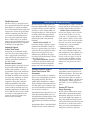
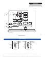
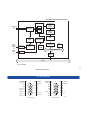
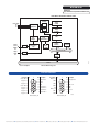
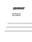
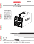
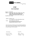
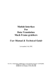
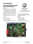
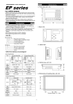
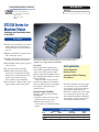
DT3130 Series
Compatible Windows Software
■
BUS: PCI
■
Type: Simultaneous Input Frame Grabber Boards
DT-Active Open Layers
32-Bit Frame Grabber SDK for
Windows 98/NT 4.0/2000/ME
■ DT-Acquire
■ DT Vision Foundry
■ GLI/2
DT3130 Series for
Machine Vision
Simultaneous Input Frame Grabber Boards
for the PCI Bus
Key Features
■ Contains the functionality of up to three
frame grabbers on one PCI short card,
enabling multiple image acquisition at a
low cost.
■ Handles monochrome, composite color,
M-5888
and S-video input sources.
■ Available option adds isolation from the
hazards of an industrial environment.
■ Programmable strobe outputs for precise
camera control.
■ 12 volt camera power connection.
■ PCI Bus Master and Scatter/Gather
architecture for intelligent image data
management; enables acquisition and
transfer to host memory at 30 fps
(RS-170/NTSC), 25 fps (CCIR/PAL).
■ Free DT-Acquire™ software enables you to
capture, display, and save image data.
The DT3131, DT3132, & DT3133 offer one, two, or three frame
grabbers on a single half-size PCI board.
Overview
Ideal Applications
Ideal for applications requiring simultaneous image acquisition from multiple
sources, low-cost DT3130 Series frame
grabbers contain the functionality of up to
three individual frame grabbers, all on one
half-size PCI board.
An option adds isolation from the
hazards of an industrial environment,
letting you add the features your application requires without paying for
unneeded extras.
Visual Inspection
Machine Vision
Automated Medical Imaging
Surveillance
• The DT3132 includes two active inputs
or six muxed, for up to six NTSC/PAL
color cameras, or two S-video and four
RS-170/CCIR, NTSC/PAL cameras.
• The DT3133 includes three active inputs
or nine muxed, for input of up to nine
RS-170/CCIR monochrome, NTSC/PAL
color cameras, or three S-video and six
RS-170/CCIR, NTSC/PAL cameras.
Extensive Input Flexibility
The DT3130 Series has three different
configurations:
• The DT3131 features one active input
and three muxed, for up to three
NTSC/PAL color cameras, or one
S-video and two 170/CCIR, NTSC/PAL,
cameras.
Features Summary
Camera Inputs
Board
DT3131
DT3132
DT3133
Active
1
2
3
Muxed
3
6
9
External
Trigger Inputs
1
2
3
Strobe
Outputs
1
2
3
Flexible Operation
The DT3130 Series is designed for complete operational flexibility. The on-board
frame grabbers are completely independent, with independent trigger inputs and
output strobes, and can be operated individually or simultaneously. This allows
you to tailor the board configuration to
meet your specific application requirements—whether they are for scientific
image analysis of individual images or for
multiple simultaneous image acquisition
for machine vision applications.
Industrial Options
to Meet Your Needs
Designed for use in industrial installations, the DT3130 Series frame grabbers
can be equipped with isolated trigger
inputs and isolated strobe outputs via an
isolation option (DT3131-ISO, DT3132ISO, DT3133-ISO).
Precise Camera Control
Each frame grabber on the DT3130 Series
boards includes flexible HSYNC and
VSYNC count capabilities, as well as a
programmable output strobe. Each frame
grabber’s strobe output can be based on
the HSYNC or VSYNC count, and can be
run in one-shot, continuous, or software
controlled strobe modes. The strobe
outputs have both polarity and pulsewidth programmability. This feature
allows for precise synchronization and
control of cameras and light sources for
demanding applications. In addition this
feature makes the DT3130 Series suitable
for a variety of other applications that
require the control of external events
based on video sync timing.
Real-Time Display, Non-Destructive Overlays
The DT3130 Series employs Microsoft’s
DirectDraw (DDI) standard, allowing you
to display real-time, live video with nondestructive overlays without adding costly display hardware (i.e. VGA circuitry) to
the frame grabber. This approach offers
many advantages over traditional frame
grabber display and overlay methods,
including:
Minimal CPU Bandwidth: The
DirectDraw display technique requires
minimal CPU bandwidth, leaving the
CPU free to perform image processing or
other tasks. Ideal for applications where
display video and processing occur
simultaneously, DDI allows for staggerfree images and smooth flowing, real-time
video with overlays.
Upgradable Compatibility: With DDI,
your DT3130 Series frame grabber will
work with any DirectDraw-compatible
graphics card. And since DirectDraw is
enabled through the graphics card driver,
you can upgrade an existing graphics card
to DDI by simply loading a new driver.
Flexible Graphics Card Selection:
Because the graphics card is not built
onto the frame grabber, you are not
“locked in” to the performance of the
frame grabber’s display circuitry. This
allows you to choose the frame grabber
that suits your needs and the graphics
card that meets your performance
requirements and budget.
Additional Features: Since DDI is the
same overlay technique used by video
game manufacturers, this capability gives
you the ability to have non-destructive
overlays of any size, shape, or color on
top of live video. In addition, overlays
can be translucent (semi clear), rotated,
animated, or even placed over scaled
images.
Extensive Software Support
Saves Time, Protects Your
Investment
which provides a common application
programming interface (API) across all
DT PCI frame grabbers. This means that
you can easily switch from one Data
Translation frame grabber to another, or
add more frame grabbers, with little or no
reprogramming. Adding support for a
new board is as easy as installing a new
driver.
Several software products are available to
help you get your application up and running quickly and easily. The Frame
Grabber SDK™ (included) is a complete
library of hardware-independent function
calls that enables you to control the operations of Data Translation’s PCI frame grabbers in Visual C or Visual C++.
Optionally, DT-Active Open Layers™ is an
ActiveX® control that enables you to use
Data Translation’s PCI frame grabbers with
graphical programming environments
such as Microsoft Visual Basic and Visual
C++.
Both packages adhere to Data Translation’s
DT-Open Layers® software architecture,
System CPU Free for
Image Processing
Because of their PCI Bus Master design
and intelligent Scatter/Gather memorymanagement architecture, the DT3130
Series boards handle large amounts of
image data quickly and effectively, and
with no CPU intervention. This leaves the
host CPU free to do other tasks such as
image processing, data manipulation, or
other processor-intensive operations.
DT3130 Series
BUS: PCI
Type: Simultaneous Input Frame Grabber Boards
A/D Stage
8-Bit Y
Video Inputs
0:2
Input
Multiplexer
8-Bit
CrCb
Trigger
Input
*
Isolation
Programmable
Image
Cropping
Clock
Synchronization
Sync
Stripper
Camera
Control
Output
Programmable
Image
Scaling
Acquire
Clock
28.6 MHz
Programmable
Clock Control
Logic
FIFO
PCI Bus
Interface
PMC
Connector
32
32
Secondary PCI Bus
*
Isolation
32
PCI to PCI
Bridge
32
PCI Bus
M-5897
*Used for ISO Option
DT3131 Block Diagram
3131 User Connections
Description Pin
6
N/C 8
15 12V Ground
N/C 7
N/C 6
11 14 +12V
1
13 N/C
Strobe Out + 5
12 N/C
N/C 4
N/C 3
Trigger in – 2
Trigger in + 1
Pin Description
11 N/C
5
15 10 Strobe Out –
9
10
Connector J1
N/C
Description Pin
Pin Description
6
N/C 8
15 Analog Ground
N/C 7
N/C 6
11 14 N/C
1
13 N/C
GND 5
12 N/C
C0 4
VID2 or Y0 3
VID1 2
VID0 1
11 N/C
5
15 10 Ground
9
N/C
10
Connector J2
M-5899
Data Translation, Inc. ■ US/Canada: (800) 525-8528, (508) 481-3700, ■ Email: [email protected], ■ UK: (44) (0) 1256 3333 30, ■ Germany: (49) 7142-9531-0, ■ Internet: www.datatranslation.com
Bold outlines indicate two identical circuits
A/D Stage
8-Bit Y
Video Inputs
0:2
3:5
Input
Multiplexer
8-Bit
CrCb
Isolation
FIFO
Acquire
Clock
28.6 MHz
Programmable
Clock Control
Logic
PCI Bus
Interface
PMC
Connector
32
32
Secondary PCI Bus
*
Isolation
32
PCI to PCI
Bridge
32
PCI Bus
*Used for ISO Option
M-5898
Trigger
Inputs
0:1
*
Programmable
Image
Cropping
Clock
Synchronization
Sync
Stripper
Camera
Control
Outputs
0:1
Programmable
Image
Scaling
DT3132 Block Diagram
3132 User Connections
Description Pin
6
Strobe Out 1+ 8
15 12V Ground
N/C 7
N/C 6
11 14 +12V
1
13 N/C
Strobe Out 0+ 5
12 N/C
Trigger in 1– 4
Trigger in 1+ 3
Trigger in 0– 2
Trigger in 0+ 1
Pin Description
11 N/C
5
15 10 Strobe Out –
9
10
Connector J1
Strobe Out 1–
Description Pin
Pin Description
6
VID5 or Y1 8
15 Analog Ground
VID4 7
VID3 6
11 14 N/C
1
13 N/C
GND 5
12 N/C
C0 4
VID2 or Y0 3
VID1 2
VID0 1
11 N/C
5
15 10 Ground
9
C1
10
Connector J2
M-5899
DT3130 Series
BUS: PCI
Type: Simultaneous Input Frame Grabber Boards
Bold outlines indicate three identical circuits
A/D Stage
Video Inputs
0:2
3:5
6:8
8-Bit Y
Input
Multiplexer
8-Bit
CrCb
Sync
Stripper
Camera
Control
Outputs
0:2
Trigger
Inputs
0:2
Programmable
Image
Scaling
*
Isolation
Programmable
Image
Cropping
FIFO
Clock
Synchronization
PCI Bus
Interface
Acquire
Clock
28.6 MHz
Programmable
Clock Control
Logic
PMC
Connector
32
32
Secondary PCI Bus
*
Isolation
32
PCI to PCI
Bridge
M-5902
32
PCI Bus
DT3133 Block Diagram
*Used for ISO Option
3133 User Connections
Description Pin
6
Strobe Out 1+ 8
15 12V Ground
Trigger in 2– 7
Trigger in 2+ 6
11 14 +12V
1
13 N/C
Strobe Out 0+ 5
12 Strobe Out 2–
Trigger in 1– 4
Trigger in 1+ 3
Trigger in 0– 2
Trigger in 0+ 1
Pin Description
11 Strobe Out 2+
5
15 10 Strobe Out 0–
9 Strobe Out 1–
10
Connector J1
Description Pin
Pin Description
6
VID5 or Y1 8
15 Analog Ground
VID4 7
VID3 6
11 14 C2
1
13 VID8 or Y2
GND 5
12 VID7
C0 4
VID2 or Y0 3
VID1 2
VID0 1
11 VID6
5
15 10 Ground
9
C1
10
Connector J2
M-5899
Data Translation, Inc. ■ US/Canada: (800) 525-8528, (508) 481-3700, ■ Email: [email protected], ■ UK: (44) (0) 1256 3333 30, ■ Germany: (49) 7142-9531-0, ■ Internet: www.datatranslation.com
DT3130 Series Specifications
Video Input
Video Format: Composite video and S-video
(Y/C) formats; RS-170, RS-330, and NTSC
(60 Hz) or CCIR and PAL (50 Hz); interlaced;
software selectable
Timing Format: Standard 60 Hz and 50 Hz
timing formats are supported;
software selectable
Inputs:
DT3131: 1 active input at any one time; 1
active composite out of 3 multiplexed composite, or 1 S-video and 2 composite; all
inputs ac coupled
DT3132: 2 simultaneously active inputs at
any one time; 2 active composite out of
6 multiplexed composite, or 2 S-video
and 4 composite; all inputs ac coupled
DT3133: 3 simultaneously active inputs at
any one time; 3 active composite out of
9 multiplexed composite, or 3 S-video
and 6 composite; all inputs ac coupled
Video Signal: 1 volt peak to peak, 75 ohms
Spatial Resolution: 640 x 480 (60 Hz);
768 x 576 (50 Hz)
Acquisition
Digitization: Twin 8-bit A/Ds, one for
monochrome, and one for chroma;
data derived to YCrCb format.
Pixel Jitter: ±6 nsec maximum
Aspect Ratio: 1:1 Square pixels,
depending on scaling factors
Frame Grab Speed: 1/30 s (60 Hz),
1/25 s (50 Hz)
Modes: Interlaced (start on next even,
next odd, or next field), single frame
or continuous operation; all software
selectable
active video input; individually controllable;
TTL levels; Programmable HSYNC and
VSYNC counts; Strobe output pulse-width
programmable from 3.3 to 427 msec with
selectable polarity
Control Signal Isolation:
Available via the ISO option.
Video Display
Uses PC’s graphics card and monitor for
display. Real-time video display and
non-destructive, real-time animated overlays
performed using DirectDraw (DDI)
Video Transfer Rate
55 MB/s typical, 132 MB/s max. Board
operates as a Bus Master using Burst Mode
for data transfer to host memory. Intelligent
Scatter/Gather architecture used for image
data management in host memory.
Power Requirements
+5 V @ 1 A typical
+12 V @ 1.5 A max (for camera power)
via CPU power supply harness
Physical and Environmental
Form: Half-size PCI bus board (short card)
Dimensions: 10.7 cm x 17.5 cm
(4.2 in. x 6.875 in.)
Weight: 150 g (5.3 ounces)
Operating Temperature: 0° to 50° C
(32° to 122° F)
Storage Temperature: –25° to 70° C
(–13° to 158° F)
Relative Humidity: Up to 90%, non-condensing
Warranty
One year limited parts and labor
ISO Option
On-Board Processing
Region Of Interest: Programmable
ROI window defines video data to be
transferred to memory; pixels outside
window are discarded
Scaling: Images scaleable to 4 pixels by 4 lines,
performed using linear phase interpolation;
software selectable
Data Formats
Image data can be output in 32, 24, 16,
and 15-bit RGB, 16-bit YUV, or 8-bit
monochrome formats
Control Signals
External trigger inputs: DT3131: 1 total;
DT3132: 2 total, DT3133: 3 total
TTL levels—one per active video input
Camera strobe outputs: DT3131: 1 total;
DT3132: 2 total, DT3133: 3 total—one per
System Requirements
Factory-installed option provides isolation
for all DT3130 Series control signal inputs
and outputs
Trigger Inputs
Number: 3 inputs
Isolation: optical isolation, ≥250 VDC
Logic High input voltage 3.5-32 VDC
Logic Low input voltage <1.0 VDC
Input resistance 3.3 k Ω typical
■ Pentium-class processor, 133 MHz or faster;
Pentium II recommended
■ At least one available PCI Bus slot
■ Microsoft Windows 98/2000/ME
■ Triton PCI chipset (or better) and supporting system BIOS
■ 16 MB of system RAM minimum for Windows 98;
32 MB minimum for Windows 2000/ME
■ CD-ROM drive (for software installation)
■ DDI-compatible graphics adapter
Ordering Summary
All Data Translation hardware products are covered by a 1-year warranty. For pricing information see a current price list, visit our web
site, or call your local reseller.
The DT3130 frame grabber is shipped with the Imaging
Omni CD, which includes device drivers for all DT PCI frame
grabbers, DT-Acquire image-capture software application,
example programs with source code, Frame Grabber SDK,
and product documentation in PDF format.
■ DT3131—Single frame grabber board, 3 inputs (muxed),
1 active (RS-170/NTSC, CCIR/PAL)
■ DT3132—Double frame grabber board, 6 inputs (muxed),
2 simultaneously active (RS-170/NTSC, CCIR/PAL)
■ DT3133—Triple frame grabber board, 9 inputs (muxed),
3 simultaneously active (RS-170/NTSC, CCIR/PAL)
■ DT3131-ISO*—DT3131 with isolation option
■ DT3132-ISO*—DT3132 with isolation option
■ DT3133-ISO*—DT3133 with isolation option
*This is not a user-installable option and must be factory installed
when ordered. Call for information on OEM and volume discounts.
Accessoriesnput/outpSeries
boards
■ EP311—6 m (2 ft.) 15-pin cable for video connection (up
to 3 cameras simultaneous)
■ EP312—1.0 m (3 ft.) 15-pin cable for
control signal connection (up to three triggers, three
strobes, and 12V power)
■ EP314—.6 m (2 ft.) cable for connection of up to 9 cameras multiplexed
■ EP317—2 m (6 ft.) cable forS-video connection
(1 camera)
■ DT3130 Series User’s Manual in hard-copy form
Software
All software packages include a copy of the software on
CD-ROM, a user’s manual, and 90 days of complimentary
telephone support.
■ DT Active Open Layers Active X Control
SP0974-CD
■ For other compatible software, consult the software
section of this handbook, or call for details.
Strobe Outputs
Number: 3 outputs
Isolation: optical isolation, ≥250 VDC
Maximum Load current 100 mA
Maximum load voltage 40 VDC
Overcurrent protection @300 mA
© Copyright 2002 Data Translation, Inc. All rights reserved.
All trademarks are the property of their respective holders.
Prices and specifications subject to change without notice.