1
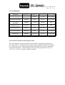
Report No.: EME-041156
Page 1 of 39
EMC
TEST REPORT
Report No.: EME-041156
Model No.: I-7005, I-7015, I-7019R, I-7045, I-7045D, I-7051, I-7051D,
I-7055, I-7055D, I-7530, I-87017R, I-87018R, I-87040,
I-87041, M-7017, M-7017-232, M-7017R, M-7018,
M-7018R, M-7019R, FR-2053, FR-2057, SG-3016, I-2541
Issued Date: Dec. 13, 2004
Applicant: ICP DAS Co., Ltd.
No. 111, Kuangfu N. Rd., Hukou Shiang, Hsinchu, Taiwan
Test By:
Intertek Testing Services Taiwan Ltd.
No. 11, Lane 275, Ko-Nan 1 Street, Chia-Tung Li,
Shiang-Shan District, Hsinchu City, Taiwan
This test report consists of 39 pages in total. It may be duplicated completely for
legal use with the allowance of the applicant. It shall not be reproduced except
in full, without the written approval of Intertek Laboratory. The test result(s) in
this report only applies to the tested sample(s).
Project Engineer
Reviewed By
Brandon Huang
Rico Deng
Report No.: EME-041156
Page 2 of 39
Table of Contents
1. General Information ..................................................................................................... 5
1.1 Identification of the EUT........................................................................................ 5
1.2 Additional information about the EUT................................................................... 5
1.3 Peripherals equipment ............................................................................................ 6
2. Test Summary ............................................................................................................... 7
3. Test Specifications ........................................................................................................ 8
3.1 Standards ................................................................................................................ 8
3.2 Mode of operation during the test........................................................................... 8
3.3 Performance criteria ............................................................................................... 9
3.4 Performance verification ........................................................................................ 9
4. EN 55022 Conducted Emission Test .......................................................................... 10
4.1 Mains Terminals Emission Test............................................................................ 10
4.1.1 Operating Environment ..................................................................................... 10
4.1.2 Test Procedure ................................................................................................... 10
4.1.3 Test Equipment ...................................................................................................11
4.1.4 Conducted Emission Limit .................................................................................11
4.1.5 Uncertainty of Conducted Emission...................................................................11
4.1.6 Mains Terminals Emission Data........................................................................ 12
5. EN 55022 Radiated Emission Test ............................................................................. 14
5.1 Operating Environment ........................................................................................ 14
5.2 Test Procedure ...................................................................................................... 14
5.3 Test Equipment ..................................................................................................... 15
5.4 Radiated Emission Limit ...................................................................................... 15
5.5 Uncertainty of Radiated Emission........................................................................ 15
5.6 Radiated Emission Test Data ................................................................................ 16
6. EN 61000-3-2 Harmonics........................................................................................... 18
6.1 Operating Environment ........................................................................................ 18
6.2 Test Procedure ...................................................................................................... 18
6.3 Test Equipment ..................................................................................................... 18
6.4 Test Result ............................................................................................................ 19
7. EN 61000-3-3 Voltage Fluctuations-Flicker............................................................... 20
7.1 Operating Environment ........................................................................................ 20
7.2 Test Procedure ...................................................................................................... 20
7.3 Test Equipment ..................................................................................................... 20
7.4 Test result.............................................................................................................. 21
Report No.: EME-041156
Page 3 of 39
8. IEC 61000-4-2 Electrostatic Discharge Immunity Test.............................................. 22
8.1 Operating Environment ........................................................................................ 22
8.2 Purpose ................................................................................................................. 22
8.3 Test Set-Up ........................................................................................................... 22
8.4 Test Conditions ..................................................................................................... 22
8.5 Test Equipment ..................................................................................................... 23
8.6 Test Result ............................................................................................................ 23
9. IEC 61000-4-3 Radiated, Radio-Frequency, Electromagnetic Field Immunity ......... 25
Test.............................................................................................................................. 25
9.1 Operating Environment ........................................................................................ 25
9.2 Purpose ................................................................................................................. 25
9.3 Test Set-Up ........................................................................................................... 25
9.4 Test Conditions ..................................................................................................... 25
9.5 Test Equipment ..................................................................................................... 26
9.6 Generation Of The Electromagnetic Field............................................................ 26
9.7 Test Results........................................................................................................... 27
10. IEC 61000-4-4 Electrical Fast Transient/Burst Immunity Test ................................ 28
10.1 Operating Environment ...................................................................................... 28
10.2 Purpose ............................................................................................................... 28
10.3 Test Set-Up ......................................................................................................... 28
10.4 Test Condition..................................................................................................... 28
10.5 Test Equipment ................................................................................................... 29
10.6 Test Results......................................................................................................... 29
11. IEC 61000-4-5 Surge Immunity Test ....................................................................... 30
11.1 Operating Environment ...................................................................................... 30
11.2 Purpose ............................................................................................................... 30
11.3 Test Set-Up ......................................................................................................... 30
11.4 Test Conditions ................................................................................................... 30
11.5 Test Equipment................................................................................................... 31
11.6 Test Results ......................................................................................................... 31
12. IEC 61000-4-6 Immunity To Conducted Disturbances, Inducted By ...................... 32
Radio-Frequency Fields.............................................................................................. 32
12.1 Operating Environment ...................................................................................... 32
12.2 Purpose ............................................................................................................... 32
12.3 Test Set-Up ......................................................................................................... 32
12.4 Test Conditions ................................................................................................... 32
12.5 Test Equipment ................................................................................................... 33
12.6 Generation And Calibration Of The Disturbance Signal.................................... 33
12.7 Test Results......................................................................................................... 34
Report No.: EME-041156
Page 4 of 39
13. IEC 61000-4-11 Voltage Dips, Short Interruptions And Voltage Variations ............ 35
Immunity Test............................................................................................................. 35
13.1 Operating Environment ...................................................................................... 35
13.2 Purpose ............................................................................................................... 35
13.3 Test Set-Up ......................................................................................................... 35
13.4 Test Condition..................................................................................................... 35
13.5 Test Equipment ................................................................................................... 35
13.6 Generation Of The Disturbance Signal .............................................................. 36
13.7 Test Result .......................................................................................................... 36
Appendix A1: External photo of EUT .......................................................................... 37
Appendix B1: Conducted Emission Test Set-up........................................................... 38
Appendix B2: Radiated Emission Test Set-up.............................................................. 39
Report No.: EME-041156
Page 5 of 39
1. General Information
1.1 Identification of the EUT
Product:
Model No.:
Applicant:
Rated Power:
Power Cord:
ICPDAS CPU with Converter
I-7005
ICP DAS Co., Ltd.
230Vac, 50Hz
3C×18AWG ×1.5meter with 2 cores
Data Cable:
Fiber cable 10meter × 1
Sample receiving date: Nov. 25, 2004
Testing date:
Nov. 26, 2004 ~ Dec.8, 2004
1.2 Additional information about the EUT
The EUT is an ICPDAS CPU with Converter, and was defined as information
technology equipment.
According to the hardware aspect, we verified the models listed as below are series
model to I-7005 (EUT), the difference please refer to the following table:
Model Number
Firmware
I-7005
8- channel Thermistor Input and 6-channel Alarm Output Module
I-7015
6-channel RTD Input Module
I-7019R
8-channel Universal Analog Input Module
I-7045
16-channel Isolated Digital Output Module
I-7045D
I-7045 with LED Display
I-7051
16-channel Isolated Digital Input Module
I-7051D
16-channel Isolated Digital Input Module
I-7055
8-channel Isolated Digital Input and 8-channel Isolated Digital Output Module
I-7055D
8-channel Isolated Digital Input and 8-channel Isolated Digital Output Module
I-7530
Intelligent RS-232 to CAN converter
I-87017R
8-channel Analog Input Module
Report No.: EME-041156
Page 6 of 39
Model Number
Firmware
I-87018R
8-channel Thermocouple Input Module
I-87040
32-channel Isolated Digital Input Module
I-87041
32-channel Isolated Digital Output Module
M-7017
8-channel Analog Input Module
M-7017-232
8-channel Analog Input Module
M-7017R
8-channel Analog Input Module with High Over Voltage Protection
M-7018
8-channel Thermocouple Input Module
M-7018R
8-channel Thermocouple Input Module with High Over Voltage Protection
M-7019R
8-channel Universal Input Module with High Over Voltage Protection
FR-2053
16-channel Isolated Digital Input Module
FR-2057
16-channel Isolated Digital Output Module
SG-3016
Isolated Strain Gauge Input Module
I-2541
RS-232/422/485 to Fiber Optic Converter
For more detail features, please refer to user's Manual.
1.3 Peripherals equipment
Peripherals
Notebook PC
Manufacturer
Dell
Fiber Optic Converter ICP DAS
Product No.
Serial No.
PP01L
CN-03P83-48643-33O-3930
I-2541
N/A
Report No.: EME-041156
Page 7 of 39
2. Test Summary
Emission
Test Type
Result
Standard
EN 55022: 1998
+A1: 2000+A2: 2003
Class B
EN 61000-3-2: 2000
Class A
EN 61000-3-3: 1995
+A1: 2001
Remarks
Conducted Test
PASS
Pass by –2.60 dB at 0.155 MHz
Neutral Phase
Radiated Test
PASS
Pass by –5.61 dB at 100.8 MHz
With antenna polarization vertical
PASS
Meet the requirements
PASS
Meet the requirements
Harmonic current
Emissions
Voltage fluctuation
& Flicker
Immunity (EN 55024: 1998+A1: 2001+A2: 2003)
Standard
Test Type
Result
Performance Criteria
IEC 61000-4-2:
1995+A1: 1998+ A2:
2000
ESD test
PASS
Criterion B
IEC 61000-4-3: 2002
RS test
PASS
Criterion A
IEC 61000-4-4: 2004
EFT test
PASS
Criterion B
IEC 61000-4-5: 2001
Surge test
PASS
Criterion B
IEC 61000-4-6: 2003
CS test
PASS
Criterion A
IEC 61000-4-11:
1994+A1: 2001
Dip test
PASS
1. >95% reductionPerformance Criterion B
2. 30% reductionPerformance Criterion C
3. >95% reductionPerformance Criterion C
Test Judgment
Meets the requirements of
Performance Criterion A
Meets the requirements of
Performance Criterion A
Meets the requirements of
Performance Criterion A
Meets the requirements of
Performance Criterion A
Meets the requirements of
Performance Criterion A
Meets the requirements of
Voltage Dips:
1. >95% reductionPerformance Criterion A
2. 30% reductionPerformance Criterion A
3. >95% reductionPerformance Criterion B
Remark:
The EUT has been tested/evaluated and pass the EN 55022 without modification.
Report No.: EME-041156
Page 8 of 39
3. Test Specifications
3.1 Standards
EN 55022: 1998+A1: 2000+A2: 2003 Electromagnetic compatibility - requirements
for radio disturbance characteristics of information technology equipment.
EN 61000-3-2: 2000 Electromagnetic compatibility ─ Part 3. Limits
Section 2. Limits for harmonic current emissions (equipment input current ≤ 16 A per
phase)
EN 61000-3-3: 1995+A1: 2001 Electromagnetic compatibility ─ Part 3. Limits
Section 3. Limitation of voltage fluctuations and flicker in low-voltage supply systems
for equipment with rated current ≤ 16 A
EN 55024: 1998+A1: 2001+A2: 2003 Information technology equipment -
Immunity characteristics Limits and methods of measurement.
3.2 Mode of operation during the test
The EUT was supplied with 230Vac, 50Hz
The EUT was tested in normal operating mode.
Magnetic field immunity test:
The equipment does not contain devices components susceptitable to magnetic fields,
therefore, the test waived can be ignored.
Report No.: EME-041156
Page 9 of 39
3.3 Performance criteria
The performance criteria are based on the general criteria in the standard and specified
by the manufacturer/derived from the product specification.
Criteria A:
The equipment shall continue to operate as intended. No performance or loss of
function is allowed below performance level specified by manufacturer.
Criteria B:
Loss of function is allowed, provided the function self-recoverable or restored by the
operation of the controls by the user in accordance with manufacturers instructions or
after the test the equipment shall continue to operate as intended. Degradation of
performance or loss of function is allowed after the application of the phenomena below
a performance level specified by the manufacturer. During the test, degradation of
performance is allowed. However, no change of actual operating state or stored data is
allowed.
Criteria C:
Temporary degradation or loss of function or performance that requires operator
Intervention or system reset.
3.4 Performance verification
The EUT has been monitored (or observed) based on manufacturer’s specification; the
performance fulfilled the requirements of standard.
Report No.: EME-041156
Page 10 of 39
4. EN 55022 Conducted Emission Test
4.1 Mains Terminals Emission Test
4.1.1 Operating Environment
Temperature:
23 ℃ (10-40℃)
Relative Humidity: 55 % (10-90%)
Atmospheric Pressure: 1023 hPa (860-1060hPa)
Test Voltage: 230Vac, 50Hz
4.1.2 Test Procedure
AC Power
AMN
EUT
Peripherals
EMI Receiver
The EUT along with its peripherals were placed on a 1.0m(W)×1.5m(L) and 0.8m
in height wooden table and the EUT was adjusted to maintain a 0.4meter space
from a vertical reference plane. The EUT was connected to power mains through a
Artificial Mains Network (AMN), which provided 50 ohm coupling impedance for
measuring instrument and the chassis ground was bounded to the horizontal ground
plane of shielded room.
The excess power cable between the EUT and the AMN was bundled. All connecting
cables of EUT and peripherals were moved to find the maximum emission
Report No.: EME-041156
Page 11 of 39
4.1.3 Test Equipment
Equipment
Brand
Model No. Intertek ID No. Next Cal. Date
EMI Receiver
Rohde & Schwarz
ESCS 30
EC318
06/18/2005
AMN
Rohde & Schwarz
EHS3-Z5
EC320
01/08/2005
AMN
Rohde & Schwarz
ESH3-Z5
EC344
01/14/2005
Shield Room
N/A
N/A
N/A
N/A
Note: The above equipments are within the valid calibration period.
4.1.4 Conducted Emission Limit
Freq.
(MHz)
Maximum RF Line Voltage
Class A (dBμV)
Class B (dBμV)
Q.P.
Avg.
Q.P.
Avg.
0.15~0.50
79
66
66~56
56~46
0.50~5.00
73
60
56
46
5.00~30.0
73
60
60
50
4.1.5 Uncertainty of Conducted Emission
Expanded uncertainty (k=2) of conducted emission measurement is ±2.6 dB.
Report No.: EME-041156
Page 12 of 39
4.1.6 Mains Terminals Emission Data
Phase:
Line
Model No.:
I-7005
Test Condition: Normal operating mode
Remark:
1. Corr. Factor (dB)= AMN Factor (dB) + Cable Loss (dB)
2. Margin (dB) = Level (dBuV) – Limit (dBuV)
Report No.: EME-041156
Page 13 of 39
Phase:
Neutral
Model No.:
I-7005
Test Condition: Normal operating mode
Remark:
1. Corr. Factor (dB)= AMN Factor (dB) + Cable Loss (dB)
2. Margin (dB) = Level (dBuV) – Limit (dBuV)
Report No.: EME-041156
Page 14 of 39
5. EN 55022 Radiated Emission Test
5.1 Operating Environment
28 ℃
(10-40℃)
Atmospheric Pressure: 1023 hPa (860-1060hPa)
Relative Humidity: 40 %
(10-90%)
Test Voltage: 230Vac, 50Hz
Temperature:
5.2 Test Procedure
Antenna
Tower
1.0~4.0 m
10 m
Receiver
Antenna
EUT
0.8 m
Ground Plane
□
Peripherals
RF Test
Receiver
Radiated testing was performed at a 10 meters open area test site. The equipment under
test were placed on a turntable top 0.8 m above ground. The table was 360 degrees to
determine the position of the highest radiation. EUT is set 10 meters from the EMI
receiving antenna, which is mounted on a variable height mast. The antenna height is
varied between one meter and four meters above ground to find the maximum value
of the field strength. Both horizontal polarization and vertical polarization of the
antenna was set to conduct the measurement.
The bandwidth was set on the EMI meter 120 kHz.
The levels are quasi peak value readings. The frequency spectrum from 30 MHz to 1000
MHz was investigated.
Report No.: EME-041156
Page 15 of 39
5.3 Test Equipment
Equipment
Brand
Model No.
Intertek ID No. Next Cat. Date
EMI Receiver
Rohde & Schwarz
ESCS 30
EC318
06/18/2005
EMI Spectrum
Rohde & Schwarz
ESMI
EC317
07/14/2005
Turn Table
Electro-Metrics
EM4710
EP306
06/06/2005
Bilog Antenna
Schaffner
CBL611213
EC367
02/06/2005
Antenna Tower
Electro-Metrics
EM-4720
EP307
06/06/2005
Ferrite Clamp
Rohde & Schwarz
EZ-24
N/A
N/A
Note: The above equipments are within the valid calibration period.
5.4 Radiated Emission Limit
Class A(dBμV/m) Class B(dBμV/m)
Frequency (MHz)
Distance(m)
30~230
10
40
30
230~1000
10
47
37
Note:
1. The tighter limit shall apply at the edge between two frequency bands.
2. Distance refers to the distance in meters between the measuring instrument
Antenna and the closest point of EUT .
5.5 Uncertainty of Radiated Emission
Expanded uncertainty (k=2) of radiated emission measurement is ±3.58 dB.
Report No.: EME-041156
Page 16 of 39
5.6 Radiated Emission Test Data
Polarity:
Model No.:
Test Condition:
Vertical
I-7005
Normal operating mode
Remark:
1. Level (dBμV/m)= Factor (dB/m)+ Read Level (dBμV)
2. Factor = Antenna Factor (dB/m) + Cable Loss (dB)
3. Over Limit (Margin) (dB) = Level (dBμV/m) – Limit Line(dBμV/m)
Report No.: EME-041156
Page 17 of 39
Polarity:
Model No.:
Test Condition:
Horizontal
I-7005
Normal operating mode
Remark:
1. Level (dBμV/m)= Factor (dB/m)+ Read Level (dBμV)
2. Factor = Antenna Factor (dB/m) + Cable Loss (dB)
3. Over Limit (Margin) (dB) = Level (dBμV/m) – Limit Line(dBμV/m)
Report No.: EME-041156
Page 18 of 39
6. EN 61000-3-2 Harmonics
6.1 Operating Environment
Temperature:
25
℃
Atmospheric Pressure: 1023
Relative Humidity:
56
%
Test Voltage:
hPa
230Vac, 50Hz
6.2 Test Procedure
Harmonics of the fundamental current were measured up to 2 kHz using a digital power
analyzer. The test voltage was supplied from an AC source, which meets the
requirements according to the standard.
The steady-state harmonic current measurements were carried out using averaging.
The transitory harmonics were measured during an observation period of 2.5 minutes.
The disturbance duration time (limit 15 s) is defined as the total time under which the
transitory harmonics exceeds the limit level for steady-state harmonics during an
observation period of 2.5 minutes.
6.3 Test Equipment
Equipment
Brand
Model No.
Intertek ID No. Next Cal. Date
EMC Emission
EMC Partner HARMONICS-1000
EC364
Tester
Note: The above equipments are within the valid calibration period.
10/07/2005
Report No.: EME-041156
Page 19 of 39
6.4 Test Result
EUT:
I-7005
CLASSIFICATION:
SUMMARY RESULT:
CLASS A
PASS
Harmonic Current Results
Hn
AMPs
Current
Limit
Result
Hn
AMPs
Current
Limit
Result
1
0.130
NaN
Pass
21
0.001
0.107
Pass
2
0.008
1.080
Pass
22
0.001
0.084
Pass
3
0.023
2.300
Pass
23
0.001
0.098
Pass
4
0.003
0.430
Pass
24
0.000
0.077
Pass
5
0.015
1.140
Pass
25
0.001
0.090
Pass
6
0.003
0.300
Pass
26
0.000
0.071
Pass
7
0.004
0.770
Pass
27
0.001
0.083
Pass
8
0.002
0.230
Pass
28
0.000
0.066
Pass
9
0.002
0.400
Pass
29
0.001
0.078
Pass
10
0.0001
0.184
Pass
30
0.000
0.061
Pass
11
0.002
0.330
Pass
31
0.001
0.073
Pass
12
0.001
0.153
Pass
32
0.000
0.058
Pass
13
0.002
0.210
Pass
33
0.001
0.068
Pass
14
0.001
0.131
Pass
34
0.000
0.054
Pass
15
0.002
0.150
Pass
35
0.000
0.064
Pass
16
0.001
0.115
Pass
36
0.000
0.051
Pass
17
0.001
0.132
Pass
37
0.000
0.061
Pass
18
0.001
0.102
Pass
38
0.000
0.048
Pass
19
0.001
0.118
Pass
39
0.001
0.058
Pass
20
0.001
0.092
Pass
40
0.000
0.046
Pass
Report No.: EME-041156
Page 20 of 39
7. EN 61000-3-3 Voltage Fluctuations-Flicker
7.1 Operating Environment
Temperature:
25
℃
Atmospheric Pressure: 1023
Relative Humidity:
56
%
Test Voltage:
hPa
230Vac, 50Hz
7.2 Test Procedure
The voltage changes at the supply terminals were measured using the voltage method.
The test voltage was supplied from an AC source which meets the requirements
according to the standard. The voltage source has virtually zero internal impedance
and is connected
(1 phase)
Z = 0.4 + j 0.25Ω (total impedance)
(3 phases)
Impedance in line conductor: Za = 0.25 + j 0.25 Ω
Impedance in neutral conductor: Zn = 0.15 +j 0.10 Ω
The short-term flicker Pst is measured during a time interval of 10 minutes.
The long-term flicker Plt is evaluated from 12 subsequently measured short-term flicker
values.
7.3 Test Equipment
Equipment
Brand
Model No.
Intertek ID No. Next Cal. Date
EMC Emission
EMC Partner HARMONICS-1000
EC364
Tester
Note: The above equipments are within the valid calibration period.
10/07/2005
Report No.: EME-041156
Page 21 of 39
7.4 Test result
EUT:
I-7005
SUMMARY RESULT:
PASS
TEST CONDITIONS:
STANDARD TEST CONDITIONS
Pst max
Plt max
dc %
dmax %
d(t) Sec.
EUT DATA
0.010
0.010
LIMIT
1.00
0.65
RESULT
PASS
PASS
0.15
0.30
0.00
3.30
4.00
0.50
PASS
PASS
PASS
TEST ENABLED
⌧
Report No.: EME-041156
Page 22 of 39
8. IEC 61000-4-2 Electrostatic Discharge Immunity Test
8.1 Operating Environment
20 ℃ (15-35℃)
Temperature:
Relative Humidity: 48 % (30-60%)
Atmospheric Pressure: 1023 hPa
Test Voltage:
230Vac, 50Hz
8.2 Purpose
The object of the test is to evaluate the ESD immunity performance of EUT.
8.3 Test Set-Up
A horizontal coupling plane (HCP) was placed on a non-metallic table 0.8 m above a
reference ground plane (RGP) and connected to it with a cable with two 470 kΩ
resistors. The EUT was placed on an insulation sheet on the HCP and was operated
according to the specified operating mode.
A vertical coupling plane (VCP) was connected to the RGP with a cable with two 470 k
Ω resistors.
8.4 Test Conditions
Test level:
Air discharge
Contact discharge
-------------
+/- 8kV
+/- 4kV
Single discharge at 1 second interval positive discharge and negative discharge
The selected test points are listed in this table, the numbers refer to the figures attached.
Report No.: EME-041156
Page 23 of 39
8.5 Test Equipment
Equipment
Manufacturer
Electrostatic Discharge
System
NoiseKen
Model No. Intertek ID No. Next Cal. Date
ESS-2002
EC362
06/17/2005
Note: The above equipments are within the valid calibration period.
8.6 Test Result
Applied
Voltage
(kV)
Total No. of
Discharge
(Each Point)
Result
Criteria
Level
Remark
±2
25
P
A
-
±4
25
P
A
-
±2
20
P
A
-
±4
20
P
A
-
±8
20
P
A
-
HCP
( 4 sides)
±2
25
P
A
-
±4
25
P
A
-
VCP
( 4 sides)
±2
25
P
A
-
±4
25
P
A
-
Point of Discharge
(Contact) Point 6-14
Refer to figure attached 1
(Air) Point 1-5
Refer to figure attached 1
Note: 1. “P” means the EUT pass the test.
Note: 2. “-“ means not applicable
⌧
Meet criterion A – operated as intended during and after the test
□
Meet criterion B – operated as intended after the test
□
Meet criterion C – loss/ error of function
Report No.: EME-041156
Page 24 of 39
Figure 1: ESD Discharge Points
Report No.: EME-041156
Page 25 of 39
9. IEC 61000-4-3 Radiated, Radio-Frequency, Electromagnetic Field Immunity
Test
9.1 Operating Environment
Temperature:
20
℃
Atmospheric Pressure: 1023
Relative Humidity:
48
%
Test Voltage:
hPa
230Vac, 50Hz
9.2 Purpose
This test method subjects the EUT to a power source of disturbance comprising electric
and magnetic field, simulating those coming from intentional RF transmitters.
9.3 Test Set-Up
The EUT was placed on a non-metallic table 0.8 m above the reference ground plane
(RGP) and was operated according to its specified operating mode.
Ferrite tiles/absorbers were placed on the RGP between the EUT and the antenna to
reduce the reflections from the RGP. The EUT and its cables were exposed for the
electromagnetic field for 1.5m vertically and 1.5m horizontally.
The distance between antenna and EUT is 3 meter.
9.4 Test Conditions
1
Test field strength
V/m
1
1 kHz 80% AM
2
3
1 kHz 80% AM
3
10
1 kHz 80% AM
X
Special
1 kHz 80% AM
Test level
The frequency steps
Dwell time
Frequency range
Test ports
Test field strength
: 1﹪, Log sweep
: 3 sec
: 80MHz~1GHz
: Enclosure port
: 3V/m
Modulation
Report No.: EME-041156
Page 26 of 39
9.5 Test Equipment
Equipment
An-echoic chamber
7m×3m×3m
RF signal Generator
Manufacture
Model No.
Comtest
9708093
Instrumentation
Intertek ID No. Next Cal. Date
EC328
06/17/2005
Marconi
2024
EC301
07/11/2005
Kalmus
757LCB
EP314
N/A
MILMEGA
AS0102-30
EP318
N/A
Bi-log Antenna
EMCO
3141
EC304
12/17/2005
RF Power Meter
Boonton
4230
EC302
07/14/2005
Field Probe
Holaday
HI-4422
EC307
07/08/2005
Dual Band RF Power
Amplifier
High Power Microwave
Amplifier Series
Note: The above equipments are within the valid calibration period.
9.6 Generation Of The Electromagnetic Field
The electromagnetic field is generated from a computer controlled signal generator.
The output power is amplified and then radiated from broadband log periodic antennas.
For each sweep a pre-recorded empty chamber calibration file is used to establish the
required field strength. When using these files the field strength inside an area of
1.5/1.0 m x 1.5m is in accordance with the standard.
Report No.: EME-041156
Page 27 of 39
9.7 Test Results
Exposed Side: ⌧ Front
H: Horizontal
⌧ Left
⌧ Rear ⌧ Right
V: Vertical
Frequency
(MHz)
Horizontal/
Vertical
Result
Criteria
Level
Remark
80MHz to 1GHz
H
P
A
-
80MHz to 1GHz
V
P
A
-
Note: 1. “P” means the EUT pass the test.
Note: 2. “-“ means not applicable
⌧
Meet criterion A – operated as intended during and after the test
□
Meet criterion B – operated as intended after the test
□
Meet criterion C – loss/error of function
Report No.: EME-041156
Page 28 of 39
10. IEC 61000-4-4 Electrical Fast Transient/Burst Immunity Test
10.1 Operating Environment
Temperature:
20 ℃ (15-35℃)
Relative Humidity: 50 % (25-75%)
Atmospheric Pressure: 1023 hPa
Test Voltage:
230Vac, 50Hz
10.2 Purpose
The purpose of this test is to evaluate the EUT performance during the repetitive
transient bursts applied to power port and ports for I/O ports.
For power port testing, the EUT was placed on a non-metallic table 0.8 m above a
reference ground plane (RGP) and was put into operation according to the specified
operating mode.
10.3 Test Set-Up
For I/O ports testing, the EUT was placed on a non-metallic support 0.1 m above a
reference ground plane (RGP) and operated in the operating mode specified.
10.4 Test Condition
Open-circuit output test voltage (±10%) and repetition rate of the impulses (±20%)
On I/O (Input/Output) signal,
On power supply port, PE
Data and control ports
Level
Voltage peak Repetition rate Voltage peak Repetition rate
KV
kHz
KV
kHz
1
0.5
5 or 100
0.25
5 or 100
2
1
5 or 100
0.5
5 or 100
3
2
5 or 100
1
5 or 100
4
4
5 or 100
2
5 or 100
(1)
X
Special
Special
Special
Special
NOTE 1 Use of 5 kHz repetition rates is traditional; however, 100 kHz is closer to reality. Product
committees should determine which frequencies are relevant for specific products or product types.
NOTE 2 With some products, there may be no clear distinction between power ports and I/O ports, in
which case it is up to product committees to make this determination for test purposes.
(1) “x” is an open level. The level has to be specified in the dedicated equipment
specification
Report No.: EME-041156
Page 29 of 39
10.5 Test Equipment
Equipment
Manufacture
Model No.
EFT/Burst Tester
Keytek
CE40
Intertek ID No. Next Cal. Date
EC312
07/25/2005
Note: The above equipments are within the valid calibration period.
10.6 Test Results
Power supply line and Signal Line &
Protective earth terminal Control Line
Criteria
Level
Level
Polarity
0.25kV
+
-
-
-
0.25kV
-
-
-
-
0.5kV
+
-
P
A
0.5kV
-
-
P
A
1kV
+
P
-
A
1kV
-
P
-
A
2kV
+
-
-
-
2kV
-
-
-
-
4kV
+
-
-
-
4kV
-
-
-
-
Note: 1. “P” means the EUT pass the test.
Note: 2. “-“ means not applicable
⌧
Meet criterion A - operated as intended during and after the test
□
Meet criterion B - operated as intended after the test
□
Meet criterion C - loss/error of function
Report No.: EME-041156
Page 30 of 39
11. IEC 61000-4-5 Surge Immunity Test
11.1 Operating Environment
20 ℃ (15-35℃)
Temperature:
Atmospheric Pressure: 1023 hPa
Relative Humidity: 50 % (10-75%)
Test Voltage:
230Vac, 50Hz
11.2 Purpose
The object of this test is to establish a common reference to evaluate the performance of
EUT when subjected to high-energy disturbances on the power and interconnection
lines.
11.3 Test Set-Up
The EUT was placed on a non-metallic support 0.8 m above a reference ground plane
and was put into operation according to the specified operating mode.
11.4 Test Conditions
For power supply line
Level
Open circuit test voltage
kV +/- 10%
Remark
1
0.5
L1 to L2
2
1.0
3
2.0
4
4.0
L1 to L2
L1 to Gnd
L2 to Gnd
-
X
Special
-
Note: “X” is an open class. This level can be specified in the product specification
Surge wave form: 1.2 x 50 µs, Repetition rate: 1 /min (max)
Report No.: EME-041156
Page 31 of 39
11.5 Test Equipment.
Equipment
Manufacture
Model No.
Surge Tester
Key Tek
EMC Pro
Intertek ID No. Next Cal. Date
EC313
09/24/2005
Note: The above equipments are within the valid calibration period.
11.6 Test Results
Test 5 times for each voltage
Phase
Volt
Mode
L
0.5kV
N
L
1kV
N
L
G
1kV/2kV
N
G
Polarity
+
+
+
+
-
0
45
90
P
P
P
P
P
P
P
P
-
P
P
P
P
P
P
P
P
135 180 215 270 315
-
P
P
P
P
P
P
P
P
-
P
P
P
P
P
P
P
P
Note: 1. “P” means the EUT pass the test.
Note: 2. “-“ means not applicable
⌧
Meet criterion A - operated as intended during and after the test
□
Meet criterion B - operated as intended after the test
□
Meet criterion C - loss/error of function
-
Criteria
level
A
A
A
A
A
A
A
A
Report No.: EME-041156
Page 32 of 39
12. IEC 61000-4-6 Immunity To Conducted Disturbances, Inducted By
Radio-Frequency Fields
12.1 Operating Environment
Temperature:
20
°C
Atmospheric Pressure: 1023
Relative Humidity:
50
%
Test Voltage:
hPa
230Vac, 50Hz
12.2 Purpose
The test method subjects the EUT to a power source of disturbance comprising electric
and magnetic field, simulating those coming from intentional RF transmitters.
The measurement is for evaluating the performance of EUT when subjected to RF
conducted disturbance.
12.3 Test Set-Up
The EUT was placed on a non-metallic support 0.1 m above a reference ground plane
(RGP) with the coupling/decoupling network (CDN) placed 0.3 m from the EUT on the
RGP. The injection clamp was placed 0.3 m from the EUT on the RGP.
12.4 Test Conditions
1
Voltage
(Vrms)
1
1 kHz 80% AM
2
3
1 kHz 80% AM
3
10
1 kHz 80% AM
X
Special
1 kHz 80% AM
Test level
The frequency steps
Dwell time
Frequency range
Test ports
Test voltage
: 1﹪, Log sweep
: 3 sec
: 150kHz to 80MHz
: AC port, Signal port
: 3Vrms
Modulation
Report No.: EME-041156
Page 33 of 39
12.5 Test Equipment
Equipment
Manufacture
Model No.
RF signal Generator
Dual Band RF Power
Amplifier
Marconi
2024
EC301
07/11/2005
Kalmus
757LCB
EP314
N/A
4412-016
EC305
01/05/2005
4413-016
EC306
01/05/2005
4230
EC302
07/14/2005
RF Injection Clamp
Luthi
EM101
EC308
Coupling And
Schaffner
CDN T400
EC385
Decoupling Network
Note: The above equipments are within the valid calibration period.
01/05/2005
Coupling network
Coupling network
RF Power Meter
Comtest
instrument
Comtest
instrument
Boonton
Intertek ID No. Next Cal. Date
04/01/2005
12.6 Generation And Calibration Of The Disturbance Signal
The disturbance signal is generated from a computer controlled signal generator.
The output signal is amplified and injected to the CDN/injection clamp. The disturbance
signal level was calibrated as specified in the standard. A power meter was connected
to the EUT side of the CDN through a 150 -50Ω adapter. The auxiliary equipment
(AE) side of the network was terminated with 150Ω to ground during the calibration.
The generator settings obtained during the calibration procedure were later repeated in
the tests.
Report No.: EME-041156
Page 34 of 39
12.7 Test Results
Frequency
(MHz)
Test Port/Line
Result
Criteria
Level
Remark
0.15MHz to 80MHz
Power Line
P
A
-
0.15MHz to 80MHz
Signal Line
P
A
-
Note: 1. “P” means the EUT pass the test.
Note: 2. “-“ means not applicable
⌧
Meet criterion A – operated as intended during and after the test
□
Meet criterion B – operated as intended after the test
□
Meet criterion C – loss╱error of function
Report No.: EME-041156
Page 35 of 39
13. IEC 61000-4-11 Voltage Dips, Short Interruptions And Voltage Variations
Immunity Test
13.1 Operating Environment
20 ℃ (15-35℃)
Temperature:
Relative Humidity: 50 % (25-75%)
Atmospheric Pressure: 1023 hPa
Test Voltage:
230Vac, 50Hz
13.2 Purpose
The object of this standard is to establish a common reference for evaluating the
immunity of electrical and electronic equipment when subjected to voltage dips, short
interruptions, and voltage variations.
13.3 Test Set-Up
The EUT was placed on a non-metallic support 0.8 m above a reference ground plane
and was put into operation according to the specified operating mode.
13.4 Test Condition
Reduction
'% of rated
Test
Level % UT
Duration
(Period)
Tests
Recovery
Time
>95% Dip
0% Short Circuit
0.5
3
10 Sec.
>95% Dip
0% Open Circuit
0.5
3
10 Sec.
30% Dip
70%
25
3
10 Sec.
Test
Level % UT
Duration
(Period)
Tests
Recovery Time
0% Short Circuit
250
3
10 Sec.
0% Open Circuit
250
3
10 Sec.
13.5 Test Equipment
Equipment
Manufacturer
Model No.
Dip Tester
Keytek
EMC Pro
Intertek ID No. Next Cal. Date
EC313
Note: The above equipments are within the valid calibration period.
09/24/2005
Report No.: EME-041156
Page 36 of 39
13.6 Generation Of The Disturbance Signal
The disturbance signal is generated using a programmable AC power source with
pre-programmed test sequences for each test.
13.7 Test Result
I. Dip of mains voltage
Test
Level
1
2
Reduction
'% of rated
Test
Level % UT
>95% Dip
0% Short Circuit
0.5
3
10 Sec.
A
>95% Dip
0% Open Circuit
0.5
3
10 Sec.
A
30% Dip
70%
25
3
10 Sec.
A
Duration
Recovery Criteria
Tests
(Period)
Time
Level
II. 0﹪of mains voltage
Test
Item
Test
Level % UT
Duration
(Period)
Tests
Recovery
Time
Criteria
Level
1
0% Short Circuit
250
3
10 Sec.
B
2
0% Open Circuit
250
3
10 Sec.
B
□ Meet criterion A – operated as intended during and after the test
⌧ Meet criterion B – operated as intended after the test
□ Meet criterion C – loss╱error of function
Report No.: EME-041156
Page 37 of 39
Appendix A1: External photo of EUT
Report No.: EME-041156
Page 38 of 39
Appendix B1: Conducted Emission Test Set-up
Report No.: EME-041156
Page 39 of 39
Appendix B2: Radiated Emission Test Set-up