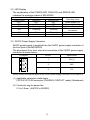
1
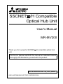
SSCNET /H Compatible Optical Hub Unit User's Manual MR-MV200 Thank you for buying the SSCNET /H compatible optical hub unit. Prior to use, please read both this manual and detailed manual thoroughly and familiarize yourself with the product. BCN-B62008-347-A(1407)MEE ©2014 MITSUBISHI ELECTRIC CORPORATION SAFETY PRECAUTIONS (Please read these instructions before using this equipment.) Before using this product, please read this manual and the relevant manuals introduced in this manual carefully and pay full attention to safety to handle the product correctly. Refer to the User's manual of the CPU module to use for a description of the PLC system safety precautions. In this manual, the safety instructions are ranked as "DANGER" and "CAUTION". DANGER CAUTION Indicates that incorrect handling may cause hazardous conditions, resulting in death or severe injury. Indicates that incorrect handling may cause hazardous conditions, resulting in medium or slight personal injury or physical damage. Depending on circumstances, procedures indicated by CAUTION may also be linked to serious results. In any case, it is important to follow the directions for usage. Please save this manual to make it accessible when required and always forward it to the end user. A-1 [Design Precautions] DANGER Configure safety circuits external to the controller to ensure that the entire system operates safely even when a fault occurs in the external power supply or the controller. Failure to do so may result in an accident due to an incorrect output or malfunction. (1) Configure external safety circuits, such as an emergency stop circuit, protection circuit, and protective interlock circuit for forward/reverse operation or upper/lower limit positioning. (2) When the controller detects an error such as a watchdog timer error by the selfdiagnostic function, all outputs are turned off. Also, output controls may not work when an error occurs in the part, such as I/O control part, where the controller cannot detect any error. To ensure safety operation in such a case, provide a safety mechanism or external circuit. (3) Outputs may remain on or off due to a failure of an output module relay, transistor, or triac. To ensure safety operation, configure an external circuit for monitoring output signals that could cause a serious accident. ● Noise interference can cause erroneous data to be written to the controller, resulting in an incorrect operation of the controller which may cause an accident, or damage the machine. Always ensure the following items are observed. (1) Do not bundle main circuit lines or high-voltage lines with load lines. Do not keep these lines close to each other as they are easily affected by noise and surge induction. When wiring, keep the above lines at least 100mm (3.94inch) apart. (2) The shield of shielded cords and shielded cables must be grounded to a point on the PLC side. However, do not use a common ground with strong electrical equipment. (3) Input, power supply, and optical fiber connectors should be used without any forced applied on them. Excessive force will cause cables to disconnect and fail. ● Provide appropriate circuits external to the Motion controller to prevent cases where danger may result from abnormal operation of the overall system in the event of an external power supply fault or Motion controller failure. ● Mount the Motion controller, servo amplifier, servomotor and regenerative resistor on incombustible. Mounting them directly or close to combustibles will lead to fire. ● If a fault occurs in the Motion controller or servo amplifier, shut the power OFF at the servo amplifier’s power source. If a large current continues to flow, fire may occur. ● When using a regenerative resistor, shut the power OFF with an error signal. The regenerative resistor may abnormally overheat due to a fault in the regenerative transistor, etc., and may lead to fire. ● Always take heat measures such as flame proofing for the inside of the control panel where the servo amplifier or regenerative resistor is mounted and for the wires used. Failing to do so may lead to fire. ● Do not apply a voltage other than that specified in the instruction manual on any terminal. Doing so may lead to destruction or damage. ● Do not mistake the polarity ( + / - ), as this may lead to destruction or damage. ● A-2 [Installation Precautions] CAUTION Never try to disassemble or modify module. It may cause product failure, operation failure, injury or fire. For repairs, please contact the Mitsubishi representative in your region. ● Do not drop or apply strong impact on this product. Doing so will damage the product. ● Use the controller in an environment that meets the general specifications contained in this manual. Using this Motion controller in an environment outside the range of the general specifications could result in electric shock, fire, operation failure, and damage to or deterioration of the product. ● When using the Motion controller in the environment of much vibration, tighten the module with a screw. Tighten the screw in the specified torque range. Under tightening may cause a drop, short circuit or operation failure. Over tightening may cause a drop, short circuit or operation failure due to damage to the screw or module. ● Completely turn off the externally supplied power used in the system before installation or removing the module. Not doing so could result in electric shock or damage to the product. ● Do not directly touch the module's conductive parts and electronic components. Doing so may cause an operation failure or give damage to the module. ● Lock the control panel and prevent access to those who are not certified to handle or install electric equipment. ● [Wiring Precautions] DANGER Completely turn off the externally supplied power used in the system before installation or placing wiring. Not doing so could result in electric shock or damage to the product. ● When turning on the power supply or operating the module after wiring, be sure that the module's terminal covers are correctly attached. Not attaching the terminal cover could result in electric shock. ● CAUTION Be sure to ground of the earth terminal FG and LG. Not doing so could result in electric shock or operation failure. (Ground resistance: 100 or less) ● When wiring in the module, be sure that it is done correctly by checking the product's rated voltage and the terminal layout. Connecting a power supply that is different from the rating or incorrectly wiring the product could result in fire or damage. ● External connections shall be crimped or pressure welded with the specified tools, or correctly soldered. Imperfect connections could result in short circuit, fire, or operation failure. ● Tighten the terminal screws within the specified torque range. If the terminal screws are loose, it could result in short circuit, fire, or operation failure. Tightening the terminal screws too far may cause damages to the screws and/or the module, resulting in drop, short circuit, or operation failure. ● A-3 CAUTION ● Be sure there are no foreign matters such as sawdust or wiring debris inside the module. Such debris could cause fire, damage, or operation failure. [Startup and Maintenance Precautions] DANGER Do not touch the terminals while power is on. Doing so could cause electric shock. ● Switch off all phases of the externally supplied power used in the system when cleaning the module or retightening the terminal or module mounting screws. Not doing so could result in electric shock. Under tightening of terminal screws can cause a short circuit or malfunction. Over tightening of screws can cause damages to the screws and/or the module, resulting in fallout, short circuits, or malfunction. ● The capacitor is mounted to the modules. Do not incinerate the modules so that the incineration of capacitor may cause burst. For disposal of the modules, request for specialized industrial waste disposal services who has incineration facility. ● CAUTION Never try to disassemble or modify module. It may cause product failure, operation failure, injury or fire. ● Use any radio communication device such as a cellular phone or a PHS phone more than 25cm (9.84inch) away in all directions of the controller. Failure to do so may cause a malfunction. ● Completely turn off the externally supplied power used in the system before installation or removing the module. Not doing so could result in electric shock, damage to the module or operation failure. ● Before touching the module, always touch grounded metal, etc. to discharge static electricity from human body. Failure to do so may cause the module to fail or malfunction. ● Do not directly touch the module's conductive parts and electronic components. Touching them could cause an operation failure or damage the module. ● A-4 [Disposal Precautions] When you discard Motion controller, servo amplifier, a battery (primary battery) and other option articles, please follow the law of each country (area). CAUTION This product is not designed or manufactured to be used in equipment or systems in situations that can affect or endanger human life. ● When considering this product for operation in special applications such as machinery or systems used in passenger transportation, medical, aerospace, atomic power, electric power, or submarine repeating applications, please contact your nearest Mitsubishi sales representative. ● Although this product was manufactured under conditions of strict quality control, you are strongly advised to install safety devices to forestall serious accidents when it is used in facilities where a breakdown in the product is likely to cause a serious accident. ● [Transportation Precautions] CAUTION ● When not using the module for a long time, disconnect the power line from the Motion controller or servo amplifier. ● Place the Motion controller and servo amplifier in static electricity preventing vinyl bags and store. ● When storing for a long time, please contact with our sales representative. Also, execute a trial operation. ● When fumigants that contain halogen materials such as fluorine, chlorine, bromine, and iodine are used for disinfecting and protecting wooden packaging from insects, they cause malfunction when entering our products. Please take necessary precautions to ensure that remaining materials from fumigant do not enter our products, or treat packaging with methods other than fumigation (heat method). Additionally, disinfect and protect wood from insects before packing products. A-5 PRÉCAUTIONS DE SÉCURITÉ (Lire ces précautions avant toute utilisation du produit.) Avant d'utiliser ce produit, prière de lire attentivement ce manuel ainsi que les manuels auxquels il renvoie, et toujours considérer la sécurité comme de la plus haute importance en manipulant le produit correctement. Se reporter au Manuel de l'utilisateur du module UC à utiliser pour une présentation détaillée des précautions de sécurité concernant le système de l'automate programmable. Dans ce manuel, les précautions de sécurité sont classées en deux niveaux, à savoir : "DANGER" et " ATTENTION". DANGER ATTENTION Attire l'attention sur le fait qu'une négligence peut créer une situation de danger avec risque de mort ou de blessures graves. Attire l'attention sur le fait qu'une négligence peut créer une situation de danger avec risque de blessures légères ou de gravité moyennes ou risque de dégâts matériels. Dans certaines circonstances, le non-respect d'une précaution de sécurité introduite sous le titre " ATTENTION" peut avoir des conséquences graves. Les précautions de ces deux niveaux doivent être observées dans leur intégralité car elles ont trait à la sécurité des personnes et aussi du système. Veiller à ce que les utilisateurs finaux lisent ce manuel qui doit être conservé soigneusement à portée de main pour s'y référer autant que de besoin. A-6 [Précautions lors de la conception] DANGER ● Configurer des circuits de sécurité extérieurs au contrôleur pour garantir la sécurité du système dans son ensemble à la survenance d'une anomalie dans l'alimentation externe comme dans le contrôleur. Faute de quoi, une instruction de sortie incorrecte ou un dysfonctionnement pourrait être à l'origine d'un accident. (1) Configurer des circuits de sécurité externes, comme un circuit d'arrêt d'urgence, un circuit de protection et les circuits de verrouillage de sécurité pour l'opération d'inversion de marche avant/arrière et de positionnement en limite haute/basse. (2) À la détection d'une erreur par le contrôleur, comme par exemple si la fonction d'autodiagnostic détecte une erreur d'horloge de surveillance, toutes les sorties sont désactivées. De plus, il se peut que les commandes de sortie deviennent inopérantes à la survenance d'une erreur dans un organe, comme un organe de commande E/S, dans lequel le contrôleur ne peut pas détecter les erreurs. Il fait donc prévoir un mécanisme ou un circuit de sécurité externe pour permettre de garantir la sécurité de fonctionnement dans une telle éventualité. (3) Les sorties peuvent rester sous tension ou hors tension suite à une défaillance de relais, de transistor ou de triac d'un module de sortie. Pour garantir la sécurité de fonctionnement, il faut donc configurer un circuit externe pour la surveillance des signaux de sortie qui pourraient être à l'origine d'un accident grave. ATTENTION L'interférence de bruits peut avoir pour effet l'enregistrement de données erronées dans le contrôleur, avec pour résultat un fonctionnement erratique du contrôleur qui pourrait causer un accident ou endommager la machine. Les précautions suivantes doivent toujours être scrupuleusement observées : (1) Ne pas grouper les lignes des circuits principaux ou les lignes haute tension avec les lignes de la charge. Ne pas placer ces lignes à proximité les unes des autres pour éviter les phénomènes de bruit, surtension ou induction. Au câblage, disposer ces lignes en maintenant entre elles une distance d'au moins 100mm (3.94pouces). (2) Le blindage des cordons blindés et des câbles blindés doit être mis à la terre sur une prise de terre du côté automate programmable. Cependant, ne pas utiliser une mise à la terre commune où serait aussi raccordé un équipement électrique de grande puissance. (3) Les connecteurs d'entrée, d'alimentation et de fibres optiques doit être utilisés sans être exposés à des contraintes. Une contrainte excessive peut entraîner une déconnexion ou une chute de câble. ● Constituer des circuits appropriés à l'extérieur du contrôleur de mouvement en prévision des situations de danger pouvant résulter d'une anomalie de fonctionnement dans l'ensemble du système suite à une coupure d'alimentation externe ou à une panne de contrôleur de mouvement. ● Installer le contrôleur de mouvement, le servo-amplificateur, le servo-moteur et la résistance régénérative sur des supports incombustibles. Les installer sur ou à proximité de matières combustibles peut être à l'origine d'un départ de feu. ● A-7 ATTENTION En cas de défaillance au niveau du contrôleur de mouvement ou du servo-amplificateur, couper l'alimentation du servo-amplificateur à la source. Un fort courant continuant à circuler pourrait être à l'origine d'un départ de feu. ● Si on utilise une résistance générative, l'alimentation doit pouvoir être coupée par un signal d'erreur. Une surchauffe anormale de la résistance régénérative suite à une défaillance de transistors, etc., pourrait être à l'origine d'un départ de feu. ● Toujours prévoir des mesures contre l'échauffement, comme une protection antidéflagrante et un câblage thermorésistant, à l'intérieur du tableau de commande où est installé le servo-amplificateur ou la résistance régénérative. Faute de quoi, il y a risque de départ de feu. ● Il ne faut appliquer à aucune des bornes une tension différente de celle prescrite dans le manuel d'instructions. Cela pourrait être à l'origine d'une détérioration ou autre dégât matériel. ● Éviter toute erreur de polarité ( + / - ), car cela pourrait être à l'origine d'une détérioration ou autre dégât matériel. ● [Précautions d'installation] ATTENTION ● Ne pas démonter ni modifier les modules. Cela pourrait entraîner des pannes ou dysfonctionnements et être à l'origine de blessures ou de départs de feu. Pour les réparations, prière de contacter le représentant de Mitsubishi dans la région. ● Ne pas laisser tomber et ne pas soumettre le produit à des chocs. Cela risquerait de l'endommager. ● Utiliser le contrôleur dans un environnement en conformité avec les spécifications générales que présente ce manuel. Faute de quoi, il a risque d'électrocution, de départ de feu, de dysfonctionnement, d'endommagement ou de détérioration du produit. ● Si l'automate programmable est installé dans un environnement exposé aux vibrations, le module doit être immobilisé par une vis de blocage. Serrer les vis dans les limites du couple serrage prescrit. Si les vis sont insuffisamment serrées, le module risque de tomber et il peut y avoir des court-circuits ou des dysfonctionnements. Un serrage excessif peut endommager les vis et/ou le module, avec aussi un risque de chute, de court-circuits et de dysfonctionnements. ● Avant de mettre en place ou de retirer le module, couper l'alimentation externe utilisée par le système (couper toutes les phases). Faute quoi, le produit risquerait d'être endommagé. ● Éviter tout contact direct avec les parties conductrices et les composants électroniques du module. Une manipulation incorrecte peut être à l'origine de dysfonctionnements ou de pannes du module. ● Les tableaux de commande doivent être fermés à clé pour éviter que des personnes non habilitées à manipuler ou installer les équipements électriques ne puissent y accéder. A-8 [Pécautions de câblage] DANGER ● Avant le câblage, couper l'alimentation externe du système (sur toutes les phases). Faute de quoi, il y a risque d'électrocution et d'endommagement du produit. ● Après installation et câblage, refermer les couvre-bornes avant la mise sous tension et la mise en marche. Faute de quoi, il y a risque d'électrocution. ATTENTION ● Mettre à la terre individuellement les bornes FG et LG du contrôleur avec une résistance de terre inférieure à 100Ω. Faute de quoi, il y a risque d'électrocution et de dysfonctionnement. ● Vérifier la tension nominale et l'affectation des bornes avant le câblage du module et raccorder les câbles correctement. Le raccordement d'une alimentation d'une tension autre que la tension nominale ou une erreur de câblage peut être à l'origine d'un départ de feu ou d'une panne. ● Les connecteurs pour dispositifs externes ou câbles coaxiaux doivent être sertis en utilisant l'outil prescrit par le fabricant ou, à défaut, ils seront correctement brasés. Des connexions imparfaites peuvent être à l'origine de court-circuits, départs de feu ou dysfonctionnements. ● Serrer les vis de borne dans les limites du couple de serrage prescrit. Si les vis sont insuffisamment serrées, il y a risque de court-circuits, départ de feu ou dysfonctionnement. Un serrage excessif peut endommager les vis et/ou le module, avec aussi un risque de chute, de court-circuits et de dysfonctionnements. ● Veiller à ne pas laisser la poussière, les copeaux métalliques ou d'autres corps étrangers pénétrer dans le module. Tout corps étranger peut être à l'origine d'un départ de feu, d'une panne ou d'un dysfonctionnement. [Précautions de mise en service et de maintenance] DANGER ● Ne toucher à aucun des bornes quand le système est sous tension. Faute de quoi, il y a risque d'électrocutions et de dysfonctionnements. ● Couper l'alimentation externe utilisée pour le système (sur toutes les phases) avant de procéder au nettoyage du module ou au resserrage des vis de bornes des vis de connecteur ou des vis de fixation du module. Faute de quoi, il y a risque d'électrocution et le module risque de tomber en panne ou de mal fonctionner. ● Les modules contiennent des condensateurs. Ne pas jeter les modules au feu en raison du risque d'explosion de ces condensateurs. Pour la mise au rebut des modules, s'adresser à une entreprise spécialisée dans les déchets industriels et dotée d'un incinérateur adéquat. A-9 ATTENTION ● Ne pas démonter ni modifier les modules. Cela pourrait entraîner des pannes ou dysfonctionnements et être à l'origine de blessures ou de départs de feu. ● Tout type d'appareil de communication radio, y compris les téléphones portables et les appareils PHS (Personal handy-phone system), doit être tenus éloignés de plus de 25cm (9.84pouces) de l'automate programmable, dans tous les sens. Le non-respect de cette précaution expose à des dysfonctionnements. ● Avant de mettre en place ou de retirer le module, couper l'alimentation externe utilisée par le système (couper toutes les phases). Le non-respect de cette précaution peut être à l'origine de pannes ou de dysfonctionnements du module. ● Avant de manipuler un module, se débarrasser de la charge électrostatique qu'accumule le corps humain en touchant un objet conducteur approprié. Le non-respect de cette précaution peut être à l'origine de pannes ou de dysfonctionnements du module. ● Éviter tout contact direct avec les parties conductrices et les composants électroniques du module. Une manipulation incorrecte peut être à l'origine de dysfonctionnements ou de pannes du module. [Précautions de mise au rebut] Pour la mise au rebut du contrôleur de mouvement, du servo-amplificateur, de leurs piles et batteries d'origine, ainsi que des autres articles en option, prière de se conformer à la réglementation en vigueur dans le pays ou le lieu d'utilisation. ATTENTION ● Ce produit n'est pas conçu ou fabriqué pour être utilisé dans des équipements ou systèmes qui présentent un risque pour la santé ou la vie humaine. ● Si on envisage d'utiliser ce produit pour des application spéciales, comme le transport de passagers, la médecine, l'aérospatiale, l'énergie nucléaire, la production d'électricité ou les utilisations en immersion, prière de se mettre en rapport avec l'agent commercial Mitsubishi le plus proche. ● Bien que ce produit soit fabriqué sous un contrôle de qualité des plus stricts, nous recommandons avec insistance de prévoir des dispositifs de sécurité adéquats pour éviter tout accident grave pour les utilisations dans des installations dans lesquelles une défaillance de ce produit pourrait avoir des conséquences graves. A - 10 [Précautions de transport] ATTENTION ● Lors d'une mise à l'arrêt de longueur durée, débrancher l'alimentation du contrôleur de mouvement ou du servo-amplificateur. ● Envelopper le contrôleur de mouvement ou le servo-amplificateur dans sacs de vinyle anti-électricité statique avant de les entreposer. ● Pour un entreposage de longue durée, prendre contact avec notre agent commercial. De plus, procéder à des essais de marche. ● Les halogènes (comme le fluore, le chlore, le brome ou l'iode) contenus dans certains fumigènes de désinfection et de traitement antiparasite des emballage en bois peuvent de détérioration du produit. Protéger le produit contre la pénétration des résidus de fumigènes ou envisager d'autres méthodes de traitement que la fumigation (traitement thermique par exemple). Une désinfection et un traitement antiparasite doivent être appliqués sur le bois brut avant façonnage. A - 11 REVISIONS * The manual number is noted at the lower right of the front cover. Print Date Jul., 2014 * Manual Number BCN-B62008-347-A First Edition Revision This manual confers no industrial property rights or any rights of any other kind, nor does it confer any patent licenses. Mitsubishi Electric Corporation cannot be held responsible for any problems involving industrial property rights which may occur as a result of using the contents noted in this manual. © 2014 MITSUBISHI ELECTRIC CORPORATION A - 12 CONTENTS 1. Overview .................................................................................................... 1 1.1 Packing Lists........................................................................................ 1 2. Specifications. ............................................................................................ 2 2.1 General Specifications ......................................................................... 2 2.2 Specifications of MR-MV200 ................................................................ 3 3. MR-MV200 Unit .......................................................................................... 4 3.1 Names of Parts .................................................................................... 4 3.2 LED Display ......................................................................................... 5 3.3 24VDC Power Supply Connector ......................................................... 5 4. Installation and Wiring ................................................................................ 7 4.1 Unit Installation .................................................................................... 7 4.2 Wiring of Connector ............................................................................. 8 5. EMC Directives ........................................................................................ 10 5.1 Requirements for Compliance with the EMC Directive ....................... 10 5.1.1 Standards relevant to the EMC directive ..................................... 11 5.1.2 Installation instructions ................................................................ 12 6. System Configuration ............................................................................... 13 6.1 MR-MV200 Connection...................................................................... 13 6.2 Driver Communication Function ......................................................... 14 7. Troubleshooting ....................................................................................... 16 7.1 Checking LED Display ....................................................................... 16 8. Exterior Dimensions ................................................................................. 17 A - 13 1. Overview This manual explains how to handle the MR-MV200 SSCNET /H Compatible Optical Hub Unit (hereinafter referred to as MR-MV200). MR-MV200 is a unit that enables the branching of SSCNET /H communication on 1 line (3 branches for 1 input). SSCNET /H communication can be branched by installing MR-MV200 in a SSCNET /H system. MR-MV200 is compatible with all slave equipment (servo amplifiers etc.) that supports SSCNET /H communication. Setting the MR-MV200 station settings on controllers and engineering tools is not required. The power supply of equipment connected to MR-MV200 can be turned OFF/ON (Disconnect/Reconnect) during operation. POINT Refer to the manuals of the controller for the specifications of the controller the MR-MV200 is connected to. (1) Restrictions on SSCNET communication Set the communication type to "SSCNET /H" in SSCNET setting. The servo amplifiers and SSCNET /H compatible equipment that can be used with MR-MV200 are shown below. SSCNET setting Servo amplifier MR-J4(W)-B MR-J3(W)-B SSCNET /H compatible equipment SSCNET /H SSCNET : Available : Not available 1.1 Packing Lists The following are included in the package. Product name Quantity 1 1 1 Unit 24VDC power supply connector This manual 1 2. Specifications 2.1 General Specifications General specifications of the MR-MV200 are shown below. Item Specification Operating ambient temperature Température ambiante de fonctionnement Storage ambient temperature Operating ambient humidity Storage ambient humidity 0 to 55°C (32 to 131°F) 0 à 55°C (32 à 131°F) -25 to 75°C (-13 to 167°F) 5 to 95% RH, non-condensing 5 to 95% RH, non-condensing Half Sweep count amplitude 3.5mm 10 times each 5 to 8.4Hz — Under (0.14inch) in X, Y, Z Compliant with intermittent directions JIS B 3502 and 2 9.8m/s vibration 8.4 to 150Hz — (For 80 min.) IEC 61131-2 1.75mm Under 5 to 8.4Hz — (0.07inch) — continuous 2 vibration 4.9m/s 8.4 to 150Hz — Compliant with JIS B 3502 and IEC 61131-2 2 (147m/s , 3 times in each of 3 directions X, Y, Z) Frequency Vibration resistance Shock resistance Operating ambience Operating altitude (Note-1) No corrosive gases 2000m(6561.68ft.) or less Mounting location Overvoltage category Inside control panel II or less (Note-2) Pollution level Constant acceleration (Note-3) 2 or less (Note-1): Do not use or store the MR-MV200 under pressure higher than the atmospheric pressure of altitude 0m. Doing so can cause an operation failure. When using the Motion controller under pressure, please contact with our sales representative. (Note-2): This indicates the section of the power supply to which the equipment is assumed to be connected between the public electrical power distribution network and the machinery within premises. Category II applies to equipment for which electrical power is supplied from fixed facilities. The surge voltage withstand level for up to the rated voltage of 300V is 2500V. (Note-3): This index indicates the degree to which conductive material is generated in terms of the environment in which the equipment is used. Pollution level 2 is when only non-conductive pollution occurs. A temporary conductivity caused by condensing must be expected occasionally. 2 2.2 Specifications of MR-MV200 Item 24VDC power Input voltage supply Input method Communication type Maximum distance SSCNET between stations[m(ft.)] communication Maximum overall cable distance [m(ft.)] Internal current consumption (24VDC) [A] Allowable momentary power failure immunity Mass [kg] Exterior dimensions [mm(inch)] Specification 24VDC +10%/-10% (21.6 to 26.4VDC) Connector SSCNET /H 100(328.08) 1600(5249.34) 0.2 10ms (at 24VDC input) 0.22 168(6.61)(H) 30(1.18)(W) 100(3.94)(D) 3 3. MR-MV200 Unit 3.1 Names of Parts This section describes the names and parts of the MR-MV200. 9) MITSUBISHI ELECTRIC MR-MV200 1) 2) 3) POWER RUN ERROR I N 4) O U T 1 5) MITSUBISHI ELECTRIC DISTRIBUTOR UNIT MODEL MR-MV200 12) O U T 2 6) O U T 3 7) 24VDC 0.2A A47200200 SERIAL C UL PASSED CLASS2 80M1 IND. CONT. EQ. US LISTED MITSUBISHI ELECTRIC CORPORATION TOKYO 100-8310,JAPAN MADE IN JAPAN BC370C300H02 MR-MV2 00 See ins truc tion m anual. MR-M V200 Voy e z mode d' em ploi. MSIP-REI-MEKTC510A872G51 2014-07 24VDC 8) 11) 10) 9) No. Name 1) POWER LED 2) RUN LED 3) ERROR LED 4) SSCNET IN connector 5) SSCNET OUT1 connector 6) SSCNET OUT2 connector 7) SSCNET OUT3 connector 24VDC power supply 8) connector 9) Unit fixing screw hole 10) DIN rail fixing hook 11) Serial number display 12) Rating plate Application Indicates the power supply status of MR-MV200. (Refer to Section 3.2) Indicates operation status of MR-MV200. (Refer to Section 3.2) Indicates the error status in MR-MV200. (Refer to Section 3.2) Connector for a connection from a controller/slave equipment/MR-MV200. Connector for a connection with slave equipment or MR-MV200. Connector for a connection with slave equipment. Connector for a connection with slave equipment. The DC power of 24VDC is connected. Hole for screw used to fix to the control panel. Hook for mounting to a DIN rail. Displays the serial number on the rating plate. Rating plate for MR-MV200. 4 3.2 LED Display The combination of the POWER LED, RUN LED, and ERROR LED indicates the operation status of MR-MV200. POWER LED OFF ON ON LED display status RUN LED OFF ON Flickering ERROR LED OFF OFF OFF ON Flickering Flickering ON ON ON — Flickering ON Operating status Power supply OFF Operating normally Controller not connected Communication error occurrence Unit error occurrence Watchdog alarm 3.3 24VDC Power Supply Connector 24VDC power supply is supplied from the 24VDC power supply connector of the front face of the MR-MV200. The pins layout (from front view) and connection of the 24VDC power supply connector is shown below. Pin layout 1 2 3 Pin No. Signal name 1 24V(+) 2 24G 3 FG (Note): Differs from the pin layout of the 24VDC power supply connector of Q170MSCPU. (1) Applicable connector model name FKC2.5/3-ST-5.08 connector (PHOENIX CONTACT make) (Attachment) (2) Conductor size for power line 2 0.3 to 2.5mm (AWG12 to AWG22) 5 CAUTION 24V(+) pin is upper side and 24G pin is lower side of 24VDC power supply connector (from front view) of MV-MR200. If the polarity is wrong, the unit may be damaged. Do not connect 24VDC power supply incorrectly. Doing so may lead to destruction or damage. Twist 24V(+) and 24G for 24VDC power line. Power off the Motion controller before wiring 24VDC power supply. Use proper size wire for 24VDC power line. 6 4. Installation and Wiring 4.1 Unit Installation When mounting the MR-MV200 to an enclosure or similar, fully consider its operability, maintainability and environmental resistance. (1) Fitting dimensions 6(0.24) 168(6.61) 156(6.14) 6 (0.24) 6(0.24) [Unit: mm(inch)] 30 (1.18) 2-fixing screw (M5) (2) Unit mounting position Keep the clearances shown below between the top/bottom faces of the module and other structures or parts to ensure good ventilation and facilitate module replacement. MR-MV200 Top of panel or wiring duct. Servo amplifier Servo amplifier Panel 40mm(1.57inch) or more 30mm(1.18inch) or more 10mm(0.39inch) or more 30mm(1.18inch) or more 10mm(0.39inch) or more 7 100mm (3.94inch) or more Door 40mm(1.57inch) or more 4.2 Wiring of Connector Specialized tools are not required for wiring the 24VDC power supply connector because plugs with spring connection are used. (1) Applicable wire size and wire fabrication (a) Applicable wire size The applicable wire size for 24VDC power supply connector are shown below. Type FKC-2.5/3-ST-5.08 Applicable wire size 2 0.3 to 2.5mm (AWG12 to AWG22) (b) Wire fabrication Strip the wire according to stripped length indicated in the figure below. Slide the sheath off the wire and gently twist and straighten the strands. When using the wire, be careful not to short with stray strands entering the neighboring poles. Do not use solder on the wire's core as this may lead to insufficient contact. Sheath Core Approx. 10mm (0.39inch) 1) Using a ferrule A ferrule can also be used to connect with the connector. Use the ferrules in the table below for the 24VDC power supply connector and forced stop input connector. Wire size AWG16 AWG14 Ferrule model For 1 wire For 2 wires AI1.5-10 BK AI-TWIN21.5-10 BK AI2.5-10 BU — Crimping tool Manufacturer CRIMPFOX-ZA3 PHOENIX CONTACT • Cut the wire sticking out from the end of the ferrule to 0.5mm (0.02inch) or less. 0.5mm (0.02inch) or less 8 • When using a twin ferrule, be sure to insert the wire in a manner that will keep the insulation sleeve from interfering with the neighboring poles. Be sure to crimp the ferrule. Crimping Crimping (2) Inserting wire 1) Press the connector release with a tool such as a flathead screwdriver. 2) While holding the release down, insert the wire all the way in. Release 1) 2) Wire (Note): When using a ferrule, make sure the bumpy side is facing towards the release. When inserting 2 wires into one terminal, use a twin ferrule. Insert the wire with the bumpy side facing the release. (3) Connecting the power supply (a) Do not connect the power supply plug when wires are live. The inrush current may damage the internal parts. Power supply (Recommended product) Manufacturer TDK-Lambda corporation Model name HWS30-24/A 9 5. EMC Directives Compliance to the EMC Directive, which is one of the EU Directives, has been a legal obligation for the products sold in European countries since 1996 as well as the Low Voltage Directive since 1997. Manufacturers who recognize their products are compliant to the EMC and Low Voltage Directives are required to declare that print a "CE mark" on their products. (1) Authorized representative in Europe Authorized representative in Europe is shown below. Name : Mitsubishi Electric Europe B.V. Address : Gothaer strase 8, 40880 Ratingen, Germany 5.1 Requirements for Compliance with the EMC Directive The EMC Directive specifies that products placed on the market must be so constructed that they do not cause excessive electromagnetic interference (emissions) and are not unduly affected by electromagnetic interference (immunity). Section 5.1.1 through Section 5.1.2 summarize the precautions on compliance with the EMC Directive of the machinery constructed with this unit. These precautions are based on the requirements and the standards of the regulation, however, it does not guarantee that the entire machinery constructed according to the descriptions will comply with above-mentioned directive. The method and judgement for complying with the EMC Directive must be determined by the person who construct the entire machinery. 10 5.1.1 Standards relevant to the EMC directive The standards relevant to the EMC Directive are listed in table below. Certification Test item Test details Standard value (Note-2) EN61000-6-4: CISPR16-2-3:2010/ 2007 A1:2010 (Note-1) Radiated emission +A1:2011 EN61000-4-2:2009 Electrostatic discharge immunity Radio waves from the product are measured. Immunity test in which electrostatic discharge is applied to the product. EN61000-4-3:2006+A1: Immunity test in which 2008+A2:2010 electric fields are radiated (Note-1) Radiated immunity to the product. EN61000-6-2: EN61000-4-4:2012 2005 Electrical fast transient/ burst (EFT/B) immunity EN61000-4-5:2006 Surge immunity EN61000-4-6:2009 Conducted immunity Immunity test in which burst noise is applied to the power cable and signal line. Immunity test in which surge is applied to the power line and signal line. Immunity test in which high frequency noise is applied to the power line and signal line. 30M-230MHz QP : 40dBµV/m (10m (32.81ft.) in measurement range) 230M-1000MHz QP: 47dBµV/m (10m (32.81ft.) in measurement range) 1GHz-6GHz AV: 56dbµV/m PK: 76dbµV/m 8kV: 10 times at 1 second interval, Air discharge 4kV: 10 times at 1 second interval, Contact discharge 80-1000MHz 10V/m, 1400M-2000MHz 3V/m, 2000M-2700MHz 1V/m, 80%AM modulation @1kHz AC power line: ±2kV/5kHz AC power line Common mode: ±2.0kV Differential mode: ±1.0kV 0.15-80MHz, 80%AM modulation @1kHz, 10Vrms (Note-1): This product is an open type device (a device designed to be housed inside other equipment) and must be installed inside a conductive control panel. The corresponding test has been done with the programmable controller installed inside a control panel. (Note-2): QP : Quasi-peak value 11 5.1.2 Installation instructions MR-MV200 is an open type device. Ensure MR-MV200 is installed inside a control panel for use. Also, install the remote station of each network inside the control panel. Waterproof type remote stations can be installed outside of the control panel. Installing MR-MV200 inside a control panel not only ensures safety, but also ensures effective shielding of MR-MV200-generated electromagnetic noise. (1) Control panel (a) Use a conductive control panel. (b) When attaching the control panel's top plate or base plate, expose bare metal surface and weld so that good surface contact can be made between the panel and plate. (c) To ensure good electrical contact with the control panel, mask the paint on the installation bolts of the inner plate in the control panel so that contact between surfaces can be ensured over the widest possible area. (d) Ground the control panel with a thick wire so that a low impedance connection to ground can be ensured even at high frequencies. (e) Holes made in the control panel must be 10cm (3.94inch) diameter or less. If the holes are 10cm (3.94 inch) or larger, radio frequency noise may be emitted. In addition, because radio waves leak through a clearance between the control panel door and the main unit, reduce the clearance as much as practicable. The leakage of radio waves can be suppressed by the direct application of an EMI gasket on the paint surface. Our tests have been carried out on a control panel having the attenuation characteristics of 37dB(max.) and 30dB(mean) (measured by 3m method, 30 to 300MHz). (2) Connection of power line and ground wire (a) Provide a grounding point near the FG terminals. Ground the FG terminals (FG : Frame Ground) with the thickest and shortest wire possible. (The wire length must be 30cm (11.81inch) or shorter, and 2mm (0.08inch) diameter or less.) (b) Twist the grounding wire from the grounding point with the power supply wire. Twisting the power supply wire and grounding wire enables more noise from the power supply wire to run off to the ground. However, when a noise filter has been installed on the power supply wire, twisting with the grounding wire is not required. 12 6. System Configuration 6.1 MR-MV200 Connection A connection example using MR-MV200 is shown below. The transmission route that passes through MR-MV200 IN connector (CN1A connector for servo amplifier) and OUT1 connector (CN1B connector for servo amplifier) is called the "Main route", and the transmission routes that pass through OUT2 connector and OUT3 connectors are called the "Sub route". MR-MV200 can only be connected on the main route. Motion CPU module Main route Axis 1 MR-MV200 MR-MV200 Axis 2 IN Axis 3 Axis 4 Axis 5 Axis 6 IN OUT1 OUT1 OUT2 OUT2 Sub route 3) Axis 7 Axis 8 OUT3 Sub route 2) Axis 9 Axis 10 Axis 11 Axis12 Sub route 1) Axis 13 13 Axis 14 Axis 15 Axis16 6.2 Driver Communication Function Driver communication function is only supported between servo amplifiers on the same route starting from the controller until the last module. Driver communication is not performed between servo amplifiers on different sub routes, or between a servo amplifier connected on the main route after MR-MV200 and a servo amplifier on a sub route connected to MR-MV200. Routes where driver communication function is possible are shown below. Route Supported Within the main route Within the same sub route Between different sub routes Between main route and sub route (Between slaves on first MR-MV200 (main route) and sub route) Between main route and sub route (Between slaves on later MR-MV200 (main route) and sub route) : Driver communication 14 : No driver communication (1) Servo amplifier layout for driver communication A connection example showing where driver communication is possible/not possible is shown below. Motion CPU module Driver communication Main route Axis 1 MR-MV200 Axis 2 IN Axis 3 MR-MV200 Axis 4 IN OUT 1 Axis 5 Axis 6 OUT 1 OUT2 OUT2 Sub route 3) Axis 7 Driver communication Axis 8 No driver communication with all sub routes (1) to 3)) No driver communication OUT3 Axis 9 Sub route 2) Axis 10 Axis 11 Driver communication No driver communication Sub route 1) Axis 12 Axis 13 Axis 14 Driver communication (Note): Driver communication is possible within 15 . 7. Troubleshooting This section describes the various types of errors that occur when MR-MV200 is operated, and causes and corrective measures of these errors. 7.1 Checking LED Display The following describes the items to check when checking the LED display of MR-MV200. LED display status POWER RUN ERROR ON — ON ON ON ON ON ON ON ON ON ON ON ON Error Watchdog alarm Undervoltage/ Flickering Clock error/ Board error Flickers 2 times Flickers 3 times Flickers 4 times RAM memory error Transmission memory error FLASH memory error SSCNET /H Flickering Flickering receive error OFF Flickering OFF OFF Cause Failure of internal parts. Power supply voltage is low. Momentary power failure. Correction Failure of internal parts. Exchange MR-MV200. Check the alarm details on the controller side, and perform the following corrections. • Review power supply. • Exchange MR-MV200. • Exchange the controller. Failure of internal parts. Exchange MR-MV200. SSCNET cable is disconnected. The end face of the SSCNET cable is dirty. The SSCNET cable is broken or severed off. Noise is interfering with the unit. Turn power supply OFF and connect SSCNET cable. Controller failure. Controller error Controller failure. Controller not connected SSCNET cable is disconnected. Unsupported controller is connected. Unsupported servo amplifier is connected. The SSCNET communication type is incorrect. 16 Wipe dirt off the end face of the SSCNET cable. Exchange the SSCNET cable. Perform noise counter measures. Troubleshoot on the controller side. Turn power supply OFF and connect SSCNET cable. Check the controller model. Check the servo amplifier model. Set the communication type to "SSCNET /H" is SSCNET setting. 8. Exterior Dimensions 6(0.24) [Unit: mm(inch)] 30(1.18) 100(3.94) 6(0.24) MITSUBISHI ELECTRIC MR-MV200 POWER RUN 84(3.31) ERROR 156(6.14) 168(6.61) I N O U T 1 O U T 2 DIN rail center 84(3.31) O U T 3 6(0.24) 4(0.16) 24VDC 17 WARRANTY Please confirm the following product warranty details before using this product. 1. Gratis Warranty Term and Gratis Warranty Range We will repair any failure or defect hereinafter referred to as "failure" in our FA equipment hereinafter referred to as the "Product" arisen during warranty period at no charge due to causes for which we are responsible through the distributor from which you purchased the Product or our service provider. However, we will charge the actual cost of dispatching our engineer for an on-site repair work on request by customer in Japan or overseas countries. We are not responsible for any on-site readjustment and/or trial run that may be required after a defective unit is repaired or replaced. [Gratis Warranty Term] The term of warranty for Product is twelve (12) months after your purchase or delivery of the Product to a place designated by you or eighteen (18) months from the date of manufacture whichever comes first "Warranty Period". Warranty period for repaired Product cannot exceed beyond the original warranty period before any repair work. [Gratis Warranty Range] (1) You are requested to conduct an initial failure diagnosis by yourself, as a general rule. It can also be carried out by us or our service company upon your request and the actual cost will be charged. However, it will not be charged if we are responsible for the cause of the failure. (2) This limited warranty applies only when the condition, method, environment, etc. of use are in compliance with the terms and conditions and instructions that are set forth in the instruction manual and user manual for the Product and the caution label affixed to the Product. (3) Even during the term of warranty, the repair cost will be charged on you in the following cases; 1) A failure caused by your improper storing or handling, carelessness or negligence, etc., and a failure caused by your hardware or software problem 2) A failure caused by any alteration, etc. to the Product made on your side without our approval 3) A failure which may be regarded as avoidable, if your equipment in which the Product is incorporated is equipped with a safety device required by applicable laws and has any function or structure considered to be indispensable according to a common sense in the industry 4) A failure which may be regarded as avoidable if consumable parts designated in the instruction manual, etc. are duly maintained and replaced 5) Any replacement of consumable parts (battery, fan, etc.) 6) A failure caused by external factors such as inevitable accidents, including without limitation fire and abnormal fluctuation of voltage, and acts of God, including without limitation earthquake, lightning and natural disasters 7) A failure generated by an unforeseeable cause with a scientific technology that was not available at the time of the shipment of the Product from our company 8) Any other failures which we are not responsible for or which you acknowledge we are not responsible for 2. Onerous Repair Term after Discontinuation of Production (1) We may accept the repair at charge for another seven (7) years after the production of the product is discontinued. The announcement of the stop of production for each model can be seen in our Sales and Service, etc. (2) Please note that the Product (including its spare parts) cannot be ordered after its stop of production. 3. Service in overseas countries Our regional FA Center in overseas countries will accept the repair work of the Product; However, the terms and conditions of the repair work may differ depending on each FA Center. Please ask your local FA center for details. 4. Exclusion of Loss in Opportunity and Secondary Loss from Warranty Liability Whether under or after the term of warranty, we assume no responsibility for any damages arisen from causes for which we are not responsible, any losses of opportunity and/or profit incurred by you due to a failure of the Product, any damages, secondary damages or compensation for accidents arisen under a specific circumstance that are foreseen or unforeseen by our company, any damages to products other than the Product, and also compensation for any replacement work, readjustment, start-up test run of local machines and the Product and any other operations conducted by you. 5. Change of Product specifications Specifications listed in our catalogs, manuals or technical documents may be changed without notice. 6. Precautions for Choosing the Products (1) For the use of our Motion controller, its applications should be those that may not result in a serious damage even if any failure or malfunction occurs in Motion controller, and a backup or fail-safe function should operate on an external system to Motion controller when any failure or malfunction occurs. (2) Our Motion controller is designed and manufactured as a general purpose product for use at general industries. Therefore, applications substantially influential on the public interest for such as atomic power plants and other power plants of electric power companies, and also which require a special quality assurance system, including applications for railway companies and government or public offices are not recommended, and we assume no responsibility for any failure caused by these applications when used. In addition, applications which may be substantially influential to human lives or properties for such as airlines, medical treatments, railway service, incineration and fuel systems, man-operated material handling equipment, entertainment machines, safety machines, etc. are not recommended, and we assume no responsibility for any failure caused by these applications when used. We will review the acceptability of the abovementioned applications, if you agree not to require a specific quality for a specific application. Please contact us for consultation. Country/Region Sales office/Tel Country/Region Sales office/Tel USA Mitsubishi Electric Automation lnc. 500 Corporate Woods Parkway, Vernon Hills, IL 60061, USA Tel : +1-847-478-2100 South Africa CBI-Electric. Private Bag 2016, ZA-1600 Isando, South Africa Tel : +27-11-977-0770 Brazil MELCO-TEC Representacao Comerciale Assessoria Tecnica Ltda. Av. Paulista, 1439, cj74, Bela Vista, Sao Paulo CEP: 01311-200-SP Brazil Tel : +55-11-3146-2200 China Mitsubishi Electric Automation (China) Ltd. No.1386 Hongqiao Road, Mitsubishi Electric Automation Center, Changning District, Shanghai, China Tel : +86-21-2322-3030 Germany Mitsubishi Electric Europe B.V. German Branch Gothaer Strasse 8, D-40880 Ratingen, Germany Tel : +49-2102-486-0 Taiwan Setsuyo Enterprise Co., Ltd. 6F., No.105, Wugong 3rd Road, Wugu District, New Taipei City 24889, Taiwan, R.O.C. Tel : +886-2-2299-2499 UK Mitsubishi Electric Europe B.V. UK Branch Travellers Lane, Hatfield, Hertfordshire, AL10 8XB, UK. Tel : +44-1707-27-6100 Korea Italy Mitsubishi Electric Europe B.V. Italian Branch Viale Colleoni 7-20864 Agrate Brianza (Milano), Italy Tel : +39-039-60531 Mitsubishi Electric Automation Korea Co., Ltd. 3F, 1480-6, Gayang-Dong, Gangseo-Gu, Seoul, 157-200, Korea Tel : +82-2-3660-9530 Singapore Mitsubishi Electric Asia Pte, Ltd. Industrial Division 307, Alexandra Road, Mitsubishi Electric Building, Singapore, 159943 Tel : +65-6470-2308 Spain Mitsubishi Electric Europe B.V. Spanish Branch Carretera de Rubi 76-80.AC.420, E-08190 Sant Cugat del Valles (Barcelona), Spain Tel : +34-93-565-3131 Thailand France Mitsubishi Electric Europe B.V. French Branch 25, Boulevard des Bouvets, F-92741 Nanterre Cedex, France Tel : +33-1-5568-5568 Mitsubishi Electric Automation (Thailand) Co., Ltd. Bang-Chan Industrial Estate No.111 Soi Serithai 54, T.Kannayao, A.Kannayao, Bangkok 10230 Thailand Tel : +66-2906-3238 Indonesia P. T. Autoteknindo Sumber Makmur Muara Karang Selatan, Block A / Utara No.1 Kav. No. 11, Kawasan Industri Pergudangan, Jakarta-Utara 14440, P.O, Box 5045, Indonesia Tel : +62-21-663-0833 India Mitsubishi Electric India Pvt. Ltd. 2nd Floor, Tower A & B, Cyber Greens, DLF Cyber City, DLF Phase-III, Gurgaon-122002 Haryana, India Tel : +91-124-463-0300 Australia Mitsubishi Electric Australia Pty. Ltd. 348 Victoria Road PO BOX11, Rydalmere, N.S.W 2116, Australia Tel : +61-2-9684-7777 Czech Republic Mitsubishi Electric Europe B.V.-o.s.Czech office Avenir Business Park, Radicka 751/113e, 158 00 Praha5, Czech Republic Tel : +420-251-551-470 Poland Mitsubishi Electric Europe B.V. Polish Branch ul. Krakowska 50, 32-083 Balice, Poland Tel : +48-12-630-47-00 Russia Mitsubishi Electric Europe B.V. Russian Branch St.Petersburg office Piskarevsky pr. 2, bld 2, lit "Sch", BC "Benua", office 720; 195027, St. Petersburg, Russia Tel : +7-812-633-3497 HEAD OFFICE : TOKYO BUILDING, 2-7-3 MARUNOUCHI, CHIYODA-KU, TOKYO 100-8310, JAPAN NAGOYA WORKS: 1-14, YADA-MINAMI 5-CHOME, HIGASHI-KU, NAGOYA, JAPAN When exported from Japan, this manual does not require application to the Ministry of Economy, Trade and Industry for service transaction permission. Specifications subject to change without notice.