1
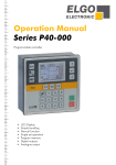
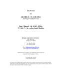
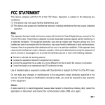
78800xxx / /Rev. 79900347 Rev.07/ /08.03.2014 28.03.2014 Operation Manual SERIES P40-000 Programmable controller LCD Display Simple handling Manual function Single set operation Program memory Digital outputs Analogue output Translation of original User Manual Publisher Technical Support ELGO Electronic GmbH & Co. KG AG Carl-Benz-Str. 1 D-78239 Rielasingen +49 (0) 7731 9339 – 0 +49 (0) 7731 2 13 11 [email protected] Document- No. Document- Name Document- Revision 79900347 P40-000-E_13-14 Rev. 7 Issue Date 28.03.2014 Copyright © 2014, ELGO Electronic GmbH & Co. KG AG -2- Content 1 Content 1 Content ................................................................................................... 3 2 General ................................................................................................... 5 2.1 2.2 2.3 2.4 2.5 Information Operating Manual ............................................................................. 5 Terms and Abbreviations ...................................................................................... 5 Explanation of Symbols ........................................................................................ 6 Statement of Warranties ....................................................................................... 7 Demounting and Disposal .................................................................................... 7 3 Safety ...................................................................................................... 8 3.1 3.2 3.3 General Causes of Risk........................................................................................ 8 Personal Protective Equipment............................................................................... 8 Conventional Use ............................................................................................... 9 4 Transport and Storage ........................................................................... 10 4.1 4.2 4.3 4.4 Safety Instructions for Transport, Unpacking and Loading ........................................ 10 Handling of Packaging Material .......................................................................... 10 Inspection of Transport ...................................................................................... 10 Storage ........................................................................................................... 10 5 Product Features .................................................................................... 11 6 Technical Information ............................................................................ 12 6.1 6.2 6.3 Identification .................................................................................................... 12 Dimensions ...................................................................................................... 12 Technical Data ................................................................................................. 12 7 Design und Function .............................................................................. 14 7.1 Function of keys................................................................................................ 14 8 Operation and Operation Modes ........................................................... 16 8.1 8.2 Operation Modes ............................................................................................. 16 Referencing...................................................................................................... 19 9 Installation and First Start-Up ................................................................ 20 9.1 9.2 9.1 Operating Area ................................................................................................ 20 Mounting / Installing ......................................................................................... 21 Activation of the device ...................................................................................... 21 10 Menu Structure, Sections and Parameters .............................................. 22 11 Menu Axis ............................................................................................. 23 11.1 11.2 11.3 11.4 Menu Axis - Distances........................................................................................ 23 Menu Axis - Times ............................................................................................. 28 Menu Axis - Analog ........................................................................................... 30 Menu Axis - Settings .......................................................................................... 33 -3- Content 12 Menu System ......................................................................................... 40 12.1 12.2 12.3 Menu System – Setup ........................................................................................ 40 Menu System – Times ........................................................................................ 43 Menu System – I/O Configuration ....................................................................... 44 13 Menu Password ..................................................................................... 49 14 Menu Diagnosis / Error Messages .......................................................... 50 14.1 14.2 Menu Diagnosis ............................................................................................... 50 Error Message .................................................................................................. 50 15 Menu Contrast....................................................................................... 51 16 Parameter Table .................................................................................... 52 17 I/O Configuration Table ........................................................................ 56 18 Pin Assignment ...................................................................................... 58 18.1 18.1 Overview connector pin assignment ..................................................................... 59 Connection Example ......................................................................................... 61 19 Disturbances ......................................................................................... 62 19.1 19.2 Fault Clearance ................................................................................................ 62 Re-Start after Fault Clearance ............................................................................. 63 20 Accessory .............................................................................................. 64 21 Maintenance ......................................................................................... 65 22 Cleaning ............................................................................................... 65 23 Type Designation ................................................................................... 66 24 Index ..................................................................................................... 67 -4- General 2 General 2.1 Information Operating Manual This manual contains important information regarding the handling of the device. For your own safety and operational safety, please observe all safety warnings and instructions. Precondition for safe operation is the compliance with the specified safety and handling instructions. Moreover, the existing local accident prevention regulations and the general safety rules at the site of operation have to be observed. Please read the operating manual carefully before starting to work with the device! It is part of the product and should be kept close to the device and accessible for the staff at any time. The illustrations in the manual are for better demonstration of the facts. They are not necessarily to scale and can slightly differ from the actual design. 2.2 Terms and Abbreviations Table 1 Abbreviation Abbreviation/ Term NC Explanation Not connected -5- General 2.3 Explanation of Symbols Special notes in this manual are characterized by symbols. The notes are introduced by signal words which express the magnitude of danger. Please follow this advice and act carefully in order to avoid accidents and damage and injuries. Warning notes: DANGER! This symbol in connection with the signal word “Danger” indicates an immediate danger for the life and health of persons. Failure to heed these instructions can result in serious damage to health and even fatal injury. WARNING! This symbol in connection with the word „Warning” means a possibly impending danger for the life and health of persons. Failure to heed these instructions can result in serious damage to health and even fatal injury. CAUTION! This symbol in connection with the signal word “Caution” indicates a possibly dangerous situation. Failure to heed these instructions can lead to minor injuries or damage of property. Special safety instructions: DANGER! This symbol in connection with the signal word “Danger” indicates an immediate danger for the life and health of persons due to voltage. Failure to heed these instructions can result in serious damage to health and even fatal injury. The operations may only be carried out by a professional electrician. Tips and recommendations: NOTE! … points out useful tips and recommendations as well as information for an efficient and trouble-free operation. References: ( 1.2) ( DOC 3.4) Marks a reference to chapter 1.2 of this manual. Marks a reference to chapter 3.4 of the document DOC. -6- General 2.4 Statement of Warranties The statement of warranties is enclosed separately in the sales documents. Guarantee The producer guarantees the functional capability of the process engineering and the selected parameters. The period of warranty is one year and begins with the date of delivery. 2.5 Demounting and Disposal Unless acceptance and disposal of returned goods are agreed upon, demount the device considering the safety instructions of this manual and dispose it with respect to the environment. Before demounting: Disconnect the power supply and secure against re-start. Then disconnect the supply lines physically and discharge remaining energy. Remove operational supplies and other material. Disposal: Recycle the decomposed elements: Metal components in scrap metal Electronic components in electronic scrap Recycle plastic components Dispose the remaining components according to their material consistence CAUTION! Wrong disposal causes environmental damages! Electronic scrap, electronic components, lubricants and other auxiliary materials are subject to special refuse and can only be disposed by authorized specialists! Local authorities and waste management facilities provide information about environmentally sound disposal. -7- Safety 3 Safety CAUTION! Please read the operating manual carefully, before using the device! Observe the installation instructions! Only start up the device if you have understood the operating manual. The operating company is obliged to take appropriate safety measure. The initial operation may only be performed by qualified and trained staff. 3.1 General Causes of Risk This chapter gives an overview of all important safety aspects to guarantee an optimal protection of employees and a safe and trouble-free operation. Non-observance of the instructions mentioned in this operating manual can result in hazardous situations. 3.2 Personal Protective Equipment Employees have to wear protective clothing during the installation of the device to minimize danger of health. Therefore: Change into protective clothing before performing the works and wear them throughout the process. Additionally observe the labels regarding protective clothing in the operating area. Protective clothing: PROTECTIVE CLOTHING … is close-fitting working clothing with light tear strength, tight sleeves and without distant parts. It serves preliminarily for protection against being gripped by flexible machine parts. Do not wear rings, necklaces or other jewellery. PROTECTIVE GLOVES … for protecting the hands against abrasion, wear and other injury of the skin. PROTECTIVE HELMET … for protection against injuries of the head. -8- Safety 3.3 Conventional Use The ELGO-Positioning Controller is only conceived for the conventional use described in this manual. The device type P40- ELGO- Positioning Controller only serves positioning (distances). CAUTION! Danger through non-conventional use! Non-intended use and non-observance of this operating manual can lead to dangerous situations. Therefore: Only use the device as described Strictly follow the instructions of this manual Avoid in particular: Remodelling, refitting or changing of the construction or single components with the intention to alter the functionality or scope of the device. Claims resulting from damages due to non-conventional use are not possible. Only the operator is liable for damages caused by non-conventional use. -9- Transport and Storage 4 Transport and Storage 4.1 Safety Instructions for Transport, Unpacking and Loading CAUTION! Transport the package (box, palette etc.) professionally. Do not throw, hit or fold it. 4.2 Handling of Packaging Material Notes for proper disposal: 2.3 4.3 Inspection of Transport Check the delivery immediately after the receipt for completeness and transport damage. In case of externally recognizable transport damages: Do not accept the delivery or only accept under reserve. Note the extent of damages on the transportation documents or delivery note. File complaint immediately. NOTE! Claim any damage immediately after recognizing it. The claims for damage must be filed in the lawful reclaim periods. 4.4 Storage Store the device only under the following conditions: Do not store outside Keep dry and dust-free Do not expose to aggressive media Protect from direct sun light Avoid mechanical shocks Storage temperature ( 6.3 Technical Data) needs to be observed Relative humidity ( 6.3 Technical Data) must not be exceeded Inspect packages regularly if stored for an extensive period of time (>3 months) - 10 - Product Features 5 Product Features The positioning controller of P40 series is applicable to easy positioning tasks. An important feature is the easy structured function menu. It allows a quick and comfortable setting of the target value, if necessary a specific quantity of desired pieces. Target and actual value of the axes plus quantity will be displayed on the front panel. The keyboard is simple and user-friendly. With the keyboard the target and the actual value can be forced and the positioning can be started. The P40 series has an internal program memory for up to 1000 lines. For the positioning two different kinds of output signals are available: Switch mode positioning and PID-analogue output. The P40 series can alternatively be supplied with 24VDC. Overview of essential features: • Single or Two Axis-Controller • Analogue or digital outputs for 1 - 3 speed operation • 16 free programmable digital in-/outputs (optional 8 digital in-/outputs) • Program memory for up to 1000 sets Grundbetriebsarten: The P40 consists of three general operation modes: Manual: Single: Program: Inching operation moves the single axes manually by operating the keypad. A whole set can be processed. In the program mode data sets can be strung together or programmed. This set of records is then processed sequentially. The program consists of several different data sets. - 11 - Technical Information 6 Technical Information 6.1 Identification The type label serves for the identification of the unit. It is located on the housing of the positioning controller and gives the exact type designation. When corresponding with ELGO always indicate this data. 6.2 Dimensions 6.3 Technical Data Table 2 Technical Data P40 Elgo-Positioning Controller Input supply voltage Power consumption 24 VDC +10/-20% Rotary encoder supply unit +24 VDC; max. 150 mA (no-load condition)-permitted current on all consumer (incl. own consumption) is 1A 24 VDC (optional 5VDC); max. 130 mA Analogue input (optional) 12 Bit resolution at 3,3 V Supply measuring system Input signals The Pin assignment of the inputs and the input logic (high/low active) are programmable. Minimum pulse duration: 300 ms Input voltage/Pin: max. 10 mA The Pin assignment of the outputs and the output logic (high/low-active) are programmable (PNP). Permissible output voltage: max 150 mA per output / 500 mA total voltage via all outputs Free wheel control: is integrated for inductive load (clamps voltage at the output max. -45V) Outputs are permanent short circuit ( no multiple shorts possible) Output signals Actual value memory E² Prom Durability: 105 On-Off-Switch-Cycles or 10 years Connection technology Industry standard connectors (3,81mm grid, lockable) Display LCD Dot-Matrix 120 x 80 pixel with white backlight - 12 - Technical Information P40 Elgo-Positioning Controller Hardware 32-Bit-Microprocessor with 1 MByte Flash 56 Kbyte RAM System accuracy +/ -1 Increment Input frequency 100 kHz Front cover dimensions W x H = 144 mm x 144 mm Disruption degree W x H = 137 mm x 137 mm Inst. depth without connector 40 mm Inst. depth with connector 75 mm Operating temperature 0 to +45 °C Storage temperature -20 to +50 °C - 13 - Design und Function 7 Design und Function 7.1 Function of keys Escape Menu Navigation Operation Mode Function keys Start Input Stop Change Operation mode between „Manual“ and „Single“ Operation Mode “Program” (only at activated program mode) Activating (pressing 3 sec.) or exiting of the Operation Mode or a Sub menu(pressing shortly). Select or Confirm Cursor navigation „up“ Cursor navigation „down“ ... Function keys (addicted to Menu or Operation mode) Clear or reset an input Change of sign ... Enter Target Value or Parameter value - 14 - Design und Function Start positioning Stop positioning 7.1.1 Function of Display Program Number Dataset Symbol operating mode Absolute / Incremental Position Actual Value Target Options Counter Program-Counter Page through the data sets NOTE! Display elements can vary depending on control mode and configuration. - 15 - Operation and Operation Modes 8 Operation and Operation Modes 8.1 Operation Modes Depending on the configuration and operation mode the different values can be changed and the function buttons can be used differently. 8.1.1 Manual Mode In this mode you can move the axes manually. To do this, select the corresponding axis with the cursor and change the position via the functional keys (F1 / F3). ① ② ④ ③ ① Display of actual value of corresponding axis. ② Key-F1: Move axis in negative direction. ③ Key –F3: Move axis in negative direction. ④ Taste-F2: Referencing of corresponding axis. Select corresponding target value of the axis with the cursor and press Key-F2 more than 2 seconds. Note! With the Menu Axis -> times -> “manual change” a time can be forced. If you move manually, there is a change from creep speed to fast speed, after the expiration of the adjusted time. see Chapter “Axis Menu – Times” and Chapter „Parameter Table“ Axis Parameter / Times „manual change “ Referencing: see Chapter „ Referencing “ , “Menu Axis-Settings” and “Parameter Table” - 16 - Operation and Operation Modes 8.1.2 Single Mode After setting of nominal values and confirmation of with the Start-Key, all active axes will be moved simultaneously in this mode. ② ① ③ ④ ① Display of actual value of corresponding axis. Incremental positionig: target value is absolute position target value is incremental position + target value is incremental position - ② Display if target value of corresponding axis. ③ Setting field for quantities. ④ Key-F2: Referencing of corresponding axis. Select corresponding axis with the cursor and press Key-F2 more than 3 seconds. NOTE! Incremental Positioning: Select corresponding axis with the cursor and change positioning mode by pressing the Enter-Key. see Chapter “Axis Menu – Settings” Referencing: see Chapter „ Referencing “, “Menu Axis-Settings” and “Parameter Table” - 17 - Operation and Operation Modes 8.1.3 Program Mode Using the program mode the user has the possibility to summarise several sets to a program. Depending on the configuration different program flows are possible. ② ① ③ ④ ⑤ ⑥ ⑦ ① Set program number and confirm with Enter-Key. Incremental positionig: target value is absolute position target value is incremental position + target value is incremental position - ② Field display actual dataset and end of program (example. 3E = 3 last dataset) ③ Display of actual value of corresponding axis. ④ Display if target value of corresponding axis. ⑤ Setting field for quantities. ⑥ Key F1: Previous dataset. ⑦ Key F2: Next dataset Setting a Program The program mode is selected through the program key. To be able to generate a program, you first have to assign a program number and confirm with the enter key. On this Program you then load the corresponding data sets. The keys “F1” and “F3” serve to navigate through the various program data sets. It is also possible to select a data set directly, by entering the set number in the corresponding input field and pressing the enter key. After entering the required data sets the program end has to be marked. For this you need to press the “F2” key in the input field. From this moment on, the program end is marked with the letter “E” behind the last set number. Processing a Program The program mode can be selected directly by using the program key. First, choose a program by entering a program number and confirm it with the enter key. With the keys F1 and F3 you can scroll again through all the sets. The automatic positioning starts by pressing the start key. Now, all data sets will be processed in dependency of the set parameters until the end marker of the program is reached. The positioning process can be intercepted by pressing the stop key at any time and the program then remains in the current set. To continue the program, press the start button again. - 18 - Operation and Operation Modes NOTE! The end of program is necessarily needed for the automatic run. In case of missing end of program a warning is displayed. Incremental Positioning: Select corresponding axis with the cursor and change positioning mode by pressing the Enter-Key. see Chapter “Axis Menu – Settings” 8.2 Referencing In the manual mode and single mode the axes can be referenced. Depending on the setting in „AxesParameters -> Settings -> Mode reference“ the following applies: Mode 1, 3, 5, 7: The “F2” key has to be pressed for at least 2 sec. With a two-axes controller, the reference symbol of the corresponding axis has to be displayed (in the manual mode the corresponding axis needs to be selected, in the single mode the target value of the corresponding axis needs to be selected). Mode 2, 4, 6, 8: an external Input has to be activated in order to reference Mode 1 o. 2: the value stored in the Menu Axis-> Axis -> Distances -> reference is taken as the current actual value for the axis Mode 3 o. 4: the value entered for target position is taken as the current actual value. Mode 5 o. 6: Reference drive to switch end-position positive with index pulse. (see next Chapter) Mode 7 o. 8: Reference drive to switch end-position negative with index pulse. (see next Chapter) 8.2.1 Function of Reference Drive The controller moves to the axis that needs to be referenced in dependence of the parameter: Menu Axis Axis General Axis Parameter Mode reference. The output “reference drive run” is set. If the corresponding input (switch end-position positive or negative) is activated, the controller stops. After a dwell time it moves in the opposite direction. Once the appropriate input (switch end-position) is disabled, the index pulse will be released. For the next zero pulse the controller stops and the reference value stored in the parameter: Menu AxisAxis DistancesReference will be transferred in the actual value window. - 19 - Installation and First Start-Up 9 Installation and First Start-Up CAUTION Please read the operating manual carefully before using the device! Strictly observe the Installation instructions! In case of damage caused by failure to observe this operating manual, the warranty expires. ELGO is not liable for any secondary damage and for damage to persons, property or assets. The operator is obliged to take appropriate safety measures. The first start-up may only be performed by staff that has been trained and authorized by the operator. 9.1 Operating Area WARNING! Do not use the device in explosive or corrosive environments! The device must not be installed close to sources of strong inductive or capacitive interference or strong electrostatic fields! CAUTION! The electrical connections must be made by suitably qualified personnel in accordance with local regulations. The device may be designed for switchboard mounting. During work on the switchboard, all components must be de-energized if there is a danger of touching the energized parts! (protection against contacts) Wiring works may only be performed in the de-energized state! Thin cable strands have to be equipped with end sleeves! Before switching on the device, connections and plug connectors have to be checked! The device must be mounted in a way that it is protected against harmful environmental influences such as splashing water, solvents, vibration, shock and severe pollution and the operating temperature must not be exceeded. - 20 - Installation and First Start-Up 9.2 Mounting / Installing For the installation of the device an opening according the disruption degree (see Chapter “Technical Data”), must be cut in machine chassis. The device is tensed up by two studs and two swiveling flaps, screwed on in the case, with the machine chassis (included in delivery). Only a screwdriver is necessary for this. 9.1 Activation of the device The device starts automatically after operation voltage application. - 21 - Menu Structure, Sections and Parameters 10 Menu Structure, Sections and Parameters Operating Modes Manual Mode Single Mode Program Mode Service (press 3 sec the “ESC-Key”) Parameter axis X-axis System Distances Times Analogue (only with Option PID ) General Parameter Y-axis (only with 2 axes- version) Distances Times Analogue (only with Option PID ) General Parameter Settings System-times I/O-configuration Input function Input logic Output function Output logic Default parameter Password Diagnosis Input Output Keyboard Version NOTE! The service operation/parameter level can be reached by holding the “ESC” button for about 3 seconds. Most of the parameters, if not otherwise designated can only be changed after entering the password/ PIN code. PIN CODE: 250565 - 22 - Menu Axis 11 Menu Axis 11.1 Menu Axis - Distances Relevant distances for the axes can be set in this menu. Axis distances Access to parameters concerning distances e.g. speeds etc. Axis times Access to parameters concerning times e.g. position reached, zero speed monitoring, rotary encoder etc. Axis analogue Access to parameters concerning the analogue output. Axis settings Access to general parameters concerning the axes. Slow forward Creep forward Correction stop forward Slow backward Creep backward Correction stop backward Tolerance window Manipulation Spindle compensation Forced loop Reference value Retract length End position Min End position Max Factor Displacement Tool correction Fix position - 23 - Menu Axis Slow forward/slow backward = middle speed This parameter serves the input of the distance, at which the controller switches from high speed to slow speed before reaching the target position. Creep forward/creep backward = slow speed This parameter serves the input of the distance, at which the controller switches from slow speed to creep speed before reaching the target position. Correction stop forward/correction stop backward Here a constant overrun can be compensated. Example: The target position is overrun by 0.2 mm constantly. The data entry has to be 0.2mm. The stop command is then moved forward by 0.2 mm. When starting the operation the stop offset is set first to "0" in order to be able to calibrate the overrun accurately. For an exact positioning the stop offset should be as small as possible (0.0 to 0.2 mm) i.e. the mechanical friction should be steady over the entire run distance and the slow speed and/or creep speed must be adjusted accordingly small. NOTE! When positioning with PID, the correction stop serves as tolerance window. - 24 - Menu Axis Example: Positioning with two speeds For the adjustment of the parameters generally applies: Slow speed = Creep speed > Correction stop Slow speed: Creep speed: Correction stop: 10,0mm 10,0mm 1,0mm Fast Slow speed/Creep speed Position reached: 100,0mm Correction Stop Slow 99,0mm 90,0mm 100,0mm Example: Positioning with three speeds Here for the adjustment of the parameters generally applies: Slow speed > Creep speed > Correction stop Slow speed: Creep speed: Correction stop: 20,0mm 10,0mm 1,0mm Fast Slow speed Creep speed Position reached: 100,0mm Correction Stop Slow Middle 80,0mm 90,0mm 99,0mm - 25 - 100,0mm Menu Axis Tolerance window If the current actual position of the target position corresponds + / - to the value of "tolerance window", the corresponding output "tolerance zone" (see the main configuration) is set. Manipulation It is possible to adjust the indicator of the actual value of the corresponding axis to the target value within the entered tolerance window. The entered range of tolerance is always active in the + and – range around the demand value. The real actual value is saved in the processor, i.e. no positioning errors add up. Example: Entered Value = 0,2mm (i.e. Tolerance Window +/- 0.2mm) Internal actual value Displayed actual value Target Value 99.8 mm 100.0 mm 100.0 mm NOTE! The tolerance window should be set to zero before starting to operate. Spindle compensation In order to adjust spindle or sprocket tolerances the target position must always be approached from the same direction, i.e. in one direction the target position will be overrun by the entered value. After expiration of the time that was entered in menu/times/backlash dwell the entered target position will be reached again. Forced loop If the actual value is within the range target value +/- value of forced loop window during an absolute positioning a forced loop is moved. Reference value A reference value and a reference position can be forced in this parameter. Retract length When activating the external retract input, the axis moves depending on the retract mode (see Chapter „ Menu Axis - Settings -> Retract Mode”) around this value or on this value. - 26 - Menu Axis Software-end position minimum/maximum These two values can be used if no mechanical switch end-positions are present or additionally for already existing mechanical switch end-positions. End position min.: This value should be between the smallest length/position that has to be proceeded and zero (respectively shortly before the mechanical switch end-position). End position max.: This value should be between the largest length/position that has to be proceeded and the maximum length (respectively shortly before the mechanical switch end-position). Factor The factor for analysis of the pulses is set here. NOTE! As of the Software Version 1.64 the decimal point (number of positions after decimal point) is calculated automatically. The controller has 4-edge-triggering! Displacement (no PIN necessary) Here positive or negative dimensions are programmed, which are added to the actual value by activating an allocated input. Tool correction (Saw blade) (no PIN necessary) In the incremental measurement mode this correction value is automatically added, i.e. the positioning process continues working off to this value Fix Position Length values to control the length limit stop axes can be set here. If the set values are reached / passed the corresponding output is . - 27 - Menu Axis 11.2 Menu Axis - Times The times relevant for the respective axis can be entered here. Axis distances Access to parameters concerning distances e.g. speeds etc. Axis times Access to parameters concerning times e.g. position reached, zero speed monitoring, rotary encoder etc. Axis analogue Access to parameters concerning the analogue output. Axis settings Access to general parameters concerning the axes. Position reached Spindle compensation Manual change Monitoring Delay Control enable Start delay Shutdown control Retract time Delay retract Reference time Quantity reached - 28 - Menu Axis Position reached The output signal is based on a variable time during input of a time value or statically/maintained (axis in position) if the value is set to 0. It is set if the according axis has reached the target position. Spindle compensation In the peak of the loop drive, the drive signals decline. The controller returns to the target value when the parameterized time has expired (adjustment range 0.0 sec. … 99.9 sec.). If the value is zero, there is no waiting period at the peak. Manual change Here the time in manual mode can be entered to set the speed from the low speed to the next higher speed. Monitoring Here a time (adjustment range 0.0 sec. ... 99.9 sec.) is set to monitor the measurement system. If there are no signals from the measuring system during the programmed period of time, the drive signals are switched off to stop the engine. If the value is zero the monitoring is deactivated. Delay control enable After the start command the output “control enable” is activated. After reaching the target position and only after the expiration of the programmed time (adjustment range 0.0 sec. … 99.9 sec.) in the parameter “fall delay time control enable” the output is set back. If the parameter “delay control enable” is at the value of zero, the output for the control enable is adjusted statically and remains set until a change of operation modes respectively until activating the stop key. Start delay At a starting command the start of the positioning is delayed for the entered time. Shutdown control Here the time for shutdown after the position is reached is entered (adjustment range 0.0 sec. ... 99.9 sec.). Retract time The dwell-time at the peak is entered here (adjustment range 0.0 sec. …99.9 sec.). After this time the position control is set back from the retract peak to the target value. In addition this value is also used for a retraction on time. Delay retract The retract is delayed for the entered time. Reference time In the peak of the reference run, the drive signals decline. The controller will continue positioning when this time has expired (adjustment range 0.1 sec. ... 99.9 sec.). Quantity reached Here the time is entered in 0.1 sec. for the signal “quantity reached”. If the value = 0, the output “quantity reached” is statically set. - 29 - Menu Axis 11.3 Menu Axis - Analog The axis relevant analogue parameters can be set in this menu. Axis distances Access to parameters concerning distances e.g. speeds etc. Axis times Access to parameters concerning times e.g. position reached, zero speed monitoring, rotary encoder etc. Axis analog Access to parameters concerning the analogue output. Axis settings Access to general parameters concerning the axes. Velocity Acceleration P-Portion I-Portion D-Position I-Limit Impulses encoder Start mode Stop mode Stop mode manual Manual fast Manual slow v Reference mode 1 v Reference mode 2 U fast forward U slow forward U creep forward U fast backward U slow backward U creep backward NOTE! The parameters for analogue mode are only of interest for devices with option PID. - 30 - Menu Axis Velocity The maximum speed is set in this parameter, in rpm. Should there be gearing between the motor and the measuring system, this has to be considered in the calculations (e.g. gear or spindle) Example! Demanded (below the maximum possible !) motor speed rpm = 3000 Gearing ratio i = 10 V = rpm/i = 3000 rpm/10 = 300 rpm Acceleration The acceleration during positioning is set in this parameter in revolutions per square second ( [U ] ). [s 2 ] Also here you have to consider possible gearing ratio. P-Portion Proportional amplification: setting range 1 ... 99999 General: The P-controller exclusively consists of a proportional portion and has thereby its reinforcing characteristic. The P-term multiplies the input value with a constant coefficient. P40: At offset the difference between the target and actual value is multiplied with the entered value and shown as power-sharing. The bigger the proportional amplification the more sensitive the control loop will be (possibly even unstable). I-portion / I-Limit Integral step: setting range 1 ... 99999 General: An I-controller (integrating controller) determines the control value through timed integration of the offset taking the reset time into account. A continuing offset leads to further increase of the analogue output. The reset time determines how big the temporal influence is. The maximum reset time is limited through I-limit. The step response of the I-portion is a linear increase. That means for a constant offset the integral will be increased and thus reinforces the I-portion. P40: At offset the analogue control voltage will continue to increase step by step until there is zero difference between the target and actual position and the entered I-limit in this parameter is reached respectively. The greater the I-portion, the slower is the response. - 31 - Menu Axis D-portion Differential voltage: setting 1...1000 General: The D-controller (differential controller) determines the control value from the derivative with respect to time of the offset. P40: At offset a short voltage pulse proportional to the rate of change will be put out to compensate quickly without sacrificing the stability of the control loop permanently. The value of the voltage pulse is entered. (max + / - 10 V). Impulses encoder (rotary encoder resolution) The number of pulses per revolution of the engine is entered in this parameter. This enables amongst others the calculation of speed to be effected (max. 9999 pulses per revolution). Start mode Wert Modus 0 Is the axis in the space of the tolerance zone the axis will not be restarted. 1 Start of axis in the tolerance zone will be forced. Stop mode / Stop mode manual Value Mode 0 the voltage of the analogue output is set to 0V 1 the drive is set to shut down through the highest possible acceleration 2 the drive is set to shut down through an acceleration according to the adjusted parameter Manual fast Here the speed “fast” for moving the axis in manual mode can be defined. Manual slow Here the speed „slow“ for moving the axis in manual mode can be defined. v Reference mode 1 Here the reference run speed of the stopping point until reaching the initiator is defined. v Reference mode 2 Here the reference run speed of stopping point until reaching the index pulse is defined. U fast / slow / creep speed forward Voltage during fast / slow / creep speed forward. U fast / slow / creep speed backward Voltage during fast / slow / creep speed backward. - 32 - Menu Axis 11.4 Menu Axis - Settings System relevant general parameters can be entered in this parameter. Axis distances Access to parameters concerning distances e.g. speeds etc. Axis times Access to parameters concerning times e.g. position reached, zero speed monitoring, rotary encoder etc. Axis analogue Access to parameters concerning the analogue output. Axis settings Access to general parameters concerning the axes. Axis type Button manual mode Drive signal configuration Reference mode Spindle compensation mode Software end-position Hardware end-position Retract mode Error compensation Piece counter Incremental positioning Decimal point Display option manual Unit - 33 - Menu Axis Axis type The type of axis is defined. Digital + CPU (use with positioning through digital drive signals) Digital + PID (use with PID version) Button manual mode The function of the keys in manual mode is defined in this parameter. off (The buttons F1, F3 on the control are deactivated for the according axis. This axis can only be moved via the correspondingly assigned inputs.) normal inverted Drive signal configuration With configuration of the drive signals different starting combinations for the corresponding speeds can be adjusted. Drive signals Mode 1 3 speeds Speed = output signals 1-3 ascending Output 4 sets direction reverse Output signals Creep forward Slow forward Fast forward Creep backward Slow backward Fast backward 1 X X X X X X 2 3 X X X X X 4 X X X X Drive signals Mode 2 2 speeds ((ELGO Standard) Independent outputs for forwards and reverse Independent outputs for fast and slow Output signals Creep forward Slow forward Fast forward Creep backward Slow backward Fast backward 1 X 2 X X 3 4 X X X X Signal configuration: Forwards: Creep speed: Fast speed: Backwards: X - 34 - Drive signal 1 Drive signal 2 Drive signal 3 Drive signal 4 Menu Axis Drive signals Mode 3 2 speeds speed = output signals 2 + 3 output 4 set direction reverse Output signals Creep forward Slow forward Fast forward Creep backward Slow backward Fast backward 1 X 2 X X X X 3 4 X X X X X Drive signals = Mode 4 2 speeds Independent outputs for direction and speed Output signals Creep forward Slow forward Fast forward Creep backward Slow backward Fast backward 1 X 2 3 4 Signal configuration: Forwards: Forwards fast: Backwards: Backwards fast: X X X Drive signals = Mode 5 3 speeds Speed forward = output signals 1-3 ascending Speed backward = always fast output 4 sets direction reverse Output signals Creep forward Slow forward Fast forward Creep backward Slow backward Fast backward 1 X X X X X X 2 3 4 X X X X X X X X X X X X - 35 - Drive signal 1 Drive signal 2 Drive signal 3 Drive signal 4 Menu Axis Drive signals = Mode 6 3 speeds Binary coded output 1 = forward output 4 = backward outputs 2+3 = speed Output signals Creep forward Slow forward Fast forward Creep backward Slow backward Fast backward 1 X X X 2 X X X X 3 4 X X X X X X X Drive signals = Mode 7 3 speed Forward/backward separately Output signals Creep forward Slow forward Fast forward Creep backward Slow backward Fast backward 1 X X X 2 3 X X X X X X 4 X X X Reference mode (see Chapter “Operation and Operation Modes”) Mode 1 Mode 2 Mode 3 Mode 4 Mode 5 Mode 6 Mode 7 Mode 8 Reference via parameter with “F2”- button * Reference via parameter & external input * Reference via Target value & “F2” button Reference via Target value & external input ** Reference drive pos. via parameter with “F2” button ** Reference drive pos. via external input. ** Reference drive neg. via “F2” button ** Reference drive neg. via external input ** * see axis parameters axis distances reference value ** see axis parameters axis time reversion Ref. drive Extra on PID – positioning: Menu Axis Axis Analogue v. Ref. drive part 1 v. Ref. drive part 2 Above the “F2”-button the reference symbol of the corresponding axis is displayed External input has to be allocated. - 36 - Menu Axis Installation / Initial Operation Spindle compensation mode No spindle compensation Negative spindle compensation Positive spindle compensation + With forced loop With forced loop + Software end-position all end positions active end position min deactivated end position max deactivated all end positions deactivated Hardware end-position all end positions active end position min (defined input) deactivated end position max (defined input) deactivated all end positions deactivated Retract mode Mode 1 Descent/retract to actual value + adjusted value* Mode 2 Descent/retract to adjusted value* Mode 3 Descent/retract positive to actual value for the adjusted time period** Mode 4 Descent/retract to actual value + adjusted value* without return Mode 5 Descent/retract to adjusted value* without return Mode 6 Descent/retract positive to actual value for the adjusted time period** without return Mode 7 Descent/retract to actual value – adjusted value* Mode 8 Descent/retract negative to actual value for the adjusted time period** Mode 9 Descent/retract to actual value – adjusted value* without return Mode10 Descent/retract negative to actual value for the adjusted time period** without return * see Menu Axis Axis Distances descent/retract distance ** see Menu Axis Axis Times descent Error compensation Here the activity of the error compensation is defined for incremental measurement positioning. off on - 37 - Menu Axis Piece Counter With this parameter the counter mode will be set into the “single mode”. without counter auto decrement * auto decrement + Stop * auto increment * auto decrement/ increment * decrement ** decrement + Stop ** increment ** decrement/ increment ** - With the function “Counter increment”, it is counting up from the current actual value. - With the function “Counter decrement”, it is counting towards zero. - With the function “counter decrement/increment”, it is decrementing if a certain number of items have been assigned. If it reaches zero, the number of units corresponding to the time stored in the parameter “times-axes-quantity reached” is set for a time and not static. Then the counter is incrementing. * reaching the position the counter will be activated ** with the input quantity the counter will be activated. Incremental positioning Here the option “absolute / incremental Positioning” is activated. off on extern no selection possible, always absolute positioning selection via keypad possible selection via external inputs possible If this function is activated, one of the following Symbols (see Fehler! Verweisquelle konnte nicht gefunden werden. Display Elements) is displayed. target value is absolute position target value is incremental position + target value is incremental position - There is always an absolute measurement, if there is none of the signs on the display and if the function is deactivated. Decimal point Here the decimal point is defined. Display option manual Here the image of the manual button will be defined. left – right down – up forwards – backwards - 38 - Menu Axis Unit The displayed unit can be specified here: mm, inch or degree. NOTE! The units of the parameters remain unchanged! - 39 - Menu System 12 Menu System 12.1 Menu System – Setup Setup Access to system parameters. System-times Access to system parameters concerning times. I/O Configuration Reset to factory parameters Default parameter Enter the Password Language Axes active (only with two-axes-version) Piece Counter program Auxiliary Counter Number of programs Next set stepping Options Operating modes PIN before Parameter Sequence of axis (only with two-axes-version) System equip NOTE! Setting the default parameters! In two axes version the P40 default parameters for I/O configuration are set with dependency to the occupancy of the active axes. X-Axis active: I/O configuration of the single-axis-version X & Y- axes active: I/O configuration of the two-axes-version - 40 - Menu System Language German English French Spanish Italian Polish Chinese Axes active (only with two-axes-version) X-Axis X-Axis and Y-Axis Piece counter program With this parameter the piece counting mode is terminated in the option “program”. without decrementing incrementing no piece counter activated when position reached, piece counting is activated piece counting is activated via external input If the piece counter reaches zero, the output is adjusted for a time corresponding to the time stored in parameter “system-> times-> piece counter program”. In addition a next program step can be activated (this depends on further parameters). Auxiliary counter This parameter determines if an additional counter is available. without auxiliary counter Program Auto-Program If the program counter is activated, it can be defined in the option „program“, how many times the program should run through. If the program counter reaches zero, a new value entry is forced (even at default of zero). With the function Auto program the next position will be automatically hit after a piece counting pulse (“piece counter program” has to be configured decrementing). Number of programs 1 2 5 10 20 25 40 50 = 1000 sets = 500 sets = 200 sets = 100 sets = 50 sets = 40 sets = 25 sets = 20 sets - 41 - Menu System Next set stepping For the program mode, you can select the following for the next set stepping: without no next step setting activated quantity reached after expiration of the piece counter of the current set, the next set will be loaded quantity, set 1 same as “quantity reached”, additionally set 1 will be loaded after program end Options off on Auxiliary functions are activated. Input field appears in the display and outputs can be assigned. See also system -> I/O-configuration -> output functions and system -> system-times -> clamp auxiliary function Operating modes This parameter determines which modes are possible single set single set+ manual single set+ program single set+ manual + program Pin before parameter This parameter determines if the service/parameter-level can be achieved with or without PIN entry. off can be looked at without Pin entry, but cannot be changed on parameters can only be changed with the password “250565”. Sequence of axis (only with two-axes-version) This parameter determines in which sequence the axes are going to drive: X-axis, Y-axis (Y-axis drives after X-axis) Y-axis, X-axis (X-axis drives after X-axis) X-axis + Y-axis (axes drive at the same time) System equip off on diverse parameters are turned off - 42 - Menu System 12.2 Menu System – Times Setup Access to system parameters. System-times Access to system parameters concerning times. I/O Configuration Here the inputs and outputs are assigned. Default parameter Reset the parameters Next set stepping Clamping off Edit-mode timeout Piece counter program Clamp auxiliary function Next set stepping This is the time setting in seconds (0.0 – 9.9) how long the controller should wait in the program-mode, with auxiliary counter “auto-program” until the next set is positioned. Clamping off If the function „clamping off“ is assigned to an output (system->I/O-configuration->output-function), the controller is waiting between setting the output and the start of positioning, as well as between resetting the output (after completion of positioning) and the release of the next action for the specified time (0.0 – 9.9). This function is used to release (activate) e.g. a clamping system or brake right before (after) positioning. Edit-mode timeout (no PIN necessary) This is the time until exiting the input mode in seconds (0.0 – 9.9) (standard 3.0) Piece counter program Here the time is defined in seconds (0.0 – 9.9), which presents the signal “quantity reached” in the program mode. If the values = 0, the output “quantity reached is set statically. Clamp auxiliary function If the program mode „next program step“ has been chosen and the parameter system->settings>auxiliary functions has been set to „on“, the auxiliary function outputs are hold for the set time (0.0 – 9.9 in seconds). After this it is switched to the next set. - 43 - Menu System 12.3 Menu System – I/O Configuration Setup Access to system parameters. System-times Access to system parameters concerning times. I/O Configuration Here the inputs and outputs are assigned. Default parameter Reset the parameters Input function Input logic Output function Output logic 12.3.1 Function of the Inputs NOTE! At the inputs „Extern Enable“, “External Stop” and „switch end-pos min/max“, the input logic is per default/factory setting set on “low active” for security reasons (failsafe). External enable The extern enable input is monitored during the positioning. If the input is activated, no positioning is possible respectively it will be cancelled with an error message External start input corresponds to the key „start“ External stop corresponds to the key „stop“ Setting the reference If in the system parameter Reference the mode 2, 4, 6 or 8 is set, the actual value can be calibrated through this input. Mode 2: Reference via external input (Reference value: Parameter-Axis-Distances) Mode 4: Reference via target value + ext. input (Reference value: set target value) Mode 6: Reference positive via external Input Mode 8: Reference negative via external Input - 44 - Menu System Incremental positioning negative If this input is active, the positioning in incremental is in negative direction, if incremental positioning is externally configured (Menu Axis-> settings). Incremental positioning positive If this input is active, the positioning in incremental is in positive direction, if incremental positioning is externally configured (Menu Axis-> settings). Retract function The retract function will be started if the input is activated Piece counter With every pulse at this input the current quantity is increased or decreased by one piece. Setting: Parameter-Axes- settings decrement decrement + stop increment increment/decrement Switch endposition min/max switch end-pos. min switch end-pos. max The switch end-position inputs are monitored during the positioning. If a switch end-position input is activated, no positioning in the corresponding direction is possible respectively the positioning will be cancelled. Key manual mode <Axis +/-> If an input is assigned here, the corresponding axis can be positioned in the corresponding direction via an external key in the manual mode (joystick-function). Tool offset As long as this input is activated, the parameter Menu Axis -> Axis-> Distance ->Tool offset will be added to the actual value. Fix position If the input is activated the axis moves to the fix position. (Menu Axis-> Distances->fix position) Enable axis The input is monitored during the positioning. If the input is activate the positioning is not possible. The positioning is canceled and an error message is set. - 45 - Menu System 12.3.2 Function of Outputs Position reached (variable / static) If “0.0s” is entered in Menu Axis -> Times -> Position reached, the output is static i.e. the output is active, after the target value has been reached. If a value between 0.1 – 99.9s is entered, the output is set on variable i.e. the output is reset after the entered time has expired. Drive Signal The drive signal outputs are configurable via Menu Axis -> General Parameter -> Drive Signal Configuration. Control enable Before a positioning the signal control enable is set. After reaching the target position and only after expiration of the time Menu Axis -> Times -> delay control enable the signal control enable is reset. Quantity reached (variable / static) If “0.0s” is entered in Menu Axis -> Times -> Quantity reached, the output is set statically when the quantity is reached. At „start“ the output is reset. If a value between 0.1 – 99.9s is entered, the output is set variably i.e. the output is reset after expiration of the entered time. Tolerance window <Axis> If the current actual position corresponds to the target value +/- the value Menu Axis -> Axis-> Distance –> Tolerance window, this output is set. Reference drive This output is set during a reference drive Tool enable In manual mode: the output is set when changing into the manual mode and is reset during a positioning. In single- and program-mode: the output is reset when changing in one of these modes and is set after each positioning. The output can be reset with the stop-key. Program-end The output is set, after the set with end marker has been proceeded. If „program“ respectively „auto-program“ has been selected in System -> Settings ->auxiliary counter, the number of program runs has to be reached additionally. Auxiliary function In the single- and program-mode these outputs are set according to display input. Menu System – Times -> Clamp auxiliary function - 46 - Menu System Clamping This output is set before a positioning and is reset after a positioning (e.g. clamping system or activating/releasing the brake) Menu System – Times -> Clamping All axes on position (only two-axes version) If both current actual values correspond to the according target positions +/- Menu Axis -> Axis -> Distance -> Tolerance window, this output is set. Retract s1 axis This output is active during retract. 12.3.3 Configuration of Inputs and Outputs The inputs and outputs can be configured freely with their associated logic 12.3.3.1 Linking of Inputs with Functions In the Chapter “Table of I/O Configurations” you will find an overview of all functions which can be assigned to the inputs. After dialling a function by using the navigation buttons you can select an input for this function by pressing the Enter key. If a previously used input needs to be reset, you can use "delete key" to dial in the "not used" state. It is also possible to press the Enter key repeatedly until “not-used” is displayed. A multiple use of inputs is not possible here. If an input is already used only the next free input can be chosen automatically. 12.3.3.2 Assigning the Logic to input If you have allocated the inputs of the controller with functions, then you can use this menu to define whether the corresponding input function shall be triggered at a logical "High"-level or at a logical "Low"-level. Assigning the logic takes place by selecting the corresponding function and pressing the enter key. - 47 - Menu System 12.3.3.3 Linking of Outputs with functions In the Chapter “Table of I/O Configurations” you will find an overview of all functions of the outputs which can be assigned. After dialling a function by using the navigation buttons you can select an output for this function by pressing the Enter key. If a previously used output needs to be reset, you can use the "delete key" to dial it in the "not used" state. A multiple use of outputs is not possible here. If an output is assigned with a function, only the next free input can be chosen automatically. 12.3.3.4 Assigning the Logic to Outputs For the outputs it is also possible to assign logic depending on the selected output function. The setting follows the same procedure as in Chapter “Assigning the Logic to Inputs “. - 48 - Menu Password 13 Menu Password The password is input in the menu password. NOTE! The service mode / parameter level is saved by password PIN CODE: 250565 After login all parameters can set. Press Enter or Key F2 to confirm your password input. - 49 - Menu Diagnosis / Error Messages 14 Menu Diagnosis / Error Messages 14.1 Menu Diagnosis Here function to test the hardware and to display the current installed hard- and software versions are offered. Inputs Outputs Keypad Version/Info 14.2 Error Message Table 3 Error Messages Error Message Error 16 Meaning hardware end switch minimum axis X active! hardware end switch minimum axis Y active! hardware end switch maximum axis X active! hardware end switch maximum axis Y active! external stop on error active! Error 25 no enable!" Error 01 Error 02 Error 04 Error 05 Error 07 Error 08 Error 10 Error 11 software end position minimum axis X fell below! software end position minimum axis Y fell below! software end position maximum axis X fell above! software end position maximum axis Y fell above! Error 13 no measuring system axis X! Error 14 no measuring system axis Y! power failure. Switch on control again and check the axis-position Error hler 17 Error 18 Possible reasons / correction Check the signals/wires of the corresponding input or deactivate the according input function (see Chapter “Linking of Inputs with functions”) Check the corresponding parameter or deactivate the according software end position (see Chapter “Menu Axis – Settings”) Check the according measuring system respectively its signals/wires Check the according measuring system respectively its signals/wires You have no authorisation to process this function or you have not entered a password (PIN), respectively the wrong one access denied - 50 - Menu Contrast 15 Menu Contrast In this menu the contrast of the display can be configured. Use therefor the following buttons: / - 51 - Parameter Table 16 Parameter Table Table 4 Axis Parameters - Distances Function Setting Range Default Setting Slow forward 0,0 – 9999,9 * Creep forward 0,0 – 9999,9 * 15,0 15,0 Correction stop forward 0,0 – 9999,9 * 0,0 Slow backward 0,0 – 9999,9 * 15,0 Creep backward 0,0 – 9999,9 * 15,0 Correction stop backward 0,0 – 9999,9 * 0,0 Tolerance window 0,0 – 9999,9 * 0,0 Manipulation 0,0 – 9999,9 * 0,0 Spindle compensation 0,0 – 9999,9 * 5,0 Forced loop 0,0 – 9999,9 * 1,0 Reference value -9999,9 – 9999,9 * 0,0 Retract length 0,0 – 9999,9 * 5,0 End position min. -99999,9 – 99999,9 * -2000,0 End position max. -99999,9 – 99999,9 * 2000,0 Factor 0,0 – 9,999999 0,100000 Displacement -9999,9 – 9999,9 * 0,0 Tool correction 0,0 – 9999,9 * 0,0 Fix position -9999,9 – 9999,9 * 0,0 * = dependent on decimal point setting (particulars with 1/10) Table 5 Axis Parameters - Times Function Position reached Setting Range 0,0 – 99,9 [s] Default Setting 1,0 Spindle compensation 0,0 – 99,9 [s] 1,0 Manual change 1,0 Monitoring 0,0 – 99,9 [s] 0,0 – 99,9 [s] Delay Control enable 0,0 – 99,9 [s] 1,0 Start delay 0,0 – 99,9 [s] 0,0 Shutdown control 0,0 – 99,9 [s] 0,0 Retract time 0,0 – 99,9 [s] 1,0 Delay retract time 0,0 – 99,9 [s] 0,0 Reference time 0,0 – 99,9 [s] 1,0 Quantity reached 0,0 – 99,9 [s] 0,0 - 52 - 0,0 Parameter Table Table 6 Axis Parameters - Analog Function Setting Range Velocity 0 – 9999 [U/min] Default Setting 3000 Acceleration 0 – 9999 [U/s²] 50 P-Portion 0 – 99999 5 I-Portion 0 – 99999 3 D- Position 0 – 99999 1 I-Limit 0 – 99999 10 Impulses encoder 0 – 9999 360 Start mode 0,1 1 Stop mode 0,1,2 1 Stop mode manual 0,1,2 1 Manual fast 0 – 9999 [U/min] 2000 Manual slow 0 – 9999 [U/min] 1000 v Reference mode 1 v Reference mode 2 0 – 9999 [U/min] 0 – 9999 [U/min] 500 U fast forward 0 – 9,9 [Volt] 3,0 U slow forward 0 – 9,9 [Volt] 2,0 U creep forward 0 – 9,9 [Volt] 1,0 U fast backward 0 – 9,9 [Volt] - 3,0 U slow backward 0 – 9,9 [Volt] - 2,0 U creep backward 0 – 9,9 [Volt] - 1,0 250 Tabelle 1Calibration of analog Inputs Function minimal comply angle, distance transformer increment maximal comply angle, distance transformer increment Setting Range Default Setting -99999.9 – 99999,9 [ °, mm] 0 0 - 4095 0 -99999.9 – 99999,9 [ °, mm] 90.0 0 - 4095 - 53 - 4095 Parameter Table Table 7Axis Parameters Settings Function Setting Range Default Setting Measuring system - - - drive outputs Axis type Encoder --- Digital Encoder --- PID + Digital Analog --- Digital Encoder - - - Analog+ Digital Analog - - - Analog+ Digital X Button manual mode normal, inverted, off normal Drive signal configuration Mode1, 2, 3, 4, 5, 6, 7, 8 Mode12 Reference mode Mode 1, 2, 3, 4, 5, 6, 7, 8 without with spindle +/forced loop +/both enabled negative disabled positive disabled both disabled both enabled negative disabled positive disabled both disabled Mode11, 2, 3, 4, 5, 6, 7, 8, 9,10 Mode11 off/on without auto decrement auto decrement + Stopp auto increment auto decrement / increment decrement decrement + stop increment decrement / increment off/on off without, 1/10, 1/100, 1/1000 Left-right down-up forward-backward mm / inch / degree 1/10 Spindle compensation mode Software end-position Hardware end-position Retract mode Error compensation Piece counter Incremental positioning Decimal point Display option manual Unit - 54 - without both enabled both enabled Mode11 auto decrement on Left-right mm Parameter Table Table 8 System - Settings Function Setting Range Default Setting Language D / GB / F / E / I / PL / CHN X-axis X- axis + Y- axis decrement without auto decrement without Program Auto-program 1, 2, 5, 10, 20, 25, 40, 50 without quantity reaches quantity reaches + Satz1 without / auxiliary function/ value retract Single Single+ Manual Single+ Program Single+ Manual + Program off/on x- axis , Y- axis Y- axis , x- axis x- axis + Y- axis GB off/on on Function Setting Range Default Setting Next set stepping 0.0 … 9.9 [s] 0.0 Clamping off 0.0 … 9.9 [s] 0.0 Edit-mode timeout 0.0 … 9.9 [s] 2.0 Piece counter program 0.0 … 9.9 [s] 0.0 Clamp auxiliary function 0.0 … 9.9 [s] 0.0 Axes active (only with two-axes-version) Piece Counter program Auxiliary Counter Number of programs Next set stepping Options Operating modes PIN before Parameter Sequence of axis (only with two-axesversion) System equip X- axis + Y- axis auto decrement without 50 quantity reaches without Single+ Manual+ Progr. off x- axis , Y- axis Table 9 System - Times - 55 - I/O Configuration Table 17 I/O Configuration Table Input Function Switch endpos X-min Switch endpos X-max Switch endpos Y-min Switch endpos Y-max Retract X-axis Retract Y- axis Reference X- axis Reference Y- axis Extern enable Extern Start Extern Stop Piece counter X Displacement X Displacement Y Button manual X+ Button manual XButton manual Y+ Button manual YFix position X Fix position Y Start X-axis Start Y-axis Enable X-axis Enable Y-axis ST3 3 4 5 6 Logic ST4 (with Option 16I/O configurable) 7 8 9 10 3 4 5 6 7 8 9 10 default customer L L L L H H H H H H L H H H H H H H H H H H H H "L" corresponds to input "Low-active", "H" corresponds to input "High-active" - 56 - I/O Configuration Table Output Function Drive signal 1 X-axis Drive signal 2 X-axis Drive signal 3 X-axis Drive signal 4 X-axis Drive signal 1 Y-axis Drive signal 2 Y-axis Drive signal 3 Y-axis Drive signal 4 Y-axis Control enable X-axis Control enable Y-axis Position reached X-axis Position reached Y-axis Tolerance zone X-axis Tolerance zone Y-axis Reference drive X-axis Reference drive Y-axis Quantity reached All axis in position Tool enable Program-ende Clamping Retract s1 X-axis Retract s1 Y-axis ST5 3 4 5 6 Logic ST6 (with Option 16I/O configurable ) 7 8 9 10 3 4 5 6 7 8 9 10 default customer H H H H H H H H H H H H H H H H H H H H H H H "L" corresponds to input "Low-active", "H" corresponds to input "High-active" - 57 - Pin Assignment 18 Pin Assignment S 16 ST9 S1 S12 2 MCC 1 M MCC 2 C C 2 ST 8 ST8 ST1 ST1 ST2 ST3/ST4 ST5/ST6 ST7 ST8 ST9 MCC1 MCC2 S12 ST2 ST7 ST3 ST4 ST5 ST6 Measuring system connection Measuring system connection (only at 2-axes-version) digital inputs digital outputs Analogue output (PID) Analogue output 2 (PID) (only at 2-axes-version) Power supply Control signal 1 (PID) (e.g. in combination with the Motor Drive Controller P100 MCC) Control signal 2 (PID) (e.g. in combination with the Motor Drive Controller P100 MCC) (only with 2 axes version) PC-Interface NOTE! The Analogue Output is only available for devices with Option PID. - 58 - Technical Data Pin Assignment 18.1 Overview connector pin assignment (Default assignment – factory setting) ST1 1 2 3 4 5 6 7 8 9 Measuring system incremental 0V Output 24VDC (optional 5VDC) Channel A Channel B Earth Channel /A Channel /B Channel Z (index pulse) Channel /Z (index pulse) ST2 1 2 3 4 5 6 7 8 9 Measuring system incremental 0V Output 24VDC (optional 5VDC) Channel A Channel B Earth Channel /A Optional Channel /B Optional Channel Z (index pulse) Channel /Z (index pulse) ST3 Inputs ST4 Inputs 1-axis 8 I/O 1 2 3 4 5 6 7 8 9 10 1 2 3 4 5 6 7 8 9 10 Outputs 1-Axis 8 I/O ST7/8 1 2 3 2-axis 16 I/O 0V Output 24VDC Start Stop Reference Piece counter Retract End min End max Displacement ST5 1 2 3 4 5 6 7 8 9 10 1-axis16 I/O 1-Axis 16 I/O 1-axis 16 I/O 2-axis 16 I/O 0V Output 24VDC NC NC NC NC NC NC NC NC 0V Output 24VDC NC NC Reference Y NC Retract Y End min Y End max Y Displacement Y Outputs ST6 2-axis 16 I/O 0V + 24VDC Drive signal 1 X Drive signal 2 X Drive signal 3 X Drive signal 4 X Position reached X Quantity reached X Control enable X Tolerance window X Analogue output (PID) GND Analogue – output, max. +/- 10V PE protective earth 1-Axis 16 I/O 1 2 3 4 5 6 7 8 9 10 ST9 1 2 3 - 59 - 2-Axis 16 I/O 0V 0V 24VDC Auxiliary function 1 Auxiliary function 2 Auxiliary function 3 Auxiliary function 4 Reference runs 24VDC Drive signal 1 Y Drive signal 2 Y Drive signal 3 Y Drive signal 4 Y Position reached Y NC Control enable Y Tolerance zone Y Power supply GND 24VDC Earth Pin Assignment MCC1 Analogue output /motor drive controller MCC Control enable or CAN L (J1) 1 NC or CAN H (R1) 2 Encoder A 3 Encoder B 4 Encoder/ A 5 Encoder/ B 6 Target value analog 7 8 GND (0V) S12 1 2 3 6 7 8 MCC2 1 2 3 4 5 6 7 8 Analogue output /motor drive controller Control enable or CAN L (J2) NC or CAN H (R2) Encoder A Encoder B Encoder/ A Encoder/ B Target value analog GND (0V) Programming Interface GND RS232 RX RS232 TX MD0 MD1 MD2 All clamps named GND ( 0V ) and 24VDC, except the one at ST9 (power supply), are outputs! NC = Not Connected - 60 - Pin Assignment 18.1 Connection Example 0 V (GND) + 24 VDC out Start Stop Reference X Counter X Retract X End min X End max X Displacement X 1 2 3 4 5 6 7 8 9 10 - 61 - ST2 Encoder Y ST4 Inputs 1 2 5 8 8 9 10 ST3 Inputs 0 V (GND) + 24 VDC out Reference Y Retract Y End min Y End max Y Displacement Y ST1 Encoder X 1 2 3 4 5 6 7 8 9 10 ST9 Supply 0 V (GND) + 24 VDC (output) Drive signal1 Axis Y Drive signal2 Axis Y Drive signal3 Axis Y Drive signal4 Axis Y Position reached Y Not equipped Controller enable Y Tolerance zone Y ST6 Outputs Converter 1 2 3 4 5 6 7 8 9 10 ST5 Outputs Converter 0 V (GND) + 24 VDC (output) Drive signal 1 Axis X Drive signal2 Axis X Drive signal3 Axis X Drive signal4 Axis X Position reached X Quantity reached X Controller enable X Tolerance zone X 0 V (GND) + 24 VDC (output) Protection earth 0 V (GND) + 24 VDC (output) A-channel B-channel PE, screen, shield 0 V (GND) + 24 VDC (output) A-channel B-channel PE, screen, shield Disturbances 19 Disturbances This chapter describes possible causes for disturbances and measures for their removal. In case of increased disturbances, please follow the measures for fault clearance in chapter 18.2. In case of disturbances that cannot be eliminated by following the advice and the fault clearance measures given here, please contact the manufacturer (see second page of this document). 19.1 Fault Clearance CAUTION! The device, the connection line and the signal cable must not be installed next to sources of interference that emit strong inductive or capacitive interference or strong electrostatic fields. External perturbations can be avoided thorough suitable cable routing. The screen of the signal output cable should only be connected to the following circuit on one side. The screens should not be grounded on both sides. Signal cables always have to be routed separately from the load power line. A safety distance of at least 0,5 m has to be kept from inductive and capacitive sources of interference such as contactors, relays, motors, switching power supplies, clocked controllers etc! If interferences occur in spite of all the items stated above being observed, please proceed as follows: 1. Installation of RC-circuits via contactor coils of AC-contactors (e.g. 0,1 µF / 100 Ω) 2. Installation of recovery diodes via DC-inductors 3. Installation of RC-circuits via the different motor phases (in the terminal box of the motor) 4. Do not connect protective earth and ground 5. Connect a mains filter ahead of the external power pack - 62 - Disturbances 19.2 Re-Start after Fault Clearance After the fault clearance: 1. Reset the emergency stop mechanism if necessary 2. Reset the error report at the super-ordinate system if necessary. 3. Ensure that there are no persons in the danger area. WARNING! Danger of injury through non-conventional fault clearance! Non-conventional fault clearance can lead to severe injuries and damage of property. Therefore: Any work to clear the faults may only be performed by sufficiently qualified staff Arrange enough space before starting the works Make sure that the mounting area is clean and tidy. Loose components and tools are sources of accidents. If components need to be replaced: Pay attention to a correct installation of the spare parts. Reinstall all the fixing elements properly Before turning on the device, ensure that all covers and safety equipment is installed correctly and functions properly - 63 - Accessory 20 Accessory Table 10 Accessory Order description NG 13.0 Description Power supply Primary: 115/230 V AC Secondary: 24 V DC/600 mA Relay output over separate relay card and connector cable possible - 64 - Article number Maintenance 21 Maintenance The device is maintenance-free. WARNING! Danger through non-conventional maintenance! Non-conventional maintenance can lead to severe injuries and damage of property. Therefore: Maintenance works may only be completed by staff that has been authorized and trained by the operator. 22 Cleaning WARNING! The device can only be cleaned with a damp cloth, do not use aggressive cleanser! - 65 - Type Designation 23 Type Designation P40 – XXX – 024 – XX – XX – CXXX Positioning controller Series P40 Version 000 = standard 001 = customized version … Supply Voltage 024 = 24VDC (+/- 20%) Encoder Inputs (for each axis) X = input is not available 1 = A, B, Z (PNP) 24V supply / 24V - 100 KHz 2 = A, A´, B, B´, Z, Z´ 24V supply / 5V-TTL - 100 KHz 3 = A, A´, B, B´, Z, Z´ 5V supply / 5V-TTL - 100 KHz 4 = one Analog Input 3,3V supply / 0..3,3V (12bit resolution) 1 5 = two Analog Input 3,3V supply / 0..3,3V (12bit resolution) 2 6 = A, B, Z (PNP) 24V supply / 24V - 100 KHz 3 One analogue input 24V supply / 0..customer demand, max. 24V Analog Outputs (for each axis) X = analog output is not available 1 = analog output +/- 10V (PID regulated, 12bit release) 4 2 = analog output +/- 10V (unregulated, 12bit release) Options X = further options are not available C = screwing clamps 8 = 8 digital inputs / 8 digital outputs 5 S = serial interface RS232 N = digital interface NPN Note: Digital outputs (transistor outputs, PNP) are available for each axis and can be selected freely by parameter configuration. Index 1 for special applications for special applications, analogue inputs only for and on plug 2. Axis 3 for special applications and only possible for 2. Axis 4 not possible with measuring system inputs "4" or "5" 5 not possible for two axes and not possible with analogue output 2 - 66 - Index 24 Index Abbreviation ...................................................... 5 Abbreviations .................................................... 5 Accessory ........................................................ 64 Accident prevention regulations........................... 5 Activation of the device .................................... 21 Causes of risk .................................................... 8 Cleaning ......................................................... 65 Conventional use ............................................... 9 Demounting ...................................................... 7 Diagnosis / Error Messages .............................. 50 Dimensions ..................................................... 12 Disposal............................................................ 7 Disruption degree ............................................ 13 Disruption degree ............................................ 21 Disturbances ................................................... 62 Error Messages ................................................ 50 Explanation of symbols ....................................... 6 Explanation of Symbols ...................................... 6 Fault clearance .......................................... 62, 63 First start-up .................................................... 20 Function of keys ............................................... 14 Function of Reference Drive .............................. 19 I/O Configuration ...................................... 44, 47 Identification ................................................... 12 Input function .................................................. 44 Input logic ....................................................... 47 Installation ...................................................... 20 Maintenance ................................................... 65 Manual Mode ................................................. 16 Menu Axis ....................................................... 23 Menu Axis - Analog ......................................... 30 Menu Axis - Distances ...................................... 23 Menu Axis - Settings ......................................... 33 Menu Axis - Times............................................ 28 Menu Contrast ................................................ 51 Menu Password ............................................... 49 Menu Structure, Sections and Parameters .......... 22 Menu System .................................................. 40 Menu System – Setup ....................................... 40 Menu System – Times ...................................... 43 Mounting / Installing ....................................... 21 Operating Area ............................................... 20 Operation Modes ............................................ 16 Operational safety ............................................. 5 Output function ............................................... 46 Output logic ................................................... 48 Packaging material .......................................... 10 Positioning controller Technical Data ................................................ 12 Product features .............................................. 11 Program Mode ................................................ 18 Protection against contact ................................ 20 Protective equipment ......................................... 8 Referencing..................................................... 19 Safety ........................................................... 5, 8 Safety instructions .............................................. 5 Safety rules ....................................................... 5 Single Mode ................................................... 17 Special safety instructions ................................... 6 Start-up .......................................................... 20 Statement of warranties ...................................... 7 Storage .......................................................... 10 Terminal Assignment ....................................... 59 Terms ............................................................... 5 Transport ........................................................ 10 Transport damage ........................................... 10 Type designation ............................................. 12 Type Designation ............................................ 66 Warning notes .................................................. 6 - 67 - Notizen: - 68 - Dokumenten- Nr.: 79900347 / Rev. 7 Dokumenten- Name: P40-000-E_13-14 Änderungen vorbehalten - © 2014 ELGO Electronic GmbH & Co. KG - 69 -