1
USOO8724982B2
(12) United States Patent
(10) Patent No.:
Ishiwata et a1.
(54)
(45) Date of Patent:
May 13, 2014
FOCUS CONTROL DEVICE, FOCUS
2004/0165879 A1 *
8/2004 Sasaki et a1. ................ .. 396/137
CONTROL METHOD, LENS SYSTEM, FOCUS
2005/0063693 A1*
3/2005 Yoshibe et a1.
2005/0146790 A1 *
7/2005
LENS DRIVING METHOD’ AND PROGRAM
(75)
US 8,724,982 B2
A1 *
12/2005
2007/0103577 A1 *
2005/0271373
5/2007
Tomita
...........
M'
Inventors: Hisashi Ishiwata, Tokyo (JP); Makibi
359/586
. . . . . ..
396/103
t l. ......... .. 348/333.01
lsawa e a
Nakamura, Tokyo (J P)
FOREIGN PATENT DOCUMENTS
(73) Assignee: Sony Corporation, Tokyo (JP)
JP
(*)
* Cited by exammer
Notice:
396/81
Liu et a1. ...... ..
Subject to any disclaimer, the term of this
patent is extended or adjusted under 35
U-S~C~ 1540)) by 163 days-
2009-48126
3/2009
Primary Examiner * Clayton E Laballe
Assistant Examiner * Linda B Smith
(21) Appl' NO" 13/113’402
(22) Filed,
May 23 2011
(74) Attorney, Agent, or Firm * Oblon,
McClelland, Maier & Neustadt, L.L.P.
(65)
(57)
~
1
Prior Publication Data
Us 2011/0293256 A1
.
(30)
(52)
(58)
Dec' 1’ 2011
A focus control device includes: an in-detection-range focal
depth number calculation section that calculates the number
.
.
of in-detection-range focal depths as the number of focal
(JP) ............................. .. P2010-122169
Int. Cl.
G03B 3/00
us CL
ABSTRACT
.
Forelgn Apphcatlon Pnonty Data
May 28 2010
’
(51)
.
Spivak,
depths, Which are diVided as diVision units and each OfWhiCh
depends on a position of a focus lens, in accordance With a
detection range in Which the focus lens is shifted in order to
(200601)
detect the contrast of a captured image signal; a detection
interval determination section that determines the number of
USPC ......................................... .. 396/104' 348/345
in'de‘ection'imeml focal depths, Which represents the num
Field of Classi?cation Search
USPC
ber of focal depths as the division units, as a detection interval
in the detection range, in accordance With the calculated
’
396104 348645
See a
hist’o
pp
p
(56)
number of in-detection-range focal depths; and a focus lens
ry'
shift instruction section that instructs a lens section to per
References Cited
form a focus search Which shifts the focus lens by specifying
the detection range and the number of in-detection-interval
focal depths determined as the detection interval.
U.S. PATENT DOCUMENTS
4,219,261 A *
8/1980
7,519,285 B2*
4/2009 Ishii ............................ .. 396/102
Rosner et a1. ............... .. 396/147
18 Claims, 13 Drawing Sheets
.290
211
.100
1NTERCHANGEABLE LENS
221
231
?
IMAGE CAPTURING APPARATUS
? m
U
222
IMAGE
AAPTURINGa
“ELEMENT
1
111
ANALOG
SIGNAL
AID
115A
DIGITALSIGNAL
_,(ANALOGIDIGITAL)_> PROCESSING
PROCESSING
CONVERSION
SECTION
sEcMOM
SECTION
(DSP)
1
112
1
113
1
114
212
ZOOMPOSITION
DISPLAY
SECTlON
STORAGE
DEVICE
e
116
DETECTé?N
[MOTOR
117
118
170
“6’
270 I—>SECT|ON
201
119
101
120
130
140
T 150
x 100
OPERATION
CONTROL
MEMORY
MEMORY
MEMORY
SECTION
SECTION
(EEPROM)
(ROM)
(RAM)
US. Patent
May 13, 2014
US 8,724,982 B2
Sheet 1 0f 13
J:
9n
m“,
3w
8st
82.
8M.
m_
2282%52w6a5
.-w2um%eé?€g_W
52%M_
Wm5Q20m5w%aéoa
w:
g
nn
2%g290o5”m%;e
a
M
a:
02
92
O:
@zAawIs>2oTHgA%lwnzgaé
m
l
3?im5.am5%
mzm02om:N:N652_6wma
mmowM8mq2m8m05wmlyzoég
56%
M
lIE55
w
m
mm
m
m
3
l
W
m2~958202
L"295%EEG“u
M
x:
8
m
m
205$
M
l
m6E>$29O50El8:2e
US. Patent
May 13, 2014
Sheet 2 0113
US 8,724,982 B2
10
121
w
ngm
10é0
O
102IJ
FIG. 2A
“200
10
FIG. 25
115v~
121
@ng
S) O\M 125
k
124
10
100
\
FIG. 26
115
,
126JO©1121122
W
\“\
1
2:331:33;{3:513:31~~~_. .111
~~
~
~
231
-~211
US. Patent
May 13, 2014
Sheet 3 0f 13
US 8,724,982 B2
\mi
54210
<
wzO3E0mg¢a
US. Patent
May 13, 2014
Sheet 4 0f 13
US 8,724,982 B2
_____________________________________________________________________ _ -1119?
5
:
IMQA‘AGPgLSJESENPAL
:
H170 EVALUATED
DETECTION
5
5
VALUE
_—> SECTION
IMACE CAPTURING 5
APPARATUS 5
N131
lN-FOCUS POSITION
.
132
5
1
5
DETECTION PANCE
5
;
DETERMINATION
;
-
SECTION
5
5,
E
N181
CALCULATION SECTION
ClRCLE-OFIN-DETECTION- I133
CONFUSION _> RANCE FOCAL DEPTH
DIAMETER LIMIT
CALCULATION
:
: INFORMATION (6)
I
-
NUMBER SECTION
I
wN
DETECTION
DETECTION INTERVAL/F134
.
INTERVAL
DETERMINATION
:
TABLE
SECTION
1: 1
.
FOCAL LENGTHé
1’ n SHIFT I135
FOCUS LENS
5
:
EEQ$IIE§STWNFPOCSSDDSIS¢A1I$EE
:E
SECTION
............................................... .- ------T.E.R.C.---é.----m?99.__‘
5
:
IN
HAN EABLE
:
LENS
? 320 :
;
a
i
5
N310
FOCUS
#251 FOCAL
FOCUS LENS SHIFT LENGTH (I)
5
SENSITIVITY
CALCULATION
5
TABLE (5)
SECTION
IN-FOCUS
;
w 25°
DISTANCE
_ REFERENCE J TABLE
:
:
TABLE
.
SECTION ‘1 FOCAL
5
LENGTH
:
I
5
330
:
:
5
TABLE
5
MV
~343
;
APERTURE VALUE
5
INFORMATION (F)
5
252
5
I
N342
FOCUS LENS DRIVE
5
FOCUS LENS POSITION
CONTROL SECTION
5
INFORMATION (P)
5
p, 341
221
B
_
_
_
_
_
_
.
_
_
_
_
_
_
_
_
_
_
_
_
_
_
_
_
_
_
_
_
_
_
.
_
_
_
;
ZOOM POSITION
INFORMATION (Z)
_
_
_
_
_
_
_
_
_
_
_
_
_
_
_
_
_
_
_
_
_
_
_
_
_
_
_
_
_
_
_
_
_
_
_
_
_
_
_
_
_
_
_
-1
US. Patent
May 13, 2014
Sheet 6 0f 13
US 8,724,982 B2
FIG. 6A
DETECTION
RANGE
FIG. 68
Yr
D
_. ________________________ _._ . _ . _ . _ . _ E
Hr
Fr
CIRCLEOF
. _ E _._.__._
1
DIAMETER
;
{l
L|M|T(6)
I
X
CONFUS|ON
le
f”
l d
US. Patent
May 13, 2014
Sheet 7 0f 13
US 8,724,982 B2
FIG. 7
182
NUMBER OF
lN-DETECTION-RANGE
NUMBER OF
IN-DETECTION-INTERVAL
FOCAL DEPTHS (N)
FOCAL DEPTHS (n)
0 S N < 20
5
20 S N < 100
15
100 S N
25
US. Patent
May 13, 2014
Sheet 8 0f 13
US 8,724,982 B2
FIG. 8A
{J400
401
/~/
402
r/
FARTHEST
403
/~/
NEAREST
404
/~’
NUMBER OF
405
/~/
HEADER DEFIENCgPN Dal/Egg“ IN-DETECTION-INTERVAL %|EFIEE§TT|'8§‘
DISTANCE
DISTANCE (N)
FOCAL DEPTHS (n)
FIG. 88
400A
401
/~/
402A
403A
~
/~/
DETECTION NUMBER OF
404
/"
NUMBER OF
405
r/
HEADER REFERENCE 'FQJAEIREEEECSQANL‘ lN-DETECTION-INTERVAL DDIEFIECCTTI'SIQ‘
POSITION
DEPTHS (N)
FOCAL DEPTHS (n)
US. Patent
May 13, 2014
Sheet 9 0f 13
US 8,724,982 B2
FIC3.S9
FOCUS SENSITIVITY (E)
FOCAL D|STANCE (f)
FOCUSLENS
POSHION(P)
APERTURE
VALUE(H
US. Patent
May 13, 2014
Sheet 10 0f 13
US 8,724,982 B2
FIG. 10
m+0
I
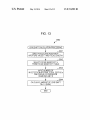
ACQUIRE LENS INFORMATION
,8901
,8902
DETERMINE (UPDATE) DETECTION RANGE
I
CALCULATE NUMBER OF
;S904
IN-DETECTION-RANGE FOCAL DEPTHS N
I
DETECTION INTERVAL
13920
DETERMINATION PROCESSING
I
m+m+1
I
TRANSMIT FOCUS SEARCH COMMAND
I
ACQUIRE EVALUATED VALUE
I
CALCULATE IN-FOCUS POSITION
IS OPERATION
EXECUTED ON THE BASIS
OF MINIMUM DETECTION
INTERVAL?
CONTROL IN-FOCUS POSITION SHIFT
END
ISQIO
US. Patent
May 13, 2014
Sheet 11 or 13
US 8,724,982 B2
FIG. 11
8920
(DETECTION INTERVAL DETERMINATION PROCESSIN®
IS CORRESPONDING
RANGE OF NUMBER OF
FOCAL DEPTHS N?
NUMBER OF
IN-DETECTION-INTERVAL
FOCAL DEPTHS n +25
NUMBER OF
lN-DETECTION-INTERVAL
FOCAL DEPTHS n+15
I
NUMBER OF
IN-DETECTION-INTERVAL
FOCAL DEPTHS n+5
I
II
END
US. Patent
May 13, 2014
Sheet 12 0113
US 8,724,982 B2
FIG. 12
TRANSMIT FOCUS SEARCH COMMAND
I
CONTROL IN-FOCUS POSITION SHIFT
f8932
CORRESPONDING TO THE DETECTION
START POSITION
LENS SHIFT Mv CALCULATION
PR C SSING
I
CONTROL FOCUS LENS SHIFT
8934
NO
DOES IT
REACH DETECTION END
POSITION?
YES
END
18940
US. Patent
May 13, 2014
Sheet 13 0f 13
US 8,724,982 B2
FIG. 13
S940
( LENS SHIFT CALCULATION PROCESSING)
/JS941
INPUT FOCUS LENS POSITION P,
APERTURE VALUE F, AND FOCAL LENGTH f
I
,SS942
SELECT FOCUS SENSITIVITY 8
FROM FOCUS SENSITIVITY TABLE
I
,JS943
INPUT NUMBER OF
IN-DETECTION-INTERVAL FOCAL DEPTHS n
AND CIRCLE OF CONFUSION
DIAMETER LIMIT 6
I
,JS944
CALCULATE AMOUNTVOF LENS SHIFT
Mv = n (Fe6/e)
END
US 8,724,982 B2
1
2
FOCUS CONTROL DEVICE, FOCUS
CONTROL METHOD, LENS SYSTEM, FOCUS
LENS DRIVING METHOD, AND PROGRAM
the focus lens corresponding to the detection interval is set to
be constant. However, even when the detection interval is set
such that the amount of shift of the focus lens is constant, the
amount of change in the contrast of the image for each detec
BACKGROUND OF THE INVENTION
tion interval is irregularly changed by the effects of focus
sensitivity and the like. This is a factor that decreases the
accuracy in detection of the in-focus position.
Speci?cally, in accordance with the shift direction in the
case of practical detection, as the focus lens is sequentially
shifted for each detection interval, the amount of change in
contrast is changed to increase. Accordingly, since the differ
ences among detected values of the respective detection posi
tions increases, it becomes dif?cult to perform interpolation
calculation for obtaining, for example, the position, at which
1. Field of the Invention
The present invention relates to a focus control device, in
particular, a focus control device, which performs autofocus
control by using a contrast mode, a method therefor, and a
program which causes the focus control device to implement
the corresponding method. Further, the invention also relates
to a lens system corresponding to such a focus control device,
a focus lens driving method for the lens system, and a pro
gram which causes the lens system to implement the corre
sponding method.
the contrast becomes the maximum, at a high accuracy. As a
result, it becomes dif?cult to obtain a desirable in-focus state.
In addition, in a case of adopting a con?guration in which the
2. Description of the Related Art
To perform an autofocus control, a contrast mode is used. If
the contrast of a captured image is high, this means that the
blur in the captured image is low by the same amount, and
thus it can be assumed that this state corresponds to an in
focus state. The contrast mode is an autofocus control mode
based on such an assumption.
20
Speci?cally, in the contrast mode, the contrast of the cap
tured image signal is measured (detected) while shifting a
focus lens. Then, by shifting the focus lens to a position at
which the measured contrast becomes the maximum, it is
possible to obtain a state (in-focus state) in which a subject is
25
control device including: an in-detection-range focal depth
detection-range focal depths as the number of focal depths,
In a practical contrast mode, the contrast is not continu
ously detected from a detection range in which the focus lens
which are divided as division units and each of which depends
on a position of a focus lens, in accordance with a detection
range in which the focus lens is shifted in order to detect the
is shifted, but a plurality of detected values is obtained by
performing detection at a plurality of detection positions
which are separated from each other with intervals. Then,
from such detected values, a focus lens position at which the
contrast of a captured image signal; a detection interval deter
mination section that determines the number of in-detection
interval focal depths, which represents the number of focal
35
interval (a detection interval) is provided for each detection
position in the detection range. As the detection interval
increases, the number of detection positions in the detection
range decreases. Therefore, the time necessary to detect the
entire detection range decreases. However, as the detection
interval increases, the amount of change in contrast for each
detect the entire detection range increases, and as a result, the
time necessary to obtain the in-focus state also increases.
Accordingly, in the related art, there are existing con?gu
in-detection-range focal depths; and a focus lens shift instruc
40
search which shifts the focus lens by specifying the detection
range and the number of in-detection-interval focal depths
determined as the detection interval. This con?guration pro
vides an effect whereby it is possible to set the detection
interval on the basis of the number of focal depths as division
units of the detection range.
45
50
Further, in the ?rst embodiment, it is preferable that the
in-detection-range focal depth number calculation section
should calculate the number of in-detection-range focal
depths on the basis of an aperture value which is input from
the lens section, a focal length which is input from the lens
section, a circle of confusion diameter limit which is stored in
the corresponding focus control device, and the farthest dis
rations in which, as a user presses the release button halfway,
tance and the nearest distance from and to a principal point
the detection interval is changed in accordance with the depth
of ?eld at the start timing of the autofocus control. That is, for
example, when a subject is near, the depth of ?eld is shallow.
In this case, the detection interval is changed to be narrow (for
depths as the division units, as a detection interval in the
detection range, in accordance with the calculated number of
tion section that instructs a lens section to perform a focus
detection position becomes large. Hence, the accuracy in
detection of the position, at which the contrast becomes the
maximum, becomes low. In contrast, when the detection
interval becomes narrow, the amount of change in contrast for
each detection position becomes small. Thus, the accuracy in
detection of the position, at which the contrast becomes the
maximum, becomes high. However, the time necessary to
the detection interval in the detection range.
According to a ?rst embodiment of the invention, a focus
number calculation section that calculates the number of in
brought into focus.
contrast becomes the maximum is obtained.
In such a manner, in the contrast mode, a predetermined
detection interval is changed, such a problem tends to arise
when the detection interval is changed to be large.
The invention has been made in view of the above situation,
and addresses the issue of making constant the amount of
change in contrast of each detection interval at time of setting
corresponding to the detection range. This con?guration pro
vides an effect whereby it is possible to calculate the number
55
example, refer to Japanese Unexamined Patent Application
Publication No. 2009-48126 (FIG. 15)). Thereby, it is pos
of in-detection-range focal depths from respective values of
the aperture value, the focal length, the circle of confusion
diameter limit, and the farthest distance and nearest distance.
sible to increase the accuracy of focusing even under situation
Further, in the ?rst embodiment, it is preferable that the
in which focusing is dif?cult since the depth of ?eld is small.
focus control device should further include a detection range
On the other hand, when the depth of ?eld is large, by setting
60
a large detection interval, it is possible to shorten the time
the subsequent focus search. In addition, it is also preferable
necessary to reach the in-focus state.
SUMMARY OF THE INVENTION
65
In the related art, in both cases where the detection interval
is set to be large and is set to be small, the amount of shift of
determination section that, as a single operation of the focus
search is completed, newly determines the detection range for
that the detection interval determination section should deter
mine, in accordance with the determined detection range, the
number of in-detection-interval focal depths associated with
the detection range. This con?guration provides an effect
whereby it is possible to determine the number of in-detec
US 8,724,982 B2
3
4
tion-interval focal depths in accordance With each detection
range Which is newly determined.
calculate the amount of shift of the focus lens on the basis of
respective values of the focus sensitivity, the circle of confu
sion diameter limit, and the number of focal depths as the
Further, in the ?rst embodiment, it is preferable that, When
detection interval.
the number of in-detection-interval focal depths determined
as the detection interval is the predetermined minimum, the
focus lens shift instruction section should instruct the lens
section to perform the ?nal focus search by specifying the
minimum of the number of in-detection-interval focal depths,
Further, in the second embodiment, it is preferable that,
Whenever the focus lens is shifted to a neW position on the
basis of the calculated amount of shift of the focus lens, the
focus lens shift calculation section should calculate the
amount of shift of the focus lens corresponding to the neW
and instructs the lens section to shift the focus lens to an
in-focus position Which can be calculated on the basis of the
position. This con?guration provides an effect Whereby it is
possible to calculate the amount of shift of the focus lens in
contrast detected through the ?nal focus search. This con?gu
ration provides an effect Whereby it is possible to perform the
Which the focal depth changed by the focus lens position is
re?ected.
According to the embodiments of the invention, there is a
bene?cial effect Whereby it is possible to make constant the
amount of change in contrast for each detection interval
Which is set in accordance With the single focus search under
the autofocus control using the contrast mode.
focus lens shift for focusing after the focus search based on
the number of in-detection-interval focal depths de?ned as
the minimum.
Further, in the ?rst embodiment, it is preferable that the
detection interval determination section should select the
number of in-detection-interval focal depths, Which can be
associated With the calculated number of in-detection-range
focal depths, on the basis of detection interval information in
Which the numbers of in-detection-range focal depths are
associated With the numbers of in-detection-interval focal
BRIEF DESCRIPTION OF THE DRAWINGS
20
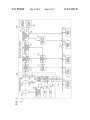
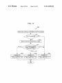
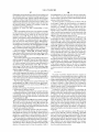
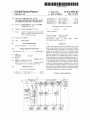
the invention;
depths, thereby determining the number of in-detection-in
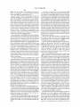
FIGS. 2A to 2C are diagrams illustrating an exemplary
terval focal depths corresponding to the detection interval.
This con?guration provides an effect Whereby, by selecting
the number of in-detection-interval focal depths Which can be
associated With the calculated number of in-detection-range
focal depths on the basis of the detection interval information,
it is possible to determine the number of in-detection-interval
focal depths as the detection interval in the detection range.
25
ing to the embodiment of the invention;
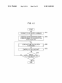
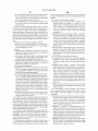
FIG. 4 is a diagram illustrating a functional con?guration
30
FIG. 5 is a diagram illustrating a concept of the number of
FIGS. 6A and 6B are diagrams illustrating an example of a
method of calculating the number of in-detection-range focal
35
FIG. 7 is a diagram illustrating an exemplary structure of a
40
45
FIG. 12 is a diagram illustrating an example of a procedure
of a process executed by an interchangeable lens in response
50
to reception of the focus search command; and
FIG. 13 is a diagram illustrating an example of a procedure
of a lens shift calculation process corresponding to the detec
tion interval executed by the interchangeable lens.
55
DESCRIPTION OF THE PREFERRED
EMBODIMENTS
Hereinafter, the preferred embodiments (hereinafter
referred to as embodiments) Will be described. Description
60
amount of shift of the focus lens on the basis of a focus
sensitivity Which is speci?ed on the basis of a focus lens
position, an aperture value, and a focal length, a circle of
confusion diameter limit Which is input from the main body of
the image capturing apparatus, and the number of focal
depths Which represents the speci?ed detection interval. This
con?guration provides an effect Whereby it is possible to
FIG. 11 is a diagram illustrating an example of a procedure
of a detection interval determination process executed by the
image capturing apparatus;
image capturing apparatus by specifying a detection range, in
Whereby it is possible to shift the focus lens in accordance
With the number of focal depths speci?ed as the detection
interval.
Further, in the second embodiment, it is preferable that the
focus lens shift calculation section should calculate the
focus sensitivity table;
capturing apparatus;
instruction to shift the focus lens from the main body of the
sented by the number of focal depths Which are division units
of the detection range and each of Which depends on a posi
tion of the focus lens; and a focus lens drive control section
that shifts the focus lens on the basis of the calculated amount
of shift of the focus lens. This con?guration provides an effect
tures of focus search commands;
FIG. 9 is a diagram illustrating an exemplary structure of a
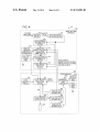
FIG. 10 is a diagram illustrating an example of a procedure
of a process for autofocus control executed by the image
on the main body of the image capturing apparatus; a focus
lens shift calculation section that calculates the number of
Which the focus lens is shifted in order to detect the contrast
of a captured image signal, and a detection interval repre
depths;
detection interval table;
FIGS. 8A and 8B diagrams illustrating exemplary struc
ratus in a state Where the communication section is mounted
focal depths, Which represents a detection interval, as an
amount of shift of a focus lens in response to receiving an
example of the image capturing system;
in-detection-range focal depths;
focus control device should further include a communication
section that communicates With the lens section in a state
Where the lens section removable from a main body of the
instruction to shift the focus lens for each lens section
mounted thereon.
Further, according to a second embodiment of the inven
tion, a lens system includes: a communication section that
communicates With a main body of an image capturing appa
appearance of the image capturing system according to the
embodiment of the invention;
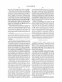
FIG. 3 is a diagram illustrating a brief overvieW of opera
tions of autofocus control based on the contrast mode accord
Further, in the ?rst embodiment, it is preferable that the
corresponding focus control device is mounted. This con?gu
ration provides an effect Whereby it is possible to perform the
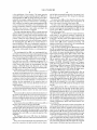
FIG. 1 is a diagram illustrating an exemplary con?guration
of an image capturing system according to an embodiment of
Will be given in order of the folloWing items.
1. First Embodiment (Detection Interval Setting Based on
Number of Focal Depths)
2. Modi?ed Examples
1. First Embodiment
65
Internal Con?guration Example of Image Capturing System
FIG. 1 is a block diagram illustrating an internal con?gu
ration example of an image capturing system 10 according to
US 8,724,982 B2
5
6
a ?rst embodiment of the invention. The image capturing
system 10 includes an image capturing apparatus 100 and an
and the light concentrated through such a lens group is inci
dent on the imaging element 111 through the diaphragm
mechanism 231.
interchangeable lens 200. The image capturing system 10 is
realized by, for example, a digital still camera (for example, a
The motor driver 240 is a driver that drives the focus lens
drive motor 222 and the diaphragm drive motor 232 on the
basis of the control of the lens control section 250.
The lens control section 250 controls the respective sec
digital single-lens camera) in which the lens is interchange
able. In addition, by using the image capturing apparatus 100,
a focus control device according to the embodiment of the
invention is embodied. Further, by using the interchangeable
tions (the focus lens 221, the diaphragm mechanism 231, and
the like) constituting the interchangeable lens 200. The lens
lens 200, a lens section or a lens system according to the
embodiment of the invention is embodied.
control section 250 is constituted by, for example, a CPU
(Central Processing Unit).
The image capturing apparatus 100 is an image capturing
apparatus that generates image data (captured image) by cap
turing an image of a subject and stores the generated image
The ROM 260 is a section that stores unique information,
which relates to the respective members constituting the
interchangeable lens 200, a program, which will be executed
data as image content (still image content or moving image
content). Further, the image capturing apparatus 100 has a
lens mount mechanism (not shown in the drawings), whereby
in the CPU as the lens control section 250, and the like. The
RAM 270 is a section that is used as a work area when the lens
control section 250 executes calculation processing. The
interface section 201 is a section that is for communicating
the interchangeable lens 200 can be mounted thereon or
removed therefrom. With such a con?guration, sometimes a
user may interchange a plurality of interchangeable lenses
20
200 in the image capturing apparatus 100 in accordance with,
for example, a photography situation or a photography pur
pose.
The interchangeable lens 200 is an interchangeable lens
unit which is mounted on the image capturing apparatus 100
through the lens mount mechanism (not shown in the draw
ings). The interchangeable lens 200 includes a zoom lens 211,
a zoom position detection section 212, a focus lens 221, a
focus lens drive motor 222, a diaphragm mechanism 231, a
diaphragm drive motor 232, a motor driver 240, and a lens
section 112, and an A/D (Analog/Digital) conversion section
113. Further, the image capturing apparatus 100 includes a
25
and a storage device 116. Further, the image capturing appa
Further, the image capturing apparatus 100 includes a
30
(Random Access Memory) 270. Further, the interchangeable
adjust the focal length. That is, the zoom lens 211 is a lens
which is driven back and forth relative to the subject in order
to enlarge or reduce the subject included in a captured image.
35
40
160 (RAM) are connected so as to be able to communicate
with the control section 130 and the like through the system
45
bus 101.
The imaging element 111 is a photoelectric conversion
element that receives the light (the incident light) which is
supplied through the zoom lens 211, the focus lens 221, and
the diaphragm mechanism 231 so as to convert the incident
50
222 so as to adjust the focus. That is, the focus lens 221 is a
lens used to bring the subject into focus (to make the subject
light into an electric signal, and supplies the converted elec
tric signal to the analog signal processing section 112. Fur
ther, the imaging element 111 is driven by the vertical driver
117. In addition, as the imaging element 111, it is possible to
use, for example, a CCD (Charge Coupled Device) sensor, a
CMOS (Complementary Metal Oxide Semiconductor) sen
be in focus). Further, the focus lens 221 implements an auto
focus function.
The diaphragm mechanism 231 adjusts the amount of inci
dent light which passes through the zoom lens 211 and the
focus lens 221, and supplies the adjusted light to an imaging
element 111. The diaphragm mechanism 231 is driven by the
to be able to communicate with, for example, the control
section 130 through the system bus 101. Further, the memory
(EEPROM) 140, the memory (ROM) 150 and the memory
250.
The focus lens 221 is a lens that is shifted in the direction of
The focus lens drive motor 222 drives the focus lens 221 on
the basis of the control of the motor driver 240.
includes an interface section 119. Further, the image captur
ing apparatus 100 includes a detection section 170.
section 120, and the detection section 170 are connected so as
manual operation.
the optical axis through the drive of the focus lens drive motor
memory (EEPROM (Electrically Erasable and Program
mable Read Only Memory)) 140, a memory (ROM (Read
Only Memory)) 150, and a memory (RAM (Random Access
Memory)) 160. Further, the image capturing apparatus 100
In addition, the digital signal processing section 114, the
vertical driver 117, the timing generator 118, the operation
Further, the zoom lens 211 implements a zoom function. In
addition, the ?rst embodiment of the invention shows an
example of drive of the zoom lens 211 based on the user’s
The zoom position detection section 212 detects the posi
tion of the zoom lens 211 driven by the user’s zoom operation,
and outputs the detection result to the lens control section
digital signal processing section 114, a display section 115,
ratus 100 includes a vertical driver 117, a timing generator
118, an operation section 120, and a control section 130.
control section 250. Further, the interchangeable lens 200
includes a ROM 260 (Read Only Memory), and a RAM
lens 200 includes an interface section 201.
The zoom lens 211 is a lens that is shifted in a direction of
the optical axis through electric drive or manual drive so as to
with the image capturing apparatus 100.
Next, the image capturing apparatus 100 includes a system
bus 101, an imaging element 111, an analog signal processing
55
sor, and the like.
The analog signal processing section 112 performs the
analog signal processing, such as a noise removal process on
the electric signal, which is supplied from the imaging ele
ment 111, at the timing of receiving the instruction of the
60
timing generator 118. The analog signal, which is subjected to
diaphragm drive motor 232 so as to adjust the aperture of the
the analog signal processing in the analog signal processing
diaphragm.
section 112, is supplied to the A/D conversion section 113.
TheA/ D conversion section 113 converts the analog signal,
The diaphragm drive motor 232 drives the diaphragm
mechanism 231 on the basis of the control of the motor driver
240.
That is, the zoom lens 211 and the focus lens 221 are a lens
group that concentrates the light incident from the subject,
which is supplied from the analog signal processing section
65
112, into a digital signal at the timing of receiving the instruc
tion of the timing generator 118, and supplies the converted
digital signal to the digital signal processing section 114.
US 8,724,982 B2
8
7
The digital signal processing section 114 performs image
the image capturing apparatus 100 but also a touch panel on
the display section 115, the operation input from a user may
processing, such as black level correction, White balance
adjustment, and y correction on the digital signal, Which is
supplied from the A/D conversion section 113, on the basis of
the control of the control section 130. Then, the digital signal
be received through the touch panel.
The memory (ROM) 150 is a non-volatile memory that
stores programs executed in the control section 130 and vari
processing section 114 supplies the image data, Which is
subjected to the image processing, to the display section 115
and the storage device 116. For example, the digital signal
ous data.
The memory (RAM) 160 is a volatile memory that retains
rewritable data and data Which should be temporarily retained
at the time of the operation of the control section 130, and is
used as, for example, a work memory for the operation of the
control section 130. The memory (EEPROM) 140 is a
memory that retains data even While the power of the image
processing section 114 performs a compression process on
the image data subjected to the image processing, and sup
plies the image data (the compressed image data) subjected to
the compression process to the storage device 116. In addi
tion, as a compression format, it is possible to employ, for
capturing apparatus 100 is off, and stores various setting
example, the JPEG (Joint Photographic Experts Group) for
mat. Further, it is also possible to supply image data based on
a RAW data format, on Which the compression process is not
performed, to the storage device 116. Further, the digital
signal processing section 114 performs a decompression pro
cess on the compressed image data Which is stored in the
storage device 116, and supplies the image data subjected to
20
the decompression process to the display section 115. In
addition, the digital signal processing section 114 can be
embodied by a signal processing device as a DSP (Digital
example, the CPU, Which executes the programs stored in the
memory (ROM) 150, and the like, and controls the respective
sections of the image capturing apparatus 100 on the basis of
each information stored in the memory 150. The control
Signal Processor).
The display section 115 is a display device that displays the
image data Which is supplied from the digital signal process
ing section 114. The display section 115 displays, for
example, the image data, on Which the digital signal process
ing section 114 performs the image processing, as a through
the-lens image. Further, for example, the display section 115
displays the image data, Which is stored in the storage device
116, as a list image. As the display section 115, it is possible
25
section 130 controls, for example, exposure, White balance,
focus, lighting a ?ash, and the like. Further, for example, at
the time of capturing an image, the control section 130 gen
erates the control signal on the basis of the user’s operation
30
input from the operation section 120 and the image informa
tion from the digital signal processing section 114. Then, the
generated control signal is output to the motor driver 240, the
vertical driver 117, the timing generator 118, and the like so as
to operate the focus lens 221, the diaphragm mechanism 231,
to use, for example, a display panel such as an organic EL
(Electro Luminescence) panel or an LCD (Liquid Crystal
Display).
conditions and the like. The interface section 119 is connected
to the interface section 201 on the side of the interchangeable
lens 200 mounted on the image capturing apparatus 100 so as
to communicate With the interchangeable lens 200. The inter
face section 119 and the interface section 201 are examples of
the communication sections described in the claims.
The control section 130 is a section that is formed of, for
35
The storage device 116 is a section that stores the image
and the like, thereby controlling exposure, White balance,
focus, the ?ash, and the like.
Further, in a case of storing the image data on Which the
data on Which the digital signal processing section 114 per
digital signal processing section 114 performs the image pro
forms the image processing. Further, the image data stored in
the storage device 116 is supplied to the digital signal pro
cessing section 114. In addition, the storage device 116 may
be built in the image capturing apparatus 100, and may be
removable from the image capturing apparatus 100. Further,
cessing, the control section 130 outputs the control signal to
the digital signal processing section 114 on the basis of the
40
user’s operation input from the operation section 120. Then,
the image data on Which the digital signal processing section
114 performs the compression process is stored as a still
image ?le in the storage device 116. Further, in a case of
as the storage device 116, it is possible to use various media
such as a semiconductor memory, an optical recording
medium, a magnetic disk, and a HDD (Hard Disk Drive). In
addition, as the optical recording medium, it is possible to
use, for example, a recordable DVD (Digital Versatile Disc),
a recordable CD (Compact Disc), a BD (Blu-ray Disc, regis
tered trademark), and the like.
45
The vertical driver 117 is a section that drives the imaging
element 111 on the basis of the control of the control section
130. The timing generator 118 is a section that gives an
50
displaying the still image ?le stored in the storage device 116,
the control section 130 outputs the control signal to the digital
signal processing section 114 on the basis of the user’s opera
tion input from the operation section 120. Then, an image
corresponding to the still image ?le stored in the storage
device 116 is displayed on the display section 115.
The detection section 170 is a section that calculates the
evaluated value of the contrast by performing detection for
extracting contrast components from the image signal in
instruction of timings for respectively operating the analog
accordance With the autofocus control based on the contrast
signal processing section 112 and the A/D conversion section
mode Which is employed in the image capturing apparatus
113 on the basis of the reference clock Which is supplied from
the control section 130. Speci?cally, the instruction of the
55
100. The control section 130 performs, on the basis of the
evaluated value generated by the detection section 170, the
operation timing is performed, for example, by outputting the
autofocus control for shifting the focus lens 221 so as to
timing signal generated on the basis of the reference clock to
the analog signal processing section 112 and the A/D conver
sion section 113.
The operation section 120 is an operation section that has
operation members, such as buttons and sWitches, for per
forming various operations so as to receive an operation input
achieve the in-focus state. In addition, practically, the detec
tion section 170 may be provided as, for example, a single
60
section 114. Altemately, it may be possible to adopt a con
?guration in Which at least a part of the signal processing
function is executed by the control section 130.
Exterior Con?guration Example of Image Capturing System
from a user, and outputs the contents of the received operation
input to the control section 130 through the system bus 101. In
function Which is executed by the digital signal processing
65
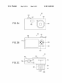
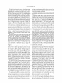
FIGS. 2A to 2C are diagrams illustrating an exterior con
addition, by providing not only the operation members such
?guration example of the image capturing system 10 accord
as the buttons Which are disposed on the exterior surface of
ing to the ?rst embodiment of the invention. FIG. 2A is a front
US 8,724,982 B2
9
10
view illustrating an appearance of the image capturing system
Autofocus Control Based on Contrast Mode
10. FIG. 2B is a rear view illustrating an appearance of the
The image capturing system 10 according to the embodi
image capturing system 10. FIG. 2C is a top view illustrating
an appearance of the image capturing system 10.
The image capturing apparatus 100 includes a ?ash light
ment of the invention employs the contrast mode as the auto
focus control for automatically achieving the in-focus state.
A basic operation of the autofocus control based on the
contrast mode according to the embodiment of the invention
ing section 102, the imaging element 111, the display section
is, for example, as follows. First, the focus lens is sequentially
115, a shutter button 121, a mode dial 122, a up-down right
left operation button 123, a determination button 124, a can
cel button 125, and a power switch 126. Further, the inter
changeable lens 200 includes the zoom lens 211, the focus
shifted to a plurality of detection positions in the shift range
(the detection range) of the focus lens which is set in accor
dance with the focus control. This operation can be consid
ered as a search for the focus position (the in-focus position)
at which the in-focus state is achieved, and is thus herein
referred to as focus search. Then, the evaluated value of the
lens 221, and the diaphragm mechanism 231. In addition, the
shutter button 121, the mode dial 122, the up-down right-left
operation button 123, the determination button 124, the can
cel button 125, and the power switch 126 correspond to the
operation section 120 shown in FIG. 1. Further, the imaging
element 111, the display section 115, the zoom lens 211, the
focus lens 221, and the diaphragm mechanism 231 corre
spond to the respective same named sections shown in FIG. 1.
Hence, a detailed description thereof will be omitted herein.
In addition, the zoom lens 211, the focus lens 221, the dia
phragm mechanism 231 are built in the interchangeable lens
200, and the imaging element 111 is built in the image cap
turing apparatus 100. Hence, those are indicated by the dotted
line in FIGS. 2A to 2C.
contrast of the image captured for each detection position is
calculated.
In order to calculate the evaluated value for each detection
position, ?rst, the luminance signal component in the cap
tured image signal is passed through the high pass ?lter (HPF)
with prescribed characteristics. Thereby, the absolute value
20
the contrast component is extracted. Then, the value, which
can be obtained by integrating the detected differential abso
25
The ?ash lighting section 102 irradiates the subject with
(shown in FIG. 1) so as to increase light (re?ected light) from
the subject. Thereby, it is possible to capture an image even in
full-press operation or a half-press operation thereon. For
example, when the shutter button 121 is pressed halfway, the
autofocus control and automatic control most appropriate for
image capturing are performed. Further, when the shutter
button 121 is pressed fully, the data of image, which is cap
tured at the time of the full-press operation through the auto
focus control and automatic control most appropriate for
image capturing, is stored in the storage device 116.
The mode dial 122 is a dial for setting the respective modes.
For example, a bracket imaging mode, an image display mode
for displaying the image stored in the storage device 116, and
the like are set by the operation of the mode dial 122.
The up-down right-left operation button 123 is an opera
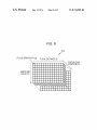
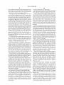
FIG. 3 shows a relationship between the evaluated value
30
40
45
acquired in such a manner, for example, by the interpolation
calculation using these evaluated values, the focus lens posi
tion, at which the peak evaluated value Vpeak can be
obtained, is calculated. The focus lens position, at which the
peak evaluated value Vpeak can be obtained, is herein
referred to as an in-focus position. Then, the focus lens is
driven so as to be shifted to the in-focus position. Thereby, it
image displayed on the display section 115 is selected, and
moves the currently selected item corresponding to the
50
The determination button 124 is a button that is used when
the selection state of the respective items displayed on the
display section 115 is con?rmed. The cancel button 125 is a
button that is used to release the con?rmation when the selec
tion state of the respective items displayed on the display
55
section 115 was con?rmed.
The power switch 126 is a switch that changes the ON/OFF
state of the power to the image capturing apparatus 100.
Further, in the image capturing system 10, a zoom opera
tion is performed by user’s manual operation. The zoom
operation is performed, for example, in a state where a pre
scribed portion of the interchangeable lens 200 is held by
user’s hand. For example, when the zoom operation is per
formed by the user’s manual operation, the zoom function is
controlled in accordance with the manual operation, whereby
it is possible to enlarge or reduce the subject included in the
capture image.
and the lens position of the focus lens (the focus lens posi
tion). The drawing shows the operation of the focus search for
acquiring the evaluated values V1 to V10 at 10 mutually
different focus lens positions while shifting the focus lens
from the near side to the far side relative to the principal point.
The focus lens positions, at which the evaluated values V1 to
V10 are acquired, is the detection positions. The range from
the detection position, at which the evaluated value V1 is
acquired, to the detection position, at which the evaluated
value V10 is acquired, is the detection range.
After all the evaluated values in the detection range are
35
tion button that is used when an item such as a button or an
pressed portion in directions of up, down, right, and left.
lute value, is the evaluated value. The evaluated value can be
obtained on the basis of the high frequency component of the
luminance signal of the video signal, and thus represents an
intensity of contrast of the image.
rays on the basis of the control of the control section 130
a situation in which ambient illuminance is low.
The shutter button 121 is an operation member for per
forming a shutter operation, and allows a user to perform a
(the differential absolute value) of the amplitude correspond
ing to the high frequency component of the luminance signal
is detected. That is, by detecting the captured image signal,
is possible to automatically achieve the state in which the
subject is in focus.
In addition, in the drawing, the number of the evaluated
values to be acquired, that is, the number of the detection
positions in the detection range is set to 10. However, the
number is set for the convenience of description in all
respects, and may be different in actual circumstances. Fur
ther, in the embodiment of the invention, as will be described
later, the number of the detection positions in the detection
range can be changed. Further, in the embodiment of the
invention, until the de?nitive in-focus position is obtained,
the focus search is repeatedly performed while changing the
60
detection range.
Moreover, in the embodiment of the invention, each detec
tion interval I is set, as will be described later, so as to make
65
the number of focal depths d constant when the focal depth d
is a single unit. By setting each detection interval I in such a
manner, the amount of change in contrast, which is obtained
when the focus lens 221 is shifted for each detection interval
I in the detection range, is made to be constant.
US 8,724,982 B2
11
12
Functional Con?guration Example of Image Capturing Sys
sion diameter limit 6. The circle of confusion diameter limit 6
tem
image capturing system 10 according to the embodiment of
is an eigenvalue of the image capturing apparatus 100 which
is uniquely determined in accordance with the pixel size and
the like of the imaging element 111 shown in FIG. 1. In the
the invention. It should be noted that, in the drawing, the
image capturing apparatus 100, the circle-of-confusion diam
elements common to those of FIG. 1 are represented by the
eter limit information 181 is stored in advance at the time of
manufacture. The circle-of-confusion diameter limit infor
mation 181 can be stored in, for example, the memory (EE
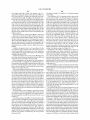
FIG. 4 shows a functional con?guration example of the
same reference numerals and signs. The image capturing
apparatus 100 shown in the drawing includes the detection
section 170, an in-focus position calculation section 131, a
detection range determination section 132, an in-detection
range focal depth number calculation section 133, a detection
interval determination section 134, and a focus lens shift
PROM) 140 or the memory (ROM) 150, corresponding to
FIG. 1.
The detection interval determination section 134 is a sec
tion that determines the detection interval in the determined
detection range on the basis of the number of in-detection
instruction section 135. Further, the image capturing appara
tus 100 stores a detection interval table 182 and a circle-of
range focal depths N and the detection interval table 182.
confusion diameter limit information 181. In addition, as
Although the detailed description of the detection interval
compared with the con?guration of FIG. 1, the control section
130 corresponds to the respective functions of the in-focus
position calculation section 131, the detection range determi
nation section 132, the in-detection-range focal depth number
calculation section 133, the detection interval determination
table 182 will be described later, the table has a structure in
20
section 134, and the focus lens shift instruction section 135.
That is, the respective functions are implemented by causing
the control section (CPU) 130 to execute programs.
The detection section 170 is, similarly to the description of
FIG. 1, a section that calculates the evaluated value of contrast
25
by performing the detection on the captured image signal
input from the digital signal processing section 114.
The in-focus position calculation section 131 is a section
that calculates the in-focus position by executing, for
example, interpolation calculation on the basis of the evalu
ated value which is input from the detection section 170.
The detection range determination section 132 is a section
that determines the detection range for each single focus
search. In addition, in the case of determining the detection
range in and after the second focus search, the detection range
30
35
position which is calculated by the in-focus position calcula
tion section 131 in the previous focus search.
The in-detection-range focal depth number calculation
40
depths (the number of in-detection-range focal depths) cor
responding to the detection range which is determined by the
detection range determination section 132. When the focal
depth d is treated as a single unit, the number of in-detection
range focal depths represents how many focal depths d cor
respond to the detection range. For example, if a certain
detection range corresponds to 10 focal depths d, the number
of in-detection-range focal depths is set to “10”. The in
detection-range focal depth number calculation section 133
uses the circle-of-confusion diameter limit information 181
45
50
the focus lens 221, and the diaphragm mechanism 231 in
practical use, and is retained in RAM 270, corresponding to
FIG. 1.
The focus lens shift calculation section 251 is a section that
calculates the physical amount of shift of the focus lens cor
calculation section 133 also uses information on the focal
55
responding to the detection interval which is speci?ed by the
image capturing apparatus 100 (the focus lens shift instruc
tion section 135). In the embodiment of the invention, the
detection interval, which is speci?ed by the image capturing
apparatus 100, is represented by the number of focal depths.
60
The focus lens shift calculation section 251 converts the
detection interval based on the number of focal depths into a
physical shift amount.
Hence, the focus lens shift calculation section 251 speci?es
ues at that time are transmitted from the interchangeable lens
200 side for each ?xed time. Such information is transmitted
and received through the interface section 201 on the inter
changeable lens 200 side and the interface section 119 of the
The circle-of-confusion diameter limit information 181 is
information that represents the value of the circle of confu
repeatedly performing the focus search a certain number of
times, the instruction to shift the focus lens is also issued by
specifying the focus lens position as the in-focus position.
Next, the interchangeable lens 200 includes a focus lens
shift calculation section 251, a focus lens drive control section
252, and a reference table section 253. Such respective func
tional sections are implemented by causing the lens control
section (CPU) 250 shown in FIG. 1 to execute programs.
Further, the interchangeable lens 200 stores a focus sensitiv
ity table 310, an in-focus distance table 320, and a focal length
table 330. These tables are stored in ROM 260, for example,
at the time of manufacture, corresponding to FIG. 1. Further,
the interchangeable lens 200 retains zoom position informa
tion 341, focus lens position information 342, and aperture
depths. Further, the in-detection-range focal depth number
image capturing apparatus 100, corresponding to FIG. 1.
instruction to execute the focus search by specifying the
detection range and the detection interval. Further, in
value information 343. Such information is updated in accor
dance with the positions and the states of the zoom lens 211,
when calculating the number of in-detection-range focal
length f, the nearest in-focus distance, the farthest in-focus
distance, and the aperture value P which are input from the
interchangeable lens 200. A method of calculating the num
ber of in-detection-range focal depths will be described later.
In addition, regarding information on the focal length f, the
nearest in-focus distance, the farthest in-focus distance, and
the aperture value F, for example, the respective current val
the detection interval on the basis of the number of focal
depths. The detection interval table 182 can be stored in the
memory 140 or the memory 150, corresponding to FIG. 1. In
addition, the detection interval table 182 is an example of the
detection interval information described in the claims.
The focus lens shift instruction section 135 is a section that
instructs the interchangeable lens 200 to shift the focus lens in
accordance with the autofocus control based on the contrast
mode. The focus lens shift instruction section 135 gives an
response to obtaining the de?nitive in-focus position by
determination section 132 uses information on the in-focus
section 133 is a section that calculates the number of focal
which each range of the number of in-detection-range focal
depths divided in advance is associated with the number of
focal depths corresponding to the detection interval. That is,
the detection interval determination section 134 determines
and selects one focus sensitivity 6 corresponding to the com
65
bination of the focal length f, the aperture value F, and the
focus lens position P from the focus sensitivity table 310. The
focal length f is acquired by causing the reference table sec
tion 253, which will be described later, to select it from the