1
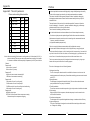
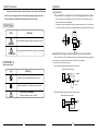
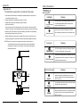
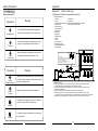
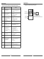
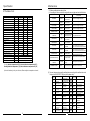
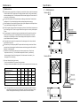
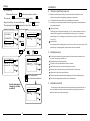
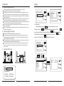
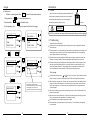
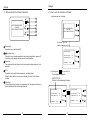
HH Series Air Source Heat Pump
Floor heating and Air-con Unit
Installation and Instruction Manual
Code:2
0110421-0003
1 Preface
2 Safety Precaution
AC-N
AC-N
AC-N
AC-L
COMP1
COMP2
VAL1
VAL2
12V
SYS
GND
GND
GND
FROST
GND
WATER
MDIN
12V
(1) Appendix 1
(2) Appendix 2
(3) Appendix 3
(4) Appendix 4
(5) Appendix 5
(6) Appendix 6
KYIN
(1) Maintenance
(2) Or dinary ma lfunctions and solution
FAN
6 Maintenance
NET
(1) The displaying of the wire controller
(2) How to use the wire controller
GND
5 Usage
CHILLER 300
GND
(1) Application of heat pump
(2) Choose a right heat pump unit
(3) Installation place
(4) Installation method
(5) Water loop connection
(6) Power supply connection
(7) Location of the unit
(8) Transit
(9) Trial Running
5
5
PUMP
4 Installation
2
2
2
3
4
KYOUT
(1) Appearance and Structure of the heat pump
(2) Specification data
(3) Unit Dimension
Appendix 6: Connections code of the main PCB
MDOUT
3 Specification
1
SVAL
(1) Mark notes
(2) Icon Notes
(3) Warning
(4) Attention
7 Appendix
Appendix
CONTENT
INWT
OUTWT
PIPE1
PIPE2
ROOMT
6
7
8
8
9
9
9
10
10
10
11
11
12
12
Connections explanation£
symbol
meaning
No.
SVAL
Electromagnetism 3 way valve£220VAC£
1
PUMP
Water source water pump£220VAC£
2
FAN
3
Fan output£220VAC£
Using side water pump£220VAC£
UPUM
4
VAL1
4way valve of system£220VAC£
5
COMP2
Compressor of system 2£220VAC£
6
COMP1
Compressor of system 1£220VAC£
7
Fire wire
AC-L
8
AC-N
Neutral Wire
9
10 KYOUT GND Switch on/off£high OFF, low ON£
11 MDOUT GND Mode£high cooling, low heating£
12
18
18
19
21
21
22
23
23
24
25
25
No.
12
13
14
15
16
17
18
19
20
21
22
symbol
NET GND 12V
meaning
Remote controller
KYIN GND
On/Off Switch(High OFF, Low ON)
MDIN GND
Mode (High Cooling, Low Heating)
WATER GND
FROST GND
SYS GND 12V
ROOMT
Flow switch protection (Normal close)
Defrost signal
System Protection (Normal close)
Ambient Temp.
PIPE2
Hot water Temp.
PIPE1
Water source Temp.
OUTWT
Using side outlet water Temp.
INTWT
Using side inlet water Temp.
Appendix
Preface
Appendix5: The unit's parameter
Please set according the below table:
Adjust
(yes/no)
In order to provide the customers with high quality, strong reliability and good versatility
product, this heat pump is produced by strict design and manufacture standards.
This manual includes all the necessary information about installation, debugging,
discharging and maintenance. Please read this manual carefully before you open or
maintain the unit.
The manufacture of this product will not be held responsible if someone is injured or
the unit is damaged, as a result of improper installation, debugging, unnecessary
maintenance which is not in line with this manual.
Digit
meaning
default
00
COOL TEMP.
12→
yes
01
HEAT TEMP.
40→
yes
02
DEF. CYC
45M
No use
03
DEF. IN
-7→
No use
04
DEF. OUT
13→
No use
05
DEF. TIME
8M
No use
06
SYSTEM
1/2
yes
¡Maintenance and operation must be carried out according to the recommended time and
frequency, as stated in this manual.
07
SAVE
YES/NO
yes
¡Use genuine standard spare parts only.
08
TYPE
C/H
yes
Failure to comply with these recommendations will invalidate the warranty.
*
PUMP
NORMAL
yes
Air source water chiller and heat pump is a kind of high efficiency, energy saving and
09
The unit must be installed by qualified personnel.
It is vital that the below instructions are adhered to at all times to keep the warranty.
¡The unit can only be opened or repaired by qualified installer or an authorised dealer.
environment friendly equipment, which is mainly used for house warming. It can work with
any kind of indoor unit such fan coil, radiator, or floor heating pipe, by provide warm or hot
Notice: Above data setting 00 is relevant to cooling mode only. All other data (ie 01-08 ) is
relevant to heating.The users can change the parameters according to their needs.
If it is water cooled water chiller heat pump,the parameter (ie 02-05) is not effective.
*Remark:
Parameter 06:
1£the unit has 1 system£
2£the unit has 2 systems¡
water. One unit of monobloc heat pump can also work with several indoor units.
The air source water heat pump unit is designed to have heat recovery by using super
heater which can provide hot water for sanitary purpose.
This series of heat pump unit owns following features:
Parameter 07:
NO£the unit can not restart automatically£
YES£the unit can restart automatically¡
Parameter 08:
C£the mode of the unit is cooling only£
C/H£the mode of the unit is heat pump£
C/H/E£the mode of the unit is auxiliary electrical heating;
H£the mode of the unit is heating only.
Parameter 09:
NORMAL: always open.
SPECIAL: 60 seconds start before compressors starting.
30 seconds stop after compressors stopping.
24
1 Advanced controlling
The PC microcomputer based controller is available for the users to review or set the
running parameters of the heat pump. Centralized controlling system can control several
units by PC.
2 Nice appearance
The heat pump is designed with beautiful looking. The monobloc one has the water
pump included which is very easy for installation.
3 Flexible installation
The unit has smart structure with compact body, just simple outdoor installation is needed.
4 Quiet running
High quality and efficient compressor, fan and water pump is used to ensure the low
noise level with insulation.
5 Good heat exchange rate
The heat pump unit use special designed heat exchanger to enhance whole efficiency.
6 Large working range
This series of heat pump is designed to work under different working conditions as low
as -15 degrees for heating.
1
Appendix
Safety Precaution
To prevent the users and others from the harm of this unit, and avoid damage
on the unit or other property, and use the heat pump properly, please read this
manual carefully and understand the following information correctly.
Appendix 3£
The installation explanation of the leakage pressure valve.
1 The action pressure of leakage pressure valve 'is more than 3bar(valve is open)£
but the pressure can not be adjusted.
Mark Notes
2 The valve will open automatically to make sure that the water loop of air-con system
is safe when the water pressure in the backwater side is higher than the set pressure.
Meaning
Mark
A wrong operation may lead to death or heavy injury on people.
outlet
WARNING
A wrong operation may lead to harm on people or loss of material.
inlet
Appendix 4£The way of assistant heat source connection
ATTENTION
Unit provides the connection of assistant heat source which can not be only for gas-fired
boiler,but also for electronic boiler or warm-net pipe for city accordingly.
Icon notes
The way to the connection is as follows:
1£water chiller and heat pump+assistant gas-fired boiler
Icon
Meaning
water chiller and heat pump
inlet
inlet
Prohibition. What is prohibited will be nearby this icon
outlet
cable
Three-way valve
outlet
control wire
Compulsory implement. The listed action need to be taken.
ATTENTION (include WARNING)
Please pay attention to what is indicated.
gas-fired boiler
2£water chiller and heat pump+assistant electronic boiler
water chiller and heat pump
inlet
inlet
outlet
cable
electronic boiler
outlet
2
23
Appendix
Safety Precaution
Appendix 2£
The installation explanation of automatic filled-water
1
When automatic filled-water valve is installed,the arrowhead orientation of inlet water must
accord with the orientation of valve ;
2 Automatic filled-water has been adjusted in advance to 1.5bar£
3 If readjust the pressure of inlet water,please operate as follows£
* open the screw cap£C££
* If reduce the pressure of water supply,pease unscrew the pressure to adjust the screw(B)£
갛陋품鬧雷慤淃
Warning
Professional installer
is required.
* If increese the pressure of waer supply,please screw down the pressure to adjust the screw (B)
The heat pump must be installed by qualified personals,
to avoid improper installation which can lead to water
leakage, electrical shock or fire.
Please make sure that the unit and power connection
4 When the system need fill water at first,wrest the handle(A) of filled-water.Then the handle(A)
Earthing is required
can return(close) when the system is full of water.
Meaning
Installation
have good earthing, otherwise may cause electrical shock.
5 Automatic filled-water Valve need clean in a periodic time and then you must close the tap,
unscrew the plug(D),remove the inside filter net.Please assemble them again after cleaning.
NOTICE£There are two connections for water pressure meter in the central section of
automatic filled-water,where the water pressure meter can be connected directly
Meaning
Operation
and display the set pressure.The screw cap(C) must be tweaked after adjusting
the filled-water pressure.
DO NOT put fingers or others into the fans and evaporator
B
PROHIBITION
C
of the unit, otherwise harm may be occurred.
When there is something wrong or strange smell, the power
supply need to be shut off to stop the unit. Continue to run
Shut off the power
may cause electrical short or fire.
Move and repair
1/4'
Entrust
1/2'
Meaning
When the heat pump need to be moved or installed again,
please entrust dealer or qualified person to carry it out.
Improper installation will lead to water leakage, electrical
shock, injury or fire.
It is prohibited to repair the unit by the user himself, otherwise
D
Entrust
A
Prohibit
22
electrical shock or fire may be occur.
When the heat pump need to be repaired, please entrust
dealer or qualified person to carry it out. Improper movement
or repair on the unit will lead to water leakage, electrical
shock, injury or fire.
3
Appendix
Safety Precaution
Appendix 1 Install sketch map
갛陋품鬧雷慤淃
ATTENTION
Especial installation(expandable water tank)
Meaning
Installation
The unit CANNOT be installed near the flammable gas.
Installation Place
Once there is any leakage of the gas, fire can be occur.
Make sure that the basement of the heat pump is strong
enough, to avoid any decline or fall down of the unit
Fix the unit
Legend explanation
1 main unit
2 fan coil
3 rubber flexible connection
4 thermometer
5 pressure meter
6 filter similar as "Y"
7 check valve
8 ball valve
9 flow meter
10 bypass valve
11 drain
12 filter
13 two-way valve
14 three-way valve
15 automatic ventilation
16 water pump
17
18
19
20
automatic
fil l- water
valv e
Pressure
le akage
valv e
circuit breaker can lead to electrical shock or fire.
'2/1
Technical request£
1.Each connection must be connected tightly and have no leakage.
2.the arrowhead orientation of automatic filled- water
must accord with water supply.
3.The pressure of automatic filled-water has been
set,and please do not remove screw.
19
1
Meaning
Operation
Please check the installation basement in a period (one month),
to avoid any decline or damage on the basement, which may
hurt people or damage the unit
Please switch off the power for clean or maintenance.
Switch off
the power
Co nnect supply pi pe
16
inlet
outlet
Check the
installation basement
15
17
Make sure that there is circuit breaker for the unit, lack of
Need
circuit breaker
ball valve
ball valve
the close and expandable water tank
automatically filled-water
3
'2/1
1? 20
4 5
7
6
?
10
9
11 drain
14
2
Installation request£
1 The factory only offers main unit (0 and 1)in the legend, and the other modules which are
indispensable fittings, are provided by users or installation company.
2 The unit which of code contains the letter "B" ,has water pump inside and need not install
water pump outside £16£
3 Automatic ventilation£15£is installed on the top point of the water system¡
4 The quantity proportion of two-way valve£13£and three-way valve£14£is referred to the
technical regulation, and there is three-way valve installed on the farthest place of water system.
5 The ball valve (17) is used when it is swashed, filled water in the water system and so on.
It is prohibited to use copper or iron as fuse. The right fuse
must be fixed by electrician for the heat pump.
Prohibition
It is prohibited to spray the flammable gas to the heat pump,
as it may cause fire.
Prohibition
4
13
12
21
Specification
Maintenance
3)¡Look over and clear the failure according to below information.
Failure
Heat pump
cannot
be started
Water pump is
running with
high noise or
without water
Heat pump
capacity is low,
compressor
do not stop
High compressor
exhaust
Solutions
Possible causes for the failure
1 Wrong power supply
2 power supply cable loose
3 circuit breaker open
1 shut off the power and check power supply;
2 check power cable and make right connection
3 check for the cause and replace the fuse or
circuit breaker
1
2
3
4
1 check the water supply and charge water
to the piping;
2 discharge the air in the water loop;
3 open the valves in water loop;
4 clean the water filter.
lack of water in the piping
much air in the water loop
water vavles closed
dirt and block on the water filter
1 Appearance and structure of the unit£
1 lack of refrigerant;
2 bad insulation on water pipe;
3 low heat exchange rate on air side
exchanger;
4 lack of water flow
1 too much refrigerant
2 low heat exchange rate on air side
exchanger
1 check for the gas leakage and recharge the
refrigerant;
2 make good insulation on water pipe;
3 clean the air side heat exchanger;
4 clean the water filter
1 lack of gas
2 block on filter or capillary
1 check the gas leakage and recharge freon;
2 replace filter or capillary;
1
2
3
4
5
6
1
2
3
4
5
6
Circulating fan
(side discharge)
Wire
controller
The maximum cable for the wire
controller is 200 metres from the heat pump.
Water inlet
Water outlet
1 discharge the redundant gas
2 clean the air side heat exchanger
Low pressure
problem
of the system
Compressor do
not run
High noise of
compressor
Fan do not run
power supply failure
compressor contactor broken
power cable loose
protection on compressor
wrong setting on return water temp.
lack of water flow
1 liquid refrigerant goes into compressor
2 compressor failure
1 bad evaporation, check the cause for bad
evaporation and get rid of this;
2 use new compressor;
1 failure on fan relay
2 fan motor broken
1 replace the fan relay;
2 replace fan motor.
1 no gas in the heat pump;
2 heat exchanger broken;
3 compressor failure.
1 check system leakage and recharge refrigerant;
2 find out the cause and replace the heat
exchanger;
3 replace compressor.
1 low water flow rate;
2 low setting for the desired water temp.;
1 clean the water filter and discharge the air in
water loop.
2 reset the desired water temperature.
1 lack of water in the system;
2 failure on flow switch
1 clean the water filter and discharge the air in
water loop.
2 replace the flow switch.
The compressor
runs but heat
pump has not
check off the power supply;
replace compressor contactor;
tighten the power cable;
check the compressor exhaust temp.;
reset the return water temp.;
clean the water filter and discharge the air in
water loop.
heating or
cooling capacity
Low outlet water
temperature
Low water flow
protection
20
5
Maintenance
Specification
2. Ordinary malfunctions and solution
(1) According to failure code of the controller,we can judge and solute the failure.
2. The data of unit
Malfunction
Unit Model
Cooling Capacity
kW
Btu/h
Heating capacity
kW
Btu/h
HH13
HH17
HH251
10.0
13.5
19.5
34000
46000
67000
13.0
17.0
25.0
44000
60000
85000
Cooling Power Input
kW
3.5
4.7
7.0
Heating Power Input
kW
3.1
4.1
6.0
Running Current(Cooling/Heating)
A
15.2/13.5
20.4/17.8
12.1/10.3
230V~/50Hz
230V~/50Hz
380V/3N~/50Hz
2
2
3
Compressor
Rotary
Rotary
Rotary
Fan Quantity
2
2
2
Power Supply
Compressor Quantity
Fan Power Input
W
120¡2
120¡2
200¡2
Fan rotate speed
RPM
850
850
750
Noise
dB(A)
56
56
59
Hot water volume
L/h
40
57
57
Water Pump Input
kW
0.2
0.2
0.75
Water head
m
10
10
24
Water Connection
inch
1
1
1.5
Water Flow Volume
m 3/h
1.7
2.8
3.8
34
34
36
Water Pressure Drop
kPa
Unit Net Dimensions(L/W/H)
mm
See the drawing of the units
see package label
Unit Shipping Dimensions(L/W/H)
mm
Net Weight
kg
see nameplate
Shipping Weight
kg
see package label
Cooling: Ambient temperature:35¡/24¡,Inter/outlet water temperature:12¡/7¡
Heating: Ambient temperature:7¡/6¡,Inter/outlet water temperature:30¡/35¡
(Above information just for your reference, Please subject to nameplate on the unit)
WATER IN
1 Flash
WATER OUT
2 Flash
PIPE TEMP.1
3 Flash
PIPE TEMP.2
4 Flash
AMBIENT TEMP.
5 Flash
The sensor is open
or short circuit
The sensor is open
or short circuit
The sensor is open
or short circuit
The sensor is open
or short circuit
The sensor is open
or short circuit
Water flow volume not
enough,water pressure
difference is too low
Resolution
Check or change the sensor
Check or change the sensor
Check or change the sensor
Check or change the sensor
Check or change the sensor
Check the water flow volume,
or system obstruction.
TEMP. DIFFERENCE
PROTECT
light
FROSTBITE 1
light
FROSTBITE 2
light
SYSTEM 1
6 Flash
System1 protection
was failed
SYSTEM 2
7 Flash
System2 protection
was failed
WATER FLOW
8 Flash
No water/little water
in water system.
POWER PHASE
(SYSTEM PROTECT)
9 Flash
Wrong connections or
lack of connection
Check connections of power cable
TEMP. DIFFERENCE
ERROR
10 Flash
Water flow rate not
enough
Check the water flow rate, or
water system is jammed or not
COMMUNICATION
Flash
Ambient or inlet water
temp. is too low
Ambient or inlet water
temp. is too lower
Chec k eac h pr ot ec tion poi nt of sy st em1
remove the mal func tion ac co rdi ng to
Sys tem Pr ot ec tion Boar d mal func tion tabl e)
Ch ec k ea ch pr ot ec tion po int of system2
remo ve the mal fun ction ac cor di ng to
Sy stem Pr ot ec tion Bo ar d mal fun ction tab le)
Check the water flow volume,
water pump is failure or not
Wire controller and The Check the wire connection
PCB connection failure
(2) You can judge and remove the malfunctions according to the malfunction code
display on the PROTECT 300(only for 3 phase units)
Display
Name
reason
Action
Recover
(yes or no)
revolution
3
Unit stops
Co oling wa ter temp .
Co oling wa ter freezing
too low af ter tube ou tlet and alarm
Cooling water temp. Unit stops
Cooling water
after tube inlet
and alarm
antifreezing failure
too low
Low pressure
Unit stops
Low pressure
switch action
and alarm
4
Compressor exhaust
temp. too high
5
Over-current
on compressor
Compressor exhaust
temp.too high
Current through
compressor too heavy
6
High pressure
High pressure
switch action
7
Temp. sensor before Temp. Sensor open
tube failure
or short circuit
Unit stops
and alarm
Yes
Check and renew
the sensor
8
Tube outlet temp.
sensor failure
Temp. Sensor open
or short circuit
Unit stops
and alarm
Yes
Check and renew
the sensor
Exhaust temp.
sensor failure
Power supply
wrong connection
Temp. Sensor open
or short circuit
Unit stops
and alarm
Yes
Check and renew
the sensor
Wrong connection
or lack of connection
Unit stops
and alarm
Yes
Check the connections
1
2
9
E
6
Reason
Running lamp
19
Unit stops
and alarm
Unit stops
and alarm
Unit stops
and alarm
Yes
Yes
Yes
Yes
Yes
Yes
Check water flow volume
Check the water system
Check through the
pressure switch
and return system
Check through the
refrigerant system
Check through the power
supply for compressor
or short circuit
Check through the
pressure switch
and return system
Maintenance
Specification
1 ¡ Maintenance
3
Check the water supply and air vent frequently, to avoid lack of water or air in the water loop.
Clean the water filter in a certain period to keep good water quality. Lack of water and dirty
water can damage the unit. The heat pump will start the water pump per 72 hours when it is
not running, to avoid freezing.
Keep the unit in a place which is dry and clean, and has good ventilation. Clean the heat
exchanger in 1 or 2 month and keep good heat exchange rate and save energy.
Unit dimension
Models:HH13
HH17
Check each part of the unit and the pressure of the system. Replace the failure part if there
is any, and recharge the refrigerant if it is needed.
Check the power supply and the electrical system, make sure the electrical components are
good, the wiring is well. If there is any part failed with wrong action or smell, please replace
in time.
If the heat pump is not used for a long time, please drain out all the water in the unit and
seal the unit to keep it good. Please drain the water from the lowest point of the heat
exchanger to avoid freezing in winter. Water recharge and full inspection on the heat
pump is needed before it is restarted.
Water outlet
Super heater access
Water inlet
Please drain out the water in the super heater of the heat pump unit in winter, when the
super heater is not used.
The water loop of the heat pump MUST be protected from freezing in winter time.Please
pay attention to below suggestions.Nonobservance on below suggestion will invalid the
warranty for the heat pump.
(1) Please do not shut off the power supply to the heat pump in winter. When the air
temperature is below 0 ¡, if the inlet water temperature is above 2 ¡ and below 4¡,
the water pump will start for freezing protect, if the inlet water is lower than 2 ¡, the
heat pump will run for heating.
Drainage
Models:HH251
Glycol percentage £%£
ambient temp. (¡)
cooling/heating capacity fluctuation
20
10
30
40
50
-3
-8
-14
-22
-33
0.991
0.982
0.972
0.961
0.946
power input fluctuation
0.996
0.992
0.986
0.976
0.966
water flow fluctuation
1.013
1.040
1.074
1.121
1.178
water drop fluctuation
1.070
1.129
1.181
1.263
1.308
1450
(2) Use anti-freezing liquid (glycol water)
1) look for below table for the volume of the glycol water
2) the glycol water can be added into the system from the expansion tank of the water loop.
Water inlet
Water outlet
Drainage
Note: if the glycol water is too much, the water flow and water pump will be influenced
and the heat exchange rate will be decreased. This table is for reference, please
use anti-freezing water according to the real condition of the local climate.
515
485
Super heater access
820
1350
18
7
Usage
Installation
e) Time setting
2
When standby, press¡
Then, press¡
Prg¡key to enter into menu surface.
¡ to select time setting mode and the¡
begin time setting. You can use this key¡
confirm it and use ¡
¡key to
¡ again to
DATE
CLOCK
TIMER ON
TIMER OFF
Prg
24/03/2011
16:02
08:00
22:30
pump features as below:
Heating and Cooling unit £ for cooling chilled water outlet temp. at 5-15 ¡ ,maximum
ambient temp. at 43 ¡ . For heating, warm water inlet temp. at 40-50 ¡ , minimum ambient
Prg
temp. at -10 ¡ .
Esc
Air source water chiller and heat pump is used for house, office, hotel, and so forth, which
Unit application
Esc
Esc
2.2 Conclude the total capacity which will be needed by the construction.
2.3 According to the total capacity needed, choose the right model by consulting the heat.
Cooling only unit£ chilled water outlet temp. at 5-15 ¡ , maximum ambient temp. at 43 ¡ .
TIME
TEMP CURVE
calculate the required cooling(heating) capacity per square meter.
Heat pump features
¡to back to submenu.
MAIN MENU
PARAMETER
2.1 Based on the local climate condition, construction features and insulation level,
¡to change parameter.
The same way for modify
Esctime parameter. Press this ¡
Choose a right heat pump unit
need heating or cooling separately, with each area need to be controlled.
Esc
Esc
3 Installation place
The unit can be installed on any place outdoor which can carry heavy machine such
as terrace, housetop, ground and so on.
DATE
CLOCK
TIMER ON
TIMER OFF
24/03/2011
16:02
08:00
22:30
DATE
CLOCK
TIMER ON
TIMER OFF
Prg
24/03/2011
16:02
08:00
22:30
The location must have good ventilation.
Prg
The place is free from heat radiation and other fire flame.
A pall is needed in winter to protect the heat pump from snow.
Esc
Esc
There must be not obstacles near the air inlet and outlet of the heat pump.
A place which is free from strong air blowing.
keys to change data
key choose the modified data
There must be water channel around the heat pump to drain the condensing water .
There must be enough space around the unit for maintenance.
4 Installation method
Use the same way to
change clock, timer
on and off.
The heat pump can be installed onto the concrete basement by expansion screws, or
DATE
CLOCK
TIMER ON
TIMER OFF
24/03/2011
16:02
08:00
22:30
onto a steel frame with rubber feet which can be placed on the ground or housetop.
Prg
Make sure that the unit is placed horizontally.
Esc
16
9
Usage
Installation
5 Water loop connection
Please pay attention to below matters when the water pipe is connected:
Try to reduce the resistance to the water from the piping.
The piping must be clear and free from dirty and blocks. Water leakage test must be
carried out to ensure there is no water leaking. And then the insulation can be made.
Attention that the pipe must be tested by pressure separately. DO NOT test it together
with the heat pump.
There must be expansion tank on the top point of the water loop, and the water level in
the tank must be at least 0.5 meter higher than the top point of the water loop.
The flow switch is installed inside of the heat pump, check to ensure that the wiring and
action of the switch is normal and controlled by the controller.
Try to avoid air stayed inside of the water pipe, and there must be air vent on the top
point of the water loop.
There must be thermometer and pressure meter at the water inlet and outlet, for easy
inspection during running.
6 Power supply connection
If an additional auxiliary heater is need to be controlled by the heat pump controller,
the relay (or power) of the aux-heater must be connected to the relevant output of
the controller.
7 Location of the unit
Esc
Inlet water
Outlet water
ATTENTION
D
Esc
d) Parameter
When standby, press¡
Prg ¡key to enter into menu surface.
¡key to select parameter setting and the¡
Then, press the¡
¡
¡to change parameter.
And the same way for modify
Esctime parameter. Press this ¡
¡ again to
¡key to back to submenu.
confirm it and use the¡
MAIN MENU
PARAMETER
Prg
TIME
Esc
Esc
Maintenance
space
COOL TEMP
HEAT TEMP
DEF.CYC
DEF.IN
DEF.OUT
DEF.TIME
SYSTEM
SAVE
12¡
40¡
45M
-7¡
13¡
8M
4
YES
TYPE
C/H/E
PUMP
NORMAL
Prg
Prg
Esc
Esc
Requirement:
A>500mm; B>1500mm;
C>1000mm;D>500mm。
10
Prg
wall
wall
C
wall
Prg
TEMP CURVE
B
Air outlet
wall
Air inlet
UNIT STATUS
WATER IN
17→
WATER OUT
50→
PIPE 1
10→
PIPE 2
15→
AMBIENT TEMP 15→
key to begin setting. You can use this key¡
Open the front panel, and open the power supply access.
The power supply must go through the wire access and be connected to the power
supply terminals in the controlling box. Then connect the 3-signal wire plugs of the
wire controller and main controller.
If the outside water pump is needed, please insert the power supply wire into the wire
access also and connect to the water pump terminals.
A
MODE SELECT
15
Usage
Installation
8 Transit
c) Main menu
When it is running,press the¡
Prg¡key to enter into menu surface£
When the unit need to be hung up during installation, a 8
meters cable is needed, and there must be soft material
Then press the¡
¡key to enter into main menu
between the cable and the unit to prevent damage to
And press the ¡
¡key to enter the next menu.
Esc
At last,pressing the ¡
¡key can come back to the front page.
the heat pump cabinet. (See picture 1)
Picture 1
WARNING
DO NOT touch the heat exchanger of the heat pump with fingers or other objects£
MAIN MENU
PARAMETER
TIME
TEMP CURVE
MAIN MENU
PARAMETER
Prg
Prg
TIME
Inspection before trial running
TEMP CURVE
Esc
9 Trial Running
Esc
Esc
Check the indoor unit, and make sure that the pipe connection is right and the relevant
valves are open .
Check the water loop, to ensure that the water inside of the expansion tank is enough, the
water supply is good, the water loop is full of water and without any air. Also make sure
there is good insulation for the water pipe.
Check the electrical wiring. Make sure that the power voltage is normal, the screws are
fastened, the wiring is made in line with the diagram, and the earthing is connected.
MODE SELECT
UNIT STATUS
COOL/HEAT
Prg
Esc
Esc
HEAT
AUX HEATING OFF Prg
Esc
Check the heat pump unit including all of the screws and parts of the heat pump to see if
they are in good order. When power on, review the indicator on the controller to see if
there is any failure indication. The gas gauge can be connected to the check valve to
see the high pressure(or low pressure) of the system during trial running.
Trial running
Start the heat pump by press "
or
" key on the controller. Check whether the water
pump is running, if it runs normally there will be 0.2 MPa on the water pressure meter.
"Aux heating ON" means that
the system has the output of aux heating;
"Aux heating OFF" means that
the system has the output of aux heating;
MODE SELECT
UNIT STATUS
When the water pump runs for 1 minutes, the compressor will start. Hear whether there is
strange sound from the compressor. If abnormal sound occurs please stop the unit and
check the compressor. If the compressor runs well please look for the pressure meter
of the refrigerant.
Prg
Then check whether the power input and running current is in line with the manual. If not
please stop and check.
Esc
Adjust the valves on the water loop, to make sure that the hot(cool) water supply to each
door is good and meet the requirement of heating(or cooling).
Review whether the outlet water temperature is stable.
The parameters of the controller are set by the factory, it is not allowed to change then
by user himself.
14
11
Usage
Usage
1) Wire controller functions instruction
2) How to use the remote controller£
a) when power on, it shows:
1
2
AIR COOLED WATER
CHILLER
HEAT PUMP CONTROL
Prg
Esc
3
4
5
6
AIR COOLED WATER
CHILLER
HEAT PUMP CONTROL
Prg
Esc
10 seconds latter, the
standby interface occurs.
1 Switch Key
Press this key to switch on/off£
STATUS:Standby
2 4 Up/down Key
Inlet water temp.
Outlet water temp.
Press this key to read parameters in any state in standby or power off.
Press this key to change the parameter in setting state.
3 Menu Key
You can press this key to enter into menu surface when power on or in
standby.
5 Exit
Press this key to confirm the parameter in setting state.
When in other states, you can press this key to return to the former
surface.
6 Enter Key
Press up/down key to enter into parameter roll, then press enter key to
go into parameter list and change the data.
16/02/2011
15:3?
Prg
Esc
b) After press"
",the unit will run.
The display is as follows£
UNIT STATUS£
Defrost-Cooling-Heating-Standby
Press
STATUS:Standby
Inlet water temp.
Outlet water temp.
16/02/2011
12
20¡
30¡
15:3?
20¡
30¡
"
"
STATUS:Heating
Prg
Inlet water temp.
Outlet water temp.
Esc
16/02/2011
13
15:3?
20¡
30¡
Prg
Esc