1
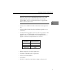
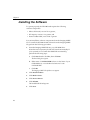
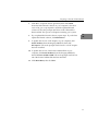
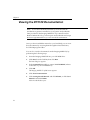
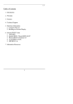
UM-18113- E DT3120 Getting Started Manual Fifth Edition August, 2002 Copyright © 2001 to 2003 by Data Translation, Inc. All rights reserved. Information furnished by Data Translation, Inc. is believed to be accurate and reliable; however, no responsibility is assumed by Data Translation, Inc. for its use; nor for any infringements of patents or other rights of third parties which may result from its use. No license is granted by implication or otherwise under any patent rights of Data Translation, Inc. Use, duplication, or disclosure by the United States Government is subject to restrictions as set forth in subparagraph (c)(1)(ii) of the Rights in Technical Data and Computer software clause at 48 C.F.R, 252.227-7013, or in subparagraph (c)(2) of the Commercial computer Software Registered Rights clause at 48 C.F.R., 52-227-19 as applicable. Data Translation, Inc., 100 Locke Drive, Marlboro, MA 01752 Data Translation, Inc. 100 Locke Drive Marlboro, MA 01752-1192 (508) 481-3700 www.datatranslation.com Fax: (508) 481-8620 E-mail: [email protected] Data Translation and GLOBAL LAB are registered trademarks, and Imaging OMNI CD, DT-Open Layers, Frame Grabber SDK, DT Vision Foundry, Sci-Pak, and GLI/2 Streamline are trademarks of Data Translation, Inc. All other brand and product names are trademarks or registered trademarks of their respective companies. Table of Contents About this Manual . . . . . . . . . . . . . . . . . . . . . . . . . . . . . . . . . . v Intended Audience. . . . . . . . . . . . . . . . . . . . . . . . . . . . . . . . . . . . . . . v What You Should Learn from this Manual. . . . . . . . . . . . . . . . . . . v Conventions Used in this Manual . . . . . . . . . . . . . . . . . . . . . . . . . vi Related Information . . . . . . . . . . . . . . . . . . . . . . . . . . . . . . . . . . . . . vi Where to Get Help . . . . . . . . . . . . . . . . . . . . . . . . . . . . . . . . . . . . . . vii Chapter 1: Overview . . . . . . . . . . . . . . . . . . . . . . . . . . . . . . . . 1 Key Hardware Features . . . . . . . . . . . . . . . . . . . . . . . . . . . . . . . . . . . 2 DT3120 Software. . . . . . . . . . . . . . . . . . . . . . . . . . . . . . . . . . . . . . . . . 3 Getting Started Procedure . . . . . . . . . . . . . . . . . . . . . . . . . . . . . . . . . 4 Chapter 2: Preparing to Use the DT3120 Board . . . . . . . . . . 5 Unpacking . . . . . . . . . . . . . . . . . . . . . . . . . . . . . . . . . . . . . . . . . . . . . . 7 Checking the System Requirements . . . . . . . . . . . . . . . . . . . . . . . . 8 Installing the Software. . . . . . . . . . . . . . . . . . . . . . . . . . . . . . . . . . . 10 Viewing the DT3120 Documentation . . . . . . . . . . . . . . . . . . . . . . 12 Chapter 3: Installing the Board and Configuring the Device Driver . . . . . . . . . . . . . . . . . . . . . . . . . . . . . . . . . . . . . 15 Installing the Board . . . . . . . . . . . . . . . . . . . . . . . . . . . . . . . . . . . . . 17 Setting up the Computer . . . . . . . . . . . . . . . . . . . . . . . . . . . . . 17 Selecting an Expansion Slot . . . . . . . . . . . . . . . . . . . . . . . . . . . 18 Inserting the DT3120 Board in the Computer . . . . . . . . . . . . 18 Loading and Configuring the Device Driver . . . . . . . . . . . . . . . . 21 Loading the Device Driver (Windows XP Only) . . . . . . . . . 21 Configuring the Device Driver . . . . . . . . . . . . . . . . . . . . . . . . 22 iii Contents Chapter 4: Connecting Signals . . . . . . . . . . . . . . . . . . . . . . 23 Connecting Video Signals to the Board. . . . . . . . . . . . . . . . . . . . . 25 Connecting an External Trigger to the Board . . . . . . . . . . . . . . . . 27 Chapter 5: Verifying Board Operation . . . . . . . . . . . . . . . . . 29 Installing DT-Acquire . . . . . . . . . . . . . . . . . . . . . . . . . . . . . . . . . . . 32 Using DT-Acquire. . . . . . . . . . . . . . . . . . . . . . . . . . . . . . . . . . . . . . . 33 Synchronously Acquiring a Single Frame to Memory . . . . 34 Performing a Passthru Operation . . . . . . . . . . . . . . . . . . . . . . 35 Index . . . . . . . . . . . . . . . . . . . . . . . . . . . . . . . . . . . . . . . . . . . . . 37 iv About this Manual This manual describes how to get started using a DT3120 frame grabber board. Intended Audience This document is intended for engineers, scientists, technicians, or others responsible for setting up a DT3120 board to perform machine vision and/or image analysis operations. It is assumed that you have some familiarity with the operating characteristics of your video source. It is also assumed that you are familiar with the Microsoft Windows 98, Windows Me (Millennium Edition), Windows 2000, or Windows XP operating system. What You Should Learn from this Manual This manual will help you install and set up your board and device driver successfully. It is organized as follows: • Chapter 1, “Overview,” describes the key features of the DT3120 hardware and software, and provides an overview of the getting started procedure; • Chapter 2, “Preparing to Use the DT3120 Board,” describes how to unpack the board and software, check system requirements, install the DT3120 software, and view the DT3120 documentation online; • Chapter 3, “Installing the Board and Configuring the Device Driver,” describes how to install DT3120 boards and configure the device driver; • Chapter 4, “Connecting Signals,” describes how to connect signals to the board; v About this Manual • Chapter 5, “Verifying Board Operation,” describes how to verify the board’s operation using DT-Acquire. • An index completes this manual. Conventions Used in this Manual The following conventions are used in this manual: • Notes provide useful information that requires special emphasis, cautions provide information to help you avoid losing data or damaging your equipment, and warnings provide information to help you avoid catastrophic damage to yourself or your equipment. • Items that you select or type are shown in bold. • Courier font is used to represent source code. Related Information Refer to the following documents for more information on using an DT3120 board: • The DT3120 User’s Manual (UM-18109), included on the Imaging OMNI CD provided with the DT3120 board, describes the features of the DT3120 board and DT3120 Device Driver. • Frame Grabber SDK User’s Manual (UM-15943) and the Frame Grabber SDK online help, included on the Imaging OMNI CD, describe the Dynamic Linkable Library (DLL) that you can use to write image acquisition application software. • DT-Active Open Layers User’s Manual (UM-17325), available from Data Translation, describes DT-Active Open Layers, an ActiveX control, which allows you to use Data Translation PCI frame grabber boards within graphical programming environments such as Microsoft Visual Basic® and Visual C++®. vi About this Manual • GLOBAL LAB Image/2 User’s Manual (UM-17790), available from Data Translation, describes how to use GLI/2 and GLI/2 • Streamline to create scientific applications using object-oriented image processing tools. • GLOBAL LAB Image/2 API Manual (UM-17792), available from Data Translation, describes how to develop custom tools for GLI/2 using the API. • DT Vision Foundry User’s Manual (UM-17755) and DT Vision Foundry API Manual (UM-17757), available from Data Translation, describe how to use DT Vision Foundry to create machine vision applications using object-oriented image processing tools. Where to Get Help Should you run into problems installing or using a DT3120 board, our Technical Support Department is available to provide technical assistance. Refer to the Troubleshooting chapter of the DT3120 User’s Manual for more information (see page 12 for information on viewing this manual). If you are outside the United States or Canada, call your local distributor, whose number is listed in your Data Translation product handbook. vii About this Manual viii 1 Overview Key Hardware Features . . . . . . . . . . . . . . . . . . . . . . . . . . . . . . . . . . . 2 DT3120 Software. . . . . . . . . . . . . . . . . . . . . . . . . . . . . . . . . . . . . . . . . 3 Getting Started Procedure . . . . . . . . . . . . . . . . . . . . . . . . . . . . . . . . . 4 1 Chapter 1 Key Hardware Features The DT3120 frame grabber is a half-sized board that supports the following key hardware features: • One monochrome or composite (NTSC/RS-170 or PAL/CCIR video format) color input, or one S-video input (Y/C video format). • One external trigger input. Refer to the DT3120 User’s Manual for more information on the hardware. See page 12 for information on viewing this manual. 2 Overview DT3120 Software The DT3120 software, provided on the Imaging OMNI CD shipped with the board, includes the following components: • DT3120 Device Driver − This software must be installed and loaded before you can use a DT3120 board with any of the supported software packages or utilities. • DT3120 User’s Manual, in PDF format − Describes the features of the DT3120 board and how to use the DT3120 Device Driver with the Frame Grabber SDK to write an application program. 1 1 1 • This manual in PDF format. Refer to Chapter 2 starting on page 5 for information on installing the DT3120 software. 1 1 1 1 1 1 3 Chapter 1 Getting Started Procedure The flow diagram shown in Figure 1 illustrates the steps needed to get started using the DT3120 board. This diagram is repeated in each chapter; the shaded area in the diagram shows you where you are in the getting started procedure. Prepare to Use the DT3120 Board (see Chapter 2) Install the Board and Configure the Device Driver (see Chapter 3 starting on page 15) Connecting Signals to the Board (see Chapter 4 starting on page 23) Verify Board Operation (see Chapter 5 starting on page 29) Figure 1: Getting Started Flow Diagram 4 2 Preparing to Use the DT3120 Board Unpacking . . . . . . . . . . . . . . . . . . . . . . . . . . . . . . . . . . . . . . . . . . . . . . 7 Checking the System Requirements . . . . . . . . . . . . . . . . . . . . . . . . 8 Installing the Software. . . . . . . . . . . . . . . . . . . . . . . . . . . . . . . . . . . 10 Viewing the DT3120 Documentation . . . . . . . . . . . . . . . . . . . . . . 12 5 Chapter 2 Prepare to Use the DT3120 Board (this chapter Install the Board and Configure the Device Driver (see Chapter 3 starting on page 15) Connecting Signals to the Board (see Chapter 4 starting on page 23) Verify Board Operation (see Chapter 5 starting on page 29) 6 Preparing to Use the DT3120 Board Unpacking Open the shipping box and verify that the following items are present: • DT3120 frame grabber board, and • Imaging OMNI CD. CAUTION: Keep the DT3120 board in its protective antistatic bag until you are ready to install it. If an item is missing or damaged, call Data Translation's Customer Service Department at (508) 481-3700. Customer Service will guide you through the appropriate steps for replacing missing or damaged items. If you are located outside the United States, call your local distributor, listed in your Data Translation Product Handbook. 2 2 2 2 2 2 Note: It is recommended that you save the original packing material in the unlikely event that your board requires servicing in the future. 2 2 2 7 Chapter 2 Checking the System Requirements For reliable operation, your DT3120 board requires the following minimum system requirements: • 133 MHz Pentium processor with an Intel PCI chip set that supports and enables PCI-to-posted memory writes; Pentium II recommended. The following Intel PCI chip sets are known to work properly: − Triton 8243xFX, − Triton2 8243xHX, − Triton VX 8243xVX, − Triton TX 8243xTX, − Natoma 8244xFX, or − Natoma 8244xLX. Note: The following Intel PCI chip sets are known not to work properly: Saturn 8242x, Mercury 8243xLX, Neptune 8243xNX, Orion 8245xKX, and Orion 8245xKG. If your system contains one of these chip sets, call your system manufacturer to replace the chip set with one that is supported. • A BIOS that complies with PCI specifications, such as one of the following: − AMI, or − AWARD (version 4.51PG). 8 Preparing to Use the DT3120 Board Note: Version 4, revision 6 of the Phoenix BIOS works properly. However, early versions of this BIOS are known not to work properly. If your system contains an earlier version of the Phoenix BIOS, call your system manufacturer to upgrade the BIOS to Version 4, revision 6. • At least one available PCI 32-bit or 64-bit bus master expansion slot. • At least 32 MB of RAM. Note that 864 KB are required to store each frame. • A 2 MB, 32-bit PCI graphics card with a 256 color palette for 640 x 480 32-bit true color RGB display. A DDI-compatible PCI graphics card is recommended for real-time display. The PCI graphics card memory requirements are as follows: Resolution Memory Required 640 x 480 2 MB 800 x 600 2 MB 1024 x 768 4 MB • Either a composite or S-video input source. 2 2 2 2 2 2 2 • The EP261 video BNC cable or equivalent. • At least one CD-ROM drive. • A hard disk. 2 • Windows 98, Windows Me, Windows 2000, or Windows XP. 2 9 Chapter 2 Installing the Software To operate properly, the DT3120 board requires the following software components: • Microsoft DirectX, version 7.0 or greater, • DT-Acquire, version 3.2 or greater, and • Frame Grabber SDK, version 3.0 or greater. You can install these software components from the Imaging OMNI CD. To install the DT3120-related software from the Imaging OMNI CD, perform the following procedure: 1. Insert the Imaging OMNI CD into your CD-ROM drive. Note that in most systems, the CD will launch automatically. If your system does not launch the OMNI CD automatically, perform the following steps: a. Click Start from the Task Bar, then click Run. The Run dialog box appears. b. Either enter x:\LAUNCH.EXE (where x is the letter of your CD-ROM drive) or use the Browse button to locate LAUNCH.EXE. c. 10 Click OK. The Imaging OMNI CD splash screen appears. 2. Click Install Products. 3. Click Mach I Series. 4. Click Device Drivers. 5. Click DT3120. The InstallShield Wizard appears. 6. Click Next. Preparing to Use the DT3120 Board 7. Click Yes to accept the license agreement, then click Finish. Note that if the DirectX software on your computer is less than version 7.0, you are prompted to install the updated DirectX software. Follow the prompts until Version 8.0 of DirectX has been installed. This process will require restarting your system. 2 2 8. If you updated the DirectX software, repeat step 1. If you did not update the DirectX software, click Main Menu. 9. To update the version of DT-Acquire on your computer, click Install Products from the Imaging OMNI CD, then click DT-Acquire. Follow the prompts until Version 3.2 of DT-Acquire has been installed. 2 10. To update the version of the Frame Grabber SDK on your computer, click Install Products from the Imaging OMNI CD, then click Frame Grabber SDK. Follow the prompts until Version 3.0 of the Frame Grabber SDK has been installed. 2 11. Click Main Menu, then click Exit. 2 2 2 2 2 11 Chapter 2 Viewing the DT3120 Documentation Note: To view the DT3120 documentation, ensure that Adobe Acrobat 4.0 or greater is installed on your system. Acrobat Reader 5.0 is provided on the Imaging OMNI CD. If you install Acrobat Reader 5.0 from this CD, you must open Acrobat Reader and accept the license agreement before you can view the documentation. Once you have installed the manuals to your hard disk, you can view these documents by accessing them through the Data Translation, Inc\DT3120 program folder. You can also view the documents from the Imaging OMNI CD, by performing the following steps: 12 1. Insert the Imaging OMNI CD into your CD-ROM drive. 2. Click Start from the Task Bar, then click Run. The Run dialog box appears. 3. In the Command Line edit box, enter x:\LAUNCH.EXE (where x is the letter of your CD-ROM drive). 4. Click OK. The Imaging OMNI CD splash screen appears. 5. Click View Documentation 6. Click Getting Started Manuals and click DT3120, or click User’s Manuals and click DT3120. Adobe Acrobat Reader opens. Preparing to Use the DT3120 Board Here are a few helpful hints about using Adobe Acrobat Reader: • To navigate to a specific section of the document, click a heading from the table of contents on the left side of the document. • Within the document, click the text shown in blue to jump to the appropriate reference (the pointer changes from a hand to an index finger). • To go back to the page from which the jump was made, click the right mouse button and Go Back, or from the main menu, click Document, then Go Back. • To print the document, from the main menu, click File, then Print. 2 2 2 • To increase or decrease the size of the displayed document, from the main menu, click View, then Zoom. 2 • By default, text and monochrome images are smoothed in Acrobat Reader, resulting in blurry images. If you wish, you can turn smoothing off by clicking File, then Preferences/General, and unchecking Smooth Text and Images. 2 2 2 2 2 13 Chapter 2 14 3 Installing the Board and Configuring the Device Driver Installing the Board . . . . . . . . . . . . . . . . . . . . . . . . . . . . . . . . . . . . . 17 Loading and Configuring the Device Driver . . . . . . . . . . . . . . . . 21 15 Chapter 3 Prepare to Use the DT3120 Board (see Chapter 2) Install the Board and Configure the Device Driver (this chapter) Connecting Signals to the Board (see Chapter 4 starting on page 23) Verify Board Operation (see Chapter 5 starting on page 29) 16 Installing the Board and Configuring the Device Driver Installing the Board To install the board, you need to set up the computer, select an expansion slot, then insert the board into the computer, as described in the following sections. 3 3 Setting up the Computer CAUTION: To prevent electrostatic damage that can occur when handling electronic equipment, use a ground strap or similar device when performing this installation procedure. Perform the following procedure to set up the computer: 1. Turn off the computer. 2. Turn off all peripherals (printer, modem, monitor, and so on) connected to the computer. 3. Unplug the computer and all peripherals. 4. Remove the cover from you computer. Refer to your computer’s user manual for instructions. Next, select an expansion slot, as described in the next section. 3 3 3 3 3 3 3 17 Chapter 3 Selecting an Expansion Slot Perform the following procedure to select an expansion slot: 1. Select a 32-bit or 64-bit PCI master expansion slot. Refer to your computer system’s user manual to determine which slots are bus masters. PCI slots are shorter than ISA or EISA slots and are usually white or ivory. Commonly, three PCI slots (one of which may be a shared ISA/PCI slot) are available. If an ISA board exists in the shared slot, you cannot use the slot for a PCI board; likewise if a PCI board exists in the shared slot, you cannot use the slot for an ISA board. Note: In most PCI systems, any PCI slot can be a bus master. 2. Remove the cover plate from the selected expansion slot. Retain the screw that held it in place; you will use it later to install the board. Next, insert the DT3120 board in the expansion slot, as described in the next section. Inserting the DT3120 Board in the Computer To insert the DT3120 board in the computer, perform the following steps: 18 1. To discharge any static electricity, hold the wrapped board in one hand while placing your other hand firmly on a metal portion of the computer chassis. 2. Carefully remove the antistatic packing material from the board. (We suggest that you save the original packing material in the unlikely event that your board requires servicing in the future.) Installing the Board and Configuring the Device Driver 3. Hold the board by its edges and do not touch any of the components on the board. 4. Position the board so that the cable connectors are facing the rear of the computer, as shown in Figure 2. 3 3 Rear of Computer DT3120 Board 3 3 PCI Expansion Slot Bus Connector Figure 2: Inserting the DT3120 Board in the Computer 5. Carefully lower the board into the PCI expansion slot using the card guide to properly align the board in the slot. When the bottom of the board contacts the bus connector, gently press down on the board until it clicks into place. 3 3 3 CAUTION: Do not force the board into place. Moving the board from side to side during installation may damage the bus connector. If you encounter resistance when inserting the board, remove the board and try again. 3 3 19 Chapter 3 6. Secure the board in place at the rear panel of the system unit using the screw removed from the slot cover. 7. Turn on the computer. Next, configure the device driver as described in the next section. 20 Installing the Board and Configuring the Device Driver Loading and Configuring the Device Driver In Windows 98, Windows Me, and Windows 2000, the driver is automatically loaded when you install the DT3120 driver from the Imaging OMNI CD. Proceed to configuring the device driver, described on page 22. In Windows XP, however, you must load the device driver, as described in the next section, before configuring the device driver. 3 3 3 Loading the Device Driver (Windows XP Only) Once you have installed the DT3120 Device Driver from the Imaging OMNI CD, installed the board, and powered up the computer, the Found New Hardware Wizard message appears. Perform the following steps to load the device driver: 1. Select the option to Install the software automatically (Recommended), then click Next. 2. Click Finish. The Found New Hardware Wizard message appears for the secondary device on the DT3120 board. 3. Select the option to Install the software automatically (Recommended), then click Next. 4. Click Finish. 5. Proceed to the next section to configure the device driver. 3 3 3 3 3 3 21 Chapter 3 Configuring the Device Driver To configure the DT3120 Device Driver, perform the following steps: 1. Open the Control Panel. 2. Double-click the DT Imaging Control icon. 3. Select the DT3120 board to configure. 4. Select the Video Format as either 50 Hz or 60 Hz. 5. When you are finished, click Done. If you made any changes, the Save Changes dialog box appears. 6. If you want to save your changes, click Yes. When you are finished with this procedure, continue by connecting signals to the board. Refer to Chapter 4 starting on page 23. 22 4 Connecting Signals Connecting Video Signals to the Board. . . . . . . . . . . . . . . . . . . . . 25 Connecting an External Trigger to the Board . . . . . . . . . . . . . . . . 27 23 Chapter 4 Prepare to Use the DT3120 Board (see Chapter 2) Install the Board and Configure the Device Driver (see Chapter 3 starting on page 15) Connecting Signals to the Board (this chapter) Verify Board Operation (see Chapter 5 starting on page 29) CAUTION: Always turn off the power to both your computer and the video source before making these connections. Damage can result if connections are made with the power on. 24 Connecting Signals Connecting Video Signals to the Board You can connect one of the following video signals to the DT3120 board: • Monochrome or composite input − Uses the NTSC/RS-170 or PAL/CCIR video format. Attach a monochrome or composite input to connector J2 on the DT3120 board, as shown in Figure 3. Monochrome or Composite Video Input DT3120 Board 4 4 4 Connector J1 EP261 BNC Cable Connector J2 Connector J3 4 4 Figure 3: Connecting a Monochrome or Composite Input to the DT3120 Board 4 • S-Video input − Uses the Y/C video format. Attach an S-video input to connector J3 on the DT3120 board, as shown in Figure 4. 4 4 4 25 Chapter 4 DT3120 Board Connector J1 Connector J2 S-Video Signal Connector J3 Figure 4: Connecting an S-Video Signal to the DT3120 Board 26 Connecting Signals Connecting an External Trigger to the Board If you wish to qualify signals with an external event, you can connect an external trigger input to the DT3120 board. Figure 5 shows how to connect an external trigger input to connector J1 on the DT3120 board. DT3120 Board External Trigger Input 4 4 4 Connector J1 Connector J2 4 Connector J3 4 Figure 5: Connecting an External Trigger to the DT3120 Board 4 4 4 4 27 Chapter 4 28 5 Verifying Board Operation Installing DT-Acquire . . . . . . . . . . . . . . . . . . . . . . . . . . . . . . . . . . . 32 Using DT-Acquire. . . . . . . . . . . . . . . . . . . . . . . . . . . . . . . . . . . . . . . 33 29 Chapter 5 Prepare to Use the DT3120 Board (see Chapter 2 starting on page 5) Install the Board and Configure the Device Driver (see Chapter 3 starting on page 15) Connect Signals to the Board (see Chapter 4 starting on page 23) Verify Board Operation (this chapter) 30 Verifying Board Operation The DT-Acquire example program provides a quick way to verify that your board is properly installed, that the camera or cameras are properly connected, and that you can acquire images. 5 DT-Acquire allows you to • Acquire an image to system memory, 5 • Display live video in passthru mode, • Open a previously saved image, and • Save an acquired image in BMP format. 5 Note: With the DT3120 board, DT-Acquire works with your display monitor set to high color (16-bit) or true color (24-bit or 32-bit) only. 5 5 5 5 5 5 31 Chapter 5 Installing DT-Acquire To install DT-Acquire, perform the following steps: 1. Insert the Imaging OMNI CD into the CD-ROM drive. 2. Click Start from the Task Bar, then click Run. The Run dialog box appears. 3. Enter D:\LAUNCH.EXE (where D is letter of the CD-ROM drive). The Imaging OMNI splash screen appears. 4. Click Install Products. 5. Click Mach I Series. 6. Click DT Acquire. 7. Click Next. The default installation destination folder is displayed. 8. Change the destination folder or accept the default folder, then click Next. The default installation program folder is displayed. 9. Change the program folder or accept the default folder, then click Next. The files are copied to the specified folders. 10. Click Finish. 11. Click Main Menu. 12. Click Exit. 32 Verifying Board Operation Using DT-Acquire To start DT-Acquire, click the DT-Acquire icon in the DT-Acquire program group. The main menu is displayed. The following subsections describe how to use DT-Acquire to verify that the DT3120 board is working. If you have any trouble performing any of these operations, refer to the Troubleshooting chapter of the DT3120 User’s Manual (see page 12 for information on viewing this manual). Note: This utility allows you to verify basic operations on the board; however, it does not support all of the board’s features. For information on each of the features provided, read the Readme.txt file provided with the utility. For detailed information on the supported features of the board, refer to the DT3120 User’s Manual (see page 12 for information on viewing this manual). 5 5 5 5 5 5 5 5 5 33 Chapter 5 Synchronously Acquiring a Single Frame to Memory To synchronously acquire a single frame to memory, perform the following steps: 1. If you are using a composite video input signal, connect the video input signal to connector J2. If you are using an S-video (Y/C) input, connect the video input signal to connector J3. 2. From the DT-Acquire main menu, click Setup, then click Select Device. 3. Select the alias that you gave to the DT3120 board when you configured the device driver, then click OK. To get started, select device −1. 4. Leave the remainder of the settings under Setup at their default values. 5. From the DT-Acquire main menu, click Run, then Single Frame Acquire!. A single frame is acquired (synchronously) and displayed on the screen. 6. To acquire another frame, repeat step 5. 7. If you wish, modify the parameters available for the DT3120 board by clicking the desired parameter under Setup and changing the associated values, then repeat step 5. 8. If you want to save the graphic, click File from the DT-Acquire main menu, then click Save Graphic File. 9. When you are finished with this utility, from the DT-Acquire main menu, click Setup, then click Close Device. 10. Close the application. 34 Verifying Board Operation Performing a Passthru Operation To capture live images and display them (without saving the images), perform the following steps: 1. If you are using a composite video input signal, connect the video input signal to connector J2. If you are using an S-video (Y/C) input, connect the video input signal to connector J3. 2. From the DT-Acquire main menu, click Setup, then click Select Device. 3. Select the alias that you gave to the DT3120 board when you configured the device driver, then click OK. To get started, select device −1. 4. From the DT-Acquire main menu, click Run, then Start Pass Thru!. Live video is asynchronously acquired to display memory, converted to bitmap format, and displayed on the screen. 5. To stop the asynchronous passthru operation, from the DT-Acquire main menu, click Run, then Stop Pass Thru!. 6. If you wish, modify the parameters available for the DT3120 board by clicking the desired parameter under Setup and changing the associated values, then repeat steps 4 and 5. 7. When you are finished with this utility, from the DT-Acquire main menu, click Setup, then click Close Device. 8. Close the application. 5 5 5 5 5 5 5 5 5 35 Chapter 5 36 Index A G acquiring an image to memory 34 Adobe Acrobat Reader, using 12 graphics card 9 B I BIOS 8 inserting the board in the computer 18 Intel PCI chip sets 8 C P checking system requirements 8 chip sets 8 color palette 9 composite inputs 25 configuring the device driver 21 connecting signals 25 conventions used vi palette 9 passthru operations, performing 35 PCI chip sets 8 D R device driver 3 device driver, configuring 21 DT3120 Device Driver 3 DT3120 documentation, viewing 12 DT-Acquire installing 32 using 33 RAM 9 related documents vi requirements 8 E expansion slot 9 selection 18 Q quick start 5 S selecting an expansion slot 18 setting up the computer 17 slot selection 18 S-video inputs 25 system requirements 8 37 Index U unpacking the board 7 V viewing the DT3120 documentation 12 38