1
ÎÎ
GE Fanuc Automation
Programmable Control Products
VME DLAN/DLAN+
Interface Module
User’s Manual
GFK-1044A
August 1995
GFL–002
Warnings, Cautions, and Notes
as Used in this Publication
Warning
Warning notices are used in this publication to emphasize that hazardous
voltages, currents, temperatures, or other conditions that could cause
personal injury exist in this equipment or may be associated with its use.
In situations where inattention could cause either personal injury or
damage to equipment, a Warning notice is used.
Caution
Caution notices are used where equipment might be damaged if care is
not taken.
Note
Notes merely call attention to information that is especially significant to
understanding and operating the equipment.
This document is based on information available at the time of its publication. While efforts
have been made to be accurate, the information contained herein does not purport to cover all
details or variations in hardware or software, nor to provide for every possible contingency in
connection with installation, operation, or maintenance. Features may be described herein
which are not present in all hardware and software systems. GE Fanuc Automation assumes no
obligation of notice to holders of this document with respect to changes subsequently made.
GE Fanuc Automation makes no representation or warranty, expressed, implied, or statutory
with respect to, and assumes no responsibility for the accuracy, completeness, sufficiency, or
usefulness of the information contained herein. No warranties of merchantability or fitness for
purpose shall apply.
The following are trademarks of GE Fanuc Automation North America, Inc.
Alarm Master
CIMPLICITY
CIMPLICITY PowerTRAC
CIMPLICITY 90–ADS
CIMSTAR
Field Control
GEnet
Genius
Genius PowerTRAC
Helpmate
Logicmaster
Modelmaster
ProLoop
PROMACRO
Series Five
Series 90
Copyright 1994 - 1995 GE Fanuc Automation North America, Inc.
All Rights Reserved
Series One
Series Six
Series Three
VuMaster
Workmaster
Preface
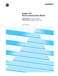
The VME DLAN/DLAN+ Interface Module, from GE Fanuc Automation North America, Inc.,
is a high-performance interface between the GE Drive Systems DLAN and DLAN+ local area
network (LAN) protocols and VMEbus based computer systems.
Revisions to This Manual
This version (GFK-1044A) of the VME DLAN/DLAN+ Interface Module User’s Manual has
changes to two chapters. In Chapter 1, Figure 1-1 has been revised to show the DLAN
configuration jumpers. Section 2 of Chapter 2 now describes DLAN jumper configuration.
Previously numbered Section 2 is now Section 3..
Content of this Manual
This manual contains the following chapters:
Chapter 1. Introduction: describes the features of the VME DLAN Interface module. The
basic operation of DLAN applications is also introduced in this chapter.
Chapter 2. Installation and Initialization: explains how to install and configure the VME
DLAN Interface module in a VME computer system.
Appendix A. Example C Program to Initialize a VME DLAN Interface Module: shows you
how to write application code to initialize the DLAN module.
Related DLAN Interface Module Publications
For more information, refer to these publications:
Important Product Information for VME DLAN/DLAN+ Interface Module (GFK-1049).
Data Sheet for DLAN/VME DLAN Interface Module (GFK-0728)
iii
GFK-1044A
Preface
We Welcome Your Comments and Suggestions
At GE Fanuc Automation, we strive to produce quality technical documentation. After you
have used this manual, please take a few moments to complete and return the Reader’s
Comment Card located on the next page.
Henry A. Konat
Senior Technical Writer
iv
VME DLAN/DLAN+ Interface Module User’s Manual - August 1995
GFK-1044A
Contents
Chapter 1
Introduction . . . . . . . . . . . . . . . . . . . . . . . . . . . . . . . . . . . . . . . . . . . . . . .
1-1
Section 1: System Overview . . . . . . . . . . . . . . . . . . . . . . . . . . . . . . . . .
1-1
DLAN Basics . . . . . . . . . . . . . . . . . . . . . . . . . . . . . . . . . . . . . . . . . . . . . . . . . .
1-1
VME DLAN Interface Module Functions . . . . . . . . . . . . . . . . . . . . . . . . . . . .
1-2
VME DLAN Applications . . . . . . . . . . . . . . . . . . . . . . . . . . . . . . . . . . . . . . . .
1-2
Section 2: DLAN Interface Module Description . . . . . . . . . . . . . . . .
Chapter 2
1-3
LED Indicators . . . . . . . . . . . . . . . . . . . . . . . . . . . . . . . . . . . . . . . . . . . . . . . . .
1-3
Address Select Jumpers . . . . . . . . . . . . . . . . . . . . . . . . . . . . . . . . . . . . . . . . . .
1-4
Restart Pushbutton . . . . . . . . . . . . . . . . . . . . . . . . . . . . . . . . . . . . . . . . . . . . . .
1-4
DLAN Network Connector . . . . . . . . . . . . . . . . . . . . . . . . . . . . . . . . . . . . . . .
1-5
DLAN Configuration Jumpers . . . . . . . . . . . . . . . . . . . . . . . . . . . . . . . . . . . . .
1-5
Battery . . . . . . . . . . . . . . . . . . . . . . . . . . . . . . . . . . . . . . . . . . . . . . . . . . . . . . .
1-5
Serial Connectors . . . . . . . . . . . . . . . . . . . . . . . . . . . . . . . . . . . . . . . . . . . . . . .
1-5
Installation and Initialization . . . . . . . . . . . . . . . . . . . . . . . . . . . . . . . . .
2-1
What You Will Need . . . . . . . . . . . . . . . . . . . . . . . . . . . . . . . . . . . . . . . . . . . .
2-1
Section 1: Installing the DLAN Interface module Hardware . . . . . .
2-2
Overview . . . . . . . . . . . . . . . . . . . . . . . . . . . . . . . . . . . . . . . . . . . . . . . . . . . . . .
2-2
Setting the Address Select Jumpers . . . . . . . . . . . . . . . . . . . . . . . . . . . . . . . . .
2-2
Installing a VME DLAN Interface Module . . . . . . . . . . . . . . . . . . . . . . . . . . .
2-3
Section 2: DLAN Jumper Configuration . . . . . . . . . . . . . . . . . . . . . . .
2-5
DLAN Configuration Jumpers . . . . . . . . . . . . . . . . . . . . . . . . . . . . . . . . . . . . .
2-5
Selecting the DLAN Network Type . . . . . . . . . . . . . . . . . . . . . . . . . . . . . . . . .
2-6
Selecting RS-485 Termination Resistors . . . . . . . . . . . . . . . . . . . . . . . . . . . . .
2-6
Section 3: Initializing the VMEbus Interface . . . . . . . . . . . . . . . . . .
2-8
Required Initialization Data . . . . . . . . . . . . . . . . . . . . . . . . . . . . . . . . . . . . . . .
2-8
The Initialization Process . . . . . . . . . . . . . . . . . . . . . . . . . . . . . . . . . . . . . . . . .
2-9
Addressing the Target VME DLAN Module . . . . . . . . . . . . . . . . . . . . . . . . . .
2-9
Writing Initialization Data . . . . . . . . . . . . . . . . . . . . . . . . . . . . . . . . . . . . . . . .
2-9
Reading the DLAN Module’s Acknowledgment . . . . . . . . . . . . . . . . . . . . . . .
2-9
Status Data Available from a DLAN Module . . . . . . . . . . . . . . . . . . . . . . . . .
2-10
Module ID String . . . . . . . . . . . . . . . . . . . . . . . . . . . . . . . . . . . . . . . . . . . . . . . . 2-10
Power-Up Diagnostics Result . . . . . . . . . . . . . . . . . . . . . . . . . . . . . . . . . . . . . . 2-10
Appendix A
GFK-1044A
Example C Program to Initialize a VME DLAN Interface Module . .
Table of Contents
A-1
v
Contents
vi
VME DLAN/DLAN+ Interface Module User’s Manual - August 1995
GFK-1044A
restart lowapp ARestart oddapp: ARestarts for autonumbers that do not restart in each
chapter. figure bi level 1, reset table_big level 1, reset chap_big level 1, reset1 Lowapp
Alwbox restart evenap:A1app_big level 1, resetA figure_ap level 1, reset table_ap level
1, reset figure level 1, reset table level 1, reset these restarts oddbox reset: 1evenbox
reset: 1must be in the header frame of chapter 1. a:ebx, l 1 resetA a:obx:l 1, resetA
a:bigbx level 1 resetA a:ftr level 1 resetA c:ebx, l 1 reset1 c:obx:l 1, reset1 c:bigbx level
1 reset1 c:ftr level 1 reset1 Reminders for autonumbers that need to be restarted
manually (first instance will always be 4) let_in level 1: A. B. C. letter level 1:A.B.C.
num level 1: 1. 2. 3. num_in level 1: 1. 2. 3. rom_in level 1: I. II. III. roman level 1: I. II.
III. steps level 1: 1. 2. 3.
Chapter
1 Introduction
1
This chapter provides a system overview of the VME DLAN/DLAN+ Interface module and a
description of the module’s hardware items. Section 1 describes the basics of the VME
DLAN/DLAN+ Interface module, its functions, and its application in a system.
Section 1: System Overview
The VME DLAN/DLAN+ Interface Module (catalog number IC697BEM764), from GE Fanuc
Automation North America, Inc., is a high-performance interface between the GE Drive
Systems DLAN and DLAN+ local area network (LAN) protocols and standard VMEbus control
systems. It permits DC300, AC2000, and DC2000 drives to be controlled from application
programs running in VME-based computers.
In this manual, the module will usually be referred to simply as the DLAN Interface module.
The reader should keep in mind that it supports both GE Drive Systems network protocols.
DLAN Basics
GE Drive systems devices communicate using one (or both, in some cases) of two types of
network protocol:
H
DLAN, a multidrop serial protocol - sometimes referred to as DLAN– or old DLAN.
H
DLAN+, a high speed protocol based on Arcnet.
Information is shared on the network using data pages. A page is a collection of 16 bit data
words. Each device (or drop) is allocated one or more pages. Each page may contain up to 256
words and is partitioned into blocks of 16 words each. DLAN supports 32 pages per network,
and DLAN+ supports 255 pages per network. The information within a page (its data structure)
depends on the device and is often referred to as a dialect. Devices with multiple pages may
use a different dialect for each page.
Each device is responsible for periodically detecting changes in its page(s) of information and
then broadcasting any changes on the network. This is the mechanism used by controllers, such
as the DLAN Interface module, to maintain an up-to-date copy of the data in other network
devices.
Controllers issue commands to other devices on the network by sending messages. Command
messages may be directed to a specific target device or broadcast, and may contain one new
data item for the device’s data page(s).
GFK-1044A
1-1
1
VME DLAN Interface Module Functions
The VME DLAN Interface module can operate as either a DLAN or DLAN+ controller.
However, a single module can not be both a DLAN and DLAN+ controller at the same time. If
the application requires both DLAN and DLAN+ devices, two DLAN Interface modules must
be used.
The module passes page data and commands between network devices and a CPU application
program. The knowledge about what the network devices are intended to do is contained in the
CPU program.
VME DLAN Applications
Hardware Requirements
The minimum hardware configuration for a VME DLAN or DLAN+ application requires these
components:
1.
A VME-based computer system that includes (at least) a rack, power supply, and CPU
module to run the application program.
2.
One or more VME DLAN Interface modules installed in another slot or slots.
3.
A DLAN or DLAN+ network connected to each DLAN Interface module.
4.
One or more GE Drive Systems devices connected to each network.
Typically, additional VME modules will also be required to monitor and control the application.
However, the discussion in this manual is limited to the DLAN Interface module and the
associated CPU program.
1-2
VME DLAN/DLAN+ Interface Module User’s Manual - August 1995
GFK-1044A
1
Section 2: DLAN Interface Module Description
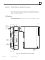
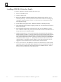
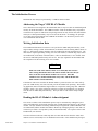
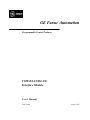
This section describes hardware items of interest to the user that are on the DLAN Interface
module. These items are: three LED status indicators, a restart pushbutton, a DLAN interface
connector, and address select jumpers.
LED Indicators
The three LED indicators, shown in the following figures, are mounted along the top front edge
of the DLAN Interface module.
a47040
DOOR
MODULE OK
COMMAND OUT
DATA IN
RESTART
Î
Î
BEM 764
MODULE OK
COMMAND OUT
DATA IN
ON = OK, ACTIVE
OTHER LEDS FOR
FACTORY USE.
PUSH TO RESTART
COMMUNICATION.
DLAN
CONNECTOR
DLAN
NETWORK
CONNECTOR
TXATXA+
TXBTXB+
5V
0V
TX
RX
1
2
3
4
5
6
7
8
(D CONNECTORS
NOT USED)
DLAN
CONFIGURATION
JUMPERS
Î
Î
MODULE FUNCTION
GE DRIVES
DLAN INTERFACE
MODULE:
IC697BEM764
LABEL:
44A726758-141R01
Î
Î
Î
Î
Î
Î
Î
Î
Î
H
L
JP1
JP2
JP3
JP4
ADDRESS
SELECT
JUMPERS
Figure 1-1. VME DLAN/DLAN+ Interface Module
GFK-1044A
Chapter 1 Introduction
1-3
1
MODULE OK LED
The MODULE OK LED indicates the current status of the DLAN Interface module. It has
three states:
Table 1-1. MODULE OK LED Status
State
Description
Off
When the MODULE OK LED is off, the DLAN Interface module is not functioning. This is
the result of a hardware malfunction; for example, the diagnostic checks
detected a failure. Corrective action is required in order to get the module
functioning again.
On
When the LED is on steadily, the DLAN Interface module is functioning properly. Normally,
this LED should always be on, indicating that both the diagnostic tests
and the initialization by the VME CPU were successfully completed.
Flashing
The LED flashes rapidly during power-up diagnostics and then more slowly while it waits for
initialization by the CPU.
Note
The DLAN Interface module has a hardware watchdog timer that is periodically
reset by the module software. If the watchdog timer expires, the module stops
functioning and the MODULE OK LED turns off.
COMMAND OUT LED
The center LED indicator, referred to as COMMAND OUT on the module door label, has two
functions. It flashes on briefly during the self test that occurs when the VME rack is powered
on or the module Restart pushbutton is pressed. During normal operation, it flashes whenever a
command from the CPU application program is sent to a network drop.
DATA IN LED
The lower LED indicator, referred to as DATA IN on the module door label, flashes whenever a
page data update message is received from one of the network drops. Most frequently, these
messages contain feedback data. If none of the drops broadcasts an update message, this LED
will flash every two seconds as long as any active drops are connected to the network.
Address Select Jumpers
The address select jumpers, JP1 through JP4, are used to select the VME base address that the
VME DLAN module will respond to in VME short non-privileged mode. See chapter 2, section
1 of this manual for details.
Restart Pushbutton
Pressing the Restart pushbutton for any length of time will halt DLAN communication and
cause the module to perform its internal tests. The CPU application program must detect this
condition and send new DLAN configuration data in order for communication to restart
automatically.
1-4
VME DLAN/DLAN+ Interface Module User’s Manual - August 1995
GFK-1044A
1
DLAN Network Connector
This eight-pin connector provides a means of connecting the DLAN Interface module to the
DLAN or DLAN+ network. A connector on the cable from the DLAN network connection
block mates to the connector on the module.
DLAN Configuration Jumpers
These jumpers are used to configure the network connection when the Network Type is
specified as DLAN. JP2 through JP4 are used to select either the optically isolated LAN
network or an RS-485 LAN network. If the RS-485 LAN network is selected, JP5 and JP6 are
used to select whether the RS-485 network termination resistors are IN or OUT.
Battery
The DLAN Interface module does not use a battery.
Serial Connectors
The two DB-25S serial connectors on the DLAN Interface module are not used.
GFK-1044A
Chapter 1 Introduction
1-5
Chapter
1 Installation and Initialization
2
section level 1 1
figure bi level 1
table_big level 1
This chapter explains how to install a DLAN Interface module in a VME system and the
software initialization that must occur before the module can operate. There are several easy
steps in preparing the DLAN Interface module for use.
The chapter is divided into three sections. The necessary equipment and software packages
required for the installation process are described below. After that, each section describes one
step of the installation procedure in detail.
Step 1. Installing the DLAN Interface Module Hardware: Refer to Section 1 for a
description of the physical installation of the DLAN Interface module in a VME rack. A
description of the module hardware is also included.
Step 2. DLAN Jumper Configuration: Section 2 describes how to set the DLAN
configuration jumpers located on the DLAN daughter board when a DLAN network (rather than
DLAN+ network) is used.
Step 3. Software Initialization of the DLAN Interface Module Bus Interface: Section 3
describes the steps that must be performed by the VME CPU to initialize the VMEbus interface
hardware in the DLAN Interface module.
What You Will Need
Before you can begin the installation procedure, you must have the following equipment and
software:
GFK-1044A
H
A VMEbus based computer system that includes (at least) a VME rack, power supply, and
CPU module.
H
One or more VME DLAN Interface modules.
H
An application development platform and tools for the VME CPU.
2-1
2
Section 1: Installing the DLAN Interface module Hardware
The first step in the installation procedure is to set the base address jumpers for VME short
non-privileged access mode. Then, the DLAN Interface module must be installed in a VME
rack.
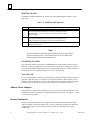
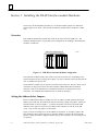
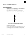
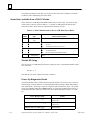
Overview
Each VME DLAN Interface module must reside in the same rack as the VME CPU. The
following illustration shows one possible system configuration for installing a DLAN Interface
module in a VME rack.
ÎÎ
ÎÎÎ
ÎÎ
ÎÎÎÎ
ÎÎÎÎÎ
Î
ÎÎ
Î
ÎÎ
ÎÎ
ÎÎ
Î
ÎÎ
ÎÎ
ÎÎ
Î
ÎÎ
Î
ÎÎ
ÎÎ
ÎÎ
Î
ÎÎ
ÎÎ
ÎÎ
Î
ÎÎ
Î
ÎÎ
ÎÎ
Î
Î
ÎÎ
ÎÎÎ
ÎÎ
ÎÎ
ÎÎÎÎ
ÎÎÎ
ÎÎ
ÎÎÎÎ
ÎÎ
Î
ÎÎ
ÎÎÎ
ÎÎ
ÎÎÎÎ
ÎÎÎÎÎ
Î
VME RACK CONFIGURATION
P
S
a47041
C D
P L
U A
N
Figure 2-1. VME DLAN Interface Module Configuration
The VME CPU modules usually must reside in a specific slot in the rack. Depending on the
specific hardware, the power supply (PS in figure 2-1) may be external to the rack, built into the
rack, or installed in a specific slot.
DLAN Interface modules may be placed in any unused slot in the rack. However, there may be
restrictions on empty slots between the CPU and other VME modules that use hardware
interrupts. Refer to the manufacturer’s installation instructions for information on such
restrictions. The VME DLAN module does not use hardware interrupts.
Setting the Address Select Jumpers
Before a VME DLAN module is installed in a rack, its address in VME short non-privileged
address space (AM code 29 hexadecimal) must be selected by setting four jumpers. When you
hold the module as shown in Figure 1-1, with the component side toward you and the LED
indicators in the upper left corner, the four address select jumpers are near the lower right
corner. They are the only jumpers on the module.
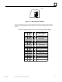
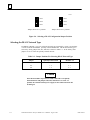
Figure 2-2 shows an enlarged view of the address select jumpers. In the figure, jumpers JP1,
JP2, and JP4 are shown in the logic low (L) position; and JP3 is shown in the logic high (H)
position. When the module is shipped from the factory, all four jumpers are set to the logic low
(L) position.
2-2
VME DLAN/DLAN+ Interface Module User’s Manual - August 1995
GFK-1044A
2
a47042
H
L
JP1
JP2
JP3
JP4
Figure 2-2. Address Selection Jumpers
There are 16 possible ways to set the four jumpers, and each one provides a unique range of
short non-privileged addresses for the module. Table 2-1 shows the address range for each
setting.
Table 2-1. Jumper Settings for Short Non-Privileged Address Range
ÁÁÁ
ÁÁÁ
ÁÁÁ
ÁÁ
ÁÁÁÁÁÁÁÁÁ
ÁÁÁ
ÁÁÁ
ÁÁÁ
ÁÁ
ÁÁÁÁÁÁÁÁÁ
ÁÁÁ
ÁÁÁ
ÁÁ
ÁÁÁÁÁÁÁÁÁ
ÁÁÁ
ÁÁÁ
ÁÁÁ
ÁÁÁ
ÁÁ
ÁÁÁÁÁÁÁÁÁ
ÁÁÁ
ÁÁÁ
ÁÁÁ
ÁÁ
ÁÁÁÁÁÁÁÁÁ
ÁÁÁ
ÁÁÁ
ÁÁÁ
ÁÁ
ÁÁÁÁÁÁÁÁÁ
ÁÁÁ
ÁÁÁ
ÁÁÁ
ÁÁ
ÁÁÁÁÁÁÁÁÁ
ÁÁÁ
ÁÁÁ
ÁÁÁ
ÁÁ
ÁÁÁÁÁÁÁÁÁ
ÁÁÁ
ÁÁÁ
ÁÁÁ
ÁÁ
ÁÁÁÁÁÁÁÁÁ
ÁÁÁ
ÁÁÁ
ÁÁÁ
ÁÁ
ÁÁÁÁÁÁÁÁÁ
ÁÁÁ
ÁÁÁ
ÁÁÁ
ÁÁ
ÁÁÁÁÁÁÁÁÁ
ÁÁÁ
ÁÁÁ
ÁÁÁ
ÁÁ
ÁÁÁÁÁÁÁÁÁ
ÁÁÁ
ÁÁÁ
ÁÁÁ
ÁÁ
ÁÁÁÁÁÁÁÁÁ
ÁÁÁ
ÁÁÁ
ÁÁÁ
ÁÁ
ÁÁÁÁÁÁÁÁÁ
ÁÁÁ
ÁÁÁ
ÁÁÁ
ÁÁ
ÁÁÁÁÁÁÁÁÁ
ÁÁÁ
ÁÁÁ
ÁÁÁ
ÁÁ
ÁÁÁÁÁÁÁÁÁ
ÁÁÁ
ÁÁÁ
ÁÁÁ
ÁÁ
ÁÁÁÁÁÁÁÁÁ
ÁÁÁ
ÁÁÁ
ÁÁÁ
ÁÁ
ÁÁÁÁÁÁÁÁÁ
ÁÁÁ
ÁÁÁ
ÁÁÁ
ÁÁ
ÁÁÁÁÁÁÁÁÁ
GFK-1044A
JP4
JP3
JP2
JP1
Short Non-Privileged
Address Range
(Hexadecimal)
L
L
L
L
L
L
L
L
H
H
H
H
H
H
H
H
L
L
L
L
H
H
H
H
L
L
L
L
H
H
H
H
L
L
H
H
L
L
H
H
L
L
H
H
L
L
H
H
L
H
L
H
L
H
L
H
L
H
L
H
L
H
L
H
0000 - 07FF
0800 - 0FFF
1000 - 17FF
1800 - 1FFF
2000 - 27FF
2800 - 2FFF
3000 - 37FF
3800 - 3FFF
4000 - 47FF
4800 - 4FFF
5000 - 57FF
5800 - 5FFF
6000 - 67FF
6800 - 6FFF
7000 - 77FF
7800 - 7FFF
Chapter 2 Installation and Initialization
2-3
2
Installing a VME DLAN Interface Module
To install a VME DLAN Interface module, follow these steps:
2-4
1.
Power off the VME system.
2.
Locate the desired slot.
3.
Remove the VME DLAN Interface module from the shipping carton, but leave it in its
anti-static plastic bag. Touch an exposed metal surface of the VME rack to discharge any
electrostatic charge you may have picked up. Then remove the DLAN Interface module
from the protective bag.
4.
Set the address select jumpers on the VME DLAN module as described previously.
5.
Slide the DLAN Interface module completely into the slot. The three LEDs are located at
the top of the module.
6.
Press the module firmly against the front rails of the PLC rack, but do not use excessive
force. When the module is fully seated, you will hear and/or feel clicks from the latches on
the top and bottom of the module faceplate.
7.
Mount the DLAN/DLAN+ network connection block to the VME rack where the DLAN
Interface module is installed. Connect the ground wire from the connection block securely
to one of the ground screws on the VME rack. Connect the cable from the connection
block to the DLAN Interface module by mating its connector with the DLAN NETWORK
CONNECTOR shown in Figure 1-1. Finally, connect the network cable or cables to the
connection block. If the DLAN Interface module is at one end of the network cable, the
appropriate network terminator must be connected at the connection block.
8.
Power on the VME rack. The MODULE OK LED of the DLAN Interface module should
immediately begin to flash rapidly. When diagnostics tests have completed, the LED will
flash at a slower rate until setup data has been written to its VMEbus interface. Refer to
the next section for information on the required setup.
VME DLAN/DLAN+ Interface Module User’s Manual - August 1995
GFK-1044A
2
Section 2: DLAN Jumper Configuration
DLAN Configuration Jumpers
When a DLAN network (rather than DLAN+ network) is used, jumpers on the DLAN daughter
board must be used to configure the network connection. This section describes how to set the
jumpers. If you are using a DLAN+ network, skip this section.
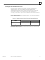
Figure 2-3 is an enlarged view of the DLAN configuration jumpers shown in Figure 1-1.
Jumper JP6 is nearest the DLAN network connector. The positions of these jumpers configure
the DLAN module connections to a DLAN network.
a47078
JP6
JP5
JP4
JP3
JP2
Figure 2-3. Detail of DLAN Configuration Jumpers From Figure 1-1.
Figure 2-4 shows the two possible positions for jumpers JP2 through JP6. All of the jumpers
are installed in the 1-2 position at the factory.
If you need to change one or more jumper positions, use this procedure. Each jumper has a thin
tab that extends beyond the edge of the DLAN daughter board toward the front of the module.
Grip the tab with needle nose pliers and pull it forward until it is free. Then move the jumper
so that it will engage pins 2 and 3, and push it onto the pins. Repeat for each jumper that needs
to be changed.
GFK-1044A
Chapter 2 Installation and Initialization
2-5
2
a47079
Pin 3
Pin 3
Pin 2
Pin 2
Pin 1
Pin 1
Jumper shown in 1-2 position.
Jumper shown in 2-3 position.
Figure 2-4. Selecting a DLAN Configuration Jumper Position
Selecting the DLAN Network Type
In addition to DLAN+, two types of DLAN networks are supported by version 1.04 and later
versions of the DLAN Module: optically isolated and RS-485. The DLAN network type is
selected by setting jumpers JP2, JP3, and JP4, as shown in Table 2-1. At the factory, these
jumpers are set to select the optically isolated network.
Table 2-2. Jumper Positions For Selecting DLAN Network Type
Jumper
Optically Isolated LAN
RS-485 LAN
JP2
1–2
2–3
JP3
1–2
2–3
JP4
1–2
2–3
Caution
If the DLAN modules is powered on while connected to an optically
isolated network and jumpers JP2, JP3, and JP4 are set to the 2–3
position, the external isolated power supply for the isolated network will
be damaged.
2-6
VME DLAN/DLAN+ Interface Module User’s Manual - August 1995
GFK-1044A
2
Selecting RS-485 Termination Resistors
If the RS-485 network is selected, the drop at each end of the network cable should have the
termination resistors IN. This is true for all drop types, both DLAN modules and drives.
Adding additional termination resistors will improve the signal to noise ratio of RS-485
networks, but more than five sets of termination resistors will overload the drivers.
Accordingly, no more than five drops on a network should have the termination resistors IN.
Table 2–2 shows the jumper settings for termination resistors. At the factory, these jumpers are
set for termination resistors IN.
Table 2-3. Jumper Positions For RS-485 Network Termination Resistors
Termination Resistors
Jumper
IN
OUT
JP5
1–2
2–3
JP6
1–2
2–3
If the optically isolated network is selected, the termination resistors are not used, and the JP5
and JP6 jumper settings are ignored.
GFK-1044A
Chapter 2 Installation and Initialization
2-7
2
Section 3: Initializing the VMEbus Interface
Each VME DLAN module must be initialized by writing to its VMEbus memory from the VME
CPU or other VME module before the DLAN module can be used. This initialization must
occur each time a rack containing a DLAN module is powered on.
The DLAN module is not permitted to execute until after initialization has occurred. The module will wait indefinitely for its initialization data. During this time, the Module OK LED (the
topmost LED) continues to flash on and off. After initialization, the LED remains on continuously.
The initialization may be performed by any VME module that has short non-privileged write
access to VME dual-ported memory in the DLAN module. However, initialization is usually
performed by the VME CPU.
For example initialization code, see appendix A, Example C Program to Initialize a VME
DLAN Module.
Required Initialization Data
VME DLAN initialization data consists of 64 contiguous bytes. Most of these bytes contain zero.
Byte locations where non-zero data is required are shown in table 2-2. All bytes in the range 0
through 63, inclusive, that are not specified in table 2-2 must be set to zero.
ÁÁÁÁÁÁ
ÁÁÁÁÁÁÁÁÁÁÁÁÁÁÁ
ÁÁÁÁÁÁÁÁ
ÁÁÁÁÁÁ
ÁÁÁÁÁÁÁÁÁÁÁÁÁÁÁ
ÁÁÁÁÁÁÁÁ
ÁÁÁÁÁÁ
ÁÁÁÁÁÁÁÁÁÁÁÁÁÁÁ
ÁÁÁÁÁÁÁÁ
ÁÁÁÁÁÁÁÁÁÁÁÁÁÁÁ
ÁÁÁÁÁÁ
ÁÁÁÁÁÁÁÁ
ÁÁÁÁÁÁ
ÁÁÁÁÁÁÁÁÁÁÁÁÁÁÁ
ÁÁÁÁÁÁÁÁ
ÁÁÁÁÁÁÁÁÁÁÁÁÁÁÁ
ÁÁÁÁÁÁ
ÁÁÁÁÁÁÁÁ
ÁÁÁÁÁÁ
ÁÁÁÁÁÁÁÁÁÁÁÁÁÁÁ
ÁÁÁÁÁÁÁÁ
ÁÁÁÁÁÁ
ÁÁÁÁÁÁÁÁÁÁÁÁÁÁÁ
ÁÁÁÁÁÁÁÁ
ÁÁÁÁÁÁ
ÁÁÁÁÁÁÁÁ
ÁÁÁÁÁÁÁÁÁÁÁÁÁÁÁ
ÁÁÁÁÁÁ
ÁÁÁÁÁÁÁÁÁÁÁÁÁÁÁ
ÁÁÁÁÁÁÁÁ
Table 2-4. Required Setup Data
Zero-Based
Byte Offset
(Hexadecimal)
Description
Required Value
or Range
(Hexadecimal)
5
Bits 16 through 23 of the target module’s start
address in VME 24-bit standard non-privileged address
space.
0 ... FF
9
Standard non-privileged address modifier code.
39
28
Flag indicating the CPU has identified the target module
as a VME DLAN module.
80
3F
Flag indicating valid setup data is available.
FE
VME dual-ported memory in the VME DLAN module is 64K bytes wide. Its starting address
in VME standard non-privileged address space must be set at a 64K byte boundary. Consequently, bits 0 through 15, inclusive, of the start address specified in the module’s initialization
data must be zero.
The DLAN module VME memory may be located on any 64K byte boundary in the 16
megabyte VME A24 address space. Accordingly, the value assigned to start address bits 16 23, in byte offset five of the setup data, may be any value in the range 0 through 0FF
hexadecimal (0 through 255 decimal).
2-8
VME DLAN/DLAN+ Interface Module User’s Manual - August 1995
GFK-1044A
2
The Initialization Process
Initialization must always be performed by a VME bus master module.
Addressing the Target VME DLAN Module
Once values have been assigned to the initialization data, it may be written to VME dual-ported
memory in the DLAN module. The VMEbus interface of DLAN modules always responds to
read and write requests in VME short non-privileged mode, but only the first 2K (800 hexadecimal) bytes of dual-ported memory may be accessed in this mode. Accordingly, the principal
use of short non-privileged mode with VME DLAN modules is to detect their presence and
write initialization data to them.
Writing Initialization Data
The initialization data must be written to a 64 byte block of VME dual-ported memory in the
target module, starting at offset 40 hexadecimal (64 decimal) from the starting address shown in
table 2-1, and using the address modifier code 29 hexadecimal and 8 bit (D8) data access. The
data must be copied sequentially, starting at its low order address, so that the flag at byte offset
3F hexadecimal (63 decimal) of the data (that is, offset 7F hexadecimal, or 127 decimal, from
the start of VME dual-ported memory) arrives last. This byte signals the DLAN module that
the setup data it has been waiting for is now available.
Caution
With some VME CPU modules, failure to use 8 bit (D8) data transfers
when writing initialization data to the DLAN module will cause the byte
order of the data in the DLAN module to be reversed. When this
condition occurs, module initialization always fails, and the Module OK
LED continues to flash indefinitely.
If the data is written too soon after the DLAN module is powered on, the new values will appear to be VME memory test errors and will prevent the module from operating. The initializing application must wait until the target module is ready before writing setup data. When the
module is ready, a zero value will appear in the byte at offset 7F hexadecimal (127 decimal)
from the start of VME dual-ported memory. The byte must be read in short non-privileged
mode.
Reading the DLAN Module’s Acknowledgment
The success or failure of the initialization process may be determined by reading the byte at
offset 7F hexadecimal (127 decimal) from the start of VME dual-ported memory in the DLAN
module. The byte should be read using standard non-privileged mode (Address Modifier code
39 hexadecimal) and the module start address obtained by multiplying the byte value that was
written to byte offset 5 of setup data by 64K (10000 hexadecimal). The expected value is 0FF
hexadecimal (255 decimal).
The interval between the time when setup data is written and the time when the status value
indicates success will usually be a few hundred microseconds. If the standard non-privileged
GFK-1044A
Chapter 2 Installation and Initialization
2-9
2
read operation continues to fail after one second, or some other value is obtained, you should
assume the entire initialization process has failed.
Status Data Available from a DLAN Module
Three locations in VME dual-ported RAM contain one byte status codes. The locations and
values of these codes are shown in Table 2-3. Locations for additional status data are also
shown in the table. These items are explained in the following sections.
ÁÁÁÁ
ÁÁÁÁÁÁÁ
ÁÁÁÁÁÁÁÁÁÁÁÁÁÁÁÁÁ
ÁÁÁÁ
ÁÁÁÁÁÁÁ
ÁÁÁÁÁÁÁÁÁÁÁÁÁÁÁÁÁ
ÁÁÁÁÁÁÁ
ÁÁÁÁ
ÁÁÁÁÁÁÁÁÁÁÁÁÁÁÁÁÁ
ÁÁÁÁ
ÁÁÁÁÁÁÁ
ÁÁÁÁÁÁÁÁÁÁÁÁÁÁÁÁÁ
ÁÁÁÁ
ÁÁÁÁÁÁÁ
ÁÁ
ÁÁÁÁÁÁÁÁÁÁÁÁÁÁÁÁ
ÁÁÁÁÁÁÁÁÁÁÁÁÁÁÁÁÁ
ÁÁÁÁ
ÁÁÁÁÁÁÁ
ÁÁ
ÁÁÁÁÁÁÁÁÁÁÁÁÁÁÁÁ
ÁÁÁÁ
ÁÁÁÁÁÁÁ
ÁÁ
ÁÁÁÁÁÁÁÁÁÁÁÁÁÁÁÁÁ
ÁÁÁÁÁÁÁÁÁÁÁÁÁÁÁÁ
ÁÁÁÁÁÁÁÁÁÁÁÁÁÁÁÁÁ
ÁÁÁÁ
ÁÁÁÁÁÁÁ
ÁÁ
ÁÁÁÁÁÁÁÁÁÁÁÁÁÁÁÁ
ÁÁÁÁ
ÁÁÁÁÁÁÁ
ÁÁ
ÁÁÁÁÁÁÁÁÁÁÁÁÁÁÁÁ
ÁÁÁÁ
ÁÁÁÁÁÁÁ
ÁÁÁÁÁÁÁÁÁÁÁÁÁÁÁÁÁ
ÁÁ
ÁÁÁÁÁÁÁÁÁÁÁÁÁÁÁÁ
ÁÁÁÁ
ÁÁÁÁÁÁÁ
ÁÁÁÁÁÁÁÁÁÁÁÁÁÁÁÁÁ
Table 2-5. DLAN Module Status Codes in VME Dual-Ported RAM
Byte
Offset
13
39
3B
0B2
Type
11-byte character
array
Byte
Byte
NUL-terminated
ASCII string
Values and Description
Module ID string (See Module ID String, below).
Module error code (Hexadecimal):
0:
No error.
0C:
The daughter board type is incorrect.
Daughter board ID code (Hexadecimal):
40:
No daughter board .
5B:
DLAN communication daughter board.
Power-up diagnostics result (See Power-Up Diagnostics Result,
below).
Module ID String
The eleven bytes of VME dual-ported memory starting at offset 13 hexadecimal should contain
these characters.
B E M 7 6 4
Note that the even bytes contain ASCII space characters.
Power-Up Diagnostics Result
The DLAN Module self-test routines that run when the module is powered on copy a NUL-terminated string of ASCII characters to VME dual-ported RAM, starting at offset 0B2 hexadecimal (178 decimal). The string is copied to contiguous (both odd and even) bytes. The normal
string value is Diag Req 111 Completed(1); any other string indicates that an error occurred during the tests. The nature of the error can be determined from the string. For example:
Error Message String
2-10
Failure
ROM CRC is xxxx not yyyy!
Checksum failure of EPROM at board
location U60.
ACC chksum is xxxx not yyyy
Checksum failure of EPROM at board
location U59.
RAM failure at xxxx:yyyy!
RAM test failure.
VME DLAN/DLAN+ Interface Module User’s Manual - August 1995
GFK-1044A
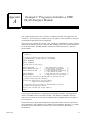
Appendix A Example C Program to Initialize a VME
DLAN Interface Module
A
This example program shows how to initialize a VME DLAN module from application code
written in C. See Initializing the VMEbus Interface in chapter 2 of this manual for a discussion
of initialization requirements and for suggestions.
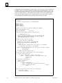
Three source files constitute the example. First, a header file, DLANINIT.H, specifies constant
definitions and function prototypes. Function vme_setup performs the required initialization
for the DLAN module, and vme_status monitors the initialization status of a specified
DLAN module.
ÁÁÁÁÁÁÁÁÁÁÁÁÁÁÁÁÁÁÁÁÁÁÁÁÁ
ÁÁÁÁÁÁÁÁÁÁÁÁÁÁÁÁÁÁÁÁÁÁÁÁÁ
ÁÁÁÁÁÁÁÁÁÁÁÁÁÁÁÁÁÁÁÁÁÁÁÁÁ
ÁÁÁÁÁÁÁÁÁÁÁÁÁÁÁÁÁÁÁÁÁÁÁÁÁ
ÁÁÁÁÁÁÁÁÁÁÁÁÁÁÁÁÁÁÁÁÁÁÁÁÁ
ÁÁÁÁÁÁÁÁÁÁÁÁÁÁÁÁÁÁÁÁÁÁÁÁÁ
ÁÁÁÁÁÁÁÁÁÁÁÁÁÁÁÁÁÁÁÁÁÁÁÁÁ
ÁÁÁÁÁÁÁÁÁÁÁÁÁÁÁÁÁÁÁÁÁÁÁÁÁ
ÁÁÁÁÁÁÁÁÁÁÁÁÁÁÁÁÁÁÁÁÁÁÁÁÁ
ÁÁÁÁÁÁÁÁÁÁÁÁÁÁÁÁÁÁÁÁÁÁÁÁÁ
ÁÁÁÁÁÁÁÁÁÁÁÁÁÁÁÁÁÁÁÁÁÁÁÁÁ
ÁÁÁÁÁÁÁÁÁÁÁÁÁÁÁÁÁÁÁÁÁÁÁÁÁ
ÁÁÁÁÁÁÁÁÁÁÁÁÁÁÁÁÁÁÁÁÁÁÁÁÁ
ÁÁÁÁÁÁÁÁÁÁÁÁÁÁÁÁÁÁÁÁÁÁÁÁÁ
ÁÁÁÁÁÁÁÁÁÁÁÁÁÁÁÁÁÁÁÁÁÁÁÁÁ
ÁÁÁÁÁÁÁÁÁÁÁÁÁÁÁÁÁÁÁÁÁÁÁÁÁ
ÁÁÁÁÁÁÁÁÁÁÁÁÁÁÁÁÁÁÁÁÁÁÁÁÁ
ÁÁÁÁÁÁÁÁÁÁÁÁÁÁÁÁÁÁÁÁÁÁÁÁÁ
/*
* dlaninit.h
*
* Constants and function prototypes for initializing
* a VME DLAN module, GE Fanuc catalog no. IC697BEM764.
*/
#ifndef _DLANINIT_H_
#define _DLANINIT_H_
/*
* Return values for vme_setup():
*/
#define SETUP_CMPLT
0
/* The initialization succeeded.
#define INVALID_SHORT_ADDR –1
/* specified short non–privileged
/*
start address is invalid
#define INVALID_STD_ADDR
–2
/* specified standard non–privileged
/*
start address is invalid
#define VME_ERROR
–3
/* Setup data write was not verified.
#define INIT_ERROR
–4
/* Target module did not acknowledge.
/*
* This function initializes a VME DLAN module at specified short and
* standard non–privileged base addresses.
*/
int vme_setup( unsigned short short_base_address,
unsigned long std_base_address );
/*
* This function checks the status of a VME DLAN module at specified
* standard non–privileged base address.
*/
int vme_status( unsigned long std_base_address );
#endif
*/
*/
*/
*/
*/
*/
*/
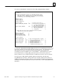
A test program, DLANTEST.C, is designed to be as portable as possible. This program was
tested in a standard Series 90-70 PCM711 module. The module was installed in the main
(CPU) rack of a Series 90-70 PLC that was substituted for the standard VME rack of figure 1-1
for test purposes.
Default short non-privileged and standard non-privileged base address values are specified as
macro definitions, but the defaults may be changed from command line parameters. To change
the defaults, specify both addresses as shown in one of the comments in the listing of
DLANTEST.C.
GFK-1044A
A-1
A
The main function in DLANTEST.C is quite simple. First, it tests the count of command line
arguments. If there are enough arguments to hold the short and standard address values, the
second and third argument strings are converted to unsigned integers, and the resulting values
replace the default addresses. Then, main prints the address values to the standard output
device and calls vme_setup to do the actual initialization of the target module. Finally, a
non-terminating loop initializes the target module and then monitors its status.
ÁÁÁÁÁÁÁÁÁÁÁÁÁÁÁÁÁÁÁÁÁÁÁÁÁ
ÁÁÁÁÁÁÁÁÁÁÁÁÁÁÁÁÁÁÁÁÁÁÁÁÁ
ÁÁÁÁÁÁÁÁÁÁÁÁÁÁÁÁÁÁÁÁÁÁÁÁÁ
ÁÁÁÁÁÁÁÁÁÁÁÁÁÁÁÁÁÁÁÁÁÁÁÁÁ
ÁÁÁÁÁÁÁÁÁÁÁÁÁÁÁÁÁÁÁÁÁÁÁÁÁ
ÁÁÁÁÁÁÁÁÁÁÁÁÁÁÁÁÁÁÁÁÁÁÁÁÁ
ÁÁÁÁÁÁÁÁÁÁÁÁÁÁÁÁÁÁÁÁÁÁÁÁÁ
ÁÁÁÁÁÁÁÁÁÁÁÁÁÁÁÁÁÁÁÁÁÁÁÁÁ
ÁÁÁÁÁÁÁÁÁÁÁÁÁÁÁÁÁÁÁÁÁÁÁÁÁ
ÁÁÁÁÁÁÁÁÁÁÁÁÁÁÁÁÁÁÁÁÁÁÁÁÁ
ÁÁÁÁÁÁÁÁÁÁÁÁÁÁÁÁÁÁÁÁÁÁÁÁÁ
ÁÁÁÁÁÁÁÁÁÁÁÁÁÁÁÁÁÁÁÁÁÁÁÁÁ
ÁÁÁÁÁÁÁÁÁÁÁÁÁÁÁÁÁÁÁÁÁÁÁÁÁ
ÁÁÁÁÁÁÁÁÁÁÁÁÁÁÁÁÁÁÁÁÁÁÁÁÁ
ÁÁÁÁÁÁÁÁÁÁÁÁÁÁÁÁÁÁÁÁÁÁÁÁÁ
ÁÁÁÁÁÁÁÁÁÁÁÁÁÁÁÁÁÁÁÁÁÁÁÁÁ
ÁÁÁÁÁÁÁÁÁÁÁÁÁÁÁÁÁÁÁÁÁÁÁÁÁ
ÁÁÁÁÁÁÁÁÁÁÁÁÁÁÁÁÁÁÁÁÁÁÁÁÁ
ÁÁÁÁÁÁÁÁÁÁÁÁÁÁÁÁÁÁÁÁÁÁÁÁÁ
ÁÁÁÁÁÁÁÁÁÁÁÁÁÁÁÁÁÁÁÁÁÁÁÁÁ
ÁÁÁÁÁÁÁÁÁÁÁÁÁÁÁÁÁÁÁÁÁÁÁÁÁ
ÁÁÁÁÁÁÁÁÁÁÁÁÁÁÁÁÁÁÁÁÁÁÁÁÁ
ÁÁÁÁÁÁÁÁÁÁÁÁÁÁÁÁÁÁÁÁÁÁÁÁÁ
ÁÁÁÁÁÁÁÁÁÁÁÁÁÁÁÁÁÁÁÁÁÁÁÁÁ
ÁÁÁÁÁÁÁÁÁÁÁÁÁÁÁÁÁÁÁÁÁÁÁÁÁ
ÁÁÁÁÁÁÁÁÁÁÁÁÁÁÁÁÁÁÁÁÁÁÁÁÁ
ÁÁÁÁÁÁÁÁÁÁÁÁÁÁÁÁÁÁÁÁÁÁÁÁÁ
ÁÁÁÁÁÁÁÁÁÁÁÁÁÁÁÁÁÁÁÁÁÁÁÁÁ
ÁÁÁÁÁÁÁÁÁÁÁÁÁÁÁÁÁÁÁÁÁÁÁÁÁ
ÁÁÁÁÁÁÁÁÁÁÁÁÁÁÁÁÁÁÁÁÁÁÁÁÁ
ÁÁÁÁÁÁÁÁÁÁÁÁÁÁÁÁÁÁÁÁÁÁÁÁÁ
ÁÁÁÁÁÁÁÁÁÁÁÁÁÁÁÁÁÁÁÁÁÁÁÁÁ
ÁÁÁÁÁÁÁÁÁÁÁÁÁÁÁÁÁÁÁÁÁÁÁÁÁ
ÁÁÁÁÁÁÁÁÁÁÁÁÁÁÁÁÁÁÁÁÁÁÁÁÁ
ÁÁÁÁÁÁÁÁÁÁÁÁÁÁÁÁÁÁÁÁÁÁÁÁÁ
ÁÁÁÁÁÁÁÁÁÁÁÁÁÁÁÁÁÁÁÁÁÁÁÁÁ
/*
* dlantest.c
*
* Program for testing vme_setup() in a VME DLAN module.
*/
#include <vtos.h>
#include <stdio.h>
#include <stdlib.h>
#include ”dlaninit.h”
/*
* Default values that may be replaced by command line arguments.
*/
#define SHORT_START_ADDR 0x1800
#define STD_START_ADDR
0x00020000L
/*
* Run from the PCM command interpreter prompt like this:
*
*
> R DLANTEST.EXE 1800 20000
*
*
where the two numeric arguments are the short non–privileged and
*
standart non–privileged start addresses, respectively, where a
*
target VME DLAN module will be accessed.
*/
void main( int argc, char far* far argv[] )
{
int status, last_status = SETUP_CMPLT;
unsigned short short_start_addr = SHORT_START_ADDR;
unsigned long std_start_addr = STD_START_ADDR;
if (argc > 2) {
short_start_addr = (unsigned short )(atol( argv[1] ) & 0x0000ffffL);
std_start_addr = atol( argv[2] ) & 0x00ffffffL;
}
printf( ”short non–priv start addr = %04x, std non–priv start addr = %08lx\n”,
short_start_addr,
std_start_addr );
for (;;) {
status = vme_status( std_start_addr );
/*
* If the target module is uninitialized or its status has changed:
*
Print the current status value.
*/
if (status != SETUP_CMPLT || status != last_status) {
printf(
”status of vme module at base address %08lx = %d\n”,
std_start_addr,
status );
/*
* If the module is uninitialized:
*
Attempt to initialize it.
*
Print the result.
*/
if (status != SETUP_CMPLT) {
status = vme_setup( short_start_addr, std_start_addr );
printf( ”new vme_setup() result
= %d\n\n”,
status );
}
}
/*
* Save the current status value and wait 1,000 milliseconds.
*/
last_status = status;
Wait_time( MS_COUNT_MODE, 0, 1000 );
}
}
A-2
VME DLAN/DLAN+ Interface Module User’s Manual - August 1995
GFK-1044A
A
The source file DLANINIT.C contains the code for vme_setup and vme_status.
ÁÁÁÁÁÁÁÁÁÁÁÁÁÁÁÁÁÁÁÁÁÁÁÁÁ
ÁÁÁÁÁÁÁÁÁÁÁÁÁÁÁÁÁÁÁÁÁÁÁÁÁ
ÁÁÁÁÁÁÁÁÁÁÁÁÁÁÁÁÁÁÁÁÁÁÁÁÁ
ÁÁÁÁÁÁÁÁÁÁÁÁÁÁÁÁÁÁÁÁÁÁÁÁÁ
ÁÁÁÁÁÁÁÁÁÁÁÁÁÁÁÁÁÁÁÁÁÁÁÁÁ
ÁÁÁÁÁÁÁÁÁÁÁÁÁÁÁÁÁÁÁÁÁÁÁÁÁ
ÁÁÁÁÁÁÁÁÁÁÁÁÁÁÁÁÁÁÁÁÁÁÁÁÁ
ÁÁÁÁÁÁÁÁÁÁÁÁÁÁÁÁÁÁÁÁÁÁÁÁÁ
ÁÁÁÁÁÁÁÁÁÁÁÁÁÁÁÁÁÁÁÁÁÁÁÁÁ
ÁÁÁÁÁÁÁÁÁÁÁÁÁÁÁÁÁÁÁÁÁÁÁÁÁ
ÁÁÁÁÁÁÁÁÁÁÁÁÁÁÁÁÁÁÁÁÁÁÁÁÁ
ÁÁÁÁÁÁÁÁÁÁÁÁÁÁÁÁÁÁÁÁÁÁÁÁÁ
ÁÁÁÁÁÁÁÁÁÁÁÁÁÁÁÁÁÁÁÁÁÁÁÁÁ
ÁÁÁÁÁÁÁÁÁÁÁÁÁÁÁÁÁÁÁÁÁÁÁÁÁ
ÁÁÁÁÁÁÁÁÁÁÁÁÁÁÁÁÁÁÁÁÁÁÁÁÁ
ÁÁÁÁÁÁÁÁÁÁÁÁÁÁÁÁÁÁÁÁÁÁÁÁÁ
ÁÁÁÁÁÁÁÁÁÁÁÁÁÁÁÁÁÁÁÁÁÁÁÁÁ
ÁÁÁÁÁÁÁÁÁÁÁÁÁÁÁÁÁÁÁÁÁÁÁÁÁ
ÁÁÁÁÁÁÁÁÁÁÁÁÁÁÁÁÁÁÁÁÁÁÁÁÁ
ÁÁÁÁÁÁÁÁÁÁÁÁÁÁÁÁÁÁÁÁÁÁÁÁÁ
ÁÁÁÁÁÁÁÁÁÁÁÁÁÁÁÁÁÁÁÁÁÁÁÁÁ
ÁÁÁÁÁÁÁÁÁÁÁÁÁÁÁÁÁÁÁÁÁÁÁÁÁ
ÁÁÁÁÁÁÁÁÁÁÁÁÁÁÁÁÁÁÁÁÁÁÁÁÁ
/*
* dlaninit.c
*
* Provides initialization service for a VME DLAN interface module.
*
This file assumes a standard Series 90–70 PCM is the execution
*
environment. It is intended as a starting point for developing
*
the same service for other VME processors.
*/
#include <vtos.h>
#include <stdio.h>
#include <memory.h>
#include ”dlaninit.h”
#define NO_ERROR
#define CONFIG_DATA_AVAILABLE
0
0xFE
#define CONFIG_COMPLETE
0xFF
/* internal return value */
/* value written by the VME CPU
/*
to notify the DLAN module
/*
that config data is valid
/* value written by the DLAN
/*
module to acknowledge it
/*
read and processed the
/*
config data
/*
* Offset values into the 64 byte configuration data array where
*
significant data values are expected.
*/
#define HI_ADR_OFFSET
5
#define AM_OFFSET
9
#define MOD_TYPE_OFFSET
40
#define DATA_AVAIL_OFFSET
63
/*
* Other constants
*/
#define VME_DATA_LEN
64
/* size of setup data array, in bytes
#define SETUP_OFFSET
0x0040 /* offset into VME memory for start of
/*
configuration data array
#define SHORT_NP_AM
0x29
/* VME address modifier for
/*
short non–privileged access
#define STD_NP_AM
0x39
/* VME address modifier for
/*
standard non–privileged access
*/
*/
*/
*/
*/
*/
*/
*/
*/
*/
*/
*/
*/
*/
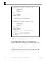
Two functions, vme_write and vme_read, provide access to VME dual-port memory in the
target DLAN module from the module where the program executes. The implementations of
these functions for a given execution environment will depend on the hardware that
environment provides for VMEbus access. In DLANINIT.C, implementations for a Series
90-70 PCM are shown. See Set_vme_ctl in the PCM C Function Library Reference
Manual, GFK-0772, for a complete discussion of VMEbus access from a Series 90-70 PCM.
The return types of vme_write and vme_read are declared int, and both return
NO_ERROR when successful. Actually, PCM code is currently unable to detect failures of
VMEbus read and write operations. However, some execution environments will provide this
information, and functions implemented for them would be able to return VME_ERROR when
appropriate.
GFK-1044A
Appendix A Example C Program to Initialize a VME DLAN Interface Module
A-3
A
ÁÁÁÁÁÁÁÁÁÁÁÁÁÁÁÁÁÁÁÁÁÁÁÁÁ
ÁÁÁÁÁÁÁÁÁÁÁÁÁÁÁÁÁÁÁÁÁÁÁÁÁ
ÁÁÁÁÁÁÁÁÁÁÁÁÁÁÁÁÁÁÁÁÁÁÁÁÁ
ÁÁÁÁÁÁÁÁÁÁÁÁÁÁÁÁÁÁÁÁÁÁÁÁÁ
ÁÁÁÁÁÁÁÁÁÁÁÁÁÁÁÁÁÁÁÁÁÁÁÁÁ
ÁÁÁÁÁÁÁÁÁÁÁÁÁÁÁÁÁÁÁÁÁÁÁÁÁ
ÁÁÁÁÁÁÁÁÁÁÁÁÁÁÁÁÁÁÁÁÁÁÁÁÁ
ÁÁÁÁÁÁÁÁÁÁÁÁÁÁÁÁÁÁÁÁÁÁÁÁÁ
ÁÁÁÁÁÁÁÁÁÁÁÁÁÁÁÁÁÁÁÁÁÁÁÁÁ
ÁÁÁÁÁÁÁÁÁÁÁÁÁÁÁÁÁÁÁÁÁÁÁÁÁ
ÁÁÁÁÁÁÁÁÁÁÁÁÁÁÁÁÁÁÁÁÁÁÁÁÁ
ÁÁÁÁÁÁÁÁÁÁÁÁÁÁÁÁÁÁÁÁÁÁÁÁÁ
ÁÁÁÁÁÁÁÁÁÁÁÁÁÁÁÁÁÁÁÁÁÁÁÁÁ
ÁÁÁÁÁÁÁÁÁÁÁÁÁÁÁÁÁÁÁÁÁÁÁÁÁ
ÁÁÁÁÁÁÁÁÁÁÁÁÁÁÁÁÁÁÁÁÁÁÁÁÁ
ÁÁÁÁÁÁÁÁÁÁÁÁÁÁÁÁÁÁÁÁÁÁÁÁÁ
ÁÁÁÁÁÁÁÁÁÁÁÁÁÁÁÁÁÁÁÁÁÁÁÁÁ
ÁÁÁÁÁÁÁÁÁÁÁÁÁÁÁÁÁÁÁÁÁÁÁÁÁ
ÁÁÁÁÁÁÁÁÁÁÁÁÁÁÁÁÁÁÁÁÁÁÁÁÁ
ÁÁÁÁÁÁÁÁÁÁÁÁÁÁÁÁÁÁÁÁÁÁÁÁÁ
ÁÁÁÁÁÁÁÁÁÁÁÁÁÁÁÁÁÁÁÁÁÁÁÁÁ
ÁÁÁÁÁÁÁÁÁÁÁÁÁÁÁÁÁÁÁÁÁÁÁÁÁ
ÁÁÁÁÁÁÁÁÁÁÁÁÁÁÁÁÁÁÁÁÁÁÁÁÁ
ÁÁÁÁÁÁÁÁÁÁÁÁÁÁÁÁÁÁÁÁÁÁÁÁÁ
ÁÁÁÁÁÁÁÁÁÁÁÁÁÁÁÁÁÁÁÁÁÁÁÁÁ
ÁÁÁÁÁÁÁÁÁÁÁÁÁÁÁÁÁÁÁÁÁÁÁÁÁ
ÁÁÁÁÁÁÁÁÁÁÁÁÁÁÁÁÁÁÁÁÁÁÁÁÁ
/*
* The implementation shown below assumes a GE Fanuc Series 90–70 PCM.
*/
int vme_write( unsigned short vme_hi,
unsigned short vme_lo,
void far* src,
int len,
unsigned char am )
{
int i;
unsigned short far* p;
unsigned short far* q = src;
FP_SEG( p ) = VME_WIN_SEG;
FP_OFF( p ) = vme_lo;
Set_vme_ctl( vme_hi, am );
for (i = len/2; i > 0; ––i) {
/* copy the data word by word */
*(p++) = *(q++);
}
if (len % 2) {
/* len is odd; copy the last byte */
*((unsigned char far*)p) = *((unsigned char far*)q);
}
return( NO_ERROR );
}
/*
* The implementation shown below assumes a GE Fanuc Series 90–70 PCM.
*/
int vme_read(
void far* dest,
unsigned short vme_hi,
unsigned short vme_lo,
int len,
unsigned char am )
{
int i;
unsigned short far* p;
unsigned short far* q = dest;
FP_SEG( p ) = VME_WIN_SEG;
FP_OFF( p ) = vme_lo;
Set_vme_ctl( vme_hi, am );
for (i = len/2; i > 0; ––i) {
/* copy the data word by word */
*(q++) = *(p++);
}
if (len % 2) {
/* len is odd; copy the last byte */
*((unsigned char far*)q) = *((unsigned char far*)p);
}
return( NO_ERROR );
}
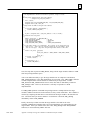
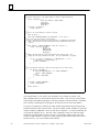
The implementation of vme_setup is intended to be as portable as possible. First, the rack
and slot parameter are checked for out-of-bounds values. The minimum and maximum
acceptable values are defined in DLANINIT.H.
Next, vme_setup calculates the standard access mode starting address and short
non-privileged address modifier code assigned to the rack/slot location of the target module,
based on the Series 90-70 conventions. These conventions are detailed in the Series 90-70
Programmable Controller User’s Guide to Integration of 3rd Party VME Modules, GFK-0488.
The rules for calculating start address and address modifier values appear immediately ahead of
the code that initializes the setup_data array. Note that the least significant 16 bits of every
module’s standard mode starting address must be zero. Only the byte containing bits 16
through 23 is calculated.
After setup_data is initialized, the last byte of the setup data area in the module’s VME
dual-ported memory is read using short non-privileged mode. The value in this byte must be
zero before the module may be initialized.
A-4
VME DLAN/DLAN+ Interface Module User’s Manual - August 1995
GFK-1044A
A
ÁÁÁÁÁÁÁÁÁÁÁÁÁÁÁÁÁÁÁÁÁÁÁÁÁ
ÁÁÁÁÁÁÁÁÁÁÁÁÁÁÁÁÁÁÁÁÁÁÁÁÁ
ÁÁÁÁÁÁÁÁÁÁÁÁÁÁÁÁÁÁÁÁÁÁÁÁÁ
ÁÁÁÁÁÁÁÁÁÁÁÁÁÁÁÁÁÁÁÁÁÁÁÁÁ
ÁÁÁÁÁÁÁÁÁÁÁÁÁÁÁÁÁÁÁÁÁÁÁÁÁ
ÁÁÁÁÁÁÁÁÁÁÁÁÁÁÁÁÁÁÁÁÁÁÁÁÁ
ÁÁÁÁÁÁÁÁÁÁÁÁÁÁÁÁÁÁÁÁÁÁÁÁÁ
ÁÁÁÁÁÁÁÁÁÁÁÁÁÁÁÁÁÁÁÁÁÁÁÁÁ
ÁÁÁÁÁÁÁÁÁÁÁÁÁÁÁÁÁÁÁÁÁÁÁÁÁ
ÁÁÁÁÁÁÁÁÁÁÁÁÁÁÁÁÁÁÁÁÁÁÁÁÁ
ÁÁÁÁÁÁÁÁÁÁÁÁÁÁÁÁÁÁÁÁÁÁÁÁÁ
ÁÁÁÁÁÁÁÁÁÁÁÁÁÁÁÁÁÁÁÁÁÁÁÁÁ
ÁÁÁÁÁÁÁÁÁÁÁÁÁÁÁÁÁÁÁÁÁÁÁÁÁ
ÁÁÁÁÁÁÁÁÁÁÁÁÁÁÁÁÁÁÁÁÁÁÁÁÁ
ÁÁÁÁÁÁÁÁÁÁÁÁÁÁÁÁÁÁÁÁÁÁÁÁÁ
ÁÁÁÁÁÁÁÁÁÁÁÁÁÁÁÁÁÁÁÁÁÁÁÁÁ
ÁÁÁÁÁÁÁÁÁÁÁÁÁÁÁÁÁÁÁÁÁÁÁÁÁ
ÁÁÁÁÁÁÁÁÁÁÁÁÁÁÁÁÁÁÁÁÁÁÁÁÁ
ÁÁÁÁÁÁÁÁÁÁÁÁÁÁÁÁÁÁÁÁÁÁÁÁÁ
ÁÁÁÁÁÁÁÁÁÁÁÁÁÁÁÁÁÁÁÁÁÁÁÁÁ
ÁÁÁÁÁÁÁÁÁÁÁÁÁÁÁÁÁÁÁÁÁÁÁÁÁ
ÁÁÁÁÁÁÁÁÁÁÁÁÁÁÁÁÁÁÁÁÁÁÁÁÁ
ÁÁÁÁÁÁÁÁÁÁÁÁÁÁÁÁÁÁÁÁÁÁÁÁÁ
ÁÁÁÁÁÁÁÁÁÁÁÁÁÁÁÁÁÁÁÁÁÁÁÁÁ
/*
* The implementation shown below should be portable, except as noted.
*/
int vme_setup( unsigned short short_base_address,
unsigned long std_base_address )
{
int i, status;
unsigned char setup_data[VME_DATA_LEN], read_data[VME_DATA_LEN];
unsigned char hi_adr, short_am;
/*
* Range check the VME std non–priv base address.
*/
if (std_base_address & 0xff00ffffL) {
return( INVALID_STD_ADDR );
}
hi_adr = (unsigned char )((std_base_address >> 16L) & 0x00ff);
/*
* Initialize the setup data.
*/
memset( setup_data, 0, VME_DATA_LEN );
setup_data[HI_ADR_OFFSET]
= hi_adr;
setup_data[AM_OFFSET]
= STD_NP_AM;
setup_data[MOD_TYPE_OFFSET]
= 0x80;
setup_data[DATA_AVAIL_OFFSET]
= CONFIG_DATA_AVAILABLE;
/*
* Is the module ready to be configured? All 64 bytes of the setup data area
*
must be zero. Since they are cleared starting at the low address, check
*
just the last byte. Only short non–privileged mode works at this time.
*/
status = vme_read( read_data,
0,
short_base_address + SETUP_OFFSET + DATA_AVAIL_OFFSET,
1,
short_am );
if (status != NO_ERROR ) {
return( status );
}
if (*read_data != 0) {
return( VME_ERROR );
}
Next, the setup data is passed to vme_write, along with the target module’s address in VME
short non-privileged address space.
After a ten millisecond delay to give the target module time to complete its initialization,
vme_setup attempts to verify that initialization was successful. First, vme_read is called to
read the setup data back from the module in standard non-privileged mode. If either
vme_write or vme_read returned an error status, that status is immediately returned to
vme_setup’s caller. However, this outcome is currently not possible in a PCM
implementation.
If a vme_read operation in standard non-privileged mode is attempted before the target
module’s VMEbus interface has been initialized, it always reads invalid data. This condition is
detected by comparing the data that was read back from the target module to the data that was
sent. All but the last byte must be identical. If a difference is detected, vme_setup
immediately returns VME_ERROR.
Finally, the last byte of data read from the target module is checked for the value
CONFIG_COMPLETE, indicating that a successful initialization was acknowledged by the
target module. If the byte contains some other value, vme_setup returns INIT_ERROR.
Otherwise, it returns SETUP_CMPLT and exits.
GFK-1044A
Appendix A Example C Program to Initialize a VME DLAN Interface Module
A-5
A
ÁÁÁÁÁÁÁÁÁÁÁÁÁÁÁÁÁÁÁÁÁÁÁÁÁ
ÁÁÁÁÁÁÁÁÁÁÁÁÁÁÁÁÁÁÁÁÁÁÁÁÁ
ÁÁÁÁÁÁÁÁÁÁÁÁÁÁÁÁÁÁÁÁÁÁÁÁÁ
ÁÁÁÁÁÁÁÁÁÁÁÁÁÁÁÁÁÁÁÁÁÁÁÁÁ
ÁÁÁÁÁÁÁÁÁÁÁÁÁÁÁÁÁÁÁÁÁÁÁÁÁ
ÁÁÁÁÁÁÁÁÁÁÁÁÁÁÁÁÁÁÁÁÁÁÁÁÁ
ÁÁÁÁÁÁÁÁÁÁÁÁÁÁÁÁÁÁÁÁÁÁÁÁÁ
ÁÁÁÁÁÁÁÁÁÁÁÁÁÁÁÁÁÁÁÁÁÁÁÁÁ
ÁÁÁÁÁÁÁÁÁÁÁÁÁÁÁÁÁÁÁÁÁÁÁÁÁ
ÁÁÁÁÁÁÁÁÁÁÁÁÁÁÁÁÁÁÁÁÁÁÁÁÁ
ÁÁÁÁÁÁÁÁÁÁÁÁÁÁÁÁÁÁÁÁÁÁÁÁÁ
ÁÁÁÁÁÁÁÁÁÁÁÁÁÁÁÁÁÁÁÁÁÁÁÁÁ
ÁÁÁÁÁÁÁÁÁÁÁÁÁÁÁÁÁÁÁÁÁÁÁÁÁ
ÁÁÁÁÁÁÁÁÁÁÁÁÁÁÁÁÁÁÁÁÁÁÁÁÁ
ÁÁÁÁÁÁÁÁÁÁÁÁÁÁÁÁÁÁÁÁÁÁÁÁÁ
ÁÁÁÁÁÁÁÁÁÁÁÁÁÁÁÁÁÁÁÁÁÁÁÁÁ
ÁÁÁÁÁÁÁÁÁÁÁÁÁÁÁÁÁÁÁÁÁÁÁÁÁ
ÁÁÁÁÁÁÁÁÁÁÁÁÁÁÁÁÁÁÁÁÁÁÁÁÁ
ÁÁÁÁÁÁÁÁÁÁÁÁÁÁÁÁÁÁÁÁÁÁÁÁÁ
ÁÁÁÁÁÁÁÁÁÁÁÁÁÁÁÁÁÁÁÁÁÁÁÁÁ
ÁÁÁÁÁÁÁÁÁÁÁÁÁÁÁÁÁÁÁÁÁÁÁÁÁ
ÁÁÁÁÁÁÁÁÁÁÁÁÁÁÁÁÁÁÁÁÁÁÁÁÁ
ÁÁÁÁÁÁÁÁÁÁÁÁÁÁÁÁÁÁÁÁÁÁÁÁÁ
ÁÁÁÁÁÁÁÁÁÁÁÁÁÁÁÁÁÁÁÁÁÁÁÁÁ
ÁÁÁÁÁÁÁÁÁÁÁÁÁÁÁÁÁÁÁÁÁÁÁÁÁ
ÁÁÁÁÁÁÁÁÁÁÁÁÁÁÁÁÁÁÁÁÁÁÁÁÁ
ÁÁÁÁÁÁÁÁÁÁÁÁÁÁÁÁÁÁÁÁÁÁÁÁÁ
ÁÁÁÁÁÁÁÁÁÁÁÁÁÁÁÁÁÁÁÁÁÁÁÁÁ
ÁÁÁÁÁÁÁÁÁÁÁÁÁÁÁÁÁÁÁÁÁÁÁÁÁ
ÁÁÁÁÁÁÁÁÁÁÁÁÁÁÁÁÁÁÁÁÁÁÁÁÁ
ÁÁÁÁÁÁÁÁÁÁÁÁÁÁÁÁÁÁÁÁÁÁÁÁÁ
ÁÁÁÁÁÁÁÁÁÁÁÁÁÁÁÁÁÁÁÁÁÁÁÁÁ
/*
* Send the setup data to the target module in short non–privileged mode.
*/
status = vme_write( 0,
short_base_address + SETUP_OFFSET,
setup_data,
VME_DATA_LEN,
short_am );
if (status != NO_ERROR) {
return( status );
}
/*
* Start a one second timeout to wait for success.
*/
Reset_ef( EF_00 );
Start_timer( RELATIVE_TIMEOUT, MS_COUNT_MODE, 0, 1000, EF_00 );
/*
* In a loop, wait for success or the timeout.
* Read the setup data back from the target module in standard non–privileged
*
mode. The read will return invalid data if the initialization did not
*
succeed.
*/
while (status != CONFIG_COMPLETE && !(Test_ef() & EF_00)) {
status = vme_read( read_data,
hi_adr,
SETUP_OFFSET,
VME_DATA_LEN,
STD_NP_AM );
/*
* Compare the data that was read back with the data that was sent. All
*
except the last byte should be the same. If one is different, try again.
*/
for (i = 0; status == NO_ERROR && i < VME_DATA_LEN – 1; ++i) {
if (read_data[i] != setup_data[i]) {
status = VME_ERROR;
}
}
/*
* If good data was read back, check the last byte for the correct value.
*/
if (status == NO_ERROR) {
if (read_data[VME_DATA_LEN – 1] == CONFIG_COMPLETE) {
status = CONFIG_COMPLETE;
} else {
status = INIT_ERROR;
}
}
}
if (status == CONFIG_COMPLETE) {
status = SETUP_CMPLT;
}
return( status );
}
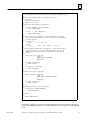
The implementation of vme_status is also intended to be as portable as possible. First,
vme_status checks for out-of-bounds rack and slot values. Next, one byte of the standard
non-privileged start address appropriate for the target module’s rack/slot location is calculated.
This is the byte containing bits 16 through 23, the only non-zero bits of the start address.
Two bytes of setup data are read from the target module using standard non-privileged mode
and then checked for their expected values. The byte at DATA_AVAIL_OFFSET is expected to
contain CONFIG_COMPLETE. However, that value is defined as –1, or 0FF hexadecimal, the
value when all eight bits are set. The same value is obtained in some cases when the target
module has not been initialized or does not exist. Consequently, another value is also read.
The byte at AM_OFFSET is expected to contain STD_NP_AM, which contains four zero bits
and four one bits. It is a more reliable status indicator.
A-6
VME DLAN/DLAN+ Interface Module User’s Manual - August 1995
GFK-1044A
A
ÁÁÁÁÁÁÁÁÁÁÁÁÁÁÁÁÁÁÁÁÁÁÁÁÁ
ÁÁÁÁÁÁÁÁÁÁÁÁÁÁÁÁÁÁÁÁÁÁÁÁÁ
ÁÁÁÁÁÁÁÁÁÁÁÁÁÁÁÁÁÁÁÁÁÁÁÁÁ
ÁÁÁÁÁÁÁÁÁÁÁÁÁÁÁÁÁÁÁÁÁÁÁÁÁ
ÁÁÁÁÁÁÁÁÁÁÁÁÁÁÁÁÁÁÁÁÁÁÁÁÁ
ÁÁÁÁÁÁÁÁÁÁÁÁÁÁÁÁÁÁÁÁÁÁÁÁÁ
ÁÁÁÁÁÁÁÁÁÁÁÁÁÁÁÁÁÁÁÁÁÁÁÁÁ
ÁÁÁÁÁÁÁÁÁÁÁÁÁÁÁÁÁÁÁÁÁÁÁÁÁ
ÁÁÁÁÁÁÁÁÁÁÁÁÁÁÁÁÁÁÁÁÁÁÁÁÁ
ÁÁÁÁÁÁÁÁÁÁÁÁÁÁÁÁÁÁÁÁÁÁÁÁÁ
ÁÁÁÁÁÁÁÁÁÁÁÁÁÁÁÁÁÁÁÁÁÁÁÁÁ
ÁÁÁÁÁÁÁÁÁÁÁÁÁÁÁÁÁÁÁÁÁÁÁÁÁ
ÁÁÁÁÁÁÁÁÁÁÁÁÁÁÁÁÁÁÁÁÁÁÁÁÁ
ÁÁÁÁÁÁÁÁÁÁÁÁÁÁÁÁÁÁÁÁÁÁÁÁÁ
ÁÁÁÁÁÁÁÁÁÁÁÁÁÁÁÁÁÁÁÁÁÁÁÁÁ
ÁÁÁÁÁÁÁÁÁÁÁÁÁÁÁÁÁÁÁÁÁÁÁÁÁ
ÁÁÁÁÁÁÁÁÁÁÁÁÁÁÁÁÁÁÁÁÁÁÁÁÁ
ÁÁÁÁÁÁÁÁÁÁÁÁÁÁÁÁÁÁÁÁÁÁÁÁÁ
ÁÁÁÁÁÁÁÁÁÁÁÁÁÁÁÁÁÁÁÁÁÁÁÁÁ
ÁÁÁÁÁÁÁÁÁÁÁÁÁÁÁÁÁÁÁÁÁÁÁÁÁ
ÁÁÁÁÁÁÁÁÁÁÁÁÁÁÁÁÁÁÁÁÁÁÁÁÁ
ÁÁÁÁÁÁÁÁÁÁÁÁÁÁÁÁÁÁÁÁÁÁÁÁÁ
ÁÁÁÁÁÁÁÁÁÁÁÁÁÁÁÁÁÁÁÁÁÁÁÁÁ
ÁÁÁÁÁÁÁÁÁÁÁÁÁÁÁÁÁÁÁÁÁÁÁÁÁ
ÁÁÁÁÁÁÁÁÁÁÁÁÁÁÁÁÁÁÁÁÁÁÁÁÁ
ÁÁÁÁÁÁÁÁÁÁÁÁÁÁÁÁÁÁÁÁÁÁÁÁÁ
ÁÁÁÁÁÁÁÁÁÁÁÁÁÁÁÁÁÁÁÁÁÁÁÁÁ
ÁÁÁÁÁÁÁÁÁÁÁÁÁÁÁÁÁÁÁÁÁÁÁÁÁ
ÁÁÁÁÁÁÁÁÁÁÁÁÁÁÁÁÁÁÁÁÁÁÁÁÁ
ÁÁÁÁÁÁÁÁÁÁÁÁÁÁÁÁÁÁÁÁÁÁÁÁÁ
ÁÁÁÁÁÁÁÁÁÁÁÁÁÁÁÁÁÁÁÁÁÁÁÁÁ
ÁÁÁÁÁÁÁÁÁÁÁÁÁÁÁÁÁÁÁÁÁÁÁÁÁ
ÁÁÁÁÁÁÁÁÁÁÁÁÁÁÁÁÁÁÁÁÁÁÁÁÁ
ÁÁÁÁÁÁÁÁÁÁÁÁÁÁÁÁÁÁÁÁÁÁÁÁÁ
ÁÁÁÁÁÁÁÁÁÁÁÁÁÁÁÁÁÁÁÁÁÁÁÁÁ
ÁÁÁÁÁÁÁÁÁÁÁÁÁÁÁÁÁÁÁÁÁÁÁÁÁ
ÁÁÁÁÁÁÁÁÁÁÁÁÁÁÁÁÁÁÁÁÁÁÁÁÁ
ÁÁÁÁÁÁÁÁÁÁÁÁÁÁÁÁÁÁÁÁÁÁÁÁÁ
/*
* The implementation shown below should also be portable, except as noted.
*/
int vme_status( unsigned short rack, unsigned short slot )
{
int status;
unsigned char read_data;
unsigned char hi_adr;
/*
* Range check the rack and slot parameters.
*/
if (rack < MIN_RACK || rack > MAX_RACK) {
return( INVALID_RACK );
}
if (slot < 2 || slot > MAX_SLOT) {
return( INVALID_SLOT);
}
/*
* This is Series 90–70 convention for the standard mode base address
*
based on the module’s rack/slot location. Modify it as appropriate
*
for other systems.
*/
if (rack == 0) {
hi_adr
= 2 * (slot – 2);
} else {
hi_adr
= 0xF0 – (0x10 * rack) + 2 * (slot – 2);
}
/*
* Read the address modifier byte of setup data. It has some zero bits
*
and some non–zero bits, so values with all bits zero or one (the
*
likely cases before standard non–privileged mode is enabled) are
*
invalid.
*/
status = vme_read( &read_data,
hi_adr,
SETUP_OFFSET + AM_OFFSET,
1,
STD_NP_AM );
if (status != NO_ERROR) {
return( status );
}
if (read_data != STD_NP_AM) {
return( VME_ERROR );
}
/*
* Read the last byte of setup data.
*/
status = vme_read( &read_data,
hi_adr,
SETUP_OFFSET + DATA_AVAIL_OFFSET,
1,
STD_NP_AM );
if (status != NO_ERROR) {
return( status );
}
/*
* Check the last byte for the correct value.
*/
if (read_data != CONFIG_COMPLETE) {
return( INIT_ERROR );
}
/*
* Success!
*/
return( SETUP_CMPLT );
}
If both bytes contain the expected values, vme_status returns SETUP_CMPLT; otherwise, it
returns INIT_ERROR when the byte at AM_OFFSET has the expected value, or VME_ERROR
if not.
GFK-1044A
Appendix A Example C Program to Initialize a VME DLAN Interface Module
A-7
Index
A
Acknowledgement, reading the, 2-9
Address select jumpers, 1-4
Addressing target VME DLAN module, 2-9
Appendix A, Example C program to initialize
a VME DLAN interface module, A-1
Applications, VME DLAN
description of, 1-2
hardware requirements, 1-2
B
Battery (not used), 1-5
BEM764, initialization, 2-8
from a C program, A-1
module acknowledgment, 2-9
C
COMMAND OUT LED, 1-4
Configuring DLAN jumpers, 2-5
Configuring the VME DLAN module, with
Logicmaster 90 software, 2-8
Connectors, serial (not used), 1-5
D
E
Example C program to initialize a BEM764,
A-1
F
Functional overview, DLAN operation, 1-1
H
Hardware
address select jumpers, 1-4
COMMAND OUT LED, 1-4
DATA IN LED, 1-4
DLAN configuration jumpers, 1-5
DLAN network connector, 1-5
installing a VME DLAN module, 2-3
installing the VME DLAN hardware, 2-2
LED indicators, 1-3
MODULE OK LED, 1-4
restart pushbutton, 1-4
VME DLAN/DLAN+ interface module
description, 1-3
watchdog timer, 1-4
what you will need, 2-1
I
DATA IN LED, 1-4
ID string, module, 2-10
DLAN Configuration Jumpers, 1-5
Initialization, 2-8
from a C program, A-1
module acknowledgment, 2-9
process described, 2-9
required data, 2-8
DLAN jumper configuration, 2-5
DLAN module, configuration jumpers, 1-5
DLAN network connector, 1-5
DLAN network type, selecting, 2-6
DLAN operation, 1-1
DLAN/DLAN+ interface module
address select jumpers, 1-4
DLAN configuration jumpers, 2-5
DLAN network connector, 1-5
LED indicators, 1-3
COMMAND OUT, 1-4
DATA IN, 1-4
MODULE OK, 1-4
restart pushbutton, 1-4
GFK-1044A
watchdog timer, 1-4
Initialization and installation, 2-1
Initialization data, required, 2-8
Initialization data, writing, 2-9
Installation and initialization, 2-1
Installing the VME DLAN module
configuring the VME DLAN module with
Logicmaster 90 software, 2-8
module location in rack, 2-2
procedures, 2-3
setting address select jumpers, 2-2
setting DLAN configuration jumpers, 2-5
Index-1
Index
VME DLAN hardware, 2-2
what you will need, 2-1
Installing the VME module, 2-1
J
P
Power-up diagnostics result, 2-10
R
Jumper configuration, DLAN, 2-5
Reading the DLAN modules’
acknowledgement, 2-9
Jumpers, address select, 1-4
Required inilization data, 2-8
Jumpers, DLAN configuration, 1-5
Restart pushbutton, 1-4
RS-485 termination resistors, 2-6
L
S
LED indicators, 1-3
on Series 90-70 PCM, 1-3
Selecting DLAN network type, 2-6
Logicmaster 90 software, 2-8
Selecting RS-485 termination resistors, 2-6
Serial connectors (not used), 1-5
M
Module access, short non-privileged mode,
2-9
Module description
address select jumpers, 1-4
COMMAND OUT LED, 1-4
DATA IN LED, 1-4
DLAN configuration jumpers, 1-5
DLAN network connector, 1-5
LED indicators, 1-3
MODULE OK LED, 1-4
restart pushbutton, 1-4
watchdog timer, 1-4
Status data
daughter board ID code, 2-10
module error code, 2-10
module ID string, 2-10
power-up diagnostics result, 2-10
System overview, 1-1
V
Module ID string, 2-10
VME
module access, short non-privileged mode,
2-9
module start address, standard
non-privileged mode, 2-8
MODULE OK LED, 1-4
VME DLAN applications, 1-2
Module start address, standard non-privileged
mode, 2-8
N
Network connector, DLAN, 1-5
Network type jumpers, 2-6
O
Overview, system, 1-1
Index-2
Setup data, required, 2-8
VME DLAN interface module, functions, 1-2
VME DLAN module
dual-ported memory, 2-8
initialization
process described, 2-9
required data, 2-8
status data
daughter board ID code, 2-10
module error code, 2-10
module ID string, 2-10
power-up diagnostic result, 2-10
VME memory, 2-8
VME DLAN/DLAN+ module description,
1-3
GFK-1044A
Index
W
Watchdog timer, 1-4
Writing initialization data, 2-9
GFK-1044A
Index-3