1
Smart Transmitter Interface Products
(HARTr Protocol)
Cat. Nos. 1770-HT1, 1770-HT8, 1770-HT16
User Manual
Important User Information
Because of the variety of uses for the products described in this publication,
those responsible for the application and use of this control equipment must
satisfy themselves that all necessary steps have been taken to assure that each
application and use meets all performance and safety requirements, including
any applicable laws, regulations, codes and standards.
The illustrations, charts, sample programs and layout examples shown in this
guide are intended solely for purposes of example. Since there are many
variables and requirements associated with any particular installation, the
Allen-Bradley Company, Inc. does not assume responsibility or liability (to
include intellectual property liability) for actual use based upon the examples
shown in this publication.
Allen-Bradley Publication SGI-1.1, “Safety Guidelines for the Application,
Installation and Maintenance of Solid State Control” (available from your local
Allen-Bradley office) describes some important differences between solid-state
equipment and electromechanical devices which should be taken into
consideration when applying products such as those described in this
publication.
Reproduction of the contents of this copyrighted manual, in whole or in part,
without written permission of the Allen-Bradley Company Inc. is prohibited.
Throughout this manual we use notes to make you aware of safety
considerations:
ATTENTION: Identifies information about practices or
circumstances that can lead to personal injury or death, property
damage or economic loss.
Attentions help you:
identify a hazard
avoid the hazard
recognize the consequences
Important: Identifies information that is especially important for
successful application and understanding of the product.
Interchange, ControlView, Data Highway Plus and DH+ are trademarks and PLC is a registered
trademark of Allen-Bradley Company, Inc.
HART is a registered trademark of Rosemount Inc.
IBM is a registered trademark of International Business Machines Corporation.
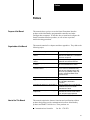
Table of Contents
Preface . . . . . . . . . . . . . . . . . . . . . . . . . . . . . . . . . . . . . . .
P1
Purpose of the Manual . . . . . . . . . . . . . . . . . . . . . . . . . . . . . . . .
Organization of the Manual . . . . . . . . . . . . . . . . . . . . . . . . . . . . .
How to Use This Manual . . . . . . . . . . . . . . . . . . . . . . . . . . . . . . .
Audience . . . . . . . . . . . . . . . . . . . . . . . . . . . . . . . . . . . . . . . .
Related Publications . . . . . . . . . . . . . . . . . . . . . . . . . . . . . . . . . .
AllenBradley Publications . . . . . . . . . . . . . . . . . . . . . . . . . . .
HART Publications . . . . . . . . . . . . . . . . . . . . . . . . . . . . . . . . .
Related Products . . . . . . . . . . . . . . . . . . . . . . . . . . . . . . . . . . . .
Glossary of Terms and Abbreviations . . . . . . . . . . . . . . . . . . . . . .
P1
P1
P1
P2
P2
P2
P2
P3
P3
Introducing the Smart Transmitter Interface . . . . . . . . . . . .
11
Product Overview . . . . . . . . . . . . . . . . . . . . . . . . . . . . . . . . . . .
1770HT1 Communications Controller . . . . . . . . . . . . . . . . . . .
1770HT8/16 Terminal Block . . . . . . . . . . . . . . . . . . . . . . . . . .
The Remote I/O Port of the Communications Controller . . . . . . .
The RS232C Port of the Communications Controller . . . . . . . .
The HART Protocol . . . . . . . . . . . . . . . . . . . . . . . . . . . . . . . . . .
The HART Protocol and the Smart Transmitter Interface . . . . . .
Poll/Response Mode . . . . . . . . . . . . . . . . . . . . . . . . . . . . . . .
Burst Mode . . . . . . . . . . . . . . . . . . . . . . . . . . . . . . . . . . . . . .
Features of the Smart Transmitter Interface . . . . . . . . . . . . . . . . .
Benefits of Using the Smart Transmitter Interface . . . . . . . . . . . . .
Compatibility . . . . . . . . . . . . . . . . . . . . . . . . . . . . . . . . . . . . . . .
PLC5 Family . . . . . . . . . . . . . . . . . . . . . . . . . . . . . . . . . . . . .
HART Field Devices . . . . . . . . . . . . . . . . . . . . . . . . . . . . . . . .
Analog I/O Devices . . . . . . . . . . . . . . . . . . . . . . . . . . . . . . . . .
Hand Held Terminal . . . . . . . . . . . . . . . . . . . . . . . . . . . . . . . .
11
11
13
14
15
18
19
110
110
110
111
112
112
112
113
113
Installing the Smart Transmitter Interface Products . . . . . .
21
Before You Begin . . . . . . . . . . . . . . . . . . . . . . . . . . . . . . . . . . . .
Electrostatic Damage . . . . . . . . . . . . . . . . . . . . . . . . . . . . . . . . .
Overview of the Installation Procedure . . . . . . . . . . . . . . . . . . . . .
Mounting Smart Transmitter Interface Products in a Cabinet . . . . .
Connecting the Communications Controller to the Terminal Blocks .
Digital Communications Cables . . . . . . . . . . . . . . . . . . . . . . . .
Linear Connection . . . . . . . . . . . . . . . . . . . . . . . . . . . . . . . . .
Star Connection . . . . . . . . . . . . . . . . . . . . . . . . . . . . . . . . . . .
Star/Linear Connection . . . . . . . . . . . . . . . . . . . . . . . . . . . . . .
Connector and Pinout . . . . . . . . . . . . . . . . . . . . . . . . . . . . . . .
Setting the Board Address Jumpers . . . . . . . . . . . . . . . . . . . . . . .
21
22
22
23
24
24
25
26
27
28
29
ii
Table of Contents
Marking the Terminal Block Labels . . . . . . . . . . . . . . . . . . . . . .
Connecting the Terminal Blocks to I/O and HART Field Devices . . .
Connecting to 1771 I/O Devices . . . . . . . . . . . . . . . . . . . . . . .
Connecting to HART Field Devices . . . . . . . . . . . . . . . . . . . . .
Connecting a Hand Held Terminal . . . . . . . . . . . . . . . . . . . . . .
Grounding . . . . . . . . . . . . . . . . . . . . . . . . . . . . . . . . . . . . . . . . .
Grounding the HART Field Device Cable Shield . . . . . . . . . . . .
Grounding the Analog I/O Cable Shield . . . . . . . . . . . . . . . . . .
Supplying Power to the Communications Controller and
Terminal Blocks . . . . . . . . . . . . . . . . . . . . . . . . . . . . . . . . . .
Fuses for the Communications Controller . . . . . . . . . . . . . . . . .
Connecting Power to the Communications Controller . . . . . . . . .
Supplying Loop Power for HART Field Devices . . . . . . . . . . . . . . .
Power Supply Requirements . . . . . . . . . . . . . . . . . . . . . . . . . .
Connecting the Power Supply for Loop Power . . . . . . . . . . . . .
Connecting the Communications Controller to the RIO Host . . . . . .
Termination . . . . . . . . . . . . . . . . . . . . . . . . . . . . . . . . . . . . . .
Activity Indicator . . . . . . . . . . . . . . . . . . . . . . . . . . . . . . . . . . .
Connecting the Communications Controller to the RS232C Host . .
RS232C Baud Rates . . . . . . . . . . . . . . . . . . . . . . . . . . . . . . .
Cables . . . . . . . . . . . . . . . . . . . . . . . . . . . . . . . . . . . . . . . . .
Activity Indicator . . . . . . . . . . . . . . . . . . . . . . . . . . . . . . . . . . .
Connector and Pinout . . . . . . . . . . . . . . . . . . . . . . . . . . . . . . .
Modem Connections . . . . . . . . . . . . . . . . . . . . . . . . . . . . . . .
211
211
212
213
216
218
218
218
219
219
220
220
221
221
222
223
224
224
224
224
224
224
229
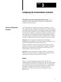
Configuring the Communications Controller . . . . . . . . . . .
31
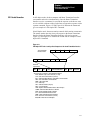
Overview of Configuration Procedures . . . . . . . . . . . . . . . . . . . . .
Displays . . . . . . . . . . . . . . . . . . . . . . . . . . . . . . . . . . . . . . . .
Push Buttons . . . . . . . . . . . . . . . . . . . . . . . . . . . . . . . . . . . . .
Configuration Step by Step . . . . . . . . . . . . . . . . . . . . . . . . . . . . .
Enter Configuration Mode . . . . . . . . . . . . . . . . . . . . . . . . . . . .
Configure Basic Parameters . . . . . . . . . . . . . . . . . . . . . . . . . .
Configure Advanced RS232C Parameters . . . . . . . . . . . . . . . .
Save and Exit . . . . . . . . . . . . . . . . . . . . . . . . . . . . . . . . . . . .
Exit Without Saving . . . . . . . . . . . . . . . . . . . . . . . . . . . . . . . .
Setting Factory Defaults . . . . . . . . . . . . . . . . . . . . . . . . . . . . .
Communication Parameters . . . . . . . . . . . . . . . . . . . . . . . . . . . .
Basic Parameters . . . . . . . . . . . . . . . . . . . . . . . . . . . . . . . . . .
Basic Parameters . . . . . . . . . . . . . . . . . . . . . . . . . . . . . . . . . .
Advanced RS232C Communication Parameters . . . . . . . . . . .
Verifying the Communication Parameters . . . . . . . . . . . . . . . . . . .
Marking the Communications Controller Label . . . . . . . . . . . . .
31
31
32
33
33
34
34
34
35
36
36
36
36
38
310
310
Table of Contents
iii
Communicating with the Smart Transmitter Interface . . . .
41
Data Routing and Protocol Conversion . . . . . . . . . . . . . . . . . . . . .
Data Routing In Poll and Response Mode . . . . . . . . . . . . . . . . .
Data Routing in Burst Monitor Mode . . . . . . . . . . . . . . . . . . . . .
Protocol Conversion . . . . . . . . . . . . . . . . . . . . . . . . . . . . . . . .
Definition of Terms . . . . . . . . . . . . . . . . . . . . . . . . . . . . . . . . . . .
HART Poll Packets . . . . . . . . . . . . . . . . . . . . . . . . . . . . . . . . . . .
Preamble . . . . . . . . . . . . . . . . . . . . . . . . . . . . . . . . . . . . . . .
HART Delimiter . . . . . . . . . . . . . . . . . . . . . . . . . . . . . . . . . . .
HART Address . . . . . . . . . . . . . . . . . . . . . . . . . . . . . . . . . . . .
HART Command . . . . . . . . . . . . . . . . . . . . . . . . . . . . . . . . . .
Byte Count . . . . . . . . . . . . . . . . . . . . . . . . . . . . . . . . . . . . . .
Data . . . . . . . . . . . . . . . . . . . . . . . . . . . . . . . . . . . . . . . . . . .
Check Byte . . . . . . . . . . . . . . . . . . . . . . . . . . . . . . . . . . . . . .
HART Response and Burst Data Packets . . . . . . . . . . . . . . . . . . .
Preamble . . . . . . . . . . . . . . . . . . . . . . . . . . . . . . . . . . . . . . .
HART Delimiter . . . . . . . . . . . . . . . . . . . . . . . . . . . . . . . . . . .
HART Address . . . . . . . . . . . . . . . . . . . . . . . . . . . . . . . . . . . .
HART Command . . . . . . . . . . . . . . . . . . . . . . . . . . . . . . . . . .
Byte Count . . . . . . . . . . . . . . . . . . . . . . . . . . . . . . . . . . . . . .
Response Code . . . . . . . . . . . . . . . . . . . . . . . . . . . . . . . . . . .
Data . . . . . . . . . . . . . . . . . . . . . . . . . . . . . . . . . . . . . . . . . . .
Check Byte . . . . . . . . . . . . . . . . . . . . . . . . . . . . . . . . . . . . . .
Smart Transmitter Interface Packets Received by the
Smart Transmitter Interface . . . . . . . . . . . . . . . . . . . . . . . . . .
Smart Transmitter Interface Command . . . . . . . . . . . . . . . . . . .
Smart Transmitter Interface Channel . . . . . . . . . . . . . . . . . . . .
Smart Transmitter Interface Control . . . . . . . . . . . . . . . . . . . . .
Smart Transmitter Interface Parameter . . . . . . . . . . . . . . . . . . .
Smart Transmitter Interface Data . . . . . . . . . . . . . . . . . . . . . . .
Smart Transmitter Interface Packets Sent by the Smart
Transmitter Interface . . . . . . . . . . . . . . . . . . . . . . . . . . . . . . .
Smart Transmitter Interface Command . . . . . . . . . . . . . . . . . . .
Smart Transmitter Interface Channel . . . . . . . . . . . . . . . . . . . .
Smart Transmitter Interface Error Code . . . . . . . . . . . . . . . . . .
Smart Transmitter Interface Status . . . . . . . . . . . . . . . . . . . . . .
Smart Transmitter Interface Data . . . . . . . . . . . . . . . . . . . . . . .
Valid Smart Transmitter Interface Commands and Responses . . . .
No Operation (hexadecimal command 00) . . . . . . . . . . . . . . . .
Enable Poll and Response Mode (hexadecimal command 01) . .
Enable Burst Monitor Mode (hexadecimal command 02) . . . . . .
Send Message to Device (hexadecimal command 10) . . . . . . . .
Read Burst Data (hexadecimal command 11) . . . . . . . . . . . . . .
Set Number of Preambles (hexadecimal command 20) . . . . . . .
Set Number of Retries (hexadecimal command 21) . . . . . . . . . .
41
42
42
43
44
45
45
45
45
48
48
49
49
49
49
49
410
411
411
412
413
413
414
414
414
415
416
416
416
416
417
417
417
419
419
420
420
420
420
421
421
422
iv
Table of Contents
Read Status and Statistics (hexadecimal command 30) . . . . . . .
Reset Statistics Counters (hexadecimal command 31) . . . . . . . .
Read ID (hexadecimal command 32) . . . . . . . . . . . . . . . . . . . .
Programmable Controller Communication with HART Field Devices
Short Frame Word Contents Programmable Controller to Smart
Transmitter Interface (Offset at D9:00) . . . . . . . . . . . . . . . .
Short Frame Word Contents Smart Transmitter Interface to
Programmable Controller (Offset at D9:40) . . . . . . . . . . . . .
Long Frame Word Contents Programmable Controller to Smart
Transmitter Interface (Offset at D9:10) . . . . . . . . . . . . . . . .
Long Frame Word Contents Smart Transmitter Interface to
Programmable Controller (Offset at D9:40) . . . . . . . . . . . . .
Serial Communication with the Smart Transmitter Interface . . . . . .
Full Duplex . . . . . . . . . . . . . . . . . . . . . . . . . . . . . . . . . . . . . .
Half Duplex . . . . . . . . . . . . . . . . . . . . . . . . . . . . . . . . . . . . . .
DF1 Packet Formation . . . . . . . . . . . . . . . . . . . . . . . . . . . . . . . .
Data Highway Plus and the Smart Transmitter Interface . . . . . . . . .
422
422
422
425
433
434
435
435
437
440
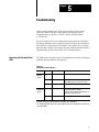
Troubleshooting . . . . . . . . . . . . . . . . . . . . . . . . . . . . . . . .
51
Interpreting the Terminal Block LEDs . . . . . . . . . . . . . . . . . . . . . .
Interpreting the Communications Controller Status LEDs . . . . . . . .
Interpreting the Communications Controller Status LEDs . . . . . .
Interpreting the Communications Controller Numeric Displays . . . .
51
52
52
53
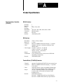
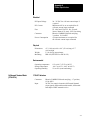
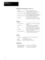
Product Specifications . . . . . . . . . . . . . . . . . . . . . . . . . . .
A1
Communications Controller (1770HT1) . . . . . . . . . . . . . . . . . . . .
RS232 Interface . . . . . . . . . . . . . . . . . . . . . . . . . . . . . . . . . .
RIO Interface . . . . . . . . . . . . . . . . . . . . . . . . . . . . . . . . . . . . .
Terminal Block (1770HT8/16) Interface . . . . . . . . . . . . . . . . . .
Electrical . . . . . . . . . . . . . . . . . . . . . . . . . . . . . . . . . . . . . . . .
Physical . . . . . . . . . . . . . . . . . . . . . . . . . . . . . . . . . . . . . . . .
Environmental . . . . . . . . . . . . . . . . . . . . . . . . . . . . . . . . . . . .
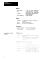
8 Channel Terminal Block (1770HT8) . . . . . . . . . . . . . . . . . . . . .
1770HT1 Interface . . . . . . . . . . . . . . . . . . . . . . . . . . . . . . . .
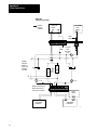
420 mA Current Loop Interfaces (see Figure A.1) . . . . . . . . . .
Electrical . . . . . . . . . . . . . . . . . . . . . . . . . . . . . . . . . . . . . . . .
Physical . . . . . . . . . . . . . . . . . . . . . . . . . . . . . . . . . . . . . . . .
Environmental . . . . . . . . . . . . . . . . . . . . . . . . . . . . . . . . . . . .
16 Channel Terminal Block (1770HT16) . . . . . . . . . . . . . . . . . . .
1770HT1 Interface . . . . . . . . . . . . . . . . . . . . . . . . . . . . . . . .
420 mA Current Loop Interfaces (see Figure A.1) . . . . . . . . . .
Electrical . . . . . . . . . . . . . . . . . . . . . . . . . . . . . . . . . . . . . . . .
Physical . . . . . . . . . . . . . . . . . . . . . . . . . . . . . . . . . . . . . . . .
Environmental . . . . . . . . . . . . . . . . . . . . . . . . . . . . . . . . . . . .
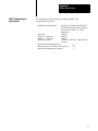
HART Communications Specifications . . . . . . . . . . . . . . . . . . . . .
A1
A1
A1
A1
A2
A2
A2
A2
A2
A2
A3
A3
A3
A3
A3
A4
A4
A4
A4
A5
428
430
431
Table of Contents
v
DF1 Diagnostic Command Support . . . . . . . . . . . . . . . . . .
B1
Diagnostic Command Support . . . . . . . . . . . . . . . . . . . . . . . . . . .
Diagnostic Loop . . . . . . . . . . . . . . . . . . . . . . . . . . . . . . . . . . .
Diagnostic Read . . . . . . . . . . . . . . . . . . . . . . . . . . . . . . . . . .
Diagnostic Status . . . . . . . . . . . . . . . . . . . . . . . . . . . . . . . . . .
Diagnostic Counter Reset . . . . . . . . . . . . . . . . . . . . . . . . . . . .
B1
B1
B2
B2
B3
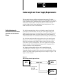
Cable Length and Power Supply Requirements . . . . . . . . .
C1
Cabling Requirements Between the Communications Controller
and the Terminal Blocks . . . . . . . . . . . . . . . . . . . . . . . . . . . .
Maximum Power Cable Lengths . . . . . . . . . . . . . . . . . . . . . . .
Using a Separate Power Supply for a Terminal Block . . . . . . . . . . .
Connecting Power to the Terminal Blocks . . . . . . . . . . . . . . . . .
Cabling and Power Supply Requirements for Loop Power . . . . . . .
C1
C2
C4
C4
C5
Preface
Preface
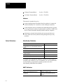
Purpose of the Manual
This manual shows you how to use the Smart Transmitter Interface
products with Allen-Bradley programmable controllers and other
intelligent host computers. It describes how to install and configure the
Smart Transmitter Interface products, as well as how to perform
trouble-shooting procedures.
Organization of the Manual
This manual contains five chapters and three appendices. They address the
following topics:
Chapter
How to Use This Manual
Topics Covered
Chapter 1: Introducing the Smart Transmitter
Interface
overview of the Smart Transmitter Interface;
introduction to the HART protocol, and features
and benefits of using them
Chapter 2: Installing the Smart Transmitter
Interface
installation procedure, power supply
requirements and connection instructions
Chapter 3: Configuring the Communications
Controller
the communication parameters and how to set
them on the Communications Controller
Chapter 4: Communicating with the Smart
Transmitter Interface
Smart Transmitter Interface data routing and
protocol conversion, communication terms,
HART and Smart Transmitter Interface data
packets, PLC5 programming example, and
serial host communication with the Smart
Transmitter Interface
Chapter 5: Troubleshooting
diagnosing communications problems
Appendix A: Product Specifications
technical specifications for 1770HT1, HT8 and
HT16, and HART communications
specifications
Appendix B: DF1 Diagnostic Command Support
diagnostic commands for use on the RS232C
link between a host processor and the
Communications Controller
Appendix C: Cable Length and Power Supply
Requirements
cable length requirements between the
Communications Controller and the Terminal
Blocks, and power supply requirements
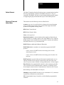
This manual explains the features, functions and specifications of three
products designed to provide communication between Allen-Bradley
products and HARTr field devices. These products are:
Communications Controller
Cat. No. 1770-HT1
P-1
Preface
8 Channel Terminal Block
Cat. No. 1770-HT8
16 Channel Terminal Block
Cat. No. 1770-HT16
Audience
This manual is intended for use by:
persons installing Smart Transmitter Interface products, in connection
with Allen-Bradley PLC controllers or other intelligent controllers
system integrators who are designing and establishing network systems
involving plant floor machinery, programmable controllers, HART field
devices, Smart Transmitter Interface products and host computers
maintenance personnel who maintain such systems and who must
locate, define and correct problems arising during their day-to-day
operation
Related Publications
AllenBradley Publications
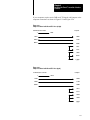
Publication
Reference Number and Date
AllenBradley Data Highway/Data Highway Plust/DH485
Communication Protocol and Command Set Reference
Manual
17706.5.16, November 1991
Analog Input Module User Manual cat. no. 1771IFE
17716.5.90, September 1991
ControlView Core User Manual
61906.5.1, November 1992
PLC5 Family Programmable Controllers Hardware
Installation Manual
17856.6.1
PLC5 Programming Software
62006.4.7
6008SI IBM PC Scanner User's Manual
60086.5.3
A complete list of publications relating to ControlView and its options is
available in the ControlView Core User Manual. For a list of publications
on Allen-Bradley programmable controller products refer to the
Allen-Bradley publication index (SD499).
HART Publications
P-2
Publication
Reference Number and Date
HART - Smart Communications Protocol
Specification
Revision 5.1, January 4, 1991
Rosemount, Inc. Document No. D9000047,
Revision A
Preface
Related Products
The Smart Transmitter Interface Products create a communication interface
between programmable controllers and HART field devices. They are
compatible with HART field devices and with hand-held terminals capable
of supporting the physical and data link layers of the HART protocol.
Glossary of Terms and
Abbreviations
This manual uses the following terms as defined below.
Actuator: any one of several field devices that provide control functions
using a 4-20mA input control signal. Actuators that support the HART
protocol are designated as being “smart”.
BTR: Block Transfer Read
BTW: Block Transfer Write
Clear: (a bit) equal to 0
Hand-held terminal: a smart terminal product capable of functioning as
either a primary or secondary master to one single HART device, using the
HART protocol; this terminal allows the operator to monitor and configure
the HART field device (e.g. Rosemount 268)
HART: Highway Addressable Remote Transducer
HART field device: a transducer or actuator that supports the HART
protocol
- 4-wire: refers to a HART field device drawing power from an
external power source
- 2-wire: refers to a HART field device drawing power from the 4-20
mA loop
HART protocol: a protocol that provides digital communication over an
industry-standard 4-20 mA process control loop at the same time as the
value of a process control variable is being transmitted as a 4-20 mA signal
Host Processor: the programmable controller or host computer (generally
a PC) connected to the Communications Controller over the RIO, or the
host computer connected to the Communications Controller’s RS-232 port
mA: milliamp; one-thousandth of an Ampere
Multidrop: multiple HART field devices (to a maximum of 15), connected
in parallel, per channel on a terminal block
PLC: Programmable Logic Controller; an Allen-Bradley programmable
controller
P-3
Preface
Point-to-point: one HART field device per channel on a terminal block
RIO: Remote Input Output link that supports remote, time-critical, I/O
and control communications between a master PLC controller and its
remote I/O and adapter mode slave processors
Transducer/Transmitter: any one of several field devices that can
measure pressure, temperature, level, flow, density or other process control
variables, and then transmit the value of that variable as a 4-20 mA signal.
Transducers that support the HART protocol are designated as being
“smart”.
P-4
Chapter
1
Introducing the Smart Transmitter Interface
This chapter provides an overview of the Smart Transmitter Interface
products, a brief introduction to the HART protocol and a description of
the different system architectures which can be implemented. It also
describes the features and benefits of using the Smart Transmitter Interface
and lists some of the products that are compatible with the 1770-HT1,
1770-HT8 and 1770-HT16.
Product Overview
The Smart Transmitter Interface products provide a communication
interface between Allen-Bradley PLC controllers or host computers and
HART field devices (transmitters, transducers and actuators). These
products give host processors access to the digital information encoded
with the 4-20 mA analog process control signal. The digital information
can be passed to and from the host processor using either a remote I/O
(RIO) or an RS-232C port.
A Smart Transmitter Interface consists of one Communications Controller
(1770-HT1), and one or more Terminal Blocks (1770-HT8 or 1770-HT16).
These products can be mounted on a DIN rail in a control cabinet and the
field wiring brought directly to the Terminal Blocks.
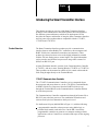
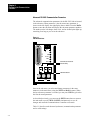
1770HT1 Communications Controller
The 1770-HT1 Communications Controller receives commands from a
host processor and passes them on, via the 1770-HT8/16 Terminal Blocks,
to HART field devices. Responses from the HART field devices go
through the Terminal Blocks to the Communications Controller and then
on to the host processor.
The Communications Controller communicates through its Remote I/O or
RS-232C port to the host processor. The combination of hardware and
software used by the host determines which port is used.
Use the Remote I/O port (labelled RIO in Figure 1.1) with the following:
a programmable controller as host processor using ladder logic to
perform block transfer reads and writes. On the DH+ network the
programmable controller can connect to a computer running software
applications, such as ControlView, to monitor and supervise the ongoing
processes.
1-1
Chapter 1
Introducing the Smart Transmitter
Interface
a programmable controller with Allen-Bradley’s pass-through
functionality connected to a host computer on the DH+ network running
application software to initiate communications
Use the RS-232C port (labelled RS-232 in Figure 1.1) with the following:
a host computer using Allen-Bradley DF1 protocol, connected to the
Communications Controller by an RS-232 cable (if the distance is less
than 50 feet)
a host computer using Allen-Bradley DF1 protocol, connected to the
Communications Controller by telephone lines and modems
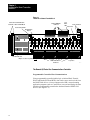
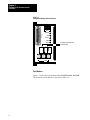
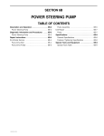
The Communications Controller requires an external 24 VDC power
supply. It provides a multiplexed, 32 channel interface to the Terminal
Blocks. All of the Remote I/O and RS-232C communications parameters
are set on the Communications Controller using push buttons and a seven
segment LED display.
Figure 1.1
1770HT1 Communications Controller
RS-232C
Connector
Connector to Terminal Block(s)
RIO - Connector
Parameter #
Parameter
Setting
Power Connector
Status LEDs
Power Fuse
1
RS-232
1 SH 2
RIO
OPTION
POWER
DATA
SMART TRANSMITTER
COMMUNICATIONS
CONTROLLER
+ 24 VDC
RIO
RS-232
HT8/HT16 INTERCONNECT
HART
FAULT
OPTN
VIEW
DATA
EXIT
SAVE
Push Button Switches
1-2
1
2
3
4
5
6
7
8
NOTES
DATA
OPTN
0.
1.
2.
3.
4.
5.
6.
7.
A.
DATA
17
7-Segment LED
Display
User writeable
areas
90002
Chapter 1
Introducing the Smart Transmitter
Interface
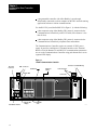
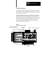
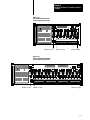
1770HT8/16 Terminal Block
The Terminal Blocks pass both analog and digital signals to and from the
HART field devices. The analog signal is passed on to devices such as the
Allen-Bradley 1771-IFE Analog I/O module. The digital signal is routed to
the Communications Controller.
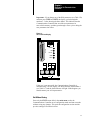
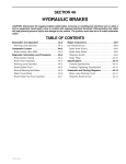
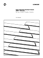
Each Terminal Block provides either 8 (1770-HT8) or 16 (1770-HT16)
channels. Each channel has connection points for HART field devices and
Analog I/O modules, loop fuses and loop power selection jumpers. Any
combination of 8 and 16 channel Terminal Blocks can be used to make up
the 32 channel maximum. The board address jumpers (see Figure 1.2 and
Figure 1.3) indicate to the Communications Controller which set of
channels a particular Terminal Block will use. These are set when the
Terminal Block is installed (see Chapter 2).
Figure 1.2
1770HT8 8 Channel Terminal Block
Connection to Communications
Controller or other Terminal Blocks
Loop
Power
LED
Analog I/O Module
Connector
1
HT1/HT8/HT16 INTERCONNECT
Board Selected LED
Board Address
Jumpers
8 CHANNEL
TERMINAL BLOCK
1
2
3
4
5
6
7
8
Power Fuse Power Connector
+ Loop Power
RTN SH
CATALOG NO. 1770-HT8 VOLTS 24 VDC
E
JP1
DE
JP1
CH 1
CH 2
1 2 SH
1 2 SH
D E
JP1
CH 3
1 2 SH
D E
JP1
CH 4
1 2 SH
D E
JP1
DE
JP1
CH 5
CH 6
1 2 SH
1 2 SH
D E
JP1
CH 7
1 2 SH
D E
JP1
D
CH 8
1 2 SH
17
User writeable area
Jumpers to select Loop Power
HART Transmitters Connectors
Loop Fuses
90018
1-3
Chapter 1
Introducing the Smart Transmitter
Interface
Figure 1.3
1770HT16 16 Channel Terminal Block
Connection to Communications
Controller or other Terminal Blocks
Loop
Power
LED
Analog I/O Module
Connector
1
HT1/HT8/HT16 INTERCONNECT
Board Selected LED
Board Address
Jumpers
8 CHANNEL
TERMINAL BLOCK
1
2
3
4
5
6
7
8
RTN SH
1
2
3
4
5
6
7
8
Power Connector
Power Fuse
+ Loop Power
RTN SH
CATALOG NO. 1770-HT8 VOLTS 24 VDC
E
JP1
DE
JP1
CH 1
CH 2
1 2 SH
1 2 SH
D E
JP1
CH 3
1 2 SH
D E
JP1
CH 4
1 2 SH
D E
JP1
D E
JP1
DE
CH 5
CH 6
1 2 SH
1 2 SH
JP1
CH 7
1 2 SH
D E
JP1
CH 8
1 2 SH
D
E
JP1
JP1
DE
CH 1
1 2 SH
D E
JP1
D E
JP1
D E
JP1
D E
JP1
CH 2
CH 3
CH 4
CH 5
CH 6
1 2 SH
1 2 SH
1 2 SH
1 2 SH
1 2 SH
D E
JP1
CH 7
1 2 SH
D E
JP1
D
CH 8
1 2 SH
17
User writeable area
Jumpers to select Loop Power
HART Transmitters Connectors
Loop Fuses
90017
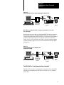
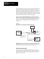
The Remote I/O Port of the Communications Controller
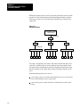
Programmable Controller Host Communications
Using programmable controller ladder logic to initiate Block Transfer
Writes and Reads (BTW and BTR), data can be sent to and received from
the HART field devices. A host computer on the DH+ network running
application programs (such as ControlView) can read and display the data
which the programmable controller has obtained from the HART field
devices. (See Figure 1.4)
1-4
Chapter 1
Introducing the Smart Transmitter
Interface
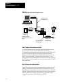
Figure 1.4
Smart Transmitter Interface with Programmable Controller Host
CONTROLVIEW
DH+
RIO
Programmable
Controller with
Ladder Logic
Smart
Transmitter
Interface
HART
Field
Devices
90032
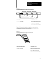
DH+ Host Communications (Using Programmable Controller
Pass-through)
Data can also be sent to and received from HART field devices using the
pass-through feature of the programmable controller to initiate Block
Transfer Reads and Writes (BTR and BTW). No dedicated programmable
controller ladder logic programs are required when the pass-through
feature is used. A host computer on the DH+ network, running programs
with pass-through support, can be used to communicate with the HART
field devices.
Figure 1.5
Smart Transmitter Interface with DH+ Host
(Using Passthrough)
THIRD
PARTY
SOFTWARE
DH+
RIO
Programmable
Controller with
Passthrough
Feature
Smart
Transmitter
Interface
HART
Field
Devices
90033
The RS232C Port of the Communications Controller
The RS-232C port on the Communications Controller allows the HART
field devices to communicate with either a local host or, via modem, a
remote host.
1-5
Chapter 1
Introducing the Smart Transmitter
Interface
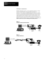
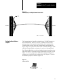
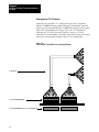
Full Duplex Communications
With DF1 full duplex systems, you can communicate directly to a single
Smart Transmitter Interface. No programmable controllers are
necessary—just a computer running the appropriate software, the HART
field devices, and the Smart Transmitter Interface between them. The host
computer and the Smart Transmitter Interface should be connected with
either an RS-232 cable for distances equal to or less than 50 feet, or two
modems for distances greater than 50 feet. (See Figure 1.6 and Figure 1.7.)
This gives end users with less complex applications, inexpensive access to
HART field devices and to the advantages of the HART protocol.
Figure 1.6
Full Duplex Communication with no Modem
RS-232 CABLE
HOST COMPUTER
Smart
Transmitter
Interface
HART
Field
Devices
90050
Figure 1.7
Full Duplex with Modems
RS-232 CABLE
HOST COMPUTER
Smart
Transmitter
Interface
HART
Field
Devices
90049
1-6
Chapter 1
Introducing the Smart Transmitter
Interface
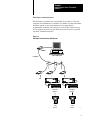
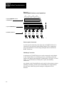
Half Duplex Communications
DF1 half duplex systems can be considerably more extensive. The host
computer can communicate via modems to a number of Smart Transmitter
Interfaces spread out over great distances. Once again, though
programmable controllers can certainly be a part of such a network, they
are not required, and any host with third party software can be used with
the Smart Transmitter Interface.
Figure 1.8
Half Duplex Communications with Modems
MODEM
HOST COMPUTER
Half Duplex
ETC.
Smart
Transmitter
Interface
Smart
Transmitter
Interface
HART
Field
Devices
HART
Field
Devices
90048
1-7
Chapter 1
Introducing the Smart Transmitter
Interface
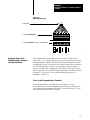
The HART Protocol
The HART field communications protocol carries digital information with
the analog signal over industry-standard 4-20 mA process control loops.
Both the digital and analog signals occur simultaneously on the same loop
wiring without disrupting the process signal.
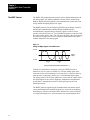
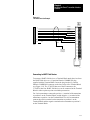
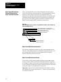
The HART protocol uses the Frequency Shift Keying technique, based on
the Bell 202 communication standard. Digital communication is
accomplished by superimposing a frequency signal over the 4-20 mA
current, as shown in Figure 1.9. Two individual frequencies, 1200 and 2200
Hz, represent the digits 1 and 0. The sine wave formed by the two frequency
levels has an average value of zero, so digital communication takes place
without disruption to the analog signal.
Figure 1.9
Analog and Digital Signals on 420 mA Current
+0.5 mA
Analog
Signal
0
-0.5 mA
1200 Hz
1"
2200 Hz
0"
Average Current Change During Communication = 0
90047
Field devices (transducers, actuators) can use the HART protocol to
transmit or receive a process variable as a 4-20 mA analog signal at the
same time as they are transmitting or receiving device or process data (e.g.
smart pressure, temperature, density, etc.) as a modulated digital signal.
The analog signal, with its faster update rate, can be used for control, while
the digital signal can be used for diagnostic, maintenance and additional
process data. Communication can be in either poll/response or burst
transmission mode.
The HART protocol supports digital communication from both a control
system and a hand-held communications device. It also allows multidrop
networking by which several smart HART field devices can be connected
to a single twisted-pair wire, and can operate over leased telephone lines.
1-8
Chapter 1
Introducing the Smart Transmitter
Interface
The HART Protocol and the Smart Transmitter Interface
Each Communications Controller can communicate with a maximum of 32
channels via the 1770-HT8 and 1770-HT16 Terminal Blocks. As all
channels are multiplexed, communications can only occur over one
channel at a time. Each channel can have one HART field device
connected to it in point-to-point mode, or up to 15 devices in a multidrop
network. The host addresses these channels using channel numbers 0–31
(decimal).
The Communications Controller in the Smart Transmitter Interface
receives HART protocol commands from the host processor (via Remote
I/O or RS-232C connection) and routes these commands (via the Terminal
Blocks) to the HART field devices. The Smart Transmitter Interface
receives responses from the HART field devices and transmits the
responses to the host when it polls for them.
In both multidrop and point-to-point networks each device has a unique
address that is included in every HART message. A device picks up
messages destined to it via this unique address.
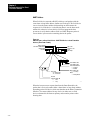
When the Terminal Block receives the composite digital/analog signal
from the HART field devices, it filters out the digital portion of the signal
(see Appendix A for more information on the filtering circuitry), and
passes the analog portion on to an Allen-Bradley Analog I/O module, such
as the 1771-IFE. The Analog I/O module decodes the analog data and
passes it along to the programmable controller.
At the same time, the Terminal Block reads the digital portion of the signal
and multiplexes it to the Communications Controller. The Communications
Controller embeds the digital data into messages conforming to the RIO or
DF1 protocol format, and passes it to the appropriate host processor and its
application program in one of three ways:
to a programmable controller via the remote I/O link
to a computer via the RS-232C port
to a host on the Data Highway Plus network via the pass-through feature
of an Allen-Bradley PLC-5 family programmable controller
Important: You cannot have more than one DH+ host computer using the
pass-through feature or more than one RS-232C host.
1-9
Chapter 1
Introducing the Smart Transmitter
Interface
Poll/Response Mode
The HART protocol supports two modes of digital communications,
poll/response and burst. In poll/response mode the host processor requests
information from (polls) the smart device. Both point-to-point and
multidrop networks can employ this mode.
When the host processor sends a request or control information to the
HART field devices, the Smart Transmitter Interface reads the routing
information in the header portion of the data. It then strips the header off
the message and sends the data down the appropriate channel to the HART
device. Responses from the HART devices are returned to the host
processor when the host polls for them.
If there are no more messages to be forwarded, the Smart Transmitter
Interface stays on the last used channel and watches the traffic. This allows
higher throughput if consecutive messages are sent to the same channel.
Burst Mode
In burst mode the HART field device continuously transmits digital data to
the Communications Controller in burst monitor mode without the need for
request messages from the host. This mode cannot be used with multidrop
networks.
In burst monitor mode, the host processor sends the Smart Transmitter
Interface a list of all the channels whose devices are preset to burst mode.
If the list changes, the host must provide a new list. The Smart Transmitter
Interface continuously monitors the channels on the list in order, returning
to the first as soon as the last has been checked. The data collected from
the burst channels is stored in a Burst Data table. The latest information on
any channel is sent to the host processor upon request.
While in burst monitor mode, the Smart Transmitter Interface still
responds to requests from the host to poll any channel. When the polling is
complete, it resumes monitoring the burst channels.
Features of the Smart
Transmitter Interface
The Smart Transmitter Interface (1770-HT1 and 1770-HT8/16) features
include:
remote I/O port for interface to programmable controllers (RIO
scanners) and DH+ hosts
RS-232C port for interface to serial hosts
7-segment display and push buttons for communications configuration
1-10
Chapter 1
Introducing the Smart Transmitter
Interface
clips for DIN rail mounting
connections to 32 HART field devices in point-to-point configuration
point to point and multidrop wiring support
poll and response or burst digital transmission mode support
connector for providing loop power
interface to Analog I/O modules with 4-20 mA loop support
2 wire and 4 wire transmitters supported
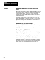
Benefits of Using the Smart
Transmitter Interface
The benefits of using the Smart Transmitter Interface to take advantage of
the HART protocol include the following:
extend programmable controller use in the process area by enabling
Allen-Bradley PLCs to communicate with HART field devices, thus
allowing process monitoring with ControlView or similar applications
software
Because of the added intelligence supplied by the HART field devices,
and the wide range of accurate data available from such devices,
(pressure, temperature, level, flow and density, among others),
automated processes can be monitored accurately over considerable
distances.
reduce downtime and installation time through remote wiring
verification, remote transmitter programming and simple retrofitting
capabilities of HART field devices
Many HART devices are “smart” enough to tell you what is wrong with
them, and how they can be readjusted by remote programming. They
can be, in effect, remote diagnostic tools, as well as remote repair units.
Maintenance becomes simpler and less costly since you no longer need
to send technicians out to the field to perform these tasks manually.
add Smart device capabilities to existing analog systems while
maintaining existing devices
You can add the Smart Transmitter Interface to an existing 4-20 mA
system without having to change the wiring, thus reducing installation
time and expense. Digital capabilities can be gradually implemented,
including digital process variables monitoring, without modifying field
devices.
1-11
Chapter 1
Introducing the Smart Transmitter
Interface
perform configuration and diagnostics of HART field devices using
third party software and the pass-through feature
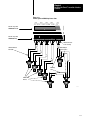
Compatibility
The Smart Transmitter Interface Products create a communication interface
between programmable controllers and HART field devices. (See
Figure 1.10.)
The Smart Transmitter Interface is compatible with HART field devices
and with hand-held terminals capable of supporting the physical and data
link layers of the HART protocol.
Host computers can be any 100% PC compatible computers.
The following products have been tested in connection with the Smart
Transmitter Interface:
PLC5 Family
PLC-5/11
PLC-5/15
PLC-5/20
PLC-5/25
PLC-5/30
PLC-5/40
PLC-5/60
PLC-5/250
You can connect one or more Smart Transmitter Interfaces directly to a
PLC-5 Remote I/O Port (in scanner mode) along with other I/O racks. In
addition, the Smart Transmitter Interface can also be connected to other
remote I/O scanner modules such as the 1771-SN I/O Subscanner module.
For details about which programmable controllers support the pass-through
feature, contact your A-B representative.
HART Field Devices
ABB Kent Taylor K-SC
ABB Kent Taylor K-ST
1-12
Chapter 1
Introducing the Smart Transmitter
Interface
Fischer & Porter 50XM1000B
Micro Motion RFT9739
Moore Products 340B
Princo 50PL4610
Rochester Instrument System SC-6500
Rosemount 1151S
Rosemount 3001C
Rosemount 3001S
Rosemount 3044C
Rosemount 3051C
Rosemount 8712C
Rosemount 8800
Rosemount 9712
Rosemount Analytical 2054pH
Smar LD301
Analog I/O Devices
1771-IE05
1771-IF
1771-IFE
Hand Held Terminal
Rosemount Model 268 Smart Family Interface
1-13
Chapter 1
Introducing the Smart Transmitter
Interface
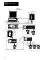
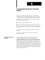
Figure 1.10
A Typical Network
PLC5
1771IFE Modules
DH+
Shielded
Cables
- max.
30 ft.
RIO
Host Computer
1770HT1
1770HT16
1771ASB
RIO Adapter
1771IFE
HART
Field
Devices
1770HT8
Point-to-point
1770HT8
Cable
- max.
10000 ft.
Multidrop
90027
1-14
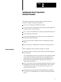
Chapter
2
Installing the Smart Transmitter
Interface Products
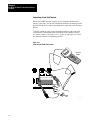
This chapter explains how to install the Smart Transmitter Interface
products. It includes the following information:
an overview of the general installation procedure
how to connect the Communications Controller and Terminal Blocks to
each other so they can communicate
how to connect Terminal Blocks to Analog I/O and HART field devices
system grounding requirements
power supply requirements and connections for the Communications
Controller and Terminal Blocks
how to provide power for HART field devices through the Terminal
Blocks
how to connect the Communications Controller to the host processor
Before You Begin
Before installing the Smart Transmitter Interface you should:
determine where the Communications Controller and Terminal Blocks
are to be placed
The Terminal Blocks should be mounted in the same equipment cabinet
as the Analog I/O modules to which they are to be connected. The
distance between a given Terminal block and its HART field devices
must conform to the HART Protocol specifications and meet the
requirements in Appendix C.
review your setup to ensure that the maximum cable length between the
Communications Controller and the Terminal Blocks is not exceeded.
See the section Connecting the Communications Controller to the
Terminal Blocks for details.
calculate the power requirements of the Communications Controller
(1770-HT1), the Terminal Blocks (1770-HT8/16) and the HART field
devices
2-1
Chapter 2
Installing the Smart Transmitter Interface
Products
Electrostatic Damage
Electrostatic discharge can damage semiconductor devices inside the Smart
Transmitter Interface products. To guard against electrostatic damage,
observe the following precautions:
wear an approved wrist strap grounding device, or touch a grounded
object to rid yourself of electrostatic charge before handling the
products
keep the products in their static-shield bags when not in use
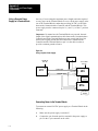
Overview of the Installation
Procedure
2-2
The general procedure for installing the Smart Transmitter Interface
products is as follows:
1.
Mount the Communications Controller and the Terminal Blocks in
their appropriate equipment cabinet (or cabinets).
2.
Connect the Communications Controller to the Terminal Blocks and
set the board address jumpers on the Terminal Blocks.
3.
Connect the Terminal Blocks to I/O modules (1771 I/O devices) and
HART field devices.
4.
Establish the necessary ground connections.
5.
Connect the Communications Controller and Terminal Blocks to a
power supply.
6.
Configure the communications parameters on the Communications
Controller as detailed in Chapter 3.
7.
Connect the Communications Controller to the host through the RIO
or RS-232C port.
Chapter 2
Installing the Smart Transmitter Interface
Products
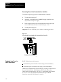
Mounting Smart Transmitter
Interface Products in a Cabinet
Mount the Terminal Blocks in the same equipment cabinet as the Analog
I/O modules to which they will be connected. This ensures the integrity of
the 4-20 mA analog signal being received by the Analog I/O module.
Each unit of the Smart Transmitter Interface is equipped with two plastic
feet designed to attach to an EN 50 022 or EN 50 035 DIN rail. Using
these feet, clip the unit(s) to the DIN rail in the desired position
(Figure 2.1). The units can be mounted in any orientation—horizontally,
vertically, diagonally, etc.
Figure 2.1
Mounting on a DIN Rail
Foot
DIN Rail
90037
To release the feet from the rail, press on the plastic as shown in Figure 2.2
so that the clip is pulled back far enough to release the unit.
Figure 2.2
Releasing From a DIN Rail
Foot
DIN Rail
Press Here
90038
2-3
Chapter 2
Installing the Smart Transmitter Interface
Products
Connecting the
Communications Controller to
the Terminal Blocks
The Communications Controller can support a maximum of 32 HART
channels via the Terminal Blocks. Use any of the following combinations:
one or two 16 Channel Terminal Blocks (1770-HT16)
one, two, three or four 8 Channel Terminal Blocks (1770-HT8)
one 16 Channel Terminal Block and one or two 8 Channel Terminal
Blocks
Digital Communications Cables
The connecting cables should be shielded multi-conductor cables with 8
twisted 20-24 AWG wire pairs. These are not supplied with the Smart
Transmitter Interface. Belden #9508 (24 gauge) or # 85168 cable (20
gauge) or equivalent is recommended. Line 1 is shield, line 2 power and
lines 3 to 17 are control.
The connections between the Communications Controller and the Terminal
Blocks can be either a linear or star topography. You can use any
combination of linear/star connections as long as you adhere to the cabling
length requirements.
If your particular setup requires cable lengths greater than the ones
indicated in Figure 2.3 to Figure 2.5 or is substantially different, refer to
Appendix C.
2-4
Chapter 2
Installing the Smart Transmitter Interface
Products
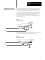
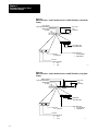
Linear Connection
For linear connection the cables go from the 17 pin connector on the
Communications Controller to the connector on the first Terminal Block.
Another cable of the same kind leads from the connector on the first
Terminal Block to the connector on the second Terminal Block, from there
to the connector on the third Terminal Block, and so on.
Figure 2.3
Example 1: Linear Connection
+ -
+ -
a
1770HT16
b
1770HT1
+ -
1770HT8
c
+ -
1770HT8
90031
Example 1 assumes that the modules (HT1, HT16 and two HT8’s) are
installed in separate cabinets. The maximum cable lengths allowed for the
setup shown in this example are given in the table below.
Cable Size
Belden # 85168
Cable a
Cable b
Cable c
250 ft
250 ft
250 ft
If you are using a linear arrangement, the connector at the
Communications Controller will have one set of 17 wires leading out of it.
The connector at each Terminal Block (except the last one) will have two
sets of wires in the same holes: the one coming from the previous
connection, (either the Communications Controller or the previous
Terminal Block), and the one leading to the next Terminal Block.
2-5
Chapter 2
Installing the Smart Transmitter Interface
Products
Star Connection
For star connection the cables to each Terminal Block lead to the connector
on the Communications Controller directly. If you are using a star
arrangement, the connector at the Communications Controller will have as
many sets of wires leading into it as there are Terminal Blocks. The
connector at each Terminal Block will have only one set of wires, leading
directly back to the Communications Controller.
Figure 2.4
Example 2: Star Connection
+ -
1770HT8
+ -
a
b
+ -
1770HT8
c
+ -
d
1770HT8
+ -
1770HT8
90030
Example 2 assumes that the modules (HT1, and four HT8’s) are installed
in separate cabinets. The table below gives one example of possible cable
lengths.
Cable Size
Belden #85168
2-6
Cable a
Cable b
Cable c
Cable d
250 ft
250 ft
250 ft
250 ft
Chapter 2
Installing the Smart Transmitter Interface
Products
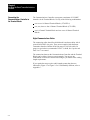
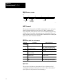
Star/Linear Connection
Example 3 shows a setup where a combination of star and linear
connections are used. In this example, two HT8’s are joined in a linear
connection by cable a (a1 and a2) and the other two HT8’s are joined to the
HT1 in a star connection by cables b and c.
Figure 2.5
Example 3: Star/linear Connection
+ -
+ -
a1
a2
1770HT8
1770HT1
+ -
b
c
1770HT8
+ -
1770HT8
+ -
1770HT8
Cable Size
Belden #85168
90064
Cable a1
Cable a2
Cable b
Cable c
250 ft
200 ft
200 ft
100 ft
2-7
Chapter 2
Installing the Smart Transmitter Interface
Products
Connector and Pinout
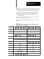
Attach the 17 position Phoenix COMBICON plugs (supplied) to each end
of the cable (see Figure 2.6) then plug them into the units. Use the bare
wire for chassis ground (to be connected at one end only, preferably to the
Communications Controller end). Use only one twisted pair for each "
pair of signals. The colors in the table below are intended as examples
only. You can use any pair you like for any pair of signals. The pinout for
the connector is in the table below.
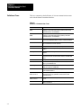
2-8
Signal
Pin
Examples of Colors
Chassis Ground
1 (Shield)
Bare Silver
+24 VDC
2 (Power)
Signal Ground
3 (Control)
Red and White twisted pair;
Red is VDC
VDC, White is Ground
(see Appendix C)
+ Transmit Enable
4 (Control)
- Transmit Enable
5 (Control)
+ Channel Select 1
6 (Control)
- Channel Select 1
7 (Control)
+ Channel Select 2
8 (Control)
- Channel Select 2
9 (Control)
+ Channel Select 3
10 (Control)
- Channel Select 3
11 (Control)
+ Channel Select 4
12 (Control)
- Channel Select 4
13 (Control)
+ Channel Select 5
14 (Control)
- Channel Select 5
15 (Control)
+ HART Tx/Rx
16 (Control)
- HART Tx/Rx
17 (Control)
Red and Black twisted pair;
Red is +,
+ Black is Blue and Black twisted pair
Blue is +,
+ Black is White and Black twisted pair;
White is +,
+ Black is Orange and Black twisted pair;
+ Black is Orange is +,
Brown and Black twisted pair;
Brown is +,
+ Black is Green and Black twisted pair;
Green is +,
+ Black is Yellow and Black twisted pair;
Yellow is +,
+ Black is -
Chapter 2
Installing the Smart Transmitter Interface
Products
Figure 2.6
Attaching Plugs to the Digital Communications Cable
1
1
shield
N/C*
1770HT1
1770HT8
*N/C = no connection
17
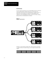
Setting the Board Address
Jumpers
17
90074
The Communications Controller can handle up to 32 HART channels via
the Terminal Blocks. However, since the 32 channels can be divided
among as many as four separate terminal blocks, the Communications
Controller needs to know where one Terminal Block ends and the next
begins. That is, it needs to know which of the 32 channels belong to which
individual Terminal Block, and whether it is an 8 or a 16 channel block.
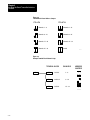
Each Terminal Block has a set of board address jumpers located just to the
right of the black cover near the top edge of the board (see Figure 1.2 and
Figure 1.3). To set a jumper block, lift the black jumper off the pins it is
currently on, re-position it, then push into place. (See Figure 2.7.) Set the
board address jumpers as shown in Figure 2.8.
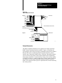
Figure 2.7
Jumper and Pins
90057
2-9
Chapter 2
Installing the Smart Transmitter Interface
Products
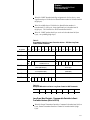
Figure 2.8
Terminal Block Board Address Jumpers
1770-HT8
1770-HT16
Channels 1 - 8
Channels 1 - 16
Channels 9 - 16
Channels 9 - 24
Channels 17 - 24
Channels 17 - 32
Channels 25 - 32
Invalid
90019
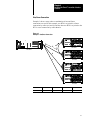
Figure 2.9
Example Terminal Block Channel Setup
TERMINAL BLOCK
HT1
CHANNELS
HT8
1st block
1-8
HT16
2nd block
9 - 24
HT8
3rd block
25 - 32
ADDRESS
JUMPERS
90051
2-10
Chapter 2
Installing the Smart Transmitter Interface
Products
Marking the Terminal Block Labels
On the label on top of each Terminal Block is a place in the lower left hand
corner to record how you have configured the board address jumpers. The
jumper address configuration options for the unit are listed (3 options for
the 16 channel block and 4 for the eight channel block). Mark the box to
indicate which configuration you have used for this Terminal Block. (See
Figure 1.2 and 1.3.) Use a pencil so you can erase the marking if you
change the configuration.
Connecting the Terminal
Blocks to I/O and HART Field
Devices
As shown in Figure 1.10, a Terminal Block can be connected to Analog
I/O devices such as the 1771 IFE module, and to HART field devices. In
addition, a hand held terminal can be connected to the Terminal Block for
communication with HART field devices.
2-11
Chapter 2
Installing the Smart Transmitter Interface
Products
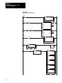
Connecting to 1771 I/O Devices
Attach the wires from the 1771 Analog I/O devices to the 10 position
Phoenix COMBICON plugs supplied with the Terminal Block. Insert the
plug(s) into the 10 position Phoenix COMBICON connectors on the upper
edge of the Terminal Block (see Figure 2.10). The 1771-HT8 has one
connector; the 1771-HT16 has two. Figure 2.11 shows a 1771-IFE
connected to a Terminal Block. The cable between them must be no longer
than 30 feet. Single ended Analog I/O devices are recommended.
Figure 2.10
Connecting the Terminal Block to an Analog I/O Module
To Analog I/O
10 position COMBICON plug
10 position COMBICON connector on Terminal Block
1 2 3 4
5 6 7 8 RTN SH
1 2 3 4 5 6
7 8
RTN SH
90023
2-12
Chapter 2
Installing the Smart Transmitter Interface
Products
Figure 2.11
1771IFE Connection Example
Channel 1
1
Channel 2
2
3
Channel 3
Channel 4
4
Module Common
Channel 5
5
6
Channel 6
7
Channel 7
8
Channel 8
RTN
SH
Module Common
N/C
Shield
1
2
3
4
5
6
7
8
9
10
11
12
HT8/16
13
14
15
Ground Shield
at I/O chassis
mounting bolt
16
17
18
19
20
21
1771-WG
Field Wiring Arm
90052
Connecting to HART Field Devices
To connect a HART field device to a Terminal Block attach the wires from
the HART field device to a 12 position Phoenix COMBICON plug
supplied with the Terminal Block. Insert the plug into the 12 position
Phoenix COMBICON connector on the lower edge of the Terminal Block
(see Figure 2.12). The 1770-HT8 has two of these connectors; the
1770-HT16 has four. HART field devices can be connected to the Terminal
Block in either a point-to-point or multidrop connection.
For 2-wire transmitters connect the positive (+) terminal of the transmitter
to position 2 on the Terminal Block, and the negative (–) terminal of the
transmitter to position 1 on the Terminal Block. For 4-wire transmitters
connect the positive terminal on the transmitter to position 1 on the
Terminal Block and the negative terminal on the transmitter to position 2
on the Terminal Block.
2-13
Chapter 2
Installing the Smart Transmitter Interface
Products
Figure 2.12
Connecting HART Field Devices to the Terminal Block
CH 1
CH 2
1 2 SH
1 2 SH
CH 3
CH 4
CH 5
C
1 2 SH 1 2 SH
12 position COMBICON connector
on Terminal Block
+ -
12 position COMBICON plug
From HART Field Devices
90021
Point-to-point Connection
A point-to-point connection exists when only one HART field device is
connected to any particular Terminal Block channel. This arrangement
allows the transmission of both analog and digital data to and from the
HART field device.
Multidrop Connection
A maximum of 15 HART field devices can be connected to each channel
on the Terminal Block in a multidrop network. A multidrop connection
supplies only digital data through the Terminal Block. See Figure 1.10 and
Figure 2.13 for illustrations of both point-to-point and multidrop
connections.
Any channel on the Terminal Block can be used for either point-to-point or
multidrop networking, and the same Terminal Block can support both at
the same time without any special settings or configuration of the
hardware.
2-14
Chapter 2
Installing the Smart Transmitter Interface
Products
Figure 2.13
Pointtopoint and Multidrop Connections
CH 1
1 2 SH
CH 2
CH 3
CH 4
1 2 SH 1 2 SH 1 2 SH
CH 5
1 2
Phoenix 12 position
COMBICON Header
Phoenix 12 position
COMBICON Plug
Shield Connected
at one end only
Shield bridged
between cables
Shielded Twisted
Pair Cable
Multidrop
Link
HART Field
Devices
90056
2-15
Chapter 2
Installing the Smart Transmitter Interface
Products
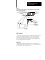
Connecting a Hand Held Terminal
Because the HART protocol supports up to two digital communication
masters at one time, you can use a hand-held terminal to communicate with
the HART field devices without disrupting their connection to the Terminal
Blocks.
To do this, attach the clips of your hand held terminal to either end of the
resistor on the Terminal Block that corresponds to the channel to which
you wish to connect. (See Figure 2.14.) Figure 2.15 and Figure 2.16 show
the channels and their corresponding resistors.
Figure 2.14
Connecting the Hand Held Terminal
Hand Held
Terminal
JP1
E
JP1
D E
CH 1
D
CH 2
`
`
90063
2-16
Chapter 2
Installing the Smart Transmitter Interface
Products
1
HT1/HT8/HT16 INTERCONNECT
Figure 2.15
HT8 Terminal Block Channels
and Corresponding Resistors
8 CHANNEL
TERMINAL BLOCK
1
2
3
4
5
6
7
8
+ Loop Power
RTN SH
CATALOG NO. 1770-HT8 VOLTS 24 VDC
JP1
E
JP1
DE
D E
CH 1
CH 2
1 2 SH
1 2 SH
JP1
JP1
D E
CH 3
1 2 SH
JP1
D E
1 2 SH
JP1
DE
D E
CH 5
CH 6
1 2 SH
1 2 SH
CH 4
JP1
JP1
D E
CH 7
1 2 SH
D
CH 8
1 2 SH
17
Channel 1 resistor
...
Channel 2 resistor
Channel 8 resistor
90068
1
HT1/HT8/HT16 INTERCONNECT
Figure 2.16
HT16 Terminal Block Channels
and Corresponding Resistors
8 CHANNEL
TERMINAL BLOCK
1
2
3
4
5
6
7
8
RTN SH
1
2
3
4
5
6
7
8
+ Loop Power
RTN SH
CATALOG NO. 1770-HT8 VOLTS 24 VDC
E
JP1
DE
JP1
CH 1
CH 2
1 2 SH
1 2 SH
D E
JP1
CH 3
1 2 SH
JP1
D E
CH 4
1 2 SH
D E
JP1
D E
JP1
DE
CH 5
CH 6
1 2 SH
1 2 SH
JP1
CH 7
1 2 SH
D E
JP1
CH 8
1 2 SH
D
E
JP1
DE
CH 1
1 2 SH
JP1
D E
JP1
D E
JP1
D E
JP1
D E
JP1
CH 2
CH 3
CH 4
CH 5
CH 6
1 2 SH
1 2 SH
1 2 SH
1 2 SH
1 2 SH
D E
JP1
CH 7
1 2 SH
D E
JP1
D
CH 8
1 2 SH
17
Channel 1 resistor
Channel 2 resistor
...
Channel 16 resistor
90067
2-17
Chapter 2
Installing the Smart Transmitter Interface
Products
Grounding
Grounding the Communications Controller and Terminal Block
Chassis
Because the Communications Controller and the Terminal Blocks can be as
far as 1000 feet apart it is best to ground each unit locally. To ground the
Communications Controller, connect a wire from the Earth Ground
terminal of its 3 position COMBICON power connector (see Figure 2.18)
to the local ground bus.
Ground each Terminal Block in the same way and insert the plug in the
power connection header for loop power (see Figure 2.19). Each Terminal
Block must be grounded in this way regardless of whether or not it is to
provide 4-20 mA loop power for HART field devices.
Grounding the HART Field Device Cable Shield
Connectors to the HART field devices on the Terminal Blocks are
internally grounded to the power connector. Once the power connector is
properly grounded, these connectors are also properly grounded.
Grounding the Analog I/O Cable Shield
Important: The shield connection in the cable between the Terminal
Blocks and the Analog I/O modules must be grounded at one end only. The
cable must not be more than 30 feet long.
If the Analog I/O module is a 1771-IFE module, ground the shield
connection to the chassis of the 1771-IFE as shown in the documentation
for that module. Do not ground the shield to the Terminal Block connector.
If the Analog I/O module is of another kind, and grounding at that end is
not feasible, you must first connect the cable’s shield wire to the position
on the Terminal Block plug marked SH for Shield (see Figure 2.17).
2-18
Chapter 2
Installing the Smart Transmitter Interface
Products
Figure 2.17
Grounding Analog I/O
To Analog I/O
10 position COMBICON plug
10 position COMBICON connector on Terminal Block
1
2
3
4
5
6
7
8
RTN SH
90045
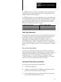
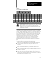
Supplying Power to the
Communications Controller
and Terminal Blocks
The Communications Controller requires an external 24 VDC power
supply with " 1% voltage regulation. The power supply must provide the
Communications Controller with 200 mA of current. It must also provide
an additional 100 mA of current for each Terminal Block that is connected
to the Communications Controller. For example, the setup in Figure 2.3
requires a 24 VDC power supply that can provide at least 500 mA. Please
refer to Appendix C if your cable length requirement exceeds those shown
in Figure 2.3 to Figure 2.5. For recommended power supplies see
Appendix C, Table C.A.
Fuses for the Communications Controller
Overload protection for external power is provided by a 1 Amp
user-replaceable fuse located immediately below the power connector on
the Communications Controller. The fuse is UL 198G and CSA 22.2, No.
59 rated, 5mm x 20mm, 250V fast acting.
2-19
Chapter 2
Installing the Smart Transmitter Interface
Products
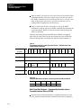
Connecting Power to the Communications Controller
To connect the power supply to the Communications Controller:
1.
Turn the power supply off.
2.
Attach the 3 position Phoenix COMBICON plug (supplied) to the
output cable of the power supply.
3.
Insert the plug into the power connection header on the upper right
corner of the Communications Controller (Figure 2.18).
4.
Turn the power supply on.
Important: Be sure to turn the power off while connecting the cables.
Figure 2.18
Connecting the Power Supply to the Communications Controller
+ 24 VDC
EARTH
GROUND
COMMON
+ 24V DC
Communications Controller
90020
Supplying Loop Power for
HART Field Devices
HART field devices are of two types:
those that draw power from the 4–20 mA loop (2 wire transmitters)
those that require an external power supply (4 wire transmitters)
The HT8/16 Terminal Blocks support both types, and they can be mixed on
the same Terminal Block. Each channel on the Terminal Block has a
jumper block associated with it, JPn. The ‘n’ is the number of the channel
(1 to 8 or 1 to 16). This jumper block indicates the type of HART
transmitter connected to the channel in question.
2-20
Chapter 2
Installing the Smart Transmitter Interface
Products
If a HART field device is a four wire transmitter it must be connected to its
own external power supply and the jumper on the Terminal Block for the
channel in question set to D (disable).
If a HART field device is a two wire transmitter it can be powered through
the Transmitter Block. This requires that the Terminal Block be connected
to an external power supply by the power connection header in the upper
right corner of the block. See Figure 2.19. The jumper on the Terminal
Block for the channel must be set to E (enable).
Set Jumper JP to this position
For this type of HART transmitter
D (Disable loop supply)
External power supply
E (Enable loop supply)
Power drawn from the 420 mA loop
Power Supply Requirements
The external power supply required to power the HART field devices may
be from 24 to 32 VDC. The exact power supply needed depends on the
type of HART field device and the length and gauge of the cable
connecting it to the Terminal Block. For example, a 24 VDC " 0.1%
power supply with a 1 Ampere output would be adequate to supply loop
power to 32 Rosemount 3051C or 3044C field devices over a 20 gauge, or
larger, cable with a length of 1000 feet or less. See Appendix C for further
details.
Fuses for the Terminal Blocks
One fuse on the Terminal Block (either the 1770-HT8 or 1770-HT16) is
for the external power supply providing loop power to HART field devices
through the Terminal Block. It is located immediately to the left of the
power connector. The 1770-HT8 requires a 0.25 Amp fuse and the
1770-HT16 requires a 0.5 Amp fuse. Both fuses should be UL 198G and
CSA 22.2, No. 59 rated, 5mm x 20mm, 250V fast acting.
Connecting the Power Supply for Loop Power
To connect the power supply to the Terminal Block.
1.
Turn the power supply off.
2.
Attach the 3 position Phoenix COMBICON plug supplied with the
product to the output cable of the power supply.
3.
Insert the plug into the power connection header on the upper right
corner of the Terminal Block (Figure 2.19).
2-21
Chapter 2
Installing the Smart Transmitter Interface
Products
4.
Turn the power supply on.
Important: The loop power and ground common wires are only needed if
the HART field devices connected to the Terminal Blocks draw power
from the 4-20 mA current loop instead of from their own individual power
supplies. The earth ground wire is needed, whether or not loop power is
being supplied.
Figure 2.19
Connecting an External Power Supply to a Terminal Block for Loop Power to HART
Field Devices
LOOP POWER
COMMON
EARTH
GROUND
+ Loop Power
Terminal Block
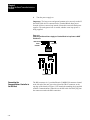
Connecting the
Communications Controller to
the RIO Host
2-22
90028
The RIO connector is a 3 position Phoenix COMBICON connector located
at the left end of the unit, just to the right of the DB-25 connector, at the
top edge of the board (see Figure 2.20). Attach the matching plug (supplied
with the Communications Controller) to the RIO cable. Insert the plug into
the connector to make the RIO connection.
Chapter 2
Installing the Smart Transmitter Interface
Products
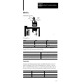
Figure 2.20
RIO Connector
Twinaxial Cable (1770-CD)
Shield
Blue
Clear
1
SH
2
RIO
POWER
RIO
90014
The pinout is:
Signal
Label
Cable
A1
1
Blue wire
A2
SH
Shield
A3
2
Clear wire
Use Twinaxial Cable (1770-CD) for the RIO connections. Maximum
length for the cable depends on the baud rate:
For this baud rate:
Maximum cable length is:
57600
10,000 feet (3,048 m)
115200
5,000 feet (1,524 m)
230400
2,500 feet (762 m)
Termination
Terminate the farthest physical nodes on the RIO link with a 150 or 82
Ohm termination resistor. If the Communications Controller is the last
device on the RIO link, connect a 1/2 watt resistor across pins 1 and 2 of
the plug. The value of the resistor depends on the Remote I/O baud rate:
For this baud rate:
Use this terminating resistor:
AllenBradley Part Number
57600
150W
#74001829
115200
150W
#74001829
230400
82W
#74001823
2-23
Chapter 2
Installing the Smart Transmitter Interface
Products
Activity Indicator
Connecting the
Communications Controller to
the RS232C Host
If the RIO LED is:
The RIO link is:
Off
Inactive
On
Active, normal communication is in progress
Flickering
Communications established, but not active
A single, full or half duplex, RS-232C serial port using the DF1 protocol
provides communications with the host processor. This connector is
located at the left end of the Communications Controller (see Figure 1.1).
The 1770-HT1 is configured as a DTE (Data Terminal Equipment).
RS232C Baud Rates
Baud rates supported are 300, 600, 1200, 2400, 4800, 9600 and 19200.
Cables
Cabling for the RS-232C connector of the Communications Controller will
vary depending on your application.
Use Belden #8723 (or equivalent) cable to construct a cable to connect the
Communications Controller to a computer.
Important: The length must not exceed 50 feet, and the cable shield must
be connected to chassis ground (using Pin 1) at the Communications
Controller end only. If the length required exceeds 50 feet, a modem or line
driver must be used. In addition, if multiple Communications Controllers
are connected to the host processor modems must be used to isolate the
signals.
Activity Indicator
The green LED RS-232 indicator, located to the upper left of the black
cover on the 1770-HT1 (see Figure 1.1), flickers when the
Communications Controller is receiving data over the RS-232C interface.
Connector and Pinout
The RS-232C interface connector at the Communications Controller end is
a DB-25 male connector with the following EIA (Electronics Industries
Association) pinout.
2-24
Chapter 2
Installing the Smart Transmitter Interface
Products
Table 2.A
RS232C Connector Pinouts
ÁÁÁÁÁ
Á
ÁÁÁÁ
ÁÁÁÁÁ
ÁÁÁÁÁ
ÁÁÁÁÁ
ÁÁÁÁÁ
ÁÁÁÁÁ
ÁÁÁÁÁ
ÁÁÁÁÁ
ÁÁÁÁÁ
ÁÁÁÁÁ
ÁÁÁÁÁ
ÁÁÁÁÁ
ÁÁÁÁÁ
ÁÁÁÁÁ
ÁÁÁÁÁ
ÁÁÁÁÁ
ÁÁÁÁÁ
ÁÁÁÁÁ
ÁÁÁÁÁ
ÁÁÁÁÁ
ÁÁÁÁÁ
ÁÁÁÁÁ
ÁÁÁÁÁ
ÁÁÁÁÁ
ÁÁÁÁÁ
ÁÁÁÁÁ
ÁÁÁÁÁ
ÁÁÁÁÁ
ÁÁÁÁÁ
ÁÁÁÁÁ
ÁÁÁÁÁ
ÁÁÁÁÁ
ÁÁÁÁÁ
ÁÁÁÁÁ
ÁÁÁÁÁ
ÁÁÁÁÁ
ÁÁÁÁÁ
ÁÁÁÁÁ
ÁÁÁÁÁ
ÁÁÁÁÁ
ÁÁÁÁÁ
ÁÁÁÁÁ
ÁÁÁÁÁ
ÁÁÁÁÁ
ÁÁÁÁÁ
ÁÁÁÁÁ
ÁÁÁÁÁ
ÁÁÁÁÁ
ÁÁÁÁÁ
ÁÁÁÁÁ
ÁÁÁÁÁ
Signal
Abbreviation
Chassis Ground
I/O
N/A
Transmit Data
TXD
O
Receive Data
RXD
I
Request to Send
RTS
O
Clear to Send
CTS
I
Data Set Ready
DSR
I
Signal Ground
GND
N/A
Data Carrier
Detect
DCD
I
Data Terminal
Ready
DTR
O
ÁÁÁÁ
ÁÁÁÁ
ÁÁÁÁÁÁÁÁÁÁÁÁÁÁÁÁÁÁ
ÁÁÁÁ
ÁÁÁÁ
ÁÁÁÁÁÁÁÁÁÁÁÁÁÁÁÁÁÁ
ÁÁÁÁ
ÁÁÁÁ
ÁÁÁÁÁÁÁÁÁÁÁÁÁÁÁÁÁÁ
ÁÁÁÁ
ÁÁÁÁ
ÁÁÁÁÁÁÁÁÁÁÁÁÁÁÁÁÁÁ
ÁÁÁÁ
ÁÁÁÁ
ÁÁÁÁÁÁÁÁÁÁÁÁÁÁÁÁÁÁ
ÁÁÁÁ
ÁÁÁÁ
ÁÁÁÁÁÁÁÁÁÁÁÁÁÁÁÁÁÁ
ÁÁÁÁ
ÁÁÁÁ
ÁÁÁÁÁÁÁÁÁÁÁÁÁÁÁÁÁÁ
ÁÁÁÁ
ÁÁÁÁ
ÁÁÁÁÁÁÁÁÁÁÁÁÁÁÁÁÁÁ
ÁÁÁÁ
ÁÁÁÁ
ÁÁÁÁÁÁÁÁÁÁÁÁÁÁÁÁÁÁ
ÁÁÁÁ
ÁÁÁÁ
ÁÁÁÁÁÁÁÁÁÁÁÁÁÁÁÁÁÁ
ÁÁÁÁ
ÁÁÁÁ
ÁÁÁÁÁÁÁÁÁÁÁÁÁÁÁÁÁÁ
ÁÁÁÁ
ÁÁÁÁ
ÁÁÁÁÁÁÁÁÁÁÁÁÁÁÁÁÁÁ
ÁÁÁÁ
ÁÁÁÁ
ÁÁÁÁÁÁÁÁÁÁÁÁÁÁÁÁÁÁ
ÁÁÁÁ
ÁÁÁÁ
ÁÁÁÁÁÁÁÁÁÁÁÁÁÁÁÁÁÁ
ÁÁÁÁ
ÁÁÁÁ
ÁÁÁÁÁÁÁÁÁÁÁÁÁÁÁÁÁÁ
ÁÁÁÁ
ÁÁÁÁ
ÁÁÁÁÁÁÁÁÁÁÁÁÁÁÁÁÁÁ
ÁÁÁÁ
ÁÁÁÁ
ÁÁÁÁÁÁÁÁÁÁÁÁÁÁÁÁÁÁ
ÁÁÁÁ
ÁÁÁÁ
ÁÁÁÁÁÁÁÁÁÁÁÁÁÁÁÁÁÁ
ÁÁÁÁ
ÁÁÁÁ
ÁÁÁÁÁÁÁÁÁÁÁÁÁÁÁÁÁÁ
ÁÁÁÁ
ÁÁÁÁ
ÁÁÁÁÁÁÁÁÁÁÁÁÁÁÁÁÁÁ
ÁÁÁÁ
ÁÁÁÁ
ÁÁÁÁÁÁÁÁÁÁÁÁÁÁÁÁÁÁ
ÁÁÁÁ
ÁÁÁÁ
ÁÁÁÁÁÁÁÁÁÁÁÁÁÁÁÁÁÁ
ÁÁÁÁ
ÁÁÁÁ
ÁÁÁÁÁÁÁÁÁÁÁÁÁÁÁÁÁÁ
ÁÁÁÁ
ÁÁÁÁ
ÁÁÁÁÁÁÁÁÁÁÁÁÁÁÁÁÁÁ
ÁÁÁÁ
ÁÁÁÁ
ÁÁÁÁÁÁÁÁÁÁÁÁÁÁÁÁÁÁ
ÁÁÁÁ
ÁÁÁÁ
ÁÁÁÁÁÁÁÁÁÁÁÁÁÁÁÁÁÁ
Direction
Pin Number Meaning
-
1
The cable shield must be connected to chassis ground at one end only.
It is recommended that you do this at the Communications Controller end.
Output
2
RS232C serialized data output from the Communications Controller.
Input
3
RS232C serialized data input to the Communications Controller.
Output
4
A request from the Communications Controller to the modem to prepare to
transmit. With full duplex protocol, RTS is always asserted. With half
duplex protocol, it is turned on when the Communications Controller has
permission to transmit, otherwise it is off.
Input
5
A signal from the modem to the Communications Controller that indicates
the carrier is stable and the modem is ready to transmit. The
Communications Controller will not transmit until CTS is on. If CTS is
turned off during transmission, the Communications Controller will stop
transmitting until CTS is restored.
Input
6
A signal from the modem to the Communications Controller that indicates
the phone is off-hook. It is the modem's answer to DTR. The
Communications Controller will not transmit or receive unless DSR is on. If
the modem does not control DSR properly, DSR must be jumpered to a
high signal at the Communications Controller. (It can be jumpered to
DTR.)
-
7
Signal ground - a reference point for the data signals.
Input
8
A signal from the modem to the Communications Controller to indicate
that the carrier from another modem is being sensed on the phone line. It
will not be asserted unless the phone is off-hook. Data will not be
received by the Communications Controller unless DCD is on. With full
duplex protocol, the Communications Controller will not transmit unless
DCD is on. If the modem does not control DCD properly, DCD must be
jumpered to DTR at the module.
Output
20
A signal from the Communications Controller to the modem to connect to
the phone line (i.e., "pick up the phone"). The Communications Controller
will assert DTR all the time except during the phone hang-up sequence.
Modems built to North American standards will not respond to DTR until
the phone rings. The Communications Controller will not work correctly
with modems which always pick up the phone upon receiving DTR,
whether the phone is ringing or not.
The connector you use at the computer end of the cable depends on
whether or not your application makes use of handshake signals, whether
or not you are connecting to a 9 pin serial port for an IBM AT, and whether
or not your computer uses standard IBM pinouts. The following diagrams,
Figure 2.21 through Figure 2.26, are for IBM computers with either 9 or 25
pin connectors. If your computer has a different pinout, construct a cable
using the appropriate signal names for your computer.
If you are not using handshake signals, use the three wire connections
shown in Figure 2.21 or Figure 2.22.
2-25
Chapter 2
Installing the Smart Transmitter Interface
Products
Figure 2.21
Three Wire Connection to IBM Computer (25 pin)
Female 25 pin connector
to Communications Controller
1
Female 25-pin connector
to Computer
Shield
TXD 2
3 RXD
RXD 3
2 TXD
GND 7
7 GND
90005
Figure 2.22
Three Wire Connection to IBM Computer (9 pin)
Female 25 pin connector
to Communications Controller
1
Female 9-pin connector
to Computer
Shield
TXD 2
2 RXD
RXD 3
3 TXD
GND 7
5 GND
90006
2-26
Chapter 2
Installing the Smart Transmitter Interface
Products
If your computer requires active DSR and CTS signals, add jumpers to the
computer connections as shown in Figure 2.23 and Figure 2.24.
Figure 2.23
Jumper Positions for DSR and CTS Lines (25 pin)
Computer
Communications Controller
1
Shield
TXD 2
3 RXD
RXD 3
2 TXD
GND 7
7 GND
4 RTS
5 CTS
6 DSR
8 DCD
20 DTR
90007
Figure 2.24
Jumper Positions for DSR and CTS Lines (9 pin)
Computer
Communications Controller
1
Shield
TXD 2
2 RXD
RXD 3
3 TXD
GND 7
5 GND
7 RTS
8 CTS
6 DSR
1 DCD
4 DTR
90008
2-27
Chapter 2
Installing the Smart Transmitter Interface
Products
If you are using handshake signals with your computer, use the connection
shown in Figure 2.25 or Figure 2.26.
Figure 2.25
Connection to IBM Computer with Handshake Signals (25 pin)
Communications Controller
1
Computer
Shield
TXD 2
3 RXD
RXD 3
2 TXD
RTS 4
5 CTS
CTS 5
4 RTS
GND 7
7 GND
DSR 6
20 DTR
DCD 8
6 DSR
DTR 20
8 DCD
90009
Figure 2.26
Connection to IBM Computer with Handshake Signals (9 pin)
Computer
Communications Controller
1
Shield
TXD 2
2 RXD
RXD 3
3 TXD
RTS 4
8 CTS
CTS 5
7 RTS
GND 7
5 GND
DSR 6
4 DTR
DCD 8
6 DSR
DTR 20
1 DCD
90010
2-28
Chapter 2
Installing the Smart Transmitter Interface
Products
Modem Connections
The Communications Controller can be connected to a modem via a direct
25-pin to 25-pin cable, which you must construct using Belden #8723 (or
equivalent) cable.
Important: The length of the cable must not exceed 50 feet, and the cable
shield must be connected to chassis ground (using Pin 1) at the Communications
Controller end only.
Figure 2.27
Connection between a Communications Controller RS232C Serial Port and a Modem
MODEM
Communications Controller
1
Shield
TXD 2
2 RXD
RXD 3
3 TXD
RTS 4
4 RTS
CTS 5
5 CTS
DSR 6
6 DSR
GND 7
7 GND
DCD 8
8 DCD
DTR 20
20 DTR
90000
The Communications Controller can be connected to any standard
asynchronous dial-up modem.
Important: Some modems are designed to respond to the DTR signal by
answering the phone whether it is ringing or not. Since the
Communications Controller asserts DTR at all times except during the
hang-up sequence, the phone would always appear to be busy. Do not use
the Smart Transmitter Interface with any type of modem that answers the
phone as soon as DTR is asserted.
The types of dial-up network modems that you can use are:
Manual: these are typically acoustically coupled modems. The
connection is established by human operators at both ends, who insert
the handsets into couplers to complete the connection.
2-29
Chapter 2
Installing the Smart Transmitter Interface
Products
DTE Controlled Answer: these unattended modems are directly
connected to the phone lines. The Smart Transmitter Interface serves as
the data terminal equipment to control the modem via the DTR, DSR
and DCD signals. The Smart Transmitter Interface incorporates timeouts
and tests to operate these types of modems properly.
Auto-Answer: these modems have self-contained timeouts and test, and
can answer and hang up the phone automatically.
The Communications Controller has no means of controlling an auto-dial
modem, but it can be used in conjunction with a separate auto-dialer.
If your application requires the use of leased lines, you will probably not
be using a dial-up modem. Some non-dial-up modems are designed to
assert a continuous DSR signal, a situation that would leave the
Communications Controller waiting forever for communication with the
modem.
To avoid this, construct your cable with the jumper indicated in
Figure 2.28.
Figure 2.28
Connection between a Communications Controller and a Modem
(Other than a Dialup Modem)
MODEM
Communications Controller
1
Jumper
Shield
TXD 2
2 RXD
RXD 3
3 TXD
RTS 4
4 RTS
CTS 5
5 CTS
DSR 6
6 DSR
GND 7
7 GND
DCD 8
8 DCD
DTR 20
20 DTR
90030
2-30
Chapter
3
Configuring the Communications Controller
This chapter explains the communication parameters of the
Communications Controller and describes how to set them. System
integrators need this information to configure the Communications
Controller for the host system.
Overview of Configuration
Procedures
The Communications Controller has two modes of operation, run mode
and configuration mode. During normal operation, the Controller functions
in run mode. When the Controller is in configuration mode you can change
the communication parameters using the push buttons and displays located
at its left end. Any changes you make to the parameter settings do not take
effect until they are saved, which returns the Communications Controller
to run mode. While in configuration mode the Communications Controller
continues to communicate over its ports according to its previous settings.
Important: Verify all parameter settings before connecting the
Communications Controller to your network. Incorrect settings may cause
unreliable and unpredictable operation of the network.
Parameter settings are saved in non-volatile memory so that you do not
lose them even if power to the Communications Controller is interrupted.
Whenever the Communications Controller is in run mode, the seven
segment display is off to conserve power.
Important: If the Communications Controller displays symbols other
than those shown in this chapter, it is malfunctioning. Contact your A-B
representative to arrange to return the unit for servicing.
Displays
Figure 3.1 shows the configuration displays on the left end of the
Communications Controller. The left display (one digit) shows the number
of the communication parameter being configured. The two right displays
(two digits) show the current setting for that parameter. Communication
parameters are configured in two menus, a main menu for basic
parameters, and a sub-menu for more advanced parameters for the
RS-232C port.
3-1
Chapter 3
Configuring the Communications
Controller
Figure 3.1
Configuration Display and Push Buttons
1
SH
2
RIO
RS-232
POWER
RIO
RS232
HART
FAULT
VIEW
Communication Parameter
Current Setting
DATA
EXIT
SAVE
90011
Push Buttons
Figure 3.1 shows three push buttons labelled VIEW, DATA, and EXIT.
The operation of these buttons is described in Table 3.A.
3-2
Chapter 3
Configuring the Communications
Controller
Table 3.A
Push Button Operation
ÁÁÁÁÁÁÁ
ÁÁÁÁÁÁÁÁÁÁÁÁÁÁÁÁÁ
ÁÁÁÁÁÁÁ
ÁÁÁÁÁÁÁÁÁÁÁÁÁÁÁÁÁ
ÁÁÁÁÁÁÁ
ÁÁÁÁÁÁÁÁÁÁÁÁÁÁÁÁÁ
ÁÁÁÁÁÁÁ
ÁÁÁÁÁÁÁÁÁÁÁÁÁÁÁÁÁ
ÁÁÁÁÁÁÁ
ÁÁÁÁÁÁÁÁÁÁÁÁÁÁÁÁÁ
ÁÁÁÁÁÁÁ
ÁÁÁÁÁÁÁÁÁÁÁÁÁÁÁÁÁ
ÁÁÁÁÁÁÁ
ÁÁÁÁÁÁÁÁÁÁÁÁÁÁÁÁÁ
ÁÁÁÁÁÁÁ
ÁÁÁÁÁÁÁÁÁÁÁÁÁÁÁÁÁ
ÁÁÁÁÁÁÁ
ÁÁÁÁÁÁÁÁÁÁÁÁÁÁÁÁÁ
ÁÁÁÁÁÁÁ
ÁÁÁÁÁÁÁÁÁÁÁÁÁÁÁÁÁ
ÁÁÁÁÁÁÁ
ÁÁÁÁÁÁÁÁÁÁÁÁÁÁÁÁÁ
ÁÁÁÁÁÁÁ
ÁÁÁÁÁÁÁÁÁÁÁÁÁÁÁÁÁ
ÁÁÁÁÁÁÁ
ÁÁÁÁÁÁÁÁÁÁÁÁÁÁÁÁÁ
ÁÁÁÁÁÁÁ
ÁÁÁÁÁÁÁÁÁÁÁÁÁÁÁÁÁ
ÁÁÁÁÁÁÁ
ÁÁÁÁÁÁÁÁÁÁÁÁÁÁÁÁÁ
ÁÁÁÁÁÁÁ
ÁÁÁÁÁÁÁÁÁÁÁÁÁÁÁÁÁ
ÁÁÁÁÁÁÁ
ÁÁÁÁÁÁÁÁÁÁÁÁÁÁÁÁÁ
Pressing this button or
button combination:
Performs this task:
VIEW
In run mode, takes the Communications Controller into configuration
mode.
This is the only button that has a function in run mode.
In configuration mode, cycles through the possible communication
parameters (displayed on the left digit).
If you hold the button down for more than 1 second, the parameter
number will advance automatically.
Configuration Step by Step
DATA
In configuration mode, cycles through the possible communication
settings for the parameter shown on the left. The data is displayed on
the right two digits. If you hold the button down for more than 1
second, the settings will advance and accelerate automatically.
When the left display shows 9, press DATA to enter the submenu.
EXIT
In configuration mode, from the main menu, returns the Controller to
run mode without saving any changes. The change in mode takes
effect when the button is released.
From the submenu, returns to the main menu.
VIEW + EXIT
In configuration mode, saves all configuration changes, and returns
the Communications Controller to run mode from either menu. The
Communications Controller will begin operating with the new
configuration as soon as it returns to run mode.
VIEW + DATA
In configuration mode, resets all communication parameters to their
factory defaults (see Table 3.B and Table 3.C ). The changes do not
take effect until the configuration is saved, and the Communications
Controller returns to run modei.e. until VIEW and EXIT are pressed
simultaneously.
Before configuring the Communications Controller, you should determine
the parameters settings your network requires. If they differ from the
factory defaults shown in Table 3.B and Table 3.C, use the following
procedure to change them. While you are changing the parameters in
configuration mode, the Communications Controller continues to
communicate over its ports. The changed parameter settings do not take
effect until they are saved and the Communications Controller returns to
run mode.
Enter Configuration Mode
1.
Press the VIEW button to enter configuration mode. The first
parameter number is displayed on the left display, with its current
setting in the right two displays.
3-3
Chapter 3
Configuring the Communications
Controller
Configure Basic Parameters
2.
Each time you press the VIEW button, the parameter number in the
left display advances, and the parameter’s current setting appears in
the right display.
Press the VIEW button as often as necessary or hold it down until the
desired parameter is reached.
3.
Once the desired parameter is displayed, press the DATA button to
cycle through the available settings.
4.
When you have reached the desired data setting, you can press VIEW
to display the next parameter and its current setting or go to step 7 to
save the change and exit configuration mode.
Repeat steps 2 through 4 until the basic parameter settings meet your
requirements.
Configure Advanced RS232C Parameters
5.
To enter the sub-menu press VIEW until parameter 9 appears in the
left display, then press DATA.
When you are in the sub-menu, the decimal to the right of the
parameter number lights up to distinguish this menu from the main
menu.
6.
Use the VIEW and DATA buttons, as described in steps 2 to 4 to
review and modify the advanced parameter settings.
You can press EXIT to return to the main menu from the sub-menu,
if necessary. This does not end the configuration session and you may
go back to the sub-menu as described in step 5.
Save and Exit
7.
To save the new data and exit configuration mode, press the VIEW
and EXIT buttons simultaneously. All parameters in both the main
menu and the sub-menu will be saved in non-volatile memory, and
the Controller will return to run mode. This ends the configuration
session.
If the save is successful, each display will show three dashes (see
Figure 3.2) for a period of two seconds. When the Communications
Controller returns to run mode, the new configuration takes effect
immediately, and the displays turn off.
3-4
Chapter 3
Configuring the Communications
Controller
Important: If you change any of the RIO parameters (see Table 3.B)
and then press VIEW and EXIT, the display cycles through the
numbers 1–3 after showing the three dashes. This indicates that the
Communications Controller has saved the new parameters in
non-volatile memory, and then gone through a reset cycle to bring the
new parameters into effect.
Figure 3.2
Successful Save Display
1
SH
2
RIO
RS-232
POWER
RIO
RS232
HART
FAULT
VIEW
DATA
EXIT
SAVE
90013
If the save is not successful, the Communications Controller is
malfunctioning. The left display will show hardware fault number 6
(see Table 5.C) and the fault indicator will light. If this happens you
should contact your A-B representative.
Exit Without Saving
Press only the EXIT button while in the main menu to take the
Communications Controller out of configuration mode and into run mode
without saving any changes. This ends the configuration session and the
previous settings will remain in effect.
3-5
Chapter 3
Configuring the Communications
Controller
Pressing only the EXIT button while in the sub-menu takes the
Communications Controller back to the main menu. You can move
between the two menus as much as you need to during any given
configuration session.
Important: If the Communications Controller is left inactive (i.e., with no
buttons pressed) in configuration mode for 3 minutes, it returns to run
mode. Any changes made since going into configuration mode will not be
saved. Also, if power to the Communications Controller is interrupted
while in configuration mode, any changes made will not be saved.
Setting Factory Defaults
Pressing the VIEW and DATA buttons simultaneously when in
configuration mode resets all parameters in both menus to their factory
defaults. When this button combination is pressed, the Communications
Controller displays the first parameter and its factory default.
Like any other changes, the factory default parameters are not saved until
the VIEW and EXIT buttons are pressed simultaneously. If only the EXIT
button is pressed, the Communications Controller returns to run mode
without changing the parameters to their factory defaults.
Communication Parameters
For normal operation, you must configure the basic communication
parameters. For special communication needs you can configure the
advanced communication parameters, which provide more flexibility in the
RS-232C operation of the Communications Controller.
Basic Parameters
The basic communication parameters are divided into two groups:
those that control the Remote I/O link
those that control the RS-232C link
The parameter number is shown in the left display with the current setting
in the two right displays.
Table 3.B describes each basic communication parameter and its valid
settings.
3-6
Chapter 3
Configuring the Communications
Controller
Table 3.B
Main Menu: Basic Communication Parameters
Parameter
Number
Parameter
Description
Factory Default
Rack Address
Defines the address of the rack containing the Communications Controller.
Valid choices are Programmable Logic Controller dependent; maximum is 77
(octal).
01
Starting Module Group
Defines the address of the Communications Controller within the rack.
Valid choices are 00, 02, 04, 06
00
Last Module
Is this the last module in the current rack? No (00), Yes (01)
No (00)
RIO Parameters
ÁÁÁÁÁÁ
ÁÁÁÁÁÁ
ÁÁÁÁÁÁÁÁÁÁÁÁÁÁÁÁÁÁÁ
ÁÁÁÁÁÁ
ÁÁÁÁÁÁ
ÁÁÁÁÁÁ
ÁÁÁÁÁÁÁÁÁÁÁÁÁÁÁÁÁÁÁ
ÁÁÁÁÁÁ
ÁÁÁÁÁÁ
ÁÁÁÁÁÁ
ÁÁÁÁÁÁÁÁÁÁÁÁÁÁÁÁÁÁÁ
ÁÁÁÁÁÁ
ÁÁÁÁÁÁ
ÁÁÁÁÁÁ
ÁÁÁÁÁÁÁÁÁÁÁÁÁÁÁÁÁÁÁ
ÁÁÁÁÁÁ
ÁÁÁÁÁÁ
ÁÁÁÁÁÁ
ÁÁÁÁÁÁÁÁÁÁÁÁÁÁÁÁÁÁÁ
ÁÁÁÁÁÁ
ÁÁÁÁÁÁ
ÁÁÁÁÁÁ
ÁÁÁÁÁÁÁÁÁÁÁÁÁÁÁÁÁÁÁ
ÁÁÁÁÁÁ
ÁÁÁÁÁÁÁÁÁÁÁÁÁÁÁÁÁÁÁÁÁÁÁÁÁÁÁÁÁÁÁÁÁÁ
ÁÁÁÁÁÁ
ÁÁÁÁÁÁ
ÁÁÁÁÁÁÁÁÁÁÁÁÁÁÁÁÁÁÁ
ÁÁÁÁÁÁ
ÁÁÁÁÁÁÁÁÁÁÁÁÁÁÁÁÁÁÁÁÁÁÁÁÁÁÁÁÁÁÁÁÁÁ
ÁÁÁÁÁÁ
ÁÁÁÁÁÁ
ÁÁÁÁÁÁÁÁÁÁÁÁÁÁÁÁÁÁÁ
ÁÁÁÁÁÁ
ÁÁÁÁÁÁ
ÁÁÁÁÁÁ
ÁÁÁÁÁÁÁÁÁÁÁÁÁÁÁÁÁÁÁ
ÁÁÁÁÁÁ
ÁÁÁÁÁÁ
ÁÁÁÁÁÁ
ÁÁÁÁÁÁÁÁÁÁÁÁÁÁÁÁÁÁÁ
ÁÁÁÁÁÁ
ÁÁÁÁÁÁ
ÁÁÁÁÁÁ
ÁÁÁÁÁÁÁÁÁÁÁÁÁÁÁÁÁÁÁ
ÁÁÁÁÁÁ
ÁÁÁÁÁÁ
ÁÁÁÁÁÁ
ÁÁÁÁÁÁÁÁÁÁÁÁÁÁÁÁÁÁÁ
ÁÁÁÁÁÁ
ÁÁÁÁÁÁ
ÁÁÁÁÁÁ
ÁÁÁÁÁÁÁÁÁÁÁÁÁÁÁÁÁÁÁ
ÁÁÁÁÁÁ
ÁÁÁÁÁÁ
ÁÁÁÁÁÁ
ÁÁÁÁÁÁÁÁÁÁÁÁÁÁÁÁÁÁÁ
ÁÁÁÁÁÁ
ÁÁÁÁÁÁ
ÁÁÁÁÁÁ
ÁÁÁÁÁÁÁÁÁÁÁÁÁÁÁÁÁÁÁ
ÁÁÁÁÁÁ
ÁÁÁÁÁÁ
ÁÁÁÁÁÁ
ÁÁÁÁÁÁÁÁÁÁÁÁÁÁÁÁÁÁÁ
ÁÁÁÁÁÁ
ÁÁÁÁÁÁ
ÁÁÁÁÁÁ
ÁÁÁÁÁÁÁÁÁÁÁÁÁÁÁÁÁÁÁ
ÁÁÁÁÁÁ
ÁÁÁÁÁÁ
ÁÁÁÁÁÁ
ÁÁÁÁÁÁÁÁÁÁÁÁÁÁÁÁÁÁÁ
ÁÁÁÁÁÁ
ÁÁÁÁÁÁ
ÁÁÁÁÁÁ
ÁÁÁÁÁÁÁÁÁÁÁÁÁÁÁÁÁÁÁ
ÁÁÁÁÁÁ
ÁÁÁÁÁÁ
ÁÁÁÁÁÁ
ÁÁÁÁÁÁÁÁÁÁÁÁÁÁÁÁÁÁÁ
ÁÁÁÁÁÁ
ÁÁÁÁÁÁÁÁÁÁÁÁÁÁÁÁÁÁÁÁÁÁÁÁÁÁÁÁÁÁÁÁÁÁ
ÁÁÁÁÁÁ
ÁÁÁÁÁÁ
ÁÁÁÁÁÁÁÁÁÁÁÁÁÁÁÁÁÁÁ
ÁÁÁÁÁÁ
ÁÁÁÁÁÁ
ÁÁÁÁÁÁ
ÁÁÁÁÁÁÁÁÁÁÁÁÁÁÁÁÁÁÁ
ÁÁÁÁÁÁ
ÁÁÁÁÁÁÁÁÁÁÁÁÁÁÁÁÁÁÁÁÁÁÁÁÁÁÁÁÁÁÁÁÁÁ
ÁÁÁÁÁÁ
ÁÁÁÁÁÁ
ÁÁÁÁÁÁÁÁÁÁÁÁÁÁÁÁÁÁÁ
ÁÁÁÁÁÁ
ÁÁÁÁÁÁ
ÁÁÁÁÁÁ
ÁÁÁÁÁÁÁÁÁÁÁÁÁÁÁÁÁÁÁ
ÁÁÁÁÁÁ
ÁÁÁÁÁÁ
ÁÁÁÁÁÁ
ÁÁÁÁÁÁÁÁÁÁÁÁÁÁÁÁÁÁÁ
ÁÁÁÁÁÁ
ÁÁÁÁÁÁ
ÁÁÁÁÁÁ
ÁÁÁÁÁÁÁÁÁÁÁÁÁÁÁÁÁÁÁ
ÁÁÁÁÁÁ
ÁÁÁÁÁÁ
ÁÁÁÁÁÁ
ÁÁÁÁÁÁÁÁÁÁÁÁÁÁÁÁÁÁÁ
ÁÁÁÁÁÁ
ÁÁÁÁÁÁ
ÁÁÁÁÁÁ
ÁÁÁÁÁÁÁÁÁÁÁÁÁÁÁÁÁÁÁ
ÁÁÁÁÁÁ
To save time in RIO communications, and to make sure all modules in a rack are
read, be sure only the last logical module in each rack is configured as Yes.
Baud Rate
Sets the baud rate (the speed in bits/second at which data is transferred) of the
link between the Communications Controller and Remote I/O scanner.
Possible rates are 57.6 (57), 115.2 (11), 230.4 (23) Kbits/s
57.6 (57)
RS232C Baud Rate
Sets the baud rate of the link between the Communications Controller and the
RS232C port of the host computer. The host computer and the Communications
Controller must be set to the same baud rate. Possible rates are 300 (03), 600
(06), 1200 (12), 2400 (24), 4800 (48), 9600 (96), 19200 (19) Bits/s
9600 (96)
RS232C Parity
Parity of the characters on the RS232C link. The host computer and the
Communications Controller must have the same parity setting.
Parity can be None (00), Even (01), or Odd (02).
None (00)
DF1 Protocol
Sets the DF1 protocol as being either: Fullduplex (00) or Halfduplex (01).
Full Duplex (00)
Error Detection
Two forms of error checking are available on the RS232C link: BCC Block Check
Code (00) or CRC16 Cyclic Redundancy Check (01).
The application program running on the host computer must use the same error
detection as the Communications Controller. Refer to your application's
documentation to determine what error detection it is using, and set the
Communications Controller to the same setting.
BCC (00).
Station Address
The station address of this Communications Controller on the RS232C link.
Valid addresses are 00-77 (octal) inclusive.
00
Submenu Parameters
Lets you into the submenu when the DATA key is pressed, to set the advanced
communication parameters; the data display will show two dashes.
See the section below on Advanced communication parameters for more
information.
N/A
Series and Revision
Displays the series and revision level of the Communications Controller. The first
digit shows the series (A-J), the second the revision (A-J). For example, Series A
Revision B is displayed as AB.
You cannot set this value.
N/A
RS232C Parameters
Other Parameters
3-7
Chapter 3
Configuring the Communications
Controller
Advanced RS232C Communication Parameters
The advanced communication parameters for the RS-232C link are located
in the sub-menu. When parameter 9, the sub-menu entry parameter, is
shown on the left display, the right display shows dashes. Press the DATA
button to enter the sub-menu and display the sub-menu parameter numbers.
The number on the left changes from 9 to 0, and its decimal point lights up,
remaining lit as long as you are in the sub-menu.
Figure 3.3
SubMenu Indicator
1
SH
2
RIO
RS-232
POWER
RIO
RS232
HART
FAULT
Communication Parameter
Current Setting
SubMenu Indicator
VIEW
DATA
EXIT
SAVE
90012
Once in the sub-menu, you select and change parameters in the same
manner as in the main menu, using the VIEW and DATA buttons. When
the last sub-menu parameter is reached, you can press VIEW to go back to
the first sub-menu parameter.
As described previously, you can press the EXIT button alone to return to
the main menu or press VIEW and EXIT simultaneously to save all
changes and return the Communications Controller to run mode.
Table 3.C describes each advanced (sub-menu) communication parameter
and its valid settings.
3-8
Chapter 3
Configuring the Communications
Controller
Table 3.C
SubMenu: Advanced RS232C Communication Parameters
Parameter Number
Parameter
Description
Factory Default
Number of Retries
Number of allowable retries per attempt on the RS232C link:
Valid numbers are 00 (no retries per attempt) to 10 (10 retries per
attempt).
02
DF1 ACK Timeout
The time to wait for an acknowledgement (ACK) from the host
computer. The timeout is from 0.1 to 5 seconds in 0.1 second
increments (1-50). To calculate the timeout, multiply the number in the
display by 0.1 second.
For example, a setting of 14 means 14 x 0.1 = 1.4 seconds.
1 second (10)
Flow Control
Determines whether modem handshake lines are used for flow control:
Disabled (00), Enabled (01).
Disabled (00)
ÁÁÁÁÁÁ
ÁÁÁÁÁÁÁÁ
ÁÁÁÁÁÁÁÁÁÁÁÁÁÁÁÁ
ÁÁÁÁÁÁÁ
ÁÁÁÁÁÁ
ÁÁÁÁÁÁÁÁ
ÁÁÁÁÁÁÁÁÁÁÁÁÁÁÁÁ
ÁÁÁÁÁÁÁ
ÁÁÁÁÁÁ
ÁÁÁÁÁÁÁÁ
ÁÁÁÁÁÁÁÁÁÁÁÁÁÁÁÁ
ÁÁÁÁÁÁÁ
ÁÁÁÁÁÁ
ÁÁÁÁÁÁÁÁ
ÁÁÁÁÁÁÁÁÁÁÁÁÁÁÁÁ
ÁÁÁÁÁÁÁ
ÁÁÁÁÁÁ
ÁÁÁÁÁÁÁÁ
ÁÁÁÁÁÁÁÁÁÁÁÁÁÁÁÁ
ÁÁÁÁÁÁÁ
ÁÁÁÁÁÁ
ÁÁÁÁÁÁÁÁ
ÁÁÁÁÁÁÁÁÁÁÁÁÁÁÁÁ
ÁÁÁÁÁÁÁ
ÁÁÁÁÁÁ
ÁÁÁÁÁÁÁÁ
ÁÁÁÁÁÁÁÁÁÁÁÁÁÁÁÁ
ÁÁÁÁÁÁÁ
ÁÁÁÁÁÁ
ÁÁÁÁÁÁÁÁ
ÁÁÁÁÁÁÁÁÁÁÁÁÁÁÁÁ
ÁÁÁÁÁÁÁ
ÁÁÁÁÁÁ
ÁÁÁÁÁÁÁÁ
ÁÁÁÁÁÁÁÁÁÁÁÁÁÁÁÁ
ÁÁÁÁÁÁÁ
ÁÁÁÁÁÁ
ÁÁÁÁÁÁÁÁ
ÁÁÁÁÁÁÁÁÁÁÁÁÁÁÁÁ
ÁÁÁÁÁÁÁ
ÁÁÁÁÁÁ
ÁÁÁÁÁÁÁÁ
ÁÁÁÁÁÁÁÁÁÁÁÁÁÁÁÁ
ÁÁÁÁÁÁÁ
ÁÁÁÁÁÁ
ÁÁÁÁÁÁÁÁ
ÁÁÁÁÁÁÁÁÁÁÁÁÁÁÁÁ
ÁÁÁÁÁÁÁ
ÁÁÁÁÁÁ
ÁÁÁÁÁÁÁÁ
ÁÁÁÁÁÁÁÁÁÁÁÁÁÁÁÁ
ÁÁÁÁÁÁÁ
ÁÁÁÁÁÁ
ÁÁÁÁÁÁÁÁ
ÁÁÁÁÁÁÁÁÁÁÁÁÁÁÁÁ
ÁÁÁÁÁÁÁ
ÁÁÁÁÁÁ
ÁÁÁÁÁÁÁÁ
ÁÁÁÁÁÁÁÁÁÁÁÁÁÁÁÁ
ÁÁÁÁÁÁÁ
ÁÁÁÁÁÁ
ÁÁÁÁÁÁÁÁ
ÁÁÁÁÁÁÁÁÁÁÁÁÁÁÁÁ
ÁÁÁÁÁÁÁ
ÁÁÁÁÁÁ
ÁÁÁÁÁÁÁÁ
ÁÁÁÁÁÁÁÁÁÁÁÁÁÁÁÁ
ÁÁÁÁÁÁÁ
ÁÁÁÁÁÁ
ÁÁÁÁÁÁÁÁ
ÁÁÁÁÁÁÁÁÁÁÁÁÁÁÁÁ
ÁÁÁÁÁÁÁ
ÁÁÁÁÁÁ
ÁÁÁÁÁÁÁÁ
ÁÁÁÁÁÁÁÁÁÁÁÁÁÁÁÁ
ÁÁÁÁÁÁÁ
ÁÁÁÁÁÁ
ÁÁÁÁÁÁÁÁ
ÁÁÁÁÁÁÁÁÁÁÁÁÁÁÁÁ
ÁÁÁÁÁÁÁ
ÁÁÁÁÁÁ
ÁÁÁÁÁÁÁÁ
ÁÁÁÁÁÁÁÁÁÁÁÁÁÁÁÁ
ÁÁÁÁÁÁÁ
ÁÁÁÁÁÁ
ÁÁÁÁÁÁÁÁ
ÁÁÁÁÁÁÁÁÁÁÁÁÁÁÁÁ
ÁÁÁÁÁÁÁ
ÁÁÁÁÁÁ
ÁÁÁÁÁÁÁÁ
ÁÁÁÁÁÁÁÁÁÁÁÁÁÁÁÁ
ÁÁÁÁÁÁÁ
ÁÁÁÁÁÁ
ÁÁÁÁÁÁÁÁ
ÁÁÁÁÁÁÁÁÁÁÁÁÁÁÁÁ
ÁÁÁÁÁÁÁ
ÁÁÁÁÁÁ
ÁÁÁÁÁÁÁÁ
ÁÁÁÁÁÁÁÁÁÁÁÁÁÁÁÁ
ÁÁÁÁÁÁÁ
ÁÁÁÁÁÁ
ÁÁÁÁÁÁÁÁ
ÁÁÁÁÁÁÁÁÁÁÁÁÁÁÁÁ
ÁÁÁÁÁÁÁ
Flow control is normally enabled when communicating with a modem.
CTS to TX Delay
The delay between the Clear to Send (CTS) signal and the start of
transmission (half duplex only). The delay is from 0 seconds to 0.99
seconds in 10 ms (0.01 second) increments (00-99). To calculate the
delay, multiply the number in the display by 0.01 seconds.
No delay (00)
For example, a setting of 48 means 48 x 0.01 = 0.48 seconds.
This parameter only takes effect when the Controller is in half duplex
mode and handshaking is enabled. It is only required when
communicating with radio modems that require a delay after exerting
the CTS signal. Refer to your modem manual for this information.
End of Message to RTS
Off
The delay between the end of a message and the Communications
Controller setting Request to Send (RTS) inactive. The delay is from 0
seconds to 0.99 seconds, in 10 ms (0.01 second) increments (00-99).
To calculate the delay, multiply the number in the display by 0.01
seconds.
For example, a setting of 50 means 50 x 0.01 seconds = 0.50
seconds.
This parameter is only required when communicating with modems
that require a delay between sending the last character and raising the
RTS signal. Refer to your modem manual for this information.
No delay (00).
This parameter only takes effect when the Communications Controller
is in HalfDuplex DF1 mode, and handshaking is enabled.
Duplicate Message
Detection
Determines whether duplicate message detection is enabled: Disabled
(00), Enabled (01).
Enabled (01)
If enabled, the Communications Controller will acknowledge and
discard duplicate messages.
3-9
Chapter 3
Configuring the Communications
Controller
Verifying the Communication
Parameters
Before connecting the Communications Controller to your network, cycle
through the parameter settings and verify that they are correct for your
network. If you have made no changes to the default settings they should
appear in the displays.
When you connect the Communications Controller to your network and
turn it on, the displays cycle through the numbers 1–3 and then turn off. If
your parameters are correctly configured, and the Controller is connected
to the RIO link, the RIO LED on the Controller lights up. If the RIO LED
flashes instead of glowing steadily, make sure that only the last module in
the rack has its Last Module parameter set to Yes.
Once you initiate active communication on the DF1 link, the RS-232
Activity LED flashes to reflect communication activity. If this fails to
happen, check the RS-232C parameters (Table 3.B, Parameters 4–8, and
Table 3.C) or the RS-232C cable.
If the displays show symbols other than those shown in this chapter, the
Controller is malfunctioning. You should contact your A-B representative
to arrange to return the unit for servicing.
For more information on troubleshooting see Chapter 5.
Marking the Communications Controller Label
When you have configured and verified the communication parameters,
record the configuration on the label on top of the unit. In the lower left
hand corner of the label is a section entitled Notes. This lists the parameter
number (OPTN) for the main menu and sub-menu options and provides
space for the current settings (DATA). Mark these in with a pencil so they
can be changed if the configuration changes. (See Figure 1.1.)
3-10
Chapter
4
Communicating with the Smart Transmitter
Interface
This chapter provides programming information for communication
between host processors (programmable controllers and host computers)
and HART field devices via the Smart Transmitter Interface. It includes:
explanations of the data routing and protocol conversion functions of
the Smart Transmitter Interface
definitions of relevant communication terms
descriptions of HART and Smart Transmitter Interface data packets
a PLC-5 programming example that illustrates the use of these packets
for communicating between programmable controllers and HART field
devices
an explanation of serial communications with the Smart Transmitter
Interface
a brief note on using Data Highway Plus hosts with the Smart
Transmitter Interface
Data Routing and Protocol
Conversion
The Smart Transmitter Interface routes data packets between host
processors and HART field devices as illustrated in Figure 4.1.
Programmable controllers send and receive Smart Transmitter Interface
packets on the RIO link. Host computers send and receive DF1 packets on
the RS-232C link. The Smart Transmitter Interface converts the packets
from the host processor into packets conforming to the HART protocol (by
extracting the HART data and adding preambles) and relays them to the
specified HART field device. When it receives a packet from a HART field
device, the Smart Transmitter Interface converts it into the packet format
appropriate to the host processor and sends it on when required. The Smart
Transmitter Interface and HART field devices send and receive HART
packets over the 4-20 mA loops.
4-1
Chapter 4
Communicating with the Smart
Transmitter Interface
Communicating with the Smart Transmitter
Interface
Figure 4.1
System Data Flows with a Smart Transmitter Interface
DF1 Commands
All packets on this
link are DF1 packets
DF1 Responses
Host Computer
BTW Data
RS232C
RIO
BTR Data
Programmable
Controller
HART Poll
All packets on this link
are Smart Transmitter Interface
packets
All packets on this link
are HART packets
HART Response
or
HART Burst Data
HART
Field
Devices
420 mA
Loop
90065
Data Routing In Poll and Response Mode
A Smart Transmitter Interface operating in the Poll and Response mode
receives packets as Block Transfer Write (BTW) data from a
programmable controller and forwards those packets as HART polls to the
field device. When the field device responds, the Smart Transmitter
Interface routes that response to the programmable controller as data in a
Block Transfer Read (BTR). The Smart Transmitter Interface receives
similar packets from, and sends them to the host processor on the RS-232C
link in the form of DF1 commands and responses instead of Block Transfer
Writes and Reads.
Data Routing in Burst Monitor Mode
In Burst Monitor mode the Smart Transmitter Interface watches specified
channels for HART burst data from field devices and places this data in a
Burst Data table. Programmable controllers request this data via a BTW to
the Smart Transmitter Interface which returns the data from the Burst Data
Table in a BTR. Host computers request and receive this data via DF1
commands and responses rather than BTWs and BTRs.
4-2
Chapter 4
Communicating
with the Smart
C
Transmitter Interface
Figure 4.2
Layered Nature of Protocols
Layer 3
DF1 Packet
DLE
STX
DST
SRC
CMD
STS
TNS
FNC
LEN
BCC/CRC
ETX
DLE
Smart Transmitter Interface Packet
Layer 2
Smart Transmitter Interface Command
Channel Number
Control
Parameter
Layer 1
HART Packet
Preamble
Delimiter
Address
HART Command
Byte Count
Data
Check Byte
90066
Protocol Conversion
The Smart Transmitter Interface receives data in one of three protocols:
HART, Smart Transmitter Interface and DF1. Figure 4.2 illustrates the
layered nature of these three protocols as transmitted from a host computer.
Here the DF1 packet contains the Smart Transmitter Interface packet,
which in turn, contains the HART packet. The Smart Transmitter Interface
converts all received packets to the required format before transmitting
them to their destination. As mentioned previously, when sending a packet
to a HART field device, it adds preamble bytes. When sending a packet to
the host processor the Smart Transmitter Interface attaches a four byte
header. The contents of these bytes are explained in the sections describing
the various packets.
4-3
Chapter 4
Communicating with the Smart
Transmitter Interface
Definition of Terms
Communicating with the Smart Transmitter
Interface
Table 4.A summarizes the definitions of relevant communications terms
used with the Smart Transmitter Interface.
Table 4.A
Definitions of Communications Terms
Term
4-4
Definition
Block Transfer Read
(BTR)
A programmable controller ladder logic instruction to obtain data
(formatted as Smart Transmitter Interface packets) from the Smart
Transmitter Interface over the RIO link.
Block Transfer Write
(BTW)
A programmable controller ladder logic instruction to send data
(formatted as Smart Transmitter Interface packets) to the Smart
Transmitter Interface over the RIO link.
Burst Data Table
An internal table maintained by the Smart Transmitter Interface which
stores the latest HART Burst Data received on a monitored channel.
DF1 Protocol
An AllenBradley proprietary protocol which defines the format of data
packets transmitted over an RS232C link.
DF1 Packet
A data packet formatted according to the DF1 protocol.
DF1 Command
A DF1 packet transmitted by a host computer to the Smart Transmitter
Interface.
DF1 Response
A DF1 packet transmitted by the Smart Transmitter Interface to a host
computer.
HART Protocol
A communications protocol defining the format of data packets
transmitted between the Smart Transmitter Interface and HART field
devices.
HART Packet
A data packet formatted according to the HART Protocol.
HART Poll
A HART Packet sent by the Smart Transmitter Interface to a field
device to poll or write data to it.
HART Response
A HART Packet sent by the field device to the Smart Transmitter
Interface in response to a HART Poll.
HART Burst Data
An unsolicited HART Packet sent periodically by a field device to the
Smart Transmitter Interface.
Smart Transmitter
Interface Protocol
A communications protocol defining the format of data packets
transmitted between a programmable controller and the Smart
Transmitter Interface.
Smart Transmitter
Interface Packet
Data packets formatted according to the Smart Transmitter Interface
Protocol.
Frame
Frame is another word for packet used extensively in Rosemount
HART documentation.
Chapter 4
Communicating
with the Smart
C
Transmitter Interface
HART Poll Packets
The Smart Transmitter Interface transmits HART Poll packets to field
devices using the format illustrated in Figure 4.3 and Figure 4.4. The host
processor provides data for all fields except the preamble. If you are using
a programmable controller as host processor, you provide data for the
HART device via Block Transfer Writes to the Smart Transmitter Interface.
If you are using a computer as host processor, you provide the data by
using the computer’s software to send DF1 commands to the Smart
Transmitter Interface.
Preamble
The preamble is a number of hexadecimal FF characters that precede all
frames sent to the HART field device. The size depends on the field
devices being used, but it can be from 2 to 32 hexadecimal. The default is
10. The Smart Transmitter Interface inserts the required preamble before
each packet or frame transmission to the HART device. This is done
automatically so you do not have to program the host processor to do this.
HART Delimiter
This is a one-byte field that is used to identify the frame type. Set the
frame type as STX (010) to identify this packet as a HART poll. Also,
indicate whether a short or long frame address follows this byte, by
specifying hexadecimal 02 for a short frame address or hexadecimal 82 for
a long frame address.
HART Address
The Smart Transmitter Interface addresses HART field devices using either
a short or long frame address format (as specified by the HART Delimiter
byte). A short frame address is one byte long and contains a polling
address from 0 to 15. A long frame address is five bytes long and includes
a unique 38 bit identifier encoded within each field device by the
manufacturer.
HART field device addressing is device dependent. Some devices do not
support long frame addressing while others only recognize short frame
addressing for HART Command #0. In this situation, use HART Command
#0 to determine the long frame address, and then use long frame
addressing for all other HART commands. Consult the documentation
provided with your field device for details about the addressing formats it
supports.
4-5
Chapter 4
Communicating with the Smart
Transmitter Interface
Communicating with the Smart Transmitter
Interface
Figure 4.3
HART Poll Packets Smart Transmitter Interface to HART Field Device (Short Frame
Format)
Hart Command
Short Frame HART Address
HART Delimiter
Preamble
Byte Count
Data
Check Byte
0
Slave Address Bits
Logical Address Bits
0 0 0 0 0
Master Address Bit
0 Secondary Master
1 Primary Master
Frame Type
010 STX Frame
Reserved
Long/Short Frame Bit
0
Short
1
Long
90069
Figure 4.4
HART Poll Packets Smart Transmitter Interface to HART Field Device (Long Frame
Format)
HART Command
Long Frame HART Address
HART Delimiter
Preamble
Byte Count
Data
Check Byte
0
Higher Order
Slave Address Bits
1 0 0 0 0
Frame Type
010 STX Frame
Reserved
Long/Short Frame Bit
0
Short
1
Long
4-6
Master Address Bit
0 Secondary Master
1 Primary Master
90070
Chapter 4
Communicating
with the Smart
C
Transmitter Interface
Short Frame Address Field
This one-byte field contains three bit fields: the master address bit, the
logical address bits and the slave address bits. The master address bit
differentiates between packets sent from a primary or secondary master.
Set this bit to 0 so the Smart Transmitter Interface operates in the preferred
mode of primary master. For those applications requiring a secondary
master set this bit to 1. Since master mode changes at the Smart
Transmitter Interface are dynamic for each message, you can change this
bit for successive messages.
Important: A link to a HART field device can have only one primary and
one secondary master.
Two logical address bits define the addresses of up to four logical devices
within one HART field device. You should clear these bits for most field
devices.
The slave address bits range from decimal 0 to 15. Most applications with
point-to-point HART links require a slave address of 0. However, HART
field devices only recognize polling addresses of 1 to 15 when placed into
multi-drop mode and assigned a polling address using HART Command
#6.
When the field device is on a point-to-point link, set this field to
hexadecimal 80 for a primary master or hexadecimal 00 for a secondary
master. On a multi-drop link, set this field to a value in the range
hexadecimal 80 to hexadecimal 8F for a primary master and hexadecimal
00 to hexadecimal 0F for a secondary master.
Long Frame Address Field
This five-byte field contains two bit fields: the master address bit, and a 38
bit device address. The master address bit is defined as for short frame
address fields. Figure 4.5 illustrates the format of the 38 bit device address.
Use HART Command #0 and short frame addressing (as illustrated in the
programmable controller programming example later in this chapter) to
determine this address.
4-7
Chapter 4
Communicating with the Smart
Transmitter Interface
Communicating with the Smart Transmitter
Interface
Figure 4.5
Unique 38 Bit Device Identifier
Bit
37
31
Manufacturer
ID
23
Manufacturer's
Device Type
15
7
0
Device ID
90073
HART Command
This one-byte field specifies the HART command that is to be sent by the
Smart Transmitter Interface to the field device. Many commands are
device dependent. Table 4.B lists some universal commands supported by
all field devices. Consult the documentation provided with the device for
details. Set this field to a device recognizable command before sending the
packet to the Smart Transmitter Interface.
Table 4.B
Representative HART Universal Commands
Universal
Command
(Decimal)
Description
Expected Response
#0
Read Unique Identifier
Unique 38 bit device identifier, revision
levels, number of preambles required
#1
Read Primary Variable
Primary variable in floating point (IEEE
754 format)
#2
Read Primary Variable Current and
Percent of Range
Primary variable in milliamperes and %
#3
Read Dynamic Variables and Primary
Variable Current
Primary variable and up to 4 predefined
dynamic variables
#6
Write Polling Address
Assigned polling address short form
#11
Read Unique Identifier Associated with
Tag
Unique 38 bit device identifier, revision
levels, number of preambles required
Byte Count
This one-byte field indicates the number of bytes to follow this field
excluding the check byte. Valid values are 0 to 113. Insert the number of
bytes required for this packet before transmitting it.
4-8
Chapter 4
Communicating
with the Smart
C
Transmitter Interface
Data
This field specifies a number of data bytes associated with the command
number given in the command field. Set the number of data bytes to the
appropriate value for the command in question. The valid range is from 0
to 113. Only use this field when you are writing data to the HART device.
Check Byte
The Smart Transmitter Interface calculates the value of this field and
transmits it to the field device as the last byte of a packet. The field device
verifies the integrity of the received data packet by checking this byte.
Since the Smart Transmitter Interface calculates this byte, you can set this
field to a null (00).
HART Response and Burst
Data Packets
Field devices transmit HART Response packets or HART Burst Data
packets to the Smart Transmitter Interface using the format illustrated in
Figure 4.6 and Figure 4.7. The Smart Transmitter Interface removes the
preamble bytes and sends the remaining fields to the host processor. With a
programmable controller use BTRs to accomplish. With a computer use
DF1 Responses to receive data from the Smart Transmitter Interface.
Preamble
All frames transmitted by field devices are preceded by a number of
hexadecimal FF bytes which are called the preamble to the frame. As the
Smart Transmitter Interface handles all preamble bytes, the host processor
does not receive them.
HART Delimiter
This one-byte field encodes the HART frame as either an ACK or Burst
frame. An ACK frame indicates a response packet while a Burst frame
indicates a burst packet from a field device. One bit of this field specifies
whether a short frame or long frame address follows this byte.
In poll and response mode you will receive hexadecimal 06 for a short
frame address or hexadecimal 86 for a long frame address. In burst mode,
when the host processor is receiving data from the Smart Transmitter
Interface’s Burst Data table, this field will contain hexadecimal 01 for a
short frame address or hexadecimal 81 for a long frame address.
4-9
Chapter 4
Communicating with the Smart
Transmitter Interface
Communicating with the Smart Transmitter
Interface
HART Address
When field devices respond to HART polls they send packets with the
same short or long frame address format used in the poll. The field device
sets or clears the master address bit depending on which master the
response is for. If the device is also bursting data, it sets the burst mode
address bit; otherwise it clears this bit. You must program the host
processor to verify that the address field in a HART Response packet is
correct before it processes the remaining data in the packet.
Figure 4.6
HART Response or Burst Data Packets HART Field Device to Smart Transmitter
Interface (Short Frame Format)
HART Command
Short Frame HART Address
HART Delimiter
Preamble
Byte Count
Response Code
Data
Check Byte
0 0 0 0 0
Frame Type
001 Burst Frame
110 ACK Frame
Reserved
Long/Short Frame Bit
0
Short
1
Long
Slave Adddress Bits
Logical Address Bits
Device Burst Mode Bit
0 Disabled
1 Enabled
Master Address Bit
0 Secondary
Master
1 Primary Master
90071
When the host processor requests data from the Burst Data table, the
packet that is received contains either a short frame or long frame address,
depending on the field device which sent that data to the Smart Transmitter
Interface. The master address bit may also be in either state, as field
devices alternate this bit between primary and secondary master when
bursting data.
4-10
Chapter 4
Communicating
with the Smart
C
Transmitter Interface
Figure 4.7
HART Response of Burst Data Packets HART Field Device to Smart Transmitter
Interface (Long Frame Format)
HART Command
Long Frame HART Address
HART Delimiter
Preamble
Byte Count
Response Code
Data
Check Byte
1 0 0 0 0
Frame Type
001 Burst Frame
110 ACK Frame
Reserved
Long/Short Frame Bit
0
Short
1
Long
Higher Order
Slave Address Bits
Device Burst Mode Bit
0 Disabled
1 Enabled
Master Address Bit
0 Secondary Master
1 Primary Master
90072
HART Command
This one-byte field echoes the HART command being responded to. This is
either the last command sent to the device, or the HART command for
which burst data is being transmitted by the device. Program the host
processor to verify that this field contains the correct command before it
processes the remaining data in the packet.
Byte Count
This one-byte field indicates the number of bytes to follow this field
excluding the check byte. Valid values are 2 to 113. It indicates to the host
processor the size of the received data field.
4-11
Chapter 4
Communicating with the Smart
Transmitter Interface
Communicating with the Smart Transmitter
Interface
Response Code
This two-byte code contains the HART field device status as sent by that
device. Field devices detecting a communications error set the most
significant bit (bit 7) of the first byte and identify the error in the other
seven bits as shown in Table 4.C. If the last message was received without
error, the field device will clear bit 7 and return a device dependent
response code in the other seven bits.
The second byte of this response code returns the operating status of
HART field devices as indicated in Table 4.D. This byte may default to 0
when a communications error occurs as indicated by bit 7 of the first byte
being set.
Important: The host processor should ignore any values in the data field
when a communications error is detected.
Table 4.C
HART Protocol Communication Error Code
Bit
4-12
Error Code
Description
7
Communications Error
If set, the field device has detected a communications
error. Bits 0 6 indicate the type of error.
6
Vertical Parity Error
The parity of one or more of the bytes received by the
HART field device is incorrect.
5
Overrun Error
At least one byte of data in the receive buffer of the
HART field device was overwritten before it was read.
4
Framing Error
The stop bit of one or more bytes received by the HART
field device was not detected.
3
Longitudinal Parity Error
The longitudinal parity calculated by the HART field
device does not match the longitudinal parity byte at the
end of the packet.
2
Reserved
Set to 0.
1
Buffer Overflow
The packet is too long for the receive buffer of the
HART field device.
0
Undefined
Not defined at this time.
Chapter 4
Communicating
with the Smart
C
Transmitter Interface
Table 4.D
HART Field Device Error Codes
Bit
Error Code
Description
7
Field Device Malfunction
An internal hardware error or failure has been detected
by the HART field device.
6
Configuration Changed
A write or set command has been executed by the
HART field device.
5
Cold Start
Power has been removed and reapplied resulting in the
reinstallation of the setup information. The first HART
command to recognize this condition automatically
resets this flag. This flag may also be set following a
master reset or self test.
4
More Status Available
More status information is available and can be read
using command #48, Read Additional Status
Information.
3
Primary Variable Analog
Output Fixed
The analog and digital outputs for the primary variable
are held at their requested value. They will not respond
to the applied process.
2
Primary Variable Analog
Output Saturated
The analog and digital outputs for the primary variables
are beyond their limits and no longer represent the true
applied process.
1
NonPrimary Variable Out of
Limits
The process applied to a sensor, other than that of the
Primary Variable, is beyond the operating limits of the
device. To identify the variable, use command #48,
Read Additional Status Information.
0
Primary Variable Out of
Limits
The process applied to the sensor for the primary
variable is beyond the operating limits of the device.
Data
This field contains the number of bytes of response data associated with
the command number specified in the command field. An application on
the host processor can use this data as required.
Check Byte
This one byte field contains a check byte which the Smart Transmitter
Interface uses to verify the validity of data received from the field device.
If the Smart Transmitter Interface detects a bad check byte, it resends
HART polls to the device until either a valid response is received or the
maximum number of retries have occurred.
4-13
Chapter 4
Communicating with the Smart
Transmitter Interface
Smart Transmitter Interface
Packets Received by the
Smart Transmitter Interface
Communicating with the Smart Transmitter
Interface
Figure 4.8 illustrates the format of Smart Transmitter Interface packets
received by the Smart Transmitter Interface. The programmable controller
data files or host computer data buffers are formatted similarly for
transmission of data to the Smart Transmitter Interface. An optional Smart
Transmitter Interface Data field follows a required four-byte header. The
host processor places HART packets in the Smart Transmitter Interface
Data field when sending HART commands to a field device.
Figure 4.8
Smart Transmitter Interface Packets Programmable Controller or Host Computer to
Smart Transmitter Interface
Smart Transmitter Interface Command (Table 4.E)
Smart Transmitter Interface Channel Number (00 - 1F, FF)
Smart Transmitter Interface Control
Smart Transmitter Interface Parameter
Smart Transmitter Interface Data
0
0 0 0 00 0
No Response Required Bit
1 Response Not Required
90075
Smart Transmitter Interface Command
The first byte of the header contains one of the valid commands listed in
Table 4.E. This command indicates to the Smart Transmitter Interface how
the remaining data in the header and the optional Smart Transmitter
Interface Data field should be processed.
Smart Transmitter Interface Channel
The second byte of the header contains the channel number that the host
processor wants to address. Each Smart Transmitter Interface supports up
to 32 channels. Address each of these using the hexadecimal numbers 00 to
1F. For commands intended for the Smart Transmitter Interface, rather than
a particular channel, use hexadecimal FF in this field.
Important: Address value hexadecimal 00 represents channel 1, address
value hexadecimal 01 represents channel 2, ..., address value hexadecimal
1F represents channel 32.
4-14
Chapter 4
Communicating
with the Smart
C
Transmitter Interface
Table 4.E
Valid Smart Transmitter Interface Commands from the Programmable Controller or
Host Computer
Command
Number
(Hex)
Smart
Transmitter
Interface
Command
Description
00
No Operation
Command is ignored by the Smart Transmitter Interface. A No
Error response is sent if requested by the host.
01
Enable Poll and
Response Mode
Puts the Smart Transmitter Interface into Poll and Response
mode
02
Enable Burst
Monitor Mode
Puts the Smart Transmitter Interface into Burst Monitor mode
where it begins monitoring all channels listed in the Smart
Transmitter Interface Data portion of the message for bursting
HART data.
10
Send Message to
Device
Directs the Smart Transmitter Interface to forward the
message to the channel specified in the Smart Transmitter
Interface Channel byte.
11
Read Burst Data
Directs the Smart Transmitter Interface to respond with the
latest data stored in the Burst Data Table for the channel
specified in the Smart Transmitter Interface Channel byte.
20
Set Number of
Preambles
Sets the number of preamble bytes used for the channel
specified in the Smart Transmitter Interface Channel byte.
21
Set Number of
Retries
Sets the number of retries before declaring No Response on
the channel specified in the Smart Transmitter Interface
Channel byte.
30
Read Status and
Statistics
Directs the Smart Transmitter Interface to return a set of
statistics for the channel specified in the Smart Transmitter
Interface Channel byte.
31
Reset Statistics
Counters
Directs the Smart Transmitter Interface to reset all the
statistics counters to 0.
32
Read ID
Directs the Smart Transmitter Interface to return the series and
revision information.
Smart Transmitter Interface Control
The third byte of the header provides control information to the Smart
Transmitter Interface. If you are using a programmable controller
application to send a BTW followed by a BTR, clear bit six (set bit 6 to 0)
in this field. If your application sends only a BTW and it does not require a
response message from the Smart Transmitter Interface, then set bit six to 1
in this field. When bit six is set, the Smart Transmitter Interface does not
expect a BTR to be sent immediately after the BTW, and so it does not
hold responses in its queue waiting for a BTR. When using a host
computer you would normally clear all bits. If you do not require a
response (when using hexadecimal Smart Transmitter Interface Commands
00, 01, 02, 20, 21 or 31) set bit six to 1.
4-15
Chapter 4
Communicating with the Smart
Transmitter Interface
Communicating with the Smart Transmitter
Interface
The other bits in this byte are used for communication between host
computers residing on the Data Highway Plus and the Smart Transmitter
Interface. This communication requires special software on the host
computer and can only occur with programmable controllers which support
“pass through” functionality.
ATTENTION: You must program the host processor to clear
all bits except for bit six in this byte. Your application may
operate in an unpredictable and unreliable manner if this is not
done.
Smart Transmitter Interface Parameter
The last byte of the header provides an additional parameter required by
the Smart Transmitter Interface commands hexadecimal 10, 20 and 21. If
you are not using any of these commands set this field to 0 as indicated in
Table 4.G.
Smart Transmitter Interface Data
Smart Transmitter Interface commands hexadecimal 2 and 10, require this
extended data field to provide additional information to the Smart
Transmitter Interface. When not required, the Smart Transmitter Interface
ignores any data received in this field.
Smart Transmitter Interface
Packets Sent by the Smart
Transmitter Interface
Figure 4.9 illustrates the format of Smart Transmitter Interface packets
transmitted by the Smart Transmitter Interface to the host processor. These
packets are similar those sent by the host processor.
Smart Transmitter Interface Command
This byte contains the number for the Smart Transmitter Interface
command which the Smart Transmitter Interface is sending to the host
processor.
4-16
Chapter 4
Communicating
with the Smart
C
Transmitter Interface
Figure 4.9
Smart Transmitter Interface Packets Smart Transmitter Interface to Programmable
Controller or Host Computer
Smart Transmitter Interface Command
Smart Transmitter Interface Channel Number (00 - 1F, FF)
Smart Transmitter Interface Error Code
Smart Transmitter Interface Status
Smart Transmitter Interface Data
MSB
0 0 0 0 0 0 0
Cold Start Bit
1 Communications Controller powered down or reset
90076
Smart Transmitter Interface Channel
In this field, the Smart Transmitter Interface echoes the channel number
associated with the response it is sending.
Smart Transmitter Interface Error Code
In this field, the Smart Transmitter Interface places the error codes it is
returning, as described in Table 4.F.
Smart Transmitter Interface Status
The most significant bit in this field is used as a cold start bit. On powerup
the Smart Transmitter Interface sets it (to 1). It remains set until the Smart
Transmitter Interface receives an Enable Poll and Response mode
command (hexadecimal 01) or an Enable Burst Monitor mode command
(hexadecimal 02). All other bits are set to 0.
When this bit changes state from 0 to 1, it indicates to the host processor
that power was cycled to the Smart Transmitter Interface leaving it in Poll
and Response mode with an empty Burst Data Table, the number of
preambles for all channels set to 10 and the number of retries for all
channels set to 3.
Upon detecting this condition, you should reinitialize the Smart
Transmitter Interface as required for your application.
4-17
Chapter 4
Communicating with the Smart
Transmitter Interface
Communicating with the Smart Transmitter
Interface
Table 4.F
Smart Transmitter Interface Error Codes
Error Code
(hex)
Definition
Description
General Errors
00
No Error
The Smart Transmitter Interface processed the last received
command, and no errors were detected.
01
Downloading
Firmware
The Smart Transmitter Interface firmware is being upgraded
over the RS232C port. The last received command cannot be
processed.
02
No Corresponding
BTW
The Smart Transmitter Interface received a BTR but does not
know what data is being requested. All BTRs must be
preceded by a BTW indicating what response to return in a
BTR.
03
Command Still in
Progress
The Smart Transmitter Interface is still obtaining the HART
Response from a field device and cannot respond with the
requested data. The programmable controller should reissue
the BTR request to obtain the response.
Command Errors
10
Invalid Command
The Smart Transmitter Interface command is invalid and
cannot be processed.
11
Invalid Channel
Number
The Smart Transmitter Interface channel number is invalid.
The command cannot be processed.
12
Invalid HART
Message
The HART packet encapsulated within a Smart Transmitter
Interface packet is invalid and cannot be forwarded to a field
device.
13
Invalid Channel
List
The channel list provided with the Enable Burst Monitor Mode
command contains an invalid entry or is incorrectly terminated.
The command cannot be processed.
14
Invalid Parameter
An invalid parameter is provided with the Smart Transmitter
Interface command and so it cannot be processed.
15
Invalid Control
An invalid control byte is included with the Smart transmitter
Interface command. The command cannot be processed.
16
Invalid DF1 Packet
Length
The length of the DF1 packet is not consistent with the length
specification in that packet. The command cannot be
processed.
Device Errors
4-18
20
Burst Mode Device
Not
Communicating
The Smart Transmitter Interface is not receiving burst data
from a field device in burst mode. Either Burst mode has been
turned off in the field device or it is too busy to send burst table
data. The error code is cleared once the Smart Transmitter
Interface receives new burst data from the device.
21
No Response
Received From
Device
The Smart Transmitter Interface has not received a response
from a field device after exhausting all retry attempts.
22
No Valid Burst
Data
The Smart Transmitter Interface does not have data in its
Burst Monitor Table for the requested channel. Either the
Smart Transmitter Interface was not commanded to monitor
the channel for burst data, or the field device is not in burst
mode.
Chapter 4
Communicating
with the Smart
C
Transmitter Interface
Smart Transmitter Interface Data
Certain Smart Transmitter Interface commands require this extended data
field to provide additional data to the host processor. When not required
this field is not sent by the Smart Transmitter Interface.
Valid Smart Transmitter
Interface Commands and
Responses
Table 4.G summarizes the valid combinations of Smart Transmitter
Interface commands you can send via the programmable controller or host
computer to the Smart Transmitter Interface.
Table 4.G
Valid Command Combinations
Command
Smart
Transmitter
Interface
Command (hex)
Smart
Transmitter
Interface
Channel (hex)
Smart
Transmitter
Interface
Parameter (hex)
Smart
Transmitter
Interface Data
General Commands
No Operation
00
00
00
Not required
Enable Poll and
Response Mode
01
FF
00
Not required
Enable Burst
Monitor Mode
02
FF
00
List of burst
channels
Send Message to
Device
10
00 1F
Set bit 0 for no
BTR Response
Delay
HART poll
Read Burst Data
11
00 1F
00
Not required
Set Number of
Preambles
20
00 1F, FF
02 20
Not required
Set Number of
Retries
21
00 1F, FF
00 0F
Not required
Read Status and
Statistics
30
00 1F, FF
00
Not required
Reset Statistics
Counters
31
FF
00
Not required
Read ID
32
FF
00
Not required
Device Commands
Setting Commands
Diagnostic Commands
4-19
Chapter 4
Communicating with the Smart
Transmitter Interface
Communicating with the Smart Transmitter
Interface
No Operation (hexadecimal command 00)
The Smart Transmitter Interface performs “no operation” when it receives
this command. Use it to simplify your programmable controller ladder
logic by issuing BTWs and BTRs in pairs, and using this command when
no specific information is required from the Smart Transmitter Interface.
When the programmable controller requests a BTR response after the
BTW sending hexadecimal command 00, the Smart Transmitter Interface
responds with “No Error”.
Enable Poll and Response Mode (hexadecimal command 01)
This command puts the Smart Transmitter Interface into Poll and Response
mode. Data from any bursting HART field devices is ignored in this mode.
Enable Burst Monitor Mode (hexadecimal command 02)
This command puts the Smart Transmitter Interface into Burst Monitor
mode. In this mode the Smart Transmitter Interface monitors the channels
specified in the Smart Transmitter Interface Data field, for bursting data.
For example, if hexadecimal channels 05, 07 and 1E are to be monitored,
then the Smart Transmitter Interface Data field should contain the four
bytes: “05 07 1E FF”. The channel list must be terminated with
hexadecimal FF. You must still set each of the HART field devices into
burst mode before any Burst Data packets can be received by the Smart
Transmitter Interface.
When the Smart Transmitter Interface is monitoring the bursting field
devices in a “round-robin” fashion, the received data is placed into the
Burst Data table. You can access this data by sending a Read Burst Data
command (hexadecimal 11) to the Smart Transmitter Interface.
Send Message to Device (hexadecimal command 10)
Use this command to send a HART poll to a field device on the specified
channel. The HART poll is placed in the Smart Transmitter Interface Data
field. The Smart Transmitter Interface returns field device responses as
data in a BTR or DF1 Response. The field device response is passed on as
is except for the leading preambles, which are removed.
4-20
Chapter 4
Communicating
with the Smart
C
Transmitter Interface
The field device response may not be available for several hundred
milliseconds, so if you wish an immediate response to a BTR, set bit 0 of
the Smart Transmitter Interface Parameter field. The Smart Transmitter
Interface will then respond immediately to a BTR with either a HART field
device response, if available, or a Smart Transmitter Interface Error Code
hexadecimal 03. This error code indicates that the Smart Transmitter
Interface is still attempting to obtain the field device response. When the
programmable controller receives a Smart Transmitter Interface Error
Code hexadecimal 03, it should retry the BTR until either the field device
response is available or a communications failure is reported.
Your host computer cannot use bit 0 of the Smart Transmitter Interface
Parameter field in the above fashion. Rather, the host computer should wait
until either the field device responds or a communications failure occurs.
In either case, the Smart Transmitter Interface will send a response
message to the host computer as specified by the DF1 protocol.
Read Burst Data (hexadecimal command 11)
Use this command to read HART burst data from the Burst Data table. This
table contains the latest data available from the bursting device on the
specified channel. Send the command via a BTW or DF1 packet. The data
is returned in the next BTR or DF1 packet.
The Smart Transmitter Interface Data field in the response will contain a
HART Burst Data packet. If the Smart Transmitter Interface fails to receive
data from a bursting device it returns Smart Transmitter Interface Error
code hexadecimal 20 along with the response. If the data is not available in
the channel table because burst data has never been received for this
channel, then Smart Transmitter Interface returns Error code hexadecimal
22 in the response.
Set Number of Preambles (hexadecimal command 20)
Use this command to set the number of preambles transmitted by the Smart
Transmitter Interface before sending a HART poll to a field device. The
default number of preambles is 10, but some devices require fewer and
others require additional preambles to operate reliably. Use as few as
possible: the communications bandwidth to a field device increases if you
reduce this number. The number of preambles from (2 to 32) for the
specified channel is defined in the Smart Transmitter Interface Parameter
field. If the specified channel is hexadecimal FF, then the number of
preambles for all 32 channels is changed to the number in the Smart
Transmitter Interface Parameter field.
4-21
Chapter 4
Communicating with the Smart
Transmitter Interface
Communicating with the Smart Transmitter
Interface
Set Number of Retries (hexadecimal command 21)
Use this command to set the number of retries (from 0 to 15) the Smart
Transmitter Interface attempts for a specified channel when a field device
fails to respond to the initial HART Poll command. The default number of
retries is 3. The number of retries is specified in the Smart Transmitter
Interface Parameter field of the header. Placing hexadecimal FF in the
Smart Transmitter Interface Channel field results in the specified number
of retries being assigned to every channel.
Read Status and Statistics (hexadecimal command 30)
Use this command to request that the Smart Transmitter Interface return
data containing status and statistics for the specified channel. Table 4.H
illustrates the format of this information in the Smart Transmitter Interface
Data field. If the specified channel is hexadecimal FF, then data for the
Smart Transmitter Interface is returned in the Smart Transmitter Interface
Data field formatted as in Table 4.I. Either response is returned to the
programmable controller via the next BTR, or to a host computer via a
DF1 Response.
Reset Statistics Counters (hexadecimal command 31)
Use this command to direct the Smart Transmitter Interface to reset all the
statistics counters to 0, so that the counters can be initialized to known
values.
Read ID (hexadecimal command 32)
Use this command to direct the Smart Transmitter Interface to return a data
packet containing an ID code. The programmable controller can access this
data on the next BTR issued, while a host computer will receive this
response as specified by the DF1 protocol. Table 4.J shows the response
format.
4-22
Chapter 4
Communicating
with the Smart
C
Transmitter Interface
Table 4.H
Response to Read Channel Status and Statistics
Byte
Description
1
Channel status
Bit #0 0 = channel not in Burst Monitor Mode scan list
1 = channel in Burst Monitor Mode scan list
Bit #1 0 = last attempt to poll field device was successful
1 = last attempt to poll field device including retries failed
Bits #2 #7 reserved
2
Reserved and set to 0
3
Number of preambles for channel
4
Number of retries for channel
5, 6
Number of messages transmitted on this channel including retries
Byte 5 low byte
Byte 6 high byte
7, 8
Number of messages received on this channel
Byte 7 low byte
Byte 8 high byte
9, 10
Number of timeouts on this channel
Byte 9 low byte
Byte 10 high byte
11, 12
Number of invalid messages received on this channel
Byte 11 low byte
Byte 12 high byte
13, 14
Reserved
15, 16
Reserved
4-23
Chapter 4
Communicating with the Smart
Transmitter Interface
Communicating with the Smart Transmitter
Interface
Table 4.I
Response to Read Module Status and Statistics
Byte
4-24
Description
1
Smart Transmitter Interface Status
Bits 0,1 Smart Transmitter Interface Mode
00 = Poll and Response Mode
01 = Burst Monitor Mode
10 Reserved
11 = Reserved
Bit 2 RAM Test
0 = passed
1 = failed
Bit 3 ROM Test
0 = passed
1 = failed
Bits 47 Reserved
2
Reserved
3, 4, 5, 6
Device communication status with 1 bit per channel
0 = last attempt to poll field device was successful
1 = last attempt to poll field device including retries failed
Byte 3 Bit #7 = Channel 32 ... Bit #0 = Channel 25
Byte 4 Bit #7 = Channel 24 ... Bit #0 = Channel 17
Byte 5 Bit #7 = Channel 16 ... Bit #0 = Channel 9
Byte 6 Bit #7 = Channel 8 ... Bit #0 = Channel 1
7, 8, 9, 10
Channel in Burst Monitor Mode scan list with 1 bit per channel
0 = channel not in scan list
1 = channel in scan list
Byte 7 Bit #7 = Channel 32 ... Bit #0 = Channel 25
Byte 8 Bit #7 = Channel 24 ... Bit #0 = Channel 17
Byte 9 Bit #7 = Channel 16 ... Bit #0 = Channel 9
Byte 10 Bit #7 = Channel 8 ... Bit #0 = Channel 1
11, 12
Number of BTW requests received on RIO link
Byte 11 low byte
Byte 12 high byte
13, 14
Number of BTW data blocks received from programmable controller
Byte 13 low byte
Byte 14 high byte
15, 16
Number of BTW data blocks received via passthrough of programmable controller
Byte 15 low byte
Byte 16 high byte
17 42
Reserved
Chapter 4
Communicating
with the Smart
C
Transmitter Interface
Table 4.J
Response to Read ID Command
Data Byte
description
Mode/Status Byte
00 (No Modes)
2
Interface/Processor Type
EE (Extended)
3
Extended Interface Type
34 DF1 on RS232 in Full Duplex mode
36 DF1 on RS232 in Half Duplex mode
4
Extended Processor Type
57
5
Series/Revision
Bits 04:
Bits 57:
Programmable Controller
Communication with HART
Field Devices
Status reply
1
0 = Revision A
1 = Revision B, etc.
0 = Series A
1 = Series B, etc.
6 16
Bulletin Name (in ASCII)
"1770HT1 "
17 24
Reserved
0
Programmable Logic Controllers communicate with HART field devices
using block transfers over the RIO link to the Smart Transmitter Interface.
Commands are sent in the form of a Block Transfer Write (BTW), while
responses are received via a Block Transfer Read (BTR).
The Smart Transmitter Interface expects BTWs and BTRs in pairs with the
BTW preceding the BTR. If the Smart Transmitter Interface receives a
BTR without a preceding BTW, it will return a Smart Transmitter Interface
Error Code hexadecimal 02 (see Table 4.F). The one exception occurs
when the programmable controller specifically indicates that no response is
required. To do this, set bit 6 of the Smart Transmitter Interface Control
byte (see Figure 4.8). In this case, the next transfer should be another
BTW.
You must program the programmable controller to execute the BTW and
BTR instructions to transfer data between the programmable controller and
the HART field device. You can fix both the BTW and BTR data file
lengths at the largest values required by your application because the Smart
Transmitter Interface does not interpret extra BTW data and pads out BTR
data blocks with zeros. Figure 4.10 and Table 4.K show an example PLC-5
ladder logic program with its required data files.
4-25
Chapter 4
Communicating with the Smart
Transmitter Interface
Communicating with the Smart Transmitter
Interface
Figure 4.10
Example PLC5 Ladder Logic
Rung 0
Rung 1
Rung 2
COP
COPY FILE
Source
Dest
Length
B3
] [
1
N7:0
]/[
15
N7:0
] [
13
Rung 3
N7:5
] [
13
BTW
BLOCK TRANSFER WRITE
Rack
01
Group
2
Module
0
Control Block
N7:0
Data File
D9:20
Length
7
Continuous
N
N7:5
]/[
15
N7:0
]/[
15
B3
[ONS]
4
Rung 5
NEQ
NOT EQUAL
Source A
Source B
B3
] [
6
B3
]/[
0
B3
] [
3
(EN)
(DN)
(ER)
BTR
BLOCK TRANSFER READ
Rack
01
Group
2
Module
0
Control Block
N7:5
Data File
D9:40
Length
12
Continuous
N
MVM
MASKED MOVE
SOURCE
D9:41
N7:5
]/[
15
MASK
00FF
DEST
D9:30
B3
( )
Rung 4
B3
] [
3
#D9:0
#D9:20
5
B3
(U)
0
(EN)
(DN)
(ER)
3
B3
( )
1
B3
(U)
6
D9:30
0
B3
[ONS]
5
EQU
EQUAL
Source A
D9:30
Source B
0
D9:44
]/[
7
MVM
MASKED MOVE
D9:45
Source
Mask
3F00
Dest
D9:12
MVM
MASKED MOVE
D9:46
Source
Mask
00FF
Dest
D9:13
MVM
MASKED MOVE
D9:49
Source
Mask
FF00
Dest
D9:13
MOV
MOVE
Source
D9:50
Dest
D9:14
COP
COPY FILE
Source
Dest
Length
#D9:10
#D9:20
7
B3
(L)
0
4-26
90077
Chapter 4
Communicating
with the Smart
C
Transmitter Interface
Table 4.K
PLC5 Data Tables for Example Program
Address
15
B3:0
Data
0000
0000
0
0000
0000
Address
0
1
2
3
4
5
6
7
8
9
D9:00
0110
0000
8002
0000
0000
0000
0000
0000
0000
0000
D9:10
0110
0000
8082
0000
0000
0001
0000
0000
0000
0000
D9:20
0000
0000
0000
0000
0000
0000
0000
0000
0000
0000
D9:30
0000
0000
0000
0000
0000
0000
0000
0000
0000
0000
D9:40
0000
0000
0000
0000
0000
0000
0000
0000
0000
0000
D9:50
0000
0000
0000
0000
0000
0000
0000
0000
0000
0000
ATTENTION: The BTR command must have a data file length
between 1 and 63. Zero is reserved for hosts on the Data
Highway Plus which use the pass through functionality of the
programmable controller.
This program assumes that the Smart Transmitter Interface is configured
for rack 1, group 2 and the HART field device is connected to channel 2 of
the Terminal Block. HART command #0 is first sent to a field device to
obtain its long frame address. Then the program continually sends HART
command #1 to the field device and obtains its response. If the Smart
Transmitter Interface returns a non-zero error code in the Smart
Transmitter Interface Error Code, the PLC-5 program sends HART
command #0 and repeats the above cycle. You can also force the
programmable controller to resend HART command #0 by clearing bit
B3:0.
The rungs in Figure 4.10 perform the following functions:
Rung 0: Sets up the BTW data for a short frame HART command #0
and clears B3:0 to indicate that the long frame address must be
initialized.
Rung 1: Performs the BTW if no previous BTW or BTR is active.
Rung 2: Performs the BTR if no previous BTW or BTR is active and if
the BTW is completed.
Rung 3: Moves the Smart Transmitter Interface Error Code received
from the Smart Transmitter Interface to D9:30 and sets B3:3 to indicate
that the data received in the BTR is valid.
4-27
Chapter 4
Communicating with the Smart
Transmitter Interface
Communicating with the Smart Transmitter
Interface
Rung 4: Sets B3:1 if a non-zero error code was received from the Smart
Transmitter Interface. This forces rung 0 to be true on the next scan so
that HART command #0 will be sent to the field device. A check is also
made on B3:6 which you can set if you wish to restart the cycle by
sending HART command #0 to the field device.
Rung 5: Checks that all data is valid and if so sets up the HART
command #1 using the response to HART command #0 to determine the
long frame address. Bit B3:0 is also set to indicate that the long frame
address is initialized.
Table 4.L and Table 4.M illustrate BTW data for HART command #0,
while Table 4.N and Table 4.O show the response received as BTR data.
Table 4.P through Table 4.S illustrate the data for HART command #1.
Table 4.L
Programmable Controller to Smart Transmitter Interface BTW Data Short Frame
Format for HART Command 0
Octal Bits
17
16
15
14
13
12
11
10
07
06
05
04
03
02
01
00
Decimal Bits
15
14
13
12
11
10
09
08
07
06
05
04
03
02
01
00
Word 00
Smart Transmitter Interface Channel Number
Smart Transmitter Interface Command
Word 01
Smart Transmitter Interface Parameter
Smart Transmitter Interface Control
Word 02
HART Address
HART Delimiter
Mas
Adr
0
Logical
Address
Word 03
Word 04
Slave Address
Lng
Frm
0
Byte Count
0
0
0
0
0
0
0
0
Frame Type
HART Command
0
0
0
Check Byte
Table 4.M
Example BTW Data Offset at D9:00 Short Frame Format for HART Command 0
Address
0
1
2
3
4
D9:00
0110
0000
8002
0000
0000
Short Frame Word Contents Programmable Controller to Smart
Transmitter Interface (Offset at D9:00)
Word 00: Smart Transmitter Interface command hexadecimal 10 (low
byte); Smart Transmitter Interface channel hexadecimal 01 (high byte).
4-28
Chapter 4
Communicating
with the Smart
C
Transmitter Interface
Word 01: Smart Transmitter Interface control hexadecimal 00 indicating
a response is required from the Smart Transmitter Interface (low byte);
Smart Transmitter Interface parameter hexadecimal 00 (high byte).
Word 02: HART delimiter hexadecimal 02 indicating an STX frame
with a short frame address (low byte); HART short frame address
hexadecimal 80 indicating primary master, and logical and slave
addresses 0 (high byte).
Word 03: HART command hexadecimal 00 (low byte); HART packet
byte count of hexadecimal 00 (high byte).
Word 04: HART packet check byte set to 0 (low byte); zero padding
(high byte).
Table 4.N
Smart Transmitter Interface to Programmable Controller BTR Data Short Frame
Format for Response to Hart Command 0
Octal Bits
17
16
15
14
13
12
11
10
07
06
05
04
03
02
01
00
Decimal Bits
15
14
13
12
11
10
09
08
07
06
05
04
03
02
01
00
Word 00
Smart Transmitter Interface Channel Number
Smart Transmitter Interface Command
Word 01
Smart Transmitter Interface Status
Smart Transmitter Interface Error Code
Word 02
HART Address
HART Delimiter
Mas
Adr
Bur
Mde
Logical
Address
Word 03
Slave Address
Lng
Frm
0
0
Byte Count
0
0
Frame Type
HART Command
Word 04
HART Response Code
Second Byte Count
First Byte
Word 05
Manufacturer Identification
Code
Word 06
Number of
Preambles
Manufacturer's Device
Type Code
Word 07
Transmitter Specific
Revision
Universal Command
Revision
Word 08
Hardware
Revision
Software
Revision
Word 09
Device ID
(Most Significant Byte)
Flags
Word 10
Device ID
(Least Significant Byte)
Device ID
Middle Byte
Word 11
0
0
0
0
0
0
1
0
0
1
1
1
1
1
1
0
Check Byte
4-29
Chapter 4
Communicating with the Smart
Transmitter Interface
Communicating with the Smart Transmitter
Interface
Table 4.O
Example BTR Data Offset at D9:40 Short Frame Format for HART Command 0
Address
0
1
2
3
4
5
6
7
8
9
D9:40
0110
8000
8006
0E00
0000
26FE
060D
0205
5001
0000
D9:50
1115
0009
Short Frame Word Contents Smart Transmitter Interface to
Programmable Controller (Offset at D9:40)
Word 00: Smart Transmitter Interface command is hexadecimal 10 (low
byte); Smart Transmitter Interface channel is hexadecimal 01 (high
byte).
Word 01: Smart Transmitter Interface error code is hexadecimal 00
indicating no errors (low byte); Smart Transmitter Interface status is
hexadecimal 80 indicating the Smart Transmitter Interface has been
reset (high byte).
Word 02: HART delimiter is hexadecimal 06 indicating an ACK frame
with a short frame address (low byte); HART short frame address is
hexadecimal 80 indicating primary master, burst mode disabled, logical
and slave address of 0 (high byte).
Word 03: HART command is hexadecimal 00 (low byte); HART packet
byte count is hexadecimal 0E indicating 14 bytes of data between this
byte count and the check byte (high byte).
Word 04: first byte of HART response code is hexadecimal 00
indicating no communications errors (low byte); second byte of HART
response code is hexadecimal 00 indicating no device errors (high byte).
Word 05: Hexadecimal FE (low byte); Manufacturer’s Identification
code hexadecimal 26 for Rosemount (high byte).
Word 06: Manufacturer’s device type code is hexadecimal 0D for a
3044C temperature transmitter (low byte); minimum number of
preambles required by the device is hexadecimal 06 (high byte).
Word 07: Revision Level of the Universal Command Document
implemented in this device is hexadecimal 05 (low byte); revision level
of the Transmitter-Specific Document implemented in this device is
hexadecimal 02 (high byte).
Word 08: Software revision level of this device is hexadecimal 01 (low
byte); hardware revision level of this device is hexadecimal 50 (high
byte).
4-30
Chapter 4
Communicating
with the Smart
C
Transmitter Interface
Word 09: HART hexadecimal flag assignment is 00 (low byte); most
significant byte of 24 bit device identification number is hexadecimal 00
(high byte).
Word 10: middle byte of 24 bit device identification number is
hexadecimal 15 (low byte); least significant byte is hexadecimal 11
(high byte). The 24 bit device ID is hexadecimal 001511.
Word 11: HART packet check byte received is hexadecimal 09 (low
byte); zero padding (high byte).
Table 4.P
Programmable Controller to Smart Transmitter Interface BTW Data Long Frame
Format for HART Command 1
Octal Bits
17
16
15
14
13
12
11
10
07
06
05
04
03
02
01
00
Decimal Bits
15
14
13
12
11
10
09
08
07
06
05
04
03
02
01
00
Word 00
Smart Transmitter Interface Channel Number
Smart Transmitter Interface Command
Word 01
Smart Transmitter Interface Parameter
Smart Transmitter Interface Control
Word 02
HART Address
HART Delimiter
Mas
Adr
0
Manufacturer
Identification Code
Lng
Frm
0
0
0
0
Word 03
Device ID
(Most Significant Byte)
Manufacturer's
Device Type
Word 04
Device ID
(Least Significant Byte)
Device ID
(Middle Byte)
Word 05
Byte Count
HART Command
Word 06
0
0
0
0
0
0
0
0
Frame Type
Check Byte
Table 4.Q
Example BTW Data Offset at D9:10 Long Frame Format for HART Command 1
Address
0
1
2
3
4
5
6
D9:10
0110
0000
A682
000D
1115
0001
0000
Long Frame Word Contents Programmable Controller to Smart
Transmitter Interface (Offset at D9:10)
Word 00: Smart Transmitter Interface Command is hexadecimal 10 (low
byte); Smart Transmitter Interface Channel is hexadecimal 01 (high
byte).
4-31
Chapter 4
Communicating with the Smart
Transmitter Interface
Communicating with the Smart Transmitter
Interface
Word 01: Smart Transmitter Interface Control is hexadecimal 00
indicating a response is required from the Smart Transmitter Interface
(low byte); Smart Transmitter Interface Parameter is hexadecimal 00
(high byte).
Word 02: HART delimiter is hexadecimal 82 indicating an STX frame
with a long frame address (low byte); HART long frame address is
hexadecimal A6 indicating primary master, and a manufacturer’s
identification code of hexadecimal 26 for Rosemount (high byte).
Word 03: Manufacturer’s device type code is hexadecimal 0D for a
3044C temperature transmitter (low byte); most significant byte of 24
bit device identification number is hexadecimal 00 (high byte).
Word 04: middle byte of 24 bit device identification number is
hexadecimal 15 (low byte); least significant byte is hexadecimal 11
(high byte).
Word 05: HART command is hexadecimal 01 (low byte); HART packet
byte count is hexadecimal 00 (high byte).
Word 06: HART packet check byte set to 0 (low byte); zero padding
(high byte).
4-32
Chapter 4
Communicating
with the Smart
C
Transmitter Interface
Table 4.R
Smart Transmitter Interface to Programmable Controller BTR Data Long Frame
Format for Response to HART Command 1
Octal Bits
17
16
15
14
13
12
11
10
07
06
05
04
03
02
01
00
Decimal Bits
15
14
13
12
11
10
09
08
07
06
05
04
03
02
01
00
Word 00
Smart Transmitter Interface Channel Number
Smart Transmitter Interface Command
Word 01
Smart Transmitter Interface Status
Smart Transmitter Interface Error Code
Word 02
HART Address
HART Delimiter
Mas
Adr
Bur
Mde
Manufacturer
Identification Code
Lng
Frm
0
0
0
0
Frame Type
Word 03
Device ID
(Most Significant Byte)
Manufacturer's
Device Type
Word 04
Device ID
(Least Significant Byte)
Device ID
(Middle Byte)
Word 05
Byte Count
HART Command
Word 06
HART Response Code
Second Byte
First Byte
Word 07
Primary Variable
(Most Significant Byte)
Primary Variable
Units
Word 08
Primary Variable
(3rd Most Significant Byte)
Primary Variable
(2nd Most Significant Byte)
Word 09
Check Byte
Primary Variable
(Least Significant Byte)
Table 4.S
Example BTR Data Offset at D9:40 Long Frame Format for HART 1 Command
Address
0
1
2
3
4
5
6
7
8
9
D9:40
0110
8000
A686
000D
1115
0701
0000
4220
3991
B356
Long Frame Word Contents Smart Transmitter Interface to
Programmable Controller (Offset at D9:40)
Word 00: Smart Transmitter Interface Command is hexadecimal 10 (low
byte); Smart Transmitter Interface Channel is hexadecimal 01 (high
byte).
Word 01: Smart Transmitter Interface Error Code is hexadecimal 00
indicating no errors (low byte); Smart Transmitter Interface Status is
hexadecimal 80 indicating the Smart Transmitter Interface has been
reset (high byte).
4-33
Chapter 4
Communicating with the Smart
Transmitter Interface
Communicating with the Smart Transmitter
Interface
Word 02: HART delimiter is hexadecimal 86 indicating an ACK frame
with a long frame address (low byte); HART long frame address is
hexadecimal A6 indicating primary master, burst mode disabled, and the
manufacturer’s identification code of hexadecimal 26 for Rosemount
(high byte).
Word 03: manufacturer’s device type code is hexadecimal 0D for a
3044C temperature transmitter (low byte); most significant byte of 24
bit device identification number is hexadecimal 00 (high byte).
Word 04: middle byte of 24 bit device identification number is
hexadecimal 15 (low byte); least significant byte is hexadecimal 11
(high byte).
Word 05: HART command is hexadecimal 01 (low byte); HART packet
byte count is hexadecimal 07 indicating 7 bytes of data between this
byte count and the check byte (high byte).
Word 06: first byte of HART response code is hexadecimal 00
indicating no communications errors (low byte); second byte of HART
response code is hexadecimal 00 indicating no device errors.
Word 07: primary variable units are hexadecimal 20 for degrees Celsius
(low byte); most significant byte of IEEE 754 primary variable is
hexadecimal 42 (high byte).
Word 08: second most significant byte of IEEE 754 primary variable is
hexadecimal 91 (low byte); third most significant byte of IEEE 754
primary variable is hexadecimal 39 (high byte).
Word 09: least significant byte of IEEE 754 primary variable is
hexadecimal 56 (low byte); HART packet check byte received is
hexadecimal B3 (high byte).
Serial Communication with the
Smart Transmitter Interface
Serial communication between an RS-232C host and the Smart Transmitter
Interface is carried out using Allen-Bradley’s proprietary DF1 protocol.
DF1 is a full or half duplex protocol designed to carry messages intact over
a link. The protocol delimits messages, detects and signals errors, retries
after errors and controls message flow.
In a typical network as discussed in this manual, the host computer is the
master station and the Smart Transmitter Interface is the slave.
For a complete description of the DF1 protocol, you should see the Data
Highway/Data Highway Plus/DH-458 Protocol and Command Set Manual.
4-34
Chapter 4
Communicating
with the Smart
C
Transmitter Interface
Full Duplex
Full duplex protocol:
is a direct link that allows simultaneous two-way transmission
requires a system programmer to use interrupts and multi-tasking
techniques
is intended for high performance applications where maximum data
throughput is necessary
gives faster data throughput than half duplex, but is more difficult to
implement
Figure 4.11
Full Duplex Network
Programmable
Controller or
Host Computer
RS232C Link
Smart Transmitter Interface
Hart Field Devices
90036
Half Duplex
Half duplex protocol:
is a protocol for one host processor and one or more field devices. (You
must use modems if there is more than one Smart Transmitter Interface).
allows only one host processor or field device to transmit at any one
time
provides a less effective utilization of resources than full duplex, but is
easier to implement
4-35
Chapter 4
Communicating with the Smart
Transmitter Interface
Communicating with the Smart Transmitter
Interface
Half duplex protocol can be used on a point-to-point link, but more usually
operates on a link with all nodes interfaced through half duplex modems.
There may be from 0 to 63 decimal nodes simultaneously connected to a
single link.
Figure 4.12
Half Duplex Network
Programmable Controller
or Host Computer
RS232C
Link
Modem
Modem
Modem
Modem
Smart Transmitter Interface
Smart Transmitter Interface
RS232C Link
Smart Transmitter Interface
Hart Field Devices
Hart Field Devices
Hart Field Devices
90035
One node is designated as the master, and controls which node has access
to the link. All other nodes are slaves and must wait for permission from
the master before transmitting. In the Smart Transmitter Interface network,
the host computer is the master and the Smart Transmitter Interface is the
slave.
With half duplex protocol, you can use:
a two-circuit system - the master sends and slaves receive on one circuit,
slave send and master receives on the other
a one-circuit system - master and slaves send and receive on the same
circuit
4-36
Chapter 4
Communicating
with the Smart
C
Transmitter Interface
DF1 Packet Formation
In full duplex mode, the host computer and Smart Transmitter Interface
can transmit and receive simultaneously. Once the Smart Transmitter
Interface receives a command, it can send the response to the host as soon
as it is available, without waiting for the host to request the response with a
separate command. Figure 4.13 and Figure 4.14 illustrate the format and
give an example of a full duplex DF1 command.
In half duplex mode, the master station controls which station can transmit.
The master station must also issue poll requests to the Smart Transmitter
Interface before the Smart Transmitter Interface will send a response.
Figure 4.15 and Figure 4.16 illustrate the format and an example of a half
duplex DF1 Command.
Figure 4.13
Full Duplex DF1 Packet sent by a Host Computer to the Smart Transmitter Interface
Smart Transmitter
Interface Packet
CMD
STS
TNS
SCMD
CHN
FNC
LEN
CTL
PRM
DATA
DATA
Data Link
Layer Packet
DLE
STX
DST
SRC
APPLICATION DATA
DLE
ETX
BCC/CRC
Since message is from host to Smart Transmitter Interface
DLE = data link escape control character (10" hex)
STX = start of text control character (02" hex)
DST = Smart Transmitter Interface station address in hexadecimal
SRC = host station address in hexadecimal
CMD = OF" hexadecimal
STS = Status byte
TNS = transaction number (2 bytes)
FNC = 95" hexadecimal
LEN = length of Smart Transmitter Interface Packet in bytes
SCMD = Smart Transmitter Interface Command
CHN = Smart Transmitter Interface Channel
CTL = Smart Transmitter Interface Control
PRM = Smart Transmitter Interface Parameter
ETX = end of text control character (04" hex)
BCC/CRC = Block Check or CRC bytes
9007
4-37
Chapter 4
Communicating with the Smart
Transmitter Interface
Communicating with the Smart Transmitter
Interface
Figure 4.14
Example Full Duplex DF1 Command Enable Poll and Response Mode
DLE
STX
10
02
DST
SRC
CMD
STS
OF
00
TNS
FNC
LEN
95
04
Smart Transmitter Interface
Packet
01
FF
00
00
DLE
ETX
10
03
BCC
Figure 4.15
Half Duplex DF1 Packet sent by a Host Computer to the Smart Transmitter Interface
Smart Transmitter
Interface Packet
CMD
STS
TNS
SCMD
CHN
FNC
LEN
CTL
PRM
DATA
DATA
Data Link
Layer Packet
DLE SOH
STN
DLE STX
DST SRC
APPLICATION DATA DLE
ETX
BCC/CRC
Since message is from host to Smart Transmitter Interface
DLE = data link escape control character (10" hex)
SOH = start of header control character (01" hex)
STN = Smart Transmitter Interface station address in hexadecimal
STX = start of text control character (02 hex")
DST = Smart Transmittter Interface station address in hexadecimal
SRC = host station address in hexadecimal
CMD = OF" hexadecimal
STS = status byte
TNS = tranxaction number (2 bytes)
FNC = 95" hexadecimal
LEN = length of Smart Transmitter Interface Packet in bytes
SCMD = Smart Transmitter Interface Command
CHN = Smart Transmitter Interface Channel
CTL = Smart Transmitter Interface Control
PRM = Smart Transmitter Interface Parameter
ETX = end of text control character (03" hex)
BCC/CRC = Block Check or CRC bytes
90079
Figure 4.16
Example Half Duplex DF1 Command Enable Poll and Response Mode
DLE
SOH
10
01
4-38
STN
DLE
STX
10
02
DST
SRC CMD
0F
STS
00
TNS
FNC
LEN
95
04
Smart Transmitter
Interface Packet
01
FF
00
00
DLE
ETX
10
03
BCC
Chapter 4
Communicating
with the Smart
C
Transmitter Interface
In both full duplex and half duplex mode the DF1 responses from the
Smart Transmitter Interface are identical. These responses are sent
immediately by the Smart Transmitter Interface in full duplex mode.
However, in half duplex mode the host must first send a poll to the Smart
Transmitter Interface before it will send the DF1 Response. Figure 4.17
and Figure 4.18 illustrate the format and an example of these responses.
Figure 4.17
DF1 Packet sent by the Smart Transmitter Interface to a Host Computer
Smart Transmitter
Interface Packet
CMD
STS
TNS
SCMD
CHN
LEN
ERR
STA
DATA
DATA
Data Link
Layer Packet
DLE
STX
DST
SRC
APPLICATION DATA
DLE
ETX
BCC/CRC
Since message is from host to Smart Transmitter Interface
DLE = data link escape control character (10" hex)
STX = start of text control character ("02"hex)
DST = host station address in hexadecimal
SRC = Smart Transmitter Interface station address in hexadecimal
CMD = 4F" hexadecimal
STS = status byte
TNS = transaction number (2 bytes)
LEN = length of Smart Transmitter Interface Packet in bytes
SCMD = Smart Transmitter Interface Command
CHN = Smart Transmitter Interface Channel
ERR = Smart Transmitter Interface Error Code
STA = Smart Transmitter Interface Status
ETX = end of text control character (03" hex)
BCC/CRC = Block Check or CRC bytes
90080
4-39
Chapter 4
Communicating with the Smart
Transmitter Interface
Communicating with the Smart Transmitter
Interface
Figure 4.18
DF1 Response Enable Poll and Response Mode
DLE
STX
10
02
DST
SRC
CMD
STS
4F
00
TNS
LEN
04
Smart Transmitter Interface
Packet
01
FF
00
00
DLE
ETX
10
03
Command 0F with FNC 95 and command 06 as described in Appendix B
are the only commands supported by the Smart Transmitter Interface.
Consult the Data Highway/Data Highway Plus/DH-485 Protocol and
Command Set Manual for the additional information required to
successfully implement both full and half duplex communications with the
Smart Transmitter Interface.
Data Highway Plus and the
Smart Transmitter Interface
4-40
The Smart Transmitter Interface supports one Data Highway Plus host
using the pass-through functionality supported by some Allen-Bradley
programmable controllers. This host requires using proprietary
Allen-Bradley Interchange Software. For further information on using the
Smart Transmitter Interface with such a host, you should contact your
Allen-Bradley representative.
BCC
Chapter
5
Troubleshooting
To aid in troubleshooting, this chapter tells you how to interpret the
indicators (status LEDs and seven-segment LED displays) on the
Communications Controller (1770-HT1) and the Terminal Blocks
(1770-HT8/16).
If you are unable to save new configurations successfully, the left display
will display hardware fault 6, and the Fault LED on the front will light up.
This indicates a malfunction in the module. If the displays show symbols
other than those shown in this chapter, this also indicates that the module is
malfunctioning. In both cases contact your A-B representative.
Interpreting the Terminal Block
LEDs
The LEDs on the front panel of the Terminal Blocks can help you diagnose
problems during installation and operation.
Table 5.A
Terminal Block LED Indicators
LED:
State
Probable Cause
Recommended Action
LOOP
POWER
(green)*
ON
Normal operation
None
OFF
No power
Replace fuse if blown
Ensure wiring to power connector is correct
FLASHING
Intermittent contact Inspect power connector wiring for loose wire
BOARD
ON
SELECTED
(green)
OFF
Normal operation
None (will light up when any channel on the
board is being addressed by the
Communications Controller; default address on
powerup is logical address #1)
Not selected
None**
* Depends upon a loop power supply being connected to the Terminal Block.
**If communicating but the light is off, check the wiring between the Communications Controller and
the Terminal Block.
5-1
Chapter 5
Troubleshooting
Interpreting the
Communications Controller
Status LEDs
There are five status LEDs on the front panel of the Communications
Controller. These indicators can help you diagnose problems with the
module’s installation and operation.
Table 5.B
Communications Controller LED Indicators
LED:
State
Probable Cause
Recommended Action
POWER
(green)
ON
Normal operation
None
OFF
No power
Replace fuse if blown
Ensure wiring to power connector is correct
FLASHING
Intermittent contact Inspect power connector wiring for loose wire
ON
Normal operation
None
OFF
Remote I/O fault
Ensure wiring to remote connector is correct
Verify RIO communication parameter settings
(See Chapter 3)
FLASHING
Not transmitting
data
Verify RIO communication parameter settings
Ensure only the last logical module in the rack
has its Last Module parameter set to Yes
Ensure that programmable controller is in RUN
mode
FLASHING
Normal operation
None (once you initiate active communications
on the RS232C link, this LED flashes to reflect
communication activity)
OFF
No communication
Check the RS232C parameters (Table 3.B,
parameters 48; Table 3.C, and the cable
connections and pinouts
FLASHING
Normal operation
None (the Communications Controller is
receiving information from the HART field
devices)
OFF
No communication
Replace HART field device if faulty
Verify wiring from Communication Controller to
Terminal Blocks and from Terminal Blocks to
HART field device
Ensure power is being supplied to the HART
field device
Ensure LOOP POWER jumper on the Terminal
Block (Jpn) is correctly set
Ensure Terminal Block Board Address jumpers
are correctly set
ON
A fault has been
detected
See Table 5.C
OFF
Normal operation
None
RIO
(green)
RS232
(green)
HART
(green)
FAULT
(red)
Important: The RS-232 and HART LED indicators always stay off if
there is no communication activity on the communication channel.
5-2
Chapter 5
Troubleshooting
Interpreting the
Communications Controller
Numeric Displays
The numeric displays are used to indicate hardware fault conditions. When
the fault indicator is lit, the left display will show a number indicating the
type of hardware fault. Table 5.C gives a description of the faults.
Table 5.C
Hardware Faults
ÁÁÁÁÁ
ÁÁÁÁÁ
ÁÁÁÁÁÁÁÁÁÁÁÁÁÁÁÁÁÁÁ
ÁÁÁÁÁÁÁÁÁÁÁÁÁ
ÁÁÁÁÁ
ÁÁÁÁÁÁÁ
ÁÁÁÁÁÁÁÁÁÁÁÁÁÁÁÁÁÁÁ
ÁÁÁÁÁ
ÁÁÁÁÁÁÁ
ÁÁÁÁÁÁÁÁÁÁÁÁÁ
ÁÁÁÁÁ
ÁÁÁÁÁÁÁ
ÁÁÁÁÁÁÁÁÁÁÁÁÁ
ÁÁÁÁÁ
ÁÁÁÁÁÁÁ
ÁÁÁÁÁÁÁÁÁÁÁÁÁ
ÁÁÁÁÁ
ÁÁÁÁÁÁÁ
ÁÁÁÁÁÁÁÁÁÁÁÁÁÁÁÁÁÁÁ
ÁÁÁÁÁ
ÁÁÁÁÁÁÁ
ÁÁÁÁÁÁÁÁÁÁÁÁÁ
ÁÁÁÁÁ
ÁÁÁÁÁÁÁ
ÁÁÁÁÁÁÁÁÁÁÁÁÁÁÁÁÁÁÁ
ÁÁÁÁÁ
ÁÁÁÁÁÁÁ
ÁÁÁÁÁÁÁÁÁÁÁÁÁ
ÁÁÁÁÁ
ÁÁÁÁÁÁÁ
ÁÁÁÁÁÁÁÁÁÁÁÁÁ
ÁÁÁÁÁ
ÁÁÁÁÁÁÁ
ÁÁÁÁÁÁÁÁÁÁÁÁÁ
ÁÁÁÁÁ
ÁÁÁÁÁÁÁ
ÁÁÁÁÁÁÁÁÁÁÁÁÁ
ÁÁÁÁÁ
ÁÁÁÁÁÁÁ
ÁÁÁÁÁÁÁÁÁÁÁÁÁ
ÁÁÁÁÁ
ÁÁÁÁÁÁÁ
ÁÁÁÁÁÁÁÁÁÁÁÁÁ
ÁÁÁÁÁ
ÁÁÁÁÁÁÁ
ÁÁÁÁÁÁÁÁÁÁÁÁÁÁÁÁÁÁÁ
ÁÁÁÁÁ
ÁÁÁÁÁÁÁ
ÁÁÁÁÁÁÁÁÁÁÁÁÁ
ÁÁÁÁÁ
ÁÁÁÁÁÁÁ
ÁÁÁÁÁÁÁÁÁÁÁÁÁ
ÁÁÁÁÁ
ÁÁÁÁÁÁÁ
ÁÁÁÁÁÁÁÁÁÁÁÁÁÁÁÁÁÁÁ
ÁÁÁÁÁ
ÁÁÁÁÁÁÁ
ÁÁÁÁÁÁÁÁÁÁÁÁÁ
ÁÁÁÁÁ
ÁÁÁÁÁÁÁ
ÁÁÁÁÁÁÁÁÁÁÁÁÁ
ÁÁÁÁÁ
ÁÁÁÁÁÁÁ
ÁÁÁÁÁÁÁÁÁÁÁÁÁÁÁÁÁÁÁ
ÁÁÁÁÁ
ÁÁÁÁÁÁÁ
ÁÁÁÁÁÁÁÁÁÁÁÁÁ
ÁÁÁÁÁ
ÁÁÁÁÁÁÁ
ÁÁÁÁÁÁÁÁÁÁÁÁÁ
ÁÁÁÁÁ
ÁÁÁÁÁÁÁ
ÁÁÁÁÁÁÁÁÁÁÁÁÁ
ÁÁÁÁÁ
ÁÁÁÁÁÁÁ
ÁÁÁÁÁÁÁÁÁÁÁÁÁ
ÁÁÁÁÁ
ÁÁÁÁÁÁÁ
ÁÁÁÁÁÁÁÁÁÁÁÁÁÁÁÁÁÁÁ
ÁÁÁÁÁ
ÁÁÁÁÁÁÁ
ÁÁÁÁÁÁÁÁÁÁÁÁÁ
ÁÁÁÁÁ
ÁÁÁÁÁÁÁ
ÁÁÁÁÁÁÁÁÁÁÁÁÁ
ÁÁÁÁÁ
ÁÁÁÁÁÁÁ
ÁÁÁÁÁÁÁÁÁÁÁÁÁ
ÁÁÁÁÁ
ÁÁÁÁÁÁÁ
ÁÁÁÁÁ
ÁÁÁÁÁÁÁ
ÁÁÁÁÁÁÁÁÁÁÁÁÁ
ÁÁÁÁÁ
ÁÁÁÁÁ
This number:
Indicates this fault:
Meaning
Processor Fault
A hardware fault was detected in the processor.
This is a major fault. Return the Communications
Controller for servicing.
Flash EPROM Fault
The checksum stored in the Flash EPROM does not
match the actual checksum for it. This indicates bad
cells in the Flash EPROM.
This is a major fault. Return the Communications
Controller for servicing.
RAM Fault
The static RAM cannot be reliably written to.
This is a major fault. Return the Communications
Controller for servicing.
Stuck Button Detected
One or more push buttons are stuck on. This could be
caused by a mechanical problem with the buttons, or
by an object pressing on the push buttons.
If the cause is mechanical, the Communications
Controller should be returned for servicing. Otherwise,
remove the pressure from the push buttons to clear the
fault condition.
The Communications Controller will continue to
communicate when this fault is detected, but
configuration will not be possible.
Flash EPROM Write
Fault
The Flash EPROM could not be burned correctly
during download of new firmware.
This is a major fault. Return the Communications
Controller for servicing.
Serial EEPROM Major
Fault
The Smart Transmitter Interface was unable to write
the new configuration to the EEPROM.
This is a major fault. Return the Communications
Controller for servicing.
Serial EEPROM Minor
Fault
On power up, the Smart Transmitter Interface detected
invalid configuration data in the EEPROM. The Smart
Transmitter Interface recovered by writing the factory
default configuration to the EEPROM. You must power
the module off and back on, and then reconfigure it.
This is not a major fault, but if the problem persists,
return the Communications Controller for servicing.
Power Failure
The power supply voltage is below the minimum rating
for the Communications Controller.
The Communications Controller will continue to
communicate when this fault is detected, but
configuration will not be possible.
Remote I/O Fault
A hardware fault was detected in the Remote I/O
Interface. This is a major fault. Return the
Communications Controller for servicing.
5-3
Appendix
A
Product Specifications
Communications Controller
(1770HT1)
RS232 Interface
Start Bits
Data Bits
Parity
Stop Bits
Baud Rates
Connector
Output
Protocol
1
8
None, Even, Odd
1
300, 600, 1200, 2400, 4800, 9600, 19200
DB-25P (male)
RS-232C
Allen-Bradley DF1
RIO Interface
Baud Rates
Rack Size
Connector
Cable
Cable Length
Output
Termination
Protocol
57600, 115200, 230400
1/4 rack
Phoenix COMBICON header and plug – 3 position
Standard “blue hose” shielded twisted-pair cable
(Belden 9463)
10,000 ft. (3,048 m) - 57.6 kbaud
5,000 ft. (1,524 m) - 115.2 kbaud
2500 ft. (762 m) - 230.4 kbaud
Allen-Bradley RIO
150 or 82 ohm resistors on last nodes of RIO link
(depending on baud rate)
Allen-Bradley RIO
Terminal Block (1770HT8/16) Interface
Channels
Connector
Cable
Output
Protocol
supports 32 multiplexed HART 4-20 mA current loops
Phoenix COMBICON header and plug – 17 position,
12-24 AWG
maximum 1000 ft. (304.8 m) standard shielded cable
with 8 twisted pairs (Belden 9508 or Belden 85168)
24 VDC, differential channel select, differential
transmit enable, differential half-duplex HART
transmit/receive
HART Master Device –
Revision 7.1 HART Physical Layer Specification,
Revision 7.0 HART Data Link Layer Specification
A-1
Appendix A
Product Specifications
Electrical
DC Input Voltage
Fuse
Connector
Power Consumption
24 VDC "1% (600 mA maximum load)
UL 198G and CSA 22.2, No. 59 rated,
5mm x 20mm, 1.0 Amp., 250V, fast acting
Phoenix COMBICON header and plug
3 position, 12-24 AWG
4.8 watts maximum
Physical
Dimensions
Weight
Mounting
4.3” (10.9 cm) wide x 14.0” (35.6 cm) long x 2.7”
(6.9 cm) high
1.8 lb (0.8 kg) approximate
DIN rail (EN 50 022 or EN 50 035)
Environmental
Operating temperature
Storage temperature
Operating humidity
8 Channel Terminal Block
(1770HT8)
0_C to 60_C (32_F to 140_F)
–40_C to 60_C (–40_F to 140_F)
5% to 95% (non-condensing)
1770HT1 Interface
Connector
Input
Phoenix COMBICON header and plug – 17 position,
12-24 AWG
24 VDC, differential channel select signals, differential
transmit enable, differential half-duplex HART
transmit/receive
420 mA Current Loop Interfaces (see Figure A.1)
Channels
I/O Module Connector
eight 4-20 mA current loops
Phoenix COMBICON header and plug
10 position, 1 set, 12-24 AWG
I/O Module Cable Length 30 foot (9 m) maximum between the
Terminal Block and the Analog I/O module
Field Device Connector Phoenix COMBICON header and plug
12 position, 2 sets, 12-24 AWG
Loop Fuses
UL 198G and CSA 22.2, No. 59 rated,
5mm x 20mm, 0.1 Amp., 250V, fast acting
A-2
Appendix A
Product Specifications
Electrical
DC Input Voltage
DC Current
Fuse
Connector
Power Consumption
24 - 32 VDC for 4-20 mA current loops if
required
Maximum of 0.2A or as required for all
4-20 mA current loops connected
UL 198G and CSA 22.2, No. 59 rated,
5mm x 20mm, 0.25 Amp., 250V, fast acting
Phoenix COMBICON header and plug
3 position, 12-24 AWG
4.8 watts maximum or as required for
all 4-20 mA current loops connected
Physical
Dimensions
Weight
Mounting
4.3” (10.9 cm) wide x 9.9” (25 cm) long x 2.7”
(6.9 cm) high
1.3 lb (0.6 kg) approximate
DIN rail (EN 50 022 or EN 50 035)
Environmental
Operating temperature
Storage temperature
Operating humidity
16 Channel Terminal Block
(1770HT16)
0_C to 60_C (32_F to 140_F)
–40_C to 60_C (–40_F to 140_F)
5% to 95% (non-condensing)
1770HT1 Interface
Connector
Input
Phoenix COMBICON header and plug – 17 position,
12-24 AWG
24 VDC for control electronics, differential channel
select signals, differential transmit enable, differential
half-duplex HART transmit/receive
A-3
Appendix A
Product Specifications
420 mA Current Loop Interfaces (see Figure A.1)
Channels
I/O Module Connector
sixteen 4-20 mA current loops
Phoenix COMBICON header and plug
10 position, 2 sets, 12-24 AWG,
I/O Module Cable Length 30 foot (9 m) maximum between the
Terminal Block and the Analog I/O module
Field Device Connector Phoenix COMBICON header and plug
12 position, 4 sets, 12-24 AWG
Loop Fuses
UL 198G and CSA 22.2, No. 59 rated,
5mm x 20mm, 0.1 Amp., 250V, fast acting
Electrical
DC Input Voltage
DC Current
Fuse
Connector
Power Consumption
24 - 32 VDC for 4-20 mA current loops if
required
Maximum of 0.4A or as required for all
4-20 mA current loops connected
UL 198G and CSA 22.2, No. 59 rated,
5mm x 20mm, 0.5 Amp., 250V, fast acting
Phoenix COMBICON header and plug
3 position – 12-24 AWG
9.6 watts maximum or as required for all
4-20 mA current loops connected
Physical
Dimensions
Weight
Mounting
4.3” (10.9 cm) wide x 15.5” (39 cm) long x 2.7”
(6.9 cm) high
1.8 lb (0.8 kg) approximate
DIN rail (EN 50 022 or EN 50 035)
Environmental
Operating temperature
Storage temperature
Operating humidity
A-4
0_C to 60_C (32_F to 140_F)
–40_C to 60_C (–40_F to 140_F)
5% to 95% (non-condensing)
Appendix A
Product Specifications
HART Communications
Specifications
The communications specifications conform to HART Field
Communications protocol.
Method of communication
Frequency Shift Keying (FSK) Bell
202 Modem Standard with respect to
baud rate and digital ”1” and ”0”
frequencies
Baud rate
1200 bps
Digital ”0” frequency
2200 Hz
Digital ”1” frequency
1200 Hz
Data byte structure
1 start bit, 8 data bits, 1 odd parity bit,
1 stop bit
Maximum multidropped devices
15
Maximum process variable per smart device
256
Maximum communication masters
2
A-5
Appendix A
Product Specifications
Figure A.1
Loop Power Selection
Indicates
Direction
of Current
Analog I/O
Module
CH1 CH2
24 32 VDC
Power
Supply
+
COM
Earth
Ground
1
2
SH
1770-HT8
0.25A
1770-HT16
0.50A
JP1
D
E
Low Pass
Filter
E
Low Pass
Filter
Coupling
Capacitors
Interface to
Transceiver
Circuitry of
1770-HT1
RC
Constant
of 55 ms
RTN
SH
D
JP2
0.1 A
0.1 A
1
2
1 2
Though not indicated, all
shield connections are
connected to each other.
+
2 Wire HART
Field Device
+ -
Power
Supply
+
+
+
4 Wire HART
Field Device
-
90024
A-6
Appendix
B
DF1 Diagnostic Command Support
The information in this appendix deals only with RS-232C DF1
communications, between the host processor and the Communications
Controller.
Diagnostic Command Support
The Communications Controller interprets and responds to the following
diagnostic commands from the host processor:
Table B.A
Communications Controller Diagnostic Commands
ÁÁÁÁÁÁÁÁ
ÁÁÁÁÁÁÁÁÁ
ÁÁÁÁÁÁÁÁ
ÁÁÁÁÁÁÁÁ
ÁÁÁÁÁÁÁÁÁ
ÁÁÁÁÁÁÁÁ
ÁÁÁÁÁÁÁÁ
ÁÁÁÁÁÁÁÁÁ
ÁÁÁÁÁÁÁÁ
ÁÁÁÁÁÁÁÁ
ÁÁÁÁÁÁÁÁÁ
ÁÁÁÁÁÁÁÁ
ÁÁÁÁÁÁÁÁ
ÁÁÁÁÁÁÁÁÁ
ÁÁÁÁÁÁÁÁ
Description
Command Byte
Function Code (hex)
Diagnostic Loop
06
00
Diagnostic Read Counters
06
01
Diagnostic Status
06
03
Reset Diagnostic Counters
06
07
Diagnostic Loop
You can use this command to check the integrity of the transmissions over
the communication link. The command message transmits up to 243 bytes
of data to a node interface module. The receiving module should reply to
this command by transmitting the same data back to the originating node.
Figure B.1
Diagnostic Loop Command Format
ÁÁÁÁÁÁÁÁÁÁ
ÁÁÁÁÁ
ÁÁÁÁÁÁÁÁÁÁ
ÁÁÁÁÁÁÁÁÁÁ
ÁÁÁÁÁ
ÁÁÁÁÁÁÁÁÁÁ
1 byte
1 byte
2 bytes
1 byte
243 bytes max
CMD
06
STS
TNS
FNC
00
DATA
Figure B.2
Diagnostic Loop Reply Format
ÁÁÁÁÁÁÁ
ÁÁÁÁÁÁ
ÁÁÁÁÁÁ
ÁÁÁÁÁÁÁ
ÁÁÁÁÁÁÁ
ÁÁÁÁÁÁ
ÁÁÁÁÁÁ
ÁÁÁÁÁÁÁ
ÁÁÁÁÁÁÁ
ÁÁÁÁÁÁ
ÁÁÁÁÁÁ
ÁÁÁÁÁÁÁ
1 byte
1 byte
2 bytes
243 bytes max
CMD
46
STS
TNS
DATA
B-1
Appendix B
DF1 Diagnostic Command Support
Diagnostic Read
This command reads the diagnostic counters from the Communications
Controller. The format of these counters is given below. The address and
size fields can have any value (but they must be included).
Figure B.3
Diagnostic Read Command Format
ÁÁÁÁÁ
ÁÁÁÁ
ÁÁÁÁÁ
ÁÁÁÁÁ
ÁÁÁÁ
ÁÁÁÁÁ
ÁÁÁÁÁ
ÁÁÁÁ
ÁÁÁÁÁ
ÁÁÁÁÁ
ÁÁÁÁ
ÁÁÁÁÁ
1 byte
1 byte
2 bytes
1 byte
2 bytes
1 byte
CMD
06
STS
TNS
FNC
01
ADDR
0000
SIZE
00
Figure B.4
Diagnostic Read Reply Format
ÁÁÁÁÁÁÁ
ÁÁÁÁÁÁ
ÁÁÁÁÁÁ
ÁÁÁÁÁÁÁ
ÁÁÁÁÁÁÁ
ÁÁÁÁÁÁ
ÁÁÁÁÁÁ
ÁÁÁÁÁÁÁ
ÁÁÁÁÁÁÁ
ÁÁÁÁÁÁ
ÁÁÁÁÁÁ
ÁÁÁÁÁÁÁ
1 byte
1 byte
2 bytes
10 bytes
CMD
46
STS
TNS
DATA
Table B.B contains the diagnostic read reply values for the Smart
Transmitter Interface:
Table B.B
Diagnostic Read Reply Values
ÁÁÁÁ
ÁÁÁÁÁÁÁÁÁÁÁÁÁÁÁÁÁÁÁÁ
ÁÁÁÁ
ÁÁÁÁÁÁÁÁÁÁÁÁÁÁÁÁÁÁÁÁ
ÁÁÁÁ
ÁÁÁÁÁÁÁÁÁÁÁÁÁÁÁÁÁÁÁÁ
ÁÁÁÁ
ÁÁÁÁÁÁÁÁÁÁÁÁÁÁÁÁÁÁÁÁ
ÁÁÁÁ
ÁÁÁÁÁÁÁÁÁÁÁÁÁÁÁÁÁÁÁÁ
ÁÁÁÁ
ÁÁÁÁÁÁÁÁÁÁÁÁÁÁÁÁÁÁÁÁ
ÁÁÁÁ
ÁÁÁÁÁÁÁÁÁÁÁÁÁÁÁÁÁÁÁÁ
ÁÁÁÁ
ÁÁÁÁÁÁÁÁÁÁÁÁÁÁÁÁÁÁÁÁ
ÁÁÁÁ
ÁÁÁÁÁÁÁÁÁÁÁÁÁÁÁÁÁÁÁÁ
ÁÁÁÁ
ÁÁÁÁÁÁÁÁÁÁÁÁÁÁÁÁÁÁÁÁ
ÁÁÁÁ
ÁÁÁÁÁÁÁÁÁÁÁÁÁÁÁÁÁÁÁÁ
1
Total RS232C packets received, low byte
2
Total RS232C packets received, high byte
3
Total RS232C packets transmitted, low byte
4
Total RS232C packets transmitted, high byte
5
Number of RS232C retries
6
Number of RS232C packets where the retry limit was exceeded
7
Number of RS232C NAKs sent
8
Number of RS232C NAKs received
9
Number of RS232C bad messages received
10
Number of RS232C line errors
Diagnostic Status
This command requests a block of status information from a RS-232C
device. The reply contains the information in its DATA field. The status
information varies from device to device. The Communications
Controller’s status block is given in Table 4.J.
B-2
Appendix B
DF1 Diagnostic Command Support
Figure B.5
Diagnostic Status Command Format
ÁÁÁÁÁÁÁ
ÁÁÁÁÁÁ
ÁÁÁÁÁÁ
ÁÁÁÁÁÁÁ
ÁÁÁÁÁÁÁÁÁÁÁÁÁÁÁÁÁÁÁÁÁÁÁÁÁÁ
1 byte
1 byte
2 bytes
1 byte
CMD
06
STS
TNS
FNC
03
Figure B.6
Diagnostic Status Reply Format
ÁÁÁÁÁÁÁ
ÁÁÁÁÁÁ
ÁÁÁÁÁÁ
ÁÁÁÁÁÁÁ
ÁÁÁÁÁÁÁ
ÁÁÁÁÁÁ
ÁÁÁÁÁÁ
ÁÁÁÁÁÁÁ
ÁÁÁÁÁÁÁ
ÁÁÁÁÁÁ
ÁÁÁÁÁÁ
ÁÁÁÁÁÁÁ
1 byte
1 byte
2 bytes
24 bytes
CMD
46
STS
TNS
DATA
Diagnostic Counter Reset
This command resets the diagnostic counters listed in Table B.B.
Figure B.7
Diagnostic Counter Reset Command Format
ÁÁÁÁÁÁÁ
ÁÁÁÁÁÁ
ÁÁÁÁÁÁ
ÁÁÁÁÁÁÁ
ÁÁÁÁÁÁÁ
ÁÁÁÁÁÁ
ÁÁÁÁÁÁ
ÁÁÁÁÁÁÁ
1 byte
1 byte
2 bytes
1 byte
CMD
06
STS
TNS
FNC
07
Figure B.8
Diagnostic Counter Reset Reply Format
ÁÁÁÁÁÁÁÁ
ÁÁÁÁÁÁÁÁÁ
ÁÁÁÁÁÁÁÁ
ÁÁÁÁÁÁÁÁ
ÁÁÁÁÁÁÁÁÁ
ÁÁÁÁÁÁÁÁ
ÁÁÁÁÁÁÁÁ
ÁÁÁÁÁÁÁÁÁ
ÁÁÁÁÁÁÁÁ
1 byte
1 byte
2 bytes
CMD
46
STS
TNS
B-3
Appendix
C
B
Cable Length and Power Supply Requirements
This appendix discusses cabling requirements between the Terminal
Blocks and the Communications Controller for control signals and 24VDC
power, explains how to determine when a separate 24VDC power supply is
needed for a Terminal Block and describes how to connect it. It also
provides further details about supplying 4-20mA loop power to 2 wire
HART field devices from a Terminal Block.
Cabling Requirements
Between the Communications
Controller and the Terminal
Blocks
The digital communications cable carries both the control signals and
power for the Terminal Blocks. To carry the control signal clearly, the
length of cable between the Communications Controller and all Terminal
Blocks added together must not exceed 1000 feet. How the modules are
connected (star, linear or a combination) does not change this requirement.
The 1000 foot maximum cable length applies only to the control signals.
When power (24 VDC) is being supplied over the cable to the Terminal
Blocks, the maximum cable length is further restricted because of the
power drawn by the Terminal Blocks. The exact length allowed depends
upon the number of Terminal Blocks being powered, the gauge of wire
being used and the wiring configuration.
The simplest cabling scheme between the Terminal Blocks and
Communications Controller (Figure C.1.) is one where the Smart
Transmitter Interface products can be placed close enough together for the
cable to carry both control signals and power. See Chapter 2, Figure 2.3 to
Figure 2.5 for examples.
Figure C.1
Cable Carrying Control Signals and Power
HT1
CONTROL LINES
For all plugs and cables:
line 1 shield
line 2 power
lines 3 to 17 control
HT8
HT16
90061
C-1
Appendix C
Cable Length and Power Supply
Requirements
If the Terminal Blocks are to receive power via the cable, the power cable
length requirements explained below must be adhered to. If a Terminal
Block is too far from the Communications Controller to meet these cabling
requirements, an external 24 VDC power supply must be used. In any
given Smart Transmitter Interface installation, there may be some Terminal
Blocks receiving power from the Communications Controller via the cable,
and others receiving power from an external power supply.
Figure C.2 shows an example installation with a 1770-HT16 Terminal
Block close enough to the Communications Controller to receive power via
the cable and a 1770-HT8 Terminal Block requiring an external power
supply. If you are not using line 2 of the digital communications cable for
power to a particular Terminal Block, do not connect that wire to its
connector.
Figure C.2
Power Provided to a Terminal Block by an External Power Supply
+24 VDC
-
HT1
+
CONTROL LINES
2
3
HT8
line 2 (power) not attached
to connector at HT8 end.
For all connectors and cables:
line 1 - shield
lines 3 to 17 - control
line 2 (power) attached to
connector at HT16 end
HT16
90062
Important: No matter which method you choose, the total length of the
digital communications cable between the Communications Controller and
all the Terminal Blocks must not exceed 1000 feet (300 meters).
Maximum Power Cable Lengths
Figure C.3 gives the formula for determining maximum power cable
lengths and illustrates its application in a linear connection configuration of
four 1770-HT8 units. If fewer units are used, the variables that do not
apply (D, C etc.) are set to 0.
C-2
Appendix C
Cable Length and Power Supply
Requirements
Figure C.3
Determining Maximum Cable Lengths for Linear Connection
1170-HT1
1770-HT8
1770-HT8
1770-HT8
1770-HT8
a
b
c
d
Control Signals
+24 VDC Power Pin 2
Total cable lengths <= 1000 ft
or <= 305 m
a + b + c + d <= 1000 / (0.065 * R)
where R = cable resistance per 1000 ft
or a + b + c + d <= 1/(0.065 * R)
where R = cable resistance per meter
90055
Figure C.4 illustrates the formula as it applies to a star connection
configuration in which each Terminal Block is wired directly to the
Communication Controller with its own cable.
Figure C.4
Determining Maximum Cable Lengths for Star Connection
1170-HT1
a
1770-HT8
b
1770-HT8
c
d
1770-HT8
1770-HT8
Channel Select and Data Signals
+24 VDC Power Pin 2
a + b + c + d <= 1000 ft
or a + b + c + d <= 305 m
a, b, c, and d <= 1000 / (0.065 * R)
where R = cable resistance per 1000 ft
or a, b, c, and d <= 1/(0.065 * R)
where R = cable resistance per meter
90059
C-3
Appendix C
Cable Length and Power Supply
Requirements
Using a Separate Power
Supply for a Terminal Block
One way of overcoming the maximum power length restrictions required
to carry power to the Terminal Blocks is to use a local power supply at the
site of the Terminal Blocks, rather than providing 24 VDC via the cable
between the Communications Controller and the Terminal Blocks. This
power supply must be connected to pins 2 (+) and 3 (–) of the 17 position
connector.
Important: No matter how the Terminal Blocks are powered, the total
length of the digital communications cable between the Communications
Controller and all the Terminal Blocks must not exceed 1000 feet (300
meters) and a signal ground must still connect the Communications
Controller and the Terminal Blocks at pin 3 via the cable in order to
provide a common ground reference.
Figure C.5
Using a Separate Power Supply
24 VDC
+24 VDC for
HT1 only
HT1
3
-
ground signal
+
+24 32 VDC
for loops
2
3
HT8
CONTROL LINES
HART FIELD
DEVICE
2
3
HT16
HART FIELD
DEVICE
90054
Connecting Power to the Terminal Blocks
To connect an external 24 VDC power supply to a Terminal Block do the
following:
C-4
1.
Make sure the power supply is turned off.
2.
Connect the wire from the positive terminal in the power supply to
pin 2 in the 17 pin connector on the cable.
Appendix C
Cable Length and Power Supply
Requirements
Cabling and Power Supply
Requirements for Loop Power
3.
Connect the wire from the negative terminal in the power supply to
pin 3 in the 17 pin connector on the cable.
4.
Insert the connector on the cable into the 17 pin connector header on
the Terminal Block.
5.
Turn on the power to the power supply.
If loop power is to be supplied to HART field devices via a Terminal
Block, several factors have to be accounted for in the calculation of the
voltage required of the external 4-20 mA power supply. These include:
the supply voltage required by the HART field device (varies from
device to device)
the wire gauge and length of the 4-20 mA loop
the DC resistance of the Terminal Block in relation to the 4-20 mA
current loop
the voltage drop across one of the Terminal Block’s diodes
These factors have been incorporated in the following formula :
Vsupply = Vdevice + (2
i
l
r) + 514.25
i + 0.25
where:
l is the cable length in feet
i is the maximum loop current
r is the cable resistance per foot.
This formula was used to calculate the voltages required of power supplies
for the Rosemount 3051 and 3044 with different cable lengths and wire
gauge. The 3051 requires 10.5 volts and the 3044 requires 12.5.
C-5
Appendix C
Cable Length and Power Supply
Requirements
Table C.A
Typical Supply Voltages
Cable Length (ft)
Wire Gauge
AWG
Supply Voltage
3051
Supply Voltage
3044
100
16
21.8
23.8
20
21.8
23.8
24
21.9
23.9
16
21.9
23.9
20
22.0
24.0
24
22.3
24.3
16
22.0
24.0
20
22.2
24.2
24
22.8
24.8
16
22.1
24.1
20
22.5
24.5
24
23.4
25.4
16
22.2
24.2
20
22.7
24.7
24
23.9
25.9
16
22.7
24.7
20
24.0
26.0
24
27.0
29.0
16
23.6
25.6
20
26.1
28.1
24
∗
∗
500
1000
1500
2000
5000
10000
∗ 24 AWG is limited to 5000 feet by HART specifications
Table C.B
Recommended Power Supplies
Voltage
Amperage
24 VDC
2.1 Amp
Acopian
A24MT210
3.5 Amp
Acopian
A24MT350
1.5 Amp
Phoenix Contact
CM 90PS110/230
VAC/24 DC/1.5
2.0 Amp
Phoenix Contact
CM 125PS110/230
VAC/24 DC/2
2..1 Amp
Acopian
A28MT210
3.0 Amp
Acopian
A28MT300
2.1 Amp
Acopian
A30MT210
3.0 Amp
Acopian
A30MT300
28 VDC
30 VDC
C-6
Manufacturer
Part Number
Index
Symbols
**Empty**, 21
A
Address, station, 37
Advanced communication parameters, 38
Analog signal, 18
B
Basic communication parameters, 36
Block Transfer Read, 42, 44, 425
Block Transfer Write, 42, 44, 425
Burst Data table, 42, 44, 420, 421
Burst Monitor mode, 42, 420
Byte count, 48, 411
C
Chassis ground, 224
Check byte, 49, 413
Clear to Send, 225
Commands
Diagnostic, B1
Diagnostic Counter Reset, format, B3
Diagnostic Loop, format, B1
Diagnostic Read, format, B2
Diagnostic Status, format, B3
Communication parameters, 31
advanced, 31, 38
basic, 31, 36
configuring
advanced, 39
basic, 37
other, 37
verifying, 310
Communications Controller
configuring, 31
function, 11
hardware faults, 53
illustration, 12
modes, 31
push button operation, 33
push buttons, 32
specifications, A1
Configuration
displays, 31, 32
mode, 31, 33, 36
push buttons, 32
Configuration mode, 33
Configuring
board address jumpers, 29
Communications Controller, 34
Connection to IBM computer
three wire
25 pin, 226
9 pin, 226
with handshake signals
25 pin, 228
9 pin, 228
CTS to TX Delay, 39
Current Loop interface
Terminal Block HT16, A4
Terminal Block HT8, A2
Current setting, 31, 34, 36
D
Data, 32
Data Carrier Detect, 225
Data Set Ready, 225
Data Terminal Ready, 225
Defaults, reset, 33
DF1
packet, 41, 44, 437
protocol, 44, 434
DF1 protocol, 37
Diagnostic commands, B1
Diagnostic Counter Reset, B3
command format, B3
reply format, B3
Diagnostic Loop, B1
command format, B1
reply format, B1
Diagnostic Read, B2
command format, B2
reply format, B2
reply values, B2
Diagnostic Status, B2
command format, B3
reply format, B3
I–2
Index
Digital signal, 18
Handshake, enabled/disabled, 39
Displays, 31
Handshake signals, connection to IBM
computer with, 228
Duplicate message, 39
E
Electrical specifications
Communications Controller, A2
Terminal Block HT16, A4
Terminal Block HT8, A3
End of Message to RTS Off, 39
Environmental specifications
Communications Controller, A2
Terminal Block HT16, A4
Terminal Block HT8, A3
Error detection, 37
Exit, 32
without saving, 35
F
Factory defaults, 33
Fault, 53
hardware fault number, 35
indicator, 35
Faults, hardware, 53
Flow Control, 39
Format
diagnostic commands
Counter Reset, B3
Loop, B1
Read, B2
Status, B3
diagnostic replies
Counter Reset, B3
Loop, B1
Read, B2
Status, B3
Full duplex, 435
communications, 16
G
Grounding, 218
H
Half duplex, 435
communications, 17
Hardware faults, 35, 53
HART
address, 45, 410
Command, 48, 411
delimiter, 45, 49
packet, 41, 44
burst data, 49
poll, 45
response, 49
protocol, 44
HART communications protocol, 18
and the Smart Transmitter Interface, 19
burst mode, 110
poll/response mode, 110
specifications, A5
I
Installation procedure
connecting the Controller to the Terminal
Blocks, 24
linear connection, 25
maximum cable lengths, C3
star connection, 26
grounding, 218
I/O connection
to 1771 I/O devices, 212
to HART field devices, 213, 214
mounting on DIN rail, 23
overview, 22
power supply connections
to the Communications Controller,
220
to the Terminal Blocks, C4
separate power supply to the Terminal
Blocks, C4
J
Jumper blocks, 220
Jumper positions for DSR and CTS lines
25 pin, 227
9 pin, 227
L
LEDs, interpreting
Communications Controller, 52
Index
Terminal Block, 51
Loop power selection, A6
M
Maximum cable length
from the RS232C port to a host, 224
power cable, C3
Menus
main, 31, 37
sub, 31, 39
Modem, 225
cabling considerations, 228
connections, 229
Modes of operation, 31
Multidrop connection, 214
N
Numeric displays
interpreting, 53
malfunction, 51
P
Parameter number, 36
Physical specifications
Communications Controller, A2
Terminal Block HT16, A4
Terminal Block HT8, A3
Pointtopoint connection, 214
Poll and Response mode, 42, 420
Power supplies, recommended, C6
Preamble, 45, 49
R
Receive Data, 225
Remote I/O port, communications via the,
14
Reply
Diagnostic Counter Reset, format, B3
Diagnostic Loop, format, B1
Diagnostic Read, format, B2
Diagnostic Status, format, B3
Request to Send, 225
Reset to defaults, 33
Response code, 412
Retries, 39
RIO, parameters, 36, 37
RS232 Activity LED, 310
RS232C
communications via, 15
connector pinouts, 225
parameters, 36, 37
Run mode, 31, 38
S
Save
in configuration mode, 33
successful, 35
Save and Exit, 34
Serial communication, 434
Series and revision numbers, 37
Signal Ground, 225
Smart Transmitter Interface
channel, 414, 417
Command, 414, 416
commands, 415, 419
control, 415
error codes, 417, 418
packet, 41, 44, 414
parameter, 416
status, 417
Specifications
Communications Controller
electrical, A2
environmental, A2
physical, A2
RIO Interface, A1
RS232 Interface, A1
terminal block interface, A1
Terminal Block, HT16
current loop interface, A4
electrical, A4
environmental, A4
HT1 interface, A3
physical, A4
Terminal Block, HT8
current loop interface, A2
electrical, A3
environmental, A3
HT1 interface, A2
physical, A3
Station address, 37
Submenu, 38
indicator, 38
parameters, 39
I–3
I–4
Index
T
Terminal Blocks
board address jumpers, 29
function, 13
illustration
1770HT16, 14
1770HT8, 13
JP jumper blocks, 220
using a separate power supply for, C4
Timeout, DF1 ACK, 39
Transmit Data, 225
U
Unable to save, 51
V
Values, Diagnostic Read Reply, B2
Verifying parameters, 310
View, 32
AllenBradley has been helping its customers improve productivity and quality for 90 years.
AB designs, manufactures and supports a broad range of control and automation products
worldwide. They include logic processors, power and motion control devices, manmachine
interfaces and sensors. AllenBradley is a subsidiary of Rockwell International, one of the
world's leading technology companies.
With major offices worldwide.
Algeria • Argentina • Australia • Austria • Bahrain • Belgium • Brazil • Bulgaria • Canada • Chile • China, PRC • Colombia • Costa Rica • Croatia • Cyprus • Czech
Republic • Denmark • Ecuador • Egypt • El Salvador • Finland • France • Germany • Greece • Guatemala • Honduras • Hong Kong • Hungary • Iceland • India •
Indonesia • Israel • Italy • Jamaica • Japan • Jordan • Korea • Kuwait • Lebanon • Malaysia • Mexico • New Zealand • Norway • Oman • Pakistan • Peru • Philippines
• Poland • Portugal • Puerto Rico • Qatar • Romania • Russia-CIS • Saudi Arabia • Singapore • Slovakia • Slovenia • South Africa, Republic • Spain • Switzerland •
Taiwan • Thailand • The Netherlands • Turkey • United Arab Emirates • United Kingdom • United States • Uruguay • Venezuela • Yugoslavia
World Headquarters, AllenBradley, 1201 South Second Street, Milwaukee, WI 53204 USA, Tel: (1) 414 3822000 Fax: (1) 414 3824444
Publication 1770-6.5.19, July 1993
PN 95586701
Copyright 1993 Allen-Bradley Company and Dynapro Systems Inc. Printed in Canada