1
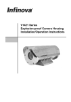
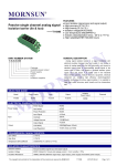
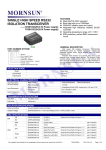
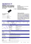
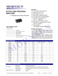
Isolating / Safety Switching Barrier
(Relay Output)
—— TSX00-EX Series
PART NUMBER SYSTEM
TS200-EX
FEATURES
●Fitted devices: 1.NAMUR Sensors;
2. Mechanical Joints.
● Phase-angel and inverse control setting;
● Open circuit detection setting
● Operation Temperature:-25°C to +71°C
● Reliable Performance (MTBF>1,000,000 hours
GENERAL DESCRIPTION
This Isolation Switching Barrier can detect switch or approach
switch’s status in locations where hazardous exists; isolate, transmit
Saf et y barrier m ark
Relay output
Channel number
Signal style
Product seriers
and output it to safe area. Input and output can be set to inverse
control. Approach switch open circuit detection function. Isolation
between Input /Output / Power source.
PRODUCT PROGRAM
Input(Power)
Part number
Output(Hazardous end)
Voltage(VDC)
Typ.
Range
Voltage
Output
(Safe end)
Short Circuit
Current
Typ.
Channel
numbers
TS100
1
TS200
24
18-36
about 8 mA
8 VDC
TS100-EX
2
Relay Output
1
TS200-EX
2
ELECTRICAL SPECIFICATIONS
Common
parameter
Operation voltage
18-36VDC
Input frequency
About 2.0W (with relay output OFF)
Power indicating
LED light (green) ON when operating
Input Signal
Hazardous
Area
Distribution voltage
About 8V (Open status)
Short circuit current
About 8mA
Open circuit threshold current
Safe Area
Switch status of NAMUR sensor,
mechanical joint etc
≤0.1mA
Switching threshold
Typ:1.55mA (hysteresis:0.2mA)
Output signal
Relay output
Response time
≤20mS
Driving capability
250VAC/2A or 30VDC/2A
Load type
Resistive load
(1” ON” joint)
TRANSMISSION SPECIFICATIONS
Under phase-angel control
(K2 K3 OFF )
Input loop current > 2.1mA, relay output close, channel indicator light (red) ON.
Under inverse control
(K2 K3 ON)
Input loop current > 2.1mA, relay output open, channel indicator light (red) OFF.
When connected with NAMUR sensor
Input loop current < 0.05mA, open circuit alarm, channel yellow indicator light ON.
When connected with common
To achieve open circuit detection function, a 10KΩ resistor must be connected to the
switch in parallel.
Input loop current < 1.2mA, relay output open, channel indicator light (red) OFF.
Input loop current < 1.2mA, relay output close, channel indicator light (red) ON.
contact joint switch
Note: K2 is setup channel1 to be reverse or not ,K3 is setup channel2 to be reverse or not
The copyright and authority for the interpretation of the products are reserved by MORNSUN
TSX00-EX
2013.07.01-A/4
Page 1 of 3
ISOLATION SPECIFICATIONS
Five-port isolation
Output ~ Input: 2.5KVAC
Power Supply ~ Input: 2.5KVAC
Power Supply ~ Output: 1.5KVAC
Output 1 ~ Output 2: 1.5KVAC
Input 1 ~ Input 2: 1.5VAC
Electrical isolation
Three-port isolation (Single channel); Five-port isolation(Dual channels)
Isolation strength
2.5KVAC (test for 1minute, humidity < 70%)
EMC
EN61326
STANDARDS & CERTIFICATES
Explosion protection certification mark
[Exia]IIC
Explosion protection certification parameters
Explosion protection certification unit
Explosion protection pass No.
Um=250Vrms, Uo=10.5V, Io=14mA
Po=37mW, Co=1.6uF, Lo=150mH
CHINA NATIONAL QUALITY SUPERVISION AND TEST CENTRE FOR EXPLOSION
PROTECTED ELECTRICAL PRODUCTS
CNEx08.0003
OTHER SPECIFICATIONS
Ambient temperature
Operation temperature:-25°C ~ +71°C
Transport and Storage temperature:-50°C ~ +105°C
Mounting
35mm DIN-rail package, hot plug, thickness: 22.5mm, Plastic UL94-V0
Safety Grade
IP20(IEC60529 / EN60529)
Weight
About 128g
CONNECTION
In intrinsic safety explosion protection systems, isolating barrier belongs to affiliated device. It is installed at safe area, as a connection between
intrinsic safety devices in the hazardous area and non-intrinsic safety devices in the safe area. By limiting the energy to a certain safe amount, it
ensures the safety of in spot devices and people.
Selection regulations for intrinsic safety explosion protection system:
1. The explosion protection grade of the barrier must be equal to or higher than that of in spot intrinsic safety explosion protection device.
2. Take inconsideration of hazardous end output resistance and loop resistance, make sure the barrier’s output voltage meets the minimum
operation voltage requirement of in spot intrinsic safety device.
3. The safety parameters of Barrier’s intrinsic safety end meets:
Uo ≤ UI, Io ≤ Iin, Po ≤ Pin
Co ≥ Cin, Lo ≥ Lin
4. Select suitable Safety barrier which matches the in spot intrinsic safety device for the power’s phase, signal type and transmission mode.
5. Apply necessary protections, avoid influence the in spot intrinsic safety device’s operation from leakage current that generated by safety barrier.
Operation notes:
1. Please read the user manual carefully before using. If any questions please contact our technical support department.
2. Please do not use this product in hazardous area.
3. The power supply of this product should be 24VDC power source. It is forbidden to use 220VAC power supply.
4. To avoid invalid explosion protection function, or any failure, users disassemble this product is forbidden.
APPLICATION CIRCUIT DIAGRAM & PIN DESCRIPTION
Hazardous area
Safe area
14
8
13
7
10
4
9
3
Channel 1
Channel 2
5
DCS
PLC
6
Power
Note: In single model channel 2 is invalid.
The copyright and authority for the interpretation of the products are reserved by MORNSUN
TSX00-EX
2013.07.01-A/4
Page 2 of 3
INSTALLATION & DISASSEMBLY
Installation
DIN35mm standard rail installation:
1.Insert the top of the instrument card in the rail;
2.Push the bottom of the instrument into the rail.
Disassembly
1. Use a screwdriver (Width of edge ≤ 6mm), cut in the metal card lock
from the underside;
2. Boost up the screwdriver and pry the metal card lock downwards;
3. Pull the instrument out of the rail.
3
1
2
PACKAGING DIMENSION & PACKAGING DIAGRAM
Note:
1. All specifications are measured at Ta=25°C, humidity<75%, nominal input voltage and rated output load unless otherwise specified.
2. In this datasheet, all the test setup and methods are based on our corporate standards.
3. All characteristics are for listed models, and non-standard models may perform differently. Please contact our technical support for more details.
4. Please contact our technical support for any specific requirement.
5. Specifications of this product are subject to changes without prior notice.
MORNSUN Science & Technology Co.,Ltd.
Address: No. 5, Kehui St. 1, Kehui development center, Science Ave., Guangzhou Science City, Luogang district, Guangzhou,P.R.China.
Tel: 86-20-38601850
Fax:86-20-38601272
E-mail: [email protected]
Http://www.mornsun-power.com
The copyright and authority for the interpretation of the products are reserved by MORNSUN
TSX00-EX
2013.07.01-A/4
Page 3 of 3