1
P3PC-E967-01EN
fi-5650C Image Scanner
Getting Started
■ Introduction
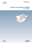
Thank you for purchasing the fi-5650C duplex
color scanner product.
This document describes how to handle fi-5650C
Duplex Color and basic operation methods. Before
you start using the fi-5650C duplex color scanner, be sure to thoroughly read this manual to
ensure correct use.
The “Operator’s Guide” is guide is stored on
the User manual CD-ROM. The guide provides
useful and detailed information on operation,
daily care, replacement of consumables and
trouble shooting, etc. Please also read the
Operator’s Guide for your reference.
• Connect the equipment into an outlet on
a circuit different from that to which the
receiver is located.
• Consult your dealer or an experienced
radio/TV technician.
FCC warning: Changes or modifications not
expressly approved by the party responsible for
compliance could void the user’s authority to
operate the equipment.
ATTENTION
• The use of a shielded interface
cable is required to comply with
the Class B limits of Part 15 of
FCC rules.
• The length of the AC cable must
be 3 meters (10 feet) or less.
■ Regulatory Information
Canadian DOC Regulations
FCC declaration
This digital apparatus does not exceed the
Class B limit for radio noise emissions from
digital apparatus set out in the Radio interference Regulations of the Canadian Department
of Communications.
This equipment has been tested and found to
comply with the limits for a Class B digital
device, pursuant to Part 15 of the FCC Rules.
These limits are designed to provide reasonable
protection against harmful interference in a residential installation. This equipment generates,
uses, and can radiate radio frequency energy
and, if not installed and used in accordance
with the instruction manual, may cause harmful interference to radio communications.
However, there is no guarantee that interference will not occur in a particular installation.
If this equipment does cause harmful interference to radio or television reception, which can
be determined by turning the equipment off
and on, the user is encouraged to try to correct
the interference by one or more of the following measures:
• Reorient or relocate the receiving
antenna.
• Increase the separation between the
equipment and receiver.
This Class B digital apparatus complies with
Canadian ICES-003.
Le pésent appareil numérique n’ément pas de
bruits radioélectriques dépassant les limites
applicables aux appareils numériques de la
classe B prescridtes dans le Réglesment sur le
brouillage radioélectrique dicté par le ministere
des Communications du Canada.
Cet appareil numérique de la classe B est conformme à la norme NMB-003 du Canada.
Bescheinigung des
Herstellers / Importeurs
Hiermit wird bescheinigt, daß der/die/das
fi-5650C
i
In Übereinsstimmung mit den Bestimmungen
der EN45014(CE) funkentstört ist.
Laut Maschinenlärminformationsverordnung
3. GS GV, 18.01.1991:Der höchste
Schalldruckpegel beträgt 70 dB (A) oder weniger gemäß ISO/7779.
International ENERGY STAR®
Program
As an ENERGY
STAR® Partner,
PFU LIMITED has
determined that this
product meets the
ENERGY STAR®
guidelines for energy efficiency.
The International ENERGY STAR® Office
Equipment Program is an international
program that promotes energy saving through
the penetration of energy efficient computers
and other office equipment. The program backs
the development and dissemination of products
with functions that effectively reduce energy
consumption. It is an open system in which
business proprietors can participate voluntarily.
The targeted products are office equipment
such as computers, monitors, printers,
facsimiles, copiers, scanners, and
multifunction devices. Their standards and
logos (
) are uniform among
participating nations.
Use in High-safety
Applications
This product has been designed and
manufactured on the assumption that it will be
used in office, personal, domestic, regular
industrial, and general-purpose applications. It
has not been designed and manufactured for
use in applications (simply called "high-safety
applications" from here on) that directly
involve danger to life and health when a high
ii
degree of safety is required, for example, in the
control of nuclear reactions at nuclear power
facilities, automatic flight control of aircraft,
air traffic control, operation control in masstransport systems, medical equipment for
sustaining life, and missile firing control in
weapons systems, and when provisionally the
safety in question is not ensured. The user
should use this product with adopting measures
for ensuring safety in such high-safety
applications. PFU LIMITED assumes no
liability whatsoever for damages arising from
use of this product by the user in high-safety
applications, and for any claims or
compensation for damages by the user or a
third party.
About the use of mercury
Hg
Lamp(s) inside this product
contain mercury and must be
recycled or disposed of
according to local, state, or
federal laws.
To avoid unexpected injury, read the following
carefully.
Doing the following actions may result in serious personal injuries:
• Do not put the substance in the lamp in
your mouth as it contains mercury.
• Do not incinerate, crush, or shred the
scanner.
• Do not breathe the chemical liquid
contained in the scanner parts.
Trademarks
Microsoft, Windows, and Windows NT are
registered trademarks of Microsoft Corporation
in the United States and/or other countries.
Adobe, the Adobe logo, and Acrobat are either
registered trademarks of Adobe Systems Incorporated in the United States and/or other countries.
ISIS, QuickScan and their respective logos are
trademarks or registered trade marks of Pixel
Translations, a division of Captiva Software
Corporations in the United States.
Other product names are the trademarks or registered trademarks of the respective companies.
How Trademarks Are
Indicated In This Manual
References to operating systems (OS) are
indicated as follows:
Windows 95:
Microsoft® Windows® 95
operating system.
Windows 98:
Microsoft® Windows® 98
operating system.
Windows Me:
Microsoft® Windows® Millennium Edition operating
system.
Windows 2000: Microsoft® Windows® 2000
Professional operating
system.
Windows XP:
Microsoft® Windows® XP
Professional operating
system,
Microsoft® Windows® XP
Home Edition operating
system.
Windows NT:
Microsoft® Windows NT®
Server operating system
Version 4.0,
Microsoft® Windows NT®
Workstation operating
system Version 4.0.
Where there is no distinction between the different versions of the above operating system,
the general term "Windows " is used.
Manufacturer
PFU LIMITED
International Sales Dept., Imaging Business
Division, Products Group
Solid Square East Tower, 580 Horikawa-cho,
Saiwai-ku, Kawasaki-shi Kanagawa 212-8563,
Japan
Phone : (81) 44- 540-4538
All Rights Reserved, Copyright© PFU LIMITED 2004.
■ Note, Liability
READ ALL OF THIS MANUAL
CAREFULLY BEFORE USING THIS
PRODUCT. IF THIS PRODUCT IS NOT
USED CORRECTLY, UNEXPECTED
INJURY MAY BE CAUSED TO USERS OR
BYSTANDERS.
While all efforts have been made to ensure the
accuracy of all information in this manual,
PFU assumes no liability to any party for any
damage caused by errors or omissions or by
statements of any kind in this manual, its
updates or supplements, whether such errors
are omissions or statements resulting from
negligence, accidents, or any other cause. PFU
further assumes no liability arising from the
application or use of any product or system
described herein; nor any liability for
incidental or consequential damages arising
from the use of this manual. PFU disclaims all
warranties regarding the information contained
herein, whether expressed, implied, or
statutory.
iii
■ Preface
Symbols Used In This Manual
Safety Precautions
This manual uses the following symbols in
explanations in addition to warning
indications.
This manual describes important details for
ensuring the safe and correct use of this
product. Thoroughly read this manual before
you start to use this product. In particular, be
sure to read and fully understand the Safety
Precautions described in this manual before
you use this product.
Also, store this manual in a safe place so that it
can be easily referred to during use of this
product.
ATTENTION
This symbol alerts operators to
particularly important information. Be
sure to read this information.
This symbol alerts operators to helpful
advice regarding operation.
HINT
Warning Indications Used In
This Manual
A TRIANGLE symbol indicates
that special care and attention is
required.
The drawing inside the triangle
shows the specific caution.
A CIRCLE with a diagonal line
inside shows action which users
may not perform.
The drawing inside or under the
circle shows the specific action
that is not allowed.
This manual uses the following indications to
ensure safe and correct use of this product, and
to prevent possible danger and injury to the
operator and other persons.
WARNING
This indication alerts operators to an operation
that, if not strictly observed, may result in
severe injury or death.
CAUTION
This indication alerts operators to an operation
that, if not strictly observed, may result in
safety hazards to personnel or damage to
equipment.
iv
R
Outline characters on a colored
background show instructions
users should follow.
It may also include the drawing
that shows the specific instruction.
Warning Labels
This product carries the following label
warning label.
The glass surface inside the ADF
becomes hot during the
operation.
Be careful not to touch the glass
surface inside the ADF.
ATTENTION
Do NOT remove from the scanner, stain
or scratch the warning labels.
■ Safety Precautions
WARNING
The following describes important warnings
described in this manual.
Do not touch the AC cable with wet
hands.
Do not touch the power plug
with wet hands. Doing so might
cause electric shock.
Do not damage the AC cable.
Screen Examples In This
Manual
The screen examples in this manual are subject
to change without notice in the interest of
product improvement.
If the actual displayed screen differs from the
screen examples in this manual, operate by
following the actual displayed screen while
referring to the User's Manual of the scanner
application you are using.
Furthermore, the screenshots in this manual are
for FUJITSU TWAIN 32 scanner driver,
ScandAll 21 Image Capturing Utility Software,
FUJITSU ISIS scanner driver, QuickScan™
image capturing software and Adobe Acrobat.
About Maintenance
The user must not perform repairs on this
scanner.
Contact the store where you purchased the
scanner or an authorized FUJITSU Image
Scanner service provider to make repairs to this
product.
A damaged AC cable may cause
fire or electric shock.
Do not place heavy objects on
AC cables, or pull, bend, twist,
heat, damage or modify AC
cables.
Also, do not use damaged AC
cables or power plugs, and AC
cables or power plugs when the
wall socket is loose.
Use only specified AC cables and
connector cables
Use only specified AC cables
and connector cables. Failure to
use the correct cables might
cause electric shock and
equipment failure.
Use this scanner only at the indicated
power voltage. Do not connect to
multiple-power strips.
Use this scanner only at the indicated power voltage and current. Improper power voltage
and current might cause fire or
electric shock.
Also, do not connect to multiplepower strips.
v
Wipe any dust from the power plug.
Wipe off any dust from metal
parts on the power plug or metal
fittings with a soft, dry cloth.
Accumulated dust might cause
fire or electric shock.
Do not install in locations subject to
oil smoke, steam, humidity, and dust.
Do not install the scanner in
locations subject to oil smoke,
steam, humidity, and dust. Doing
so might cause a fire or electric
shock.
Do not use the scanner if you smell
strange odor.
If you detect heat coming from
the device or detect other problems such as smoke, strange
smells or noises, immediately
turn off the scanner and then disconnect its power plug.
Make sure that the smoking has
stopped, and then contact the
store where you bought the
scanner or an authorized
FUJITSU scanner service
provider.
Turn the scanner OFF if it is
damaged.
If the scanner is damaged for any
reason, turn off the scanner and
unplug the AC cable before
contacting the store where you
purchased the scanner.
Do not put liquids inside the scanner.
Do not insert or drop metal
objects in to the scanner.
Do not scan wet documents or
documents with paper clips or
staples.
Do not splash or allow the scanner to get wet.
vi
If foreign objects (water, small
metal objects, liquids, etc.) get
inside the scanner, immediately
turn off the scanner and
disconnect the power plug from
the power outlet, then contact
the store where you bought the
scanner or the Maintenance
Service Center.
Pay particular attention to this
warning in households where
there are small children.
Do not touch the inside of the
scanner unless necessary.
Do not take apart or modify the
scanner. The inside of the
scanner contains high-voltage
components. Touching these
components might cause fire or
electric shock.
CAUTION
The following describes important cautions
described in this manual.
Do not install the scanner on unstable surfaces.
Install the scanner on a desk so
that none of its parts protrude
outside of the desktop. Also,
make sure that the scanner is
installed on a flat, level surface.
Do not install the scanner on
unstable surfaces. Install the
scanner on a level surface that is
free of vibration to prevent it
from falling.
Install the scanner on a strong
surface that will support the
weight of the scanner and other
devices.
Firmly insert the power plug.
Firmly insert the power plug into
the power outlet as far it can go.
Do not block the ventilation ports.
Do not block the ventilation
ports. Blocking the ventilation
ports generates heat inside of
scanner, which may results in
fire or scanner failure.
Do not place heavy objects or climb
on top of the scanner.
Do not place heavy objects on
the scanner or use the scanner's
top surface for performing other
work. Improper installation
might cause injuries.
Before moving the scanner,
disconnect the power plug from the
power outlet.
Do not move the scanner with
the power and interface cables
connected as this might damage
the cables, causing fire, electric
shock or injuries.
Before moving the scanner, be
sure to disconnect the power
plug from the power outlet, and
disconnect data cables. Also,
make sure that the floor is free of
obstructions.
Do not use the scanner immediately
after moving it from a cold place into
a warm room.
Do not use the device immediately after moving it from a cold
place into a warm room. This
may cause condensation, which
might lead to scanning errors.
Let the device dry about one or
two hours before you use it.
Do not use aerosol sprays near the
scanner.
Do not use aerosol sprays to
clean the scanner. Aerosol
sprays cause dirt and dust to
enter the scanner, resulting
scanner failure and malfunction.
Avoid any contact when scanner is in
use.
Avoid touching any scanner
mechanism when scanning as
this may cause injuries.
Disconnect the power plug from the
power outlet when the scanner is not
used for a long period of time.
When the scanner is not used for
a long period of time, be sure to
disconnect the power plug from
the power outlet for safety.
Do not install the scanner in the
direct sunlight.
Do not install the scanner in the
direct sunlight or near heating
apparatus. Doing so might cause
excessive heat to build up inside
the scanner, causing fire or scanner trouble. Install the scanner in
a well-ventilated location.
Do not try to move or lift the scanner
alone.
This scanner is heavy (77.2lbs/
35kg). When you carry the scanner, ensure that additional personnel are used.
Protect the scanner from static
electricity.
Install the scanner away from
strong magnetic fields and other
sources of electronic noise. Also,
protect the scanner from static
electricity as this might cause the
scanner to malfunction.
vii
viii
Contents
Chapter1
Chapter 2
Appendix
■
Introduction................................................................. i
■
Regulatory Information ............................................... i
■
Note, Liability ............................................................ iii
■
Preface ..................................................................... iv
■
Safety Precautions .................................................... v
PREPARING THE SCANNER..... 1-1
1.1
Checking the contents of scanner package.............1-2
1.2
Names and functions of parts..................................1-2
1.3
Functions of the operator panel...............................1-3
INSTALLATION OF THE SCANNER 2-1
2.1
Installing the scanner...............................................2-2
2.2
Connecting the scanner to your PC.........................2-3
2.3
Installing the Scanner Application ...........................2-4
....................................................AP-1
Appendix 1Troubleshooting ............................................... AP-2
Appendix 2Daily Care ........................................................ AP-7
Appendix 3Replacing Consumables .................................. AP-9
ix
x
Chapter1 PREPARING THE SCANNER
1.1 Checking the contents of scanner package 1-2
1.2 Names and functions of parts ..................... 1-2
1.3 Functions of the operator panel .................. 1-3
1-1
1.1 Checking the contents of
scanner package
When you unpack the scanner package, make sure
that the package contains all the parts on the list
included in the package.
If any parts are missing or defective, contact your
sales representative. Handle the scanner and
accessories with care.
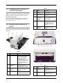
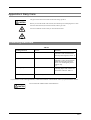
1.2 Names and functions of
parts
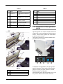
TABLE 1.
No.
Name
Function
5
Side guide
button
Used for adjusting the
side guides.
6
ADF Button
Press this button to open
the ADF.
7
ADF
(Automatic
Document
Feeder)
It transports a document
to the reading position
automatically.
8
Stacker
Scanned documents are
ejected from the ADF
onto this tray. It is
possible to change the
height.
9
Stacker
Extension /
Stopper
Pull out and set the
stopper to the paper
length.
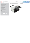
This section describes the names of parts and their
functions .
TABLE 1.
1-2
No.
Name
Function
1
Operator Panel
This panel consists of a
Function No. display,
four operating push
buttons and a LED.
Operation can be
conducted from either of
two sides of the scanner.
Can be closed and
compactly stored when
not in use.
2
ADF Paper
Chute
Holds in place the
document pages / sheets
that feed into the ADF.
No.
Name
Function
3
ADF Paper
Chute
Extension
Please pull out when
scanning a long size
sheet.
10
SCSI Interface
Connector
Used for connecting a
SCSI interface cable
from a PC.
4
Side Guide
It is adjusted to the width
of the paper in order not
to scanned skewed pages.
11
SCSI ID
Switch
Used for setting SCSI ID
(The setting at the factory
shipment is ID=5).
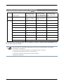
TABLE 2.
TABLE 2.
TABLE 3.
No.
Name
Function
No.
Name
12
USB Interface
Connector
Used for connecting a
USB interface cable from
a PC.
19
Sheet Guide
20
Brake Roller
Power Inlet
Used for connecting a
AC cable from the power
outlet.
21
Pick Arm
22
Plastic Rollers
Used for turning ON/
OFF the scanner.
23
Feed Rollers
24
Ultra Sonic Sensors (Multi feed detection)
25
Glass
13
14
Power Switch
15
Third Party
Slot (Optional
Slot)
The slot for an option
board and extended
memory boards.
16
EXT connector
Connector port for
optional units.
• ADF
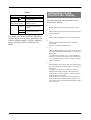
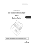
1.3 Functions of the operator
panel
Operator panels are located at both ends of the
scanner for your operating and viewing convenience. Please select a panel side from which
to operate your scanner.
This panel consists of a function number display, buttons and a LED.
Function
(1)
TABLE 3.
No.
Name
17
Chute Roller
18
Pick Roller Set
(2)
Send to
(3)
(4)
Scan
(5)
In addition to English labels for the operator
panel's functions, labels in the following languages are also provided: Chinese, French,
German, Italian and Spanish.
Stick the label on to the clear plastic cover over
the panel to indicate the button's function.
1-3
TABLE 4.
Indications on the
Function No. display
Name
Function
(1)LED
Lights when the scanner
is turned ON.
(2)
Function No. display
Indicates the function No.
and error status.
Buttons
(3)
Function
Changes the Function
activated by the Send to
button .
• 8
(4) Send to
Launches the linked
application software
• P
(5)Scan
For details, refer to the "FUJITSU TWAIN32
Scanner Driver User’s Guide", provided in the
Setup CD-ROM, and the "fi-5650C Operator's
guide", provided in the User Manual CDROM.
The following shows the indications on the
Function No. display.
Blinks only one time upon turning on the scanner.
Indicates that the scanner has been turned ON and is
being initialized.
• 0
Indicates that initialization will soon be completed.
• 1
Indicates that initialization has been completed
successfully.
This status is called "Ready Status".
• U
Indicates that a temporary error (that users can solve)
has occurred during the initialization or scanning of
documents.
"U" and an error number (0, 1, 2, 4) are displayed
alternately. To return the scanner to the ready status
("1"), press the "Scan" or "Send to" button while the
error is indicated.
• E
Indicates that a device alarm (that users cannot solve)
has occurred during the initialization or scanning of
documents.
"E" and an "alarm code" (a number or letter) are
indicated alternately. To return the scanner to the
ready status ("1"), press "Scan" or "Send to" button
while the alarm is indicated.
If this alarm occurs, turn the power off and then on
again. If the alarm is indicated after turning on the
power again, contact an authorized FUJITSU scanner
service provider.
1-4
Chapter 2 INSTALLATION OF THE
SCANNER
2.1 Installing the scanner .............................................2-2
2.2 Connecting the scanner to your PC .......................2-3
2.3 Installing the Scanner Application..........................2-4
2-1
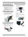
2.1 Installing the scanner
1.
Place the scanner at its installation site.
This scanner can be placed with the ADF
paper chute facing either right or left side of
the installing location.
For details on the scanner’s dimensions
and required installation space, refer to "10
SCANNER SPECIFICATION" in the "fi5650C Operator's guide".
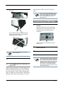
2.
4.
Connecting the AC cable.
Open the cable cover located below the
ADF paper chute and insert the AC cable
into the power inlet.
Cable
cover
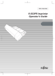
Setting the ADF Paper Chute.
Hold the ADF paper chute and insert
its tabs into the holes on the rear side
of the ADF as shown in the figure
below so that the side guides facing
upwards.
Once the cable is connected, close the
cable cover.
Lead out the AC cable from the conduit
located at the bottom of both sides of the
cable cover.
<When leading out the AC cable from the
right side>
3.
Setting the Stacker
Mount the Stacker onto the scanner
aligning the protrusions to the holes on the
scanner.
You can fix the stacker at two positions: the
upper position or the lower position.
2-2
<When leading out the AC cable from the
left side>
with either the USB or the SCSI interface
cable.
ATTENTION
Do not connect both the USB interface
cable and the SCSI cable at the same
time. It is not possible to use the USB
interface with Windows 95 and/or
WindowsNT 4.0.
Connecting the USB Cable
1.
Please connect a USB cable to the
Scanner.
Open the cable cover located below the
ADF paper chute and connect the USB
interface cable to the USB interface
connector.
Do not lead out the AC cable as shown
below, since the cable cover may pinch
and damage the AC cable.
Once the cable is connected, close the
cable cover.
ATTENTION
5.
Use only the AC cable included the
scanner package.
Connect the AC cable to a power outlet.
2.2 Connecting the scanner to
your PC
2.
Please connect the other end of the
cable to your PC.
3.
Turn ON the scanner.
4.
Turn ON your PC.
ATTENTION
Use the USB interface cable provided as
an accessory for the scanner. Operation
with a commercially available USB cable
is not guaranteed. When connecting to a
USB hub, be sure to connect to the hub
nearest your computer (first stage). If
you connect it to a USB hub from the
second stage onwards the scanner may
not operate correctly.
When running Windows 95 and/or Windows
NT 4.0, connect the scanner to your PC with
the SCSI interface cable. When running Windows 98, Windows Me, Windows 2000 and/or
Windows XP, connect the scanner to your PC
2-3
The SCSI has to fit to a 50 Pin half pitch connector
and the SCSI card connector of your PC.
• SCSI card
Use the recommended SCSI card noted on the following website:
1.
Turn the scanner OFF.
2.
Set the SCSI ID.
Open the cable cover located below the
ADF paper chute and set the device
address by using the SCSI ID switch.
http://imagescanner.fujitsu.com/
4
0
7
456
8
1
1.
5 6
7
When connecting the SCSI interface
cable, be sure to first connect the SCSI
interface cable then turn on the scanner
and your PC. Connect the scanner so
that it is the terminated device on the
SCSI daisy chain.
2 3
ATTENTION
23
• SCSI cable
The factory default setting for SCSI ID is "ID 5". If the
SCSI ID of another device has already been set to the
same ID, change either the scanner's SCSI ID or that of
the other device. To change the SCSI ID see the
following procedure.
1
When using the scanner with the SCSI interface, you need to purchase a commercially
available SCSI cable and a SCSI card.
Setting the SCSI ID
9
Connecting the SCSI
interface cable
0
Connect the SCSI cable to the scanner.
Open the cable cover located below the
ADF paper chute, connect the SCSI cable
to the SCSI interface connector and make
sure it is firmly connected.
TABLE 1.
No.
Description:
0-7
Can be set as the ID.
8, 9
Used for the factory default value
(SCSI ID=5).
3.
Turn ON the Scanner.
When the scanner is turned ON, the SCSI
ID set at step 2 is enabled.
Once the cable is connected, close the
cable cover.
ATTENTION
2.
HINT
Be careful not to bend the pins of the
SCSI cable when connecting to the
scanner .
Connect the other end of the cable to
your PC.
For setting the SCSI ID of the scanner,
please refer to the following section.
4.
Turn ON your PC.
2.3 Installing the Scanner
Application
For scanning documents with this scanner, the
scanner driver as well as an image capturing
application software (called "application" hereafter) must be installed on your PC.
Scanner driver:
FUJITSU TWAIN 32 Scanner Driver
FUJITSU ISIS Scanner Driver
2-4
Application:
ScandAll 21 (for TWAIN)
QuickScan Pro (for ISIS)
2.3.1 For Fujitsu Twain 32
Scanner Driver
Preparation
Before installing the application, please
confirm the following items:
• Keep the Setup CD-ROM at hand.
• Confirm if the scanner is connected to
your PC correctly.
• If an older version of the FUJITSU
TWAIN 32 Driver has already been
installed, please uninstall it before
installing the new one.
• There are two types of FUJITSU TWAIN
32 Drivers. Depending on the operating
system (OS) of the computer, the most
appropriate driver will be installed
automatically.
Installing the FUJITSU
TWAIN32 Scanner Driver
HINT
Windows XP screenshots are used in
this section. The windows and operations may slightly vary depending on
your OS.
1.
Turn the scanner ON.
2.
Turn on your PC and log on to
Windows.
ATTENTION
HINT
When using Windows NT 4.0, Windows
2000 or Windows XP, log on as a user
with "Administrator" privileges (privileges
of the administrator of your PC)
The scanner may be detected
automatically. If so, [Found New
Hardware Wizard] (or [Add/Remove
Hardware Wizard]) dialog box will
appear. Click [Cancel] to close the
Wizard window.
• For Windows 98, Windows Me,
Windows 2000, Windows XP:
FUJITSU TWAIN32 V9
• For Windows 95 and Windows
NT 4.0:
FUJITSU TWAIN32 V8
• When using Windows 95 or Windows
NT 4.0: ASPI Manager 4.01 or later is
required (generally comes with SCSI
board products).
HINT
ATTENTION
For details on connecting the scanner,
refer to "2.1 Installing the scanner" on
page 2 in this manual.
Uninstall [Scanner Utility for Microsoft
Windows] in [Add/Remove Programs] of
the control panel.
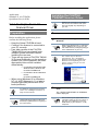
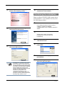
3.
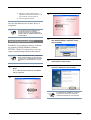
Insert the Setup CD-ROM into the CD
drive.
The <SETUP DISK START UP SCREEN>
will be displayed.
ATTENTION
This screen may not appear when the
"Autoplay" setting of your PC is OFF. In
this case, run "Install.exe" in this CDROM directly by the "Explorer" or "My
Computer".
2-5
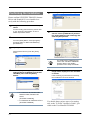
4.
Click [INSTALL PRODUCTS].
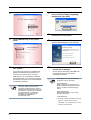
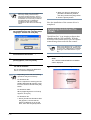
7.
Select a language used for installation on [Choose Setup Language]
window and click [OK].
8.
Install the application following the
instructions on the window.
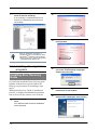
5.
Click [TWAIN Driver] on the window
below.
9.
When the [InstallShield Wizard Complete] window appears, click [Finish].
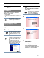
6.
Error Recovery Guide Installation window appears.
10.
Your computer is restarted and the
scanner will be detected.
Error Recovery Guide is a software that
displays troubleshooting information on
screen if any scanner error occurred.
Although you do not install this software,
the performance of the scanner would not
be affected. However it is recommendable
to install this software.
ATTENTION
When you select [Yes] for installing Error
Recovery Guide, [Choose Setup
Language] window appears. Select a
language and follow the instructions on
the window. Error Recovery Guide will
automatically start on finishing its
installation. Please wait until the
installation of TWAIN driver
automatically starts.
Do not remove the Setup CD-ROM from
the CD drive until your PC will be
completely restarted.
ATTENTION
Depending on the OS, the following
operations may be necessary.
For Windows 98:
When a request for inserting the CDROM of Windows 98 appears, insert it
into the CD drive and click the [OK]
button.
For Windows 2000:
When [Digital Signature not Found]
appears, click [Yes].
For Windows XP
1.
2-6
When [Found New Hardware Wizard]
appears, confirm that the Setup
CD-ROM is set in the CD drive, then
click the [Next] button.
2.
When any alarm is displayed on
[Hardware Installation] window, click
the [Continue Anyway] button.
3.
Click the [Finish] button.
3.
Click [ScandAll 21].
4.
Select an appropriate language from
the <Choose Setup Language> menu
and click [OK].
5.
Install the application following the
instructions on the screen.
6.
When [InstallShield Wizard Complete]
screen is displayed, click [Finish].
Now the installation of the scanner driver is
completed.
ATTENTION
For confirming if the installation was
successful, perform a scanning
operation by using an application that
complies with the TWAIN standard such
as ScandAll 21.
Installing ScandAll 21
ScandAll 21 is an imaging software, conforming with the TWAIN standards. With the
FUJITSU TWAIN 32 scanner driver you can
capture scanned image data from the scanner.
ATTENTION
1.
When using Windows NT 4.0, Windows
2000 and/or Windows XP, please login
as a user with "Administrator" privileges
(privileges of the administrator of your
PC).
Insert the Setup CD-ROM in your CDdrive
The, <SETUP DISK STARTUP SCREEN>
will be displayed.
2.
Click [INSTALL PRODUCTS].
ATTENTION
For finishing the installation, it may be
necessary to restart your computer.
Follow the instructions on the window.
2-7
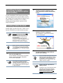
Confirming the installation
5.
Select [To View] from the [scan] menu.
6.
Set the scanning resolution, document
size etc. on the [TWAIN driver] window
(for setting details of the scanning) and
click the [Scan] button.
Please confirm if FUJITSU TWAIN32 Scanner
Driver and ScandAll 21 were installed correctly with the following procedure.
1.
Set your documents into the ADF Paper
Chute.
For the loading of documents, please refer
to 2.3 "Scanning documents" of the "fi5650C Operator's Guide".
2.
Start ScandAll 21
From the [Start] Menu, select [Program][Scanner Utility for Microsoft Windows][ScandAll 21].
3.
Specify the scanner to be used
Select [Select Source] from the [Scan]
menu.
HINT
4.
In the displayed dialog box, please
select [FUJITSU fi-5650Cdj] or [FUJITSU
TWAIN32], then click the [Select]
button.
7.
For details about [TWAIN driver],
refer to the "FUJITSU TWAIN32
Scanner Driver User Guide"
provided on the Setup CD-ROM
The document is scanned and it’s
image will be displayed on the ScandAll
21 screen.
If the scanning is performed successfully,
the installation has been finished.
• For Windows 98, Windows Me,
HINT
Windows 2000, Windows XP
select:
[FUJITSU fi-5650Cdj]
• For Windows 95, Windows NT 4.0:
[FUJITSU TWAIN32]
2-8
For details about various types of scanning,
refer to the "fi-5650C Operator's Guide", provided on the User Manual CD-ROM.
2.3.2 For Fujitsu ISIS Scanner
Driver
3.
The <SETUP DISK STARTUP SCREEN>
will be displayed.
Preparation
Please confirm the following items before
installing the ISIS driver:
• Setup CD-ROM
• Confirm if the scanner is connected correctly to your
PC.
HINT
Insert the Setup CD-ROM into the CD
Drive.
ATTENTION
This screen may not be displayed when
the, “Autoplay” setting of your PC is
turned off. In this case, please run
"Install.exe" on the CD-ROM directly
from explorer or "My Computer".
4.
Click [INSTALL PRODUCTS].
5.
Click [ISIS Driver].
6.
The Error Recovery Guide Installation
window appears.
About connecting your scanner to the
PC, please refer to "2.1 Installing the
scanner" on page 2" of this manual.
Installing FUJITSU ISIS
scanner driver
1.
Turn on the scanner.
2.
Turn your PC on an log on to Windows.
ATTENTION
HINT
When using Windows NT 4.0, Windows
2000 and/or Windows XP, please login
as a user with "Administrator" privileges
(privileges of the administrator of your
PC).
In this manual, Windows XP screens are
used. The screens and operations
might differ slightly depending on your
OS.
The scanner is automatically detected
and "A detection wizard of the new
hardware " or "An addition wizard of new
hardware" may be displayed. Please
click the [cancel] button and close the
wizard screen. (* The screen might differ slightly depending on your OS)
Error Recovery Guide is a software
providing you with troubleshooting
information displayed on the screen when
a scanner error occurs. Not installing this
software will not have an effect on the
performance of the scanner. However it is
recommended to install this software.
2-9
ATTENTION
7.
When you select [Yes] for installing Error
Recovery Guide, [Choose Setup
Language] window appears. Select a
language and follow the instructions on
the window. Error Recovery Guide will
automatically start on finishing its
installation. Please wait until the
installation of ISIS driver automatically
starts.
Select an appropriate language used for
the installation from the <Choose Setup
Language> window and click [OK].
2. When any alarm is displayed on
[Hardware Installation] window,
click the [Continue Anyway] button.
3. Click the [Finish] button.
Now the installation of the scanner driver is
completed.
Installing QuickScan Pro
(Trial)
"QuickScan Pro" is an imaging software that
complies with the ISIS standards. With the
FUJITSU ISIS scanner driver you can capture
scanned image data read with the scanner.
ATTENTION
8.
9.
10.
Install the application following the
instructions on the window.
When the [InstallShield Wizard Completed] appears, click on [Finish].
The system is restarted and the scanner will be detected.
Do not remove the Setup CD-ROM until
the PC is restarted completely.
ATTENTION
Depending on the OS, the following
operations may be necessary.
For Windows 98:
When a request for inserting the CDROM of Windows 98 appears, insert
it into the CD drive and click the [OK]
button.
For Windows 2000:
When [Digital Signature not Found]
appears, click [Yes].
For Windows XP:
1. When [Found New Hardware Wizard] appears, confirm that the
Setup CD-ROM is set in the CD
drive, then click the [Next] button.
2-10
1.
When using Windows NT 4.0, Windows
2000 and/or Windows XP, please login
as a user with "Administrator" privileges
(privileges of the administrator of your
PC).
Insert the Setup CD-ROM into the CD
drive.
The <SETUP DISK STARTUP SCREEN>
will be displayed.
2.
Click [INSTALL PRODUCTS].
3.
Click the [QuickScan PRO (trial)]
button in the following screen.
6.
Install the application following the
instructions on the window.
Confirming the installation
Please confirm if FUJITSU ISIS scanner driver
and ScandAll 21 were installed correctly with
the following procedure
1.
4.
Load the documents on the scanner.
For loading documents, please refer to
Chapter 2 "BASIC SCANNER
OPERATIONS" of the "fi-5650C Operator's
Guide".
Install the application following the
instructions on the window.
2.
Start QuickScan Pro.
Please select [Start], [Programs],
[QuickScan] in turn, then click on
[QuickScan].
5.
ATTENTION
3.
Select [Scan], and [Select Scanner...]
from the menu bar.
4.
Select Fujitsu fi-5650C, then click the
[OK] button.
5.
Select [Preview Setting...] from the
[Scan] menu.
6.
Set the reading resolution and document size, then click [OK].
Input the requested information and
click on the [Next] button.
QuickScan Pro, attached to the Setup
CD-ROM is a trial version. Therefore,
there is a limitation of 30 program starts.
Purchasing this software is necessary if
you intent to use this software unlimited.
(when installing and using the trial
version, please use the displayed serial
number. For the operations of
QuickScan, please refer to the
"Overview of QuickScan" or the
"QuickScan Help". Please click [Start],
[Program], and then [QuickScan] in turn,
and select then the file to refer.
2-11
7.
Select [Preview Scan] from the [Scan]
menu to start the scanning-
2.
Click [INSTALL PRODUCTS].
3.
Click [Error Recovery Guide] in the following screen.
4.
Select a language to use for the installation in the <Choose Setup Language>
window and click [OK].
5.
Install the application following the
instructions on the window.
6.
When the [InstallShield Wizard Complete] screen is displayed, click [Finish].
If the scanning is completed without any
troubles, the installation was performed
successfully.
HINT
Refer to "QuickScan Overview" or
"QuickScan Help" for information about
QuickScanTM functions and operations.
On the [Start] menu, point to [Programs]
- [QuickScan] and click the file.
2.3.3 Installing other application
programs
Installing Error Recovery
Guide
If you did not install the Error recovery guide
together with the driver, please follow the
below given procedure for installing it separately.
When Error Recovery Guide is installed on
your PC, it displays troubleshooting information on screen if any scanner error occurred.
1.
Insert the Setup CD-ROM in your CD
drive.
The <SETUP DISK STARTUP SCREEN>
will be displayed.
2-12
Installing the Image
processing software option
(trial version)
2.
Click the [Install] button when the
following screen is displayed. Then
click the [Install Acrobat 6.0 Standard]
button.
3.
Click the [Next] button when the
following screen is displayed.
For the installation of the image processing
software option (trial version), please refer to
the "Image Processing Software Option User's
Guide"which is stored at [User’s Guide] [Image processing software option] in the
Setup CD-ROM.
Installing Adobe Acrobat
Install Adobe Acrobat from the "Adobe Acrobat 6.0 CD-ROM" provided with this scanner.
ATTENTION
HINT
Adobe Acrobat 6.0 Standard is not
supported by Microsoft Windows 95,
Microsoft Windows NT4.0, Microsoft
Windows 98, Microsoft Windows Me.
(Except for Microsoft Windows 98
Second Edition.)
To use Acrobat 6.0 with FUJITSU
scanners, FUJITSU TWAIN32 Scanner
Driver Version 8.11.32 or later, or
Version 9.11.32 or later is required.
The installation is started and its setup
screen is displayed.
Adobe Acrobat is required for displaying
the manuals stored on the CD-ROM.
* The installation of Adobe Acrobat 6.0
is not necessary if it is already installed
on your PC.
4.
1.
Insert the Adobe Acrobat 6.0 CD-ROM
into your CD-ROM drive.
The CD-ROM is automatically recognized
and the "Adobe Acrobat6.0 AutoPlay"
screen will be displayed.
ATTENTION
The <Adobe Acrobat 6.0 AutoPlay>
screen may not appear when the
“Autoplay” setting of your PC is turned
off. In this case, run" AutoPlay.exe" on
the CD-ROM directly from the explorer
or "My Computer".
HINT
ATTENTION
After the setup screen is displayed, follow the instructions on the screen to
perform the installing.
For more detailed information about the
Adobe Acrobat 6.0 installation, please
read "Read me" displayed at the screen
of operation 2. For the operations of
Adobe Acrobat 6.0, please refer to the
"Adobe Acrobat 6.0 help".
Support and User registration for
Adobe products
For details, refer to the technical support
information stored in the [Customer
Support] folder on Adobe Acrobat 6.0
Standard CD-ROM. (Note that free
person-to-person support is not
available for this is bundled product.)
2-13
2-14
Appendix
Appendix 1 Troubleshooting .......................... AP-2
Appendix 2 Daily Care ................................... AP-7
Appendix 3 Replacing Consumables ............ AP-9
AP-1
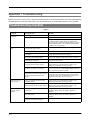
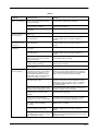
Appendix 1 Troubleshooting
Before you ask for repair service, check the following items. If the problem persists even after implementing
remedies below, contact the dealer where your purchased the or an authorized FUJITSU service provider.
Troubleshooting checklist
TABLE 1.
Symptom
Check this Item
Remedy
Scanner cannot be
tuned ON.
Did you push the power switch?
Push the power switch.
Is AC cable connected correctly?
Correctly connect the AC cable.
Disconnect the AC cable from the scanner, then
connect it again. If this does not restore the
power supply, contact the dealer where you purchased the scanner or an authorized FUJITSU
scanner service provider.
Scanning does not
start.
Indication on the
Function No. display goes out.
Vertical lines appear
in the scanned
images.
AP-2
Are the documents loaded correctly
on the ADF paper chute?
Load the document correctly on ADF paper chute.
Is the ADF closed completely?
Close the ADF completely.
Is the interface cable connected
correctly?
Correctly connect the cable. (When a USB hub is
used, check the hub’s power supply.)
Is the interface cable broken?
Use a new interface cable and correctly connect it.
Is the SCSI ID set correctly? (When
using SCSI interface)
Set the SCSI ID correctly using SCSI ID switch on
the rear of the scanner.
Does the scanning start after
running ON the scanner again?
If this does not solve the problem, contact the
dealer where you purchased the scanner or an
authorized FUJITSU service provider.
Does the Function No. display
indicates an alarm or an error?
When the Function No. display indicates an alarm
or an error, refer to "6 TROUBLE SHOOTING" in
the "fi-5650C Operator's Guide".
Does the alarm state remain
displayed even after the scanner has
been turned OFF and back ON
again?
Turn OFF and ON the scanner.
If this does not eliminate the alarm state, contact
the dealer where you purchased the scanner or an
authorized FUJITSU service provider.
Does the display remain blank even
after you push any button on the
operator panel?
If this does not solve the problem, contact the
dealer where you purchased the scanner or an
authorized FUJITSU service provider.
Does the display remain blank even
after running ON the scanner again?
If this does not solve the problem, contact the
dealer where you purchased the scanner or an
authorized FUJITSU service provider.
Do the lines appear on the same part
of images?
Clean the glass following the instruction in “4.2
Cleaning ADF” of the “fi-5650C Operator’s
Guide”.
Are the upper/lower glasses inside
the ADF clean?
Clean the glass following the instruction in “4.2
Cleaning ADF” of the “fi-5650C Operator’s
Guide”.
Do the lines disappear on images
with low resolution settings?
Scan the documents with low resolution settings.
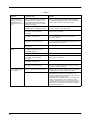
TABLE 1.
Symptom
Check this Item
Remedy
The scanned image
shifts or is distorted.
Is the ADF cover pressed down or
heavy object placed on the ADF
during scanning?
Do not press down the ADF nor place heavy
objects on the ADF during scanning.
Is something causing the scanner to
vibrate during scanning?
Do not allow anything to cause the scanner to
vibrate while scanning.
Are the documents loaded
correctly?
Load the documents correctly.
Quality of scanned
pictures or photos is
not satisfactory.
Did you select half toning or
dithering?
Select half toning or dithering on your PC.
Are the upper/lower glasses inside
the ADF clean?
Clean the glass following the instruction in “4.2
Cleaning ADF” of the “fi-5650C Operator’s
Guide”.
Quality of scanned
text or lines is not
satisfactory.
Are the upper/lower glasses inside
the ADF clean?
Clean the glass following the instruction in “4.2
Cleaning ADF” of the “fi-5650C Operator’s
Guide”.
Images are distorted
or blurred.
Are the documents loaded
correctly?
Load the documents correctly.
Are the upper/lower glasses inside
the ADF clean?
Clean the glass following the instruction in “4.2
Cleaning ADF” of the “fi-5650C Operator’s
Guide”.
Is the ADF cover pressed down or
heavy object placed on the ADF
during scanning?
Do not press down the ADF or place heavy object
on the ADF during scanning.
Is something causing the scanner to
vibrate during scanning?
Do not allow anything to cause the scanner to
vibrate while scanning.
Is the scanner installed on a flat,
level surface?
Install the scanner on a flat, level surface.
Do the documents qualify the
"Document Quality" and "Doublefeed Detection Condition" in "8
DOCUMENT SPECIFICATON
FOR THE ADF" of the "fi-5650C
Operator's Guide" fi-5650C?
Use the documents that qualify the "Document
Quality" and "Double-feed Detection Condition"
in "8 DOCUMENT SPECIFICATON FOR THE
ADF" of the "fi-5650C Operator's Guide".
Are the documents set properly on
the ADF paper chute?
Fan the documents before scanning. Correctly
align the document stack and load them on the
ADF paper chute. For details, refer to "2 BASIC
SCANNER OPERATIONS" of the "fi-5650C
Operator's Guide".
Were the documents fanned before
loaded onto the ADF paper chute?
Fan the documents before loading, or reduce the
number of sheets of the documents.
Have the documents just been
printed out by a copier or laser
printer?
Fan the documents 3 or 4 times to remove static
electricity from the paper.
Is the document stack over: 20mm
(0.79 in)? (for A4 size paper)
10mm (0.4 in)? (for A3 size paper)
Reduce the number of sheets in the document stack
to 20mm (0.79 in) (for A4 size paper) or 10mm
(0.4 in) (for A3 size paper) thickness or less.
Are all the consumables (Pick roller
set, Brake roller) installed
correctly?
Correctly install the consumable(Pick roller set,
Brake roller), if needed.
Is any of the consumables (Pick
roller set, Brake roller) dirty?
Clean all the consumables. For details, refer to "4
DAILY CARE" of the "fi-5650C Operator's
Guide"
Is any of consumables (Pick roller
set, Brake roller) worn out? Check
the consumable counter.
Replace the consumables. For details, refer to "5
REPLACING CONSUMABLES" of the "fi-5650C
Operator's Guide"
Double-feed errors
occur frequently.
AP-3
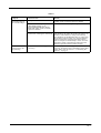
TABLE 1.
Symptom
Check this Item
Remedy
Documents are not
fed into the ADF
(pickup error occurs
frequently or the
document stops midway).
Do the documents qualify the
"Document Quality" and "Doublefeed Detection Condition" in "8
DOCUMENT SPECIFICATON
FOR THE ADF" of the "fi-5650C
Operator's Guide"?
Use the documents that qualify the "Document
Quality" and "Double-feed Detection Condition"
in "8 DOCUMENT SPECIFICATON FOR THE
ADF" of the "fi-5650C Operator's Guide".
Were the documents fanned before
loaded onto the ADF paper chute?
Fan the documents before loading, or reduce the
number of sheets of the documents.
Are all the consumables (Pick roller
set, Brake roller) installed
correctly?
Correctly install the consumable(Pick roller set,
Brake roller), if needed.
Is any of consumables (Pick roller
set, Brake roller) dirty?
Clean the dirty consumables. For details, refer to
4.2 "Cleaning the ADF" of the "fi-5650C
Operator's Guide".
Is any of consumables (Pick roller
set, Brake roller) worn out?
Replace the consumable if needed. For details,
refer to 5 "REPLACING CONSUMABLES" of the
"fi-5650C Operator's Guide".
Is there any debris on the document
feed path?
Remove any debris from the document feed path.
Do the documents satisfy the
conditions described in "8.2
Document Quality"?
Use documents that satisfy the requirements.
Is there any debris in the ADF?
Clean the ADF or remove debris from the ADF.
Are all the consumables (Pick roller
set, Brake roller) installed
correctly?
Correctly install the consumable (Pick roller set,
Brake roller) , if needed.
Is any of consumables (Pick roller
set, Brake roller) dirty?
Clean the dirty consumable.
Is any of consumables (Pick roller
set, Brake roller) worn out?.
Replace the consumable if needed. For details,
refer to 5.3 "Replacing the pick roller set" of the
"fi-5650C Operator's Guide".
Did you cleaned all of the rollers?
Clean all the rollers. For details, refer to "4 DAILY
CARE" of the "fi-5650C Operator's Guide"
Did you adjust the scan scale?
For Windows 98, Windows Me, Windows 2000
and Windows XP, please select [Scanner and
Camera] in the [Control Panel], then click [Device
Set] tab to adjust the scan scale.
For Windows 95 and Windows NT 4.0, right-click
Scanner Control Center icon in task tray, select
[Option] and adjust the scan scale. Please refer to
“7 Online Setup” of the “fi-5650 Operator's Guide”
and adjust the offset from the Software Operation
Panel (online settings).
Paper jams occur frequently.
The scanned images
are elongated.
AP-4
TABLE 1.
Symptom
Check this Item
Remedy
There is a shadow on
the leading edge of
the scanned images.
Did you cleaned all of the rollers?
Clean all the rollers. For details, refer to "4 DAILY
CARE" of the "fi-5650C Operator's Guide"
Do the documents qualify the
"Document Quality" in "8
DOCUMENT SPECIFICATON
FOR THE ADF" of the "fi-5650C
Operator's Guide"?
Use documents that satisfy the requirements.
Did you adjust the offset? (Starting
position for scanning the document)
For Windows 98, Windows Me, Windows 2000
and Windows XP, adjust the [Sub-scan Setting\ on]
Scanners and Cameras\ in the [Control Panel].
For Windows 95 and Windows NT 4.0, right-click
the Scanner Control Center icon, select [Options] [Sub-scan Setting] and adjust the offset. Please
refer to Chapter 7 “Online Setup” of the “fi-5650
Operator's Guide” and adjust the offset from the
Software Operation Panel (online settings).
Did you install the ADF paper chute
correctly?
Please verify that the ADF paper chute is installed
correctly. For details on the installation of the ADF
paper chute, refer to section 2.1, “Installing the
scanner,” on page 2.
The ADF makes
strange noises during scanning.
AP-5
Temporary Error
TABLE 3.
Indication
Meaning
E2
Optical error (ADF front).
E3
Optical error (ADF back).
E4
Motor fuse malfunction.
E5
Lamp fuse malfunction.
E6
Operator panel malfunction.
E7
EEPROM malfunction.
E8
SCSI interface fuse
malfunction.
E9
Image memory malfunction.
EA
Imprinter malfunction. (*)
The following shows the procedure for
resolving of each temporary error.
Ec
Memory malfunction.
Ed
Malfunction at SCSI interface
controller.
• "U1" error
EF
Background switching
mechanism malfunction.
E10
ROM malfunction.
E11
Fan malfunction.
E12
Heater malfunction.
E15
Malfunction in the additional
memory option.
E16
Option board malfunction.
E17
Imprinter fuse malfunction. (*)
E18
Sensor malfunction.
E19
LSI malfunction.
E1A
Internal communication
malfunction.
TABLE 2.
Indication
Meaning
U1
A paper feed error occurred.
U2
A double feed error occurred.
U4
The ADF cover is opened.
U6
The print cartridge is not
installed. (*)
U7
A paper detection
failure has occurred at
Imprinter.(*)
Remove jammed documents.
Confirm that the documents meet the paper
conditions for scanning.
Refer to Chapter 6 "TROUBLE SHOOTING" in the
"fi-5650C Operator's Guide".
• "U2 " error
Remove jammed documents
Confirm that the documents meet the paper
conditions for scanning.
Refer to "8 DOCUMENT SPECIFICATION OF
ADF" of the "fi-5650C Operator's Guide".
• "U4" error
Close the ADF cover completely.
For details, refer to “6 TROUBLESHOOTING” in
the “fi-5650C Operator’s Guide”.
* "U6" and "U7" are temporary errors related with the
Imprinter option (sold separately)
* "EA" and "E17" are alarms related with the
Imprinter option (sold separately).
About Error Recovery Guide
Device alarm
(Permanent error)
When you encounter any alarm, turn OFF and
ON the scanner. If the alarm is still displayed
on the Function No. display, contact the dealer
where you purchased the scanner or an
authorized FUJITSU scanner service provider.
AP-6
HINT
When this software is installed on your
PC, the icon appears in the task tray
when Windows is started up. If any
device alarm or temporary error
occurred, the Error Recovery Guide window appears and displays information
such as error names and error codes
regarding the alarm. Record the information and click [Details...] to know more
detailed information for trouble shooting.
Appendix 2 Daily Care
The glass of the inside of the ADF becomes hot during operation.
CAUTION
Before you clean the inside of the scanner, turn OFF the power and unplug the AC cable
from the outlet and wait (at least three minutes) until it gets cold.
Do not turn OFF the scanner when you clean the Feed rollers.
Cleaning Materials
TABLE 4.
Cleaning Materials
Part No.
Remarks
Cleaner F1
CA99501-0013
1 bottle.
Moisten a cloth with this fluid
and wipe the respective areas. *1
Cleaner F2
CA99501-0014
1 bottle.
Moisten a cotton swab with this
fluid and clean the respective
areas. For cleaning the plastic
rollers only.
*1
Cleaning Paper
CA99501-0012
10 sheets / package. Moisten a
Cleaning Paper with Cleaner F1
and insert it into the ADF. *1
Lint-free dry cloth
Commercially available one.
*1) For details on the cleaning materials, contact the FUJITSU scanner dealer where you purchased the scanner.
Do not clean the rubber rollers with Cleaner F2.
CAUTION
AP-7
Locations and Cycle for Cleaning
TABLE 5.
Names of parts
ADF
Chute Roller
Pick Arm
Pick Roller Set
Brake Roller
Feed Rollers
Plastic Rollers
Sheet Guide
Glass
Ultrasonic Sensor
Standard Cleaning
Cycle using Cleaner
F1
Standard Cleaning
Cycle using Cleaning
Paper with Cleaner F1
Standard Cleaning
Cycle using Cleaner
F2
Clean these parts
after every 10,000
scans.
Clean these parts
after every 10,000
scans.
When stains are persistent.
3
3
3
3
3
3
3
3
3
3
3
3
3
Clean this part with a dry lint-free dry cloth.
For details on the cleaning the ADF, refer to Chapter 4 "DAILY CARE OF THE EQUIPMENT" of
the "fi-5650C Operator Guide".
ATTENTION
The scanner must be cleaned more frequently if you scan any of the following type of documents.
•
•
•
•
•
AP-8
Documents of coated paper.
Documents that are almost completely covered with printed text or graphics.
Chemically treated documents such as carbonless paper
Documents containing a large amount of calcium carbonate
Handwritten documents
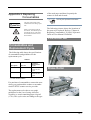
Appendix 3 Replacing
Consumables
of the used paper and how frequently the
scanner is used and cleaned.
ATTENTION
CAUTION
Use only the specified consumables.
The glass of the inside of the
ADF becomes hot during operation.
When you clean the inside of
the scanner, turn OFF the power
and unplug the AC cable from
the outlet and wait for at least
three minutes.
The following pictures shows the locations of
the parts to be replaced. Refer to "Chapter 4
Replacing Consumables" fi-5650C Operator's
Guide on User Manual CD-ROM.
Pick Roller Set
Consumables and
Replacement Cycle
The following table shows the specifications
of consumables and guidelines for the
replacement cycle.
TABLE 6.
Standard
Replacement
Cycle
Description
Part No.
Brake Roller
PA03338-K010
After 250,000
scans or one
year.
Pick Roller*
PA03338-K011
After 250,000
scans or one
year.
Brake Roller
* A set of two rollers.
For purchase of consumables, contact the store
where you purchased the scanner or an authorized FUJITSU scanner service provider.
The replacement cycles above are rough
guidelines for the case of using A4/Letter
woodfree or wood containing paper 64 g/m2
(17 lb). This cycle varies according to the type
AP-9
fi-5650C Image Scanner Getting Started
P3PC-E967-01EN
Date of issuance: May, 2004
Issuance responsibility: PFU LIMITED
z Copying
of the contents of this manual in whole or in part and copying of the scanner
application is forbidden under the copyright law.
z The contents of this manual are subject to change without notice.
z PFU LIMITED is not liable whatsoever for any damages resulting from use of this scanner and procedures described in this manual, profit loss due to defects, and any claims
by a third party.